CN109524863B - Implantable lead assembly - Google Patents
Implantable lead assembly Download PDFInfo
- Publication number
- CN109524863B CN109524863B CN201811087335.6A CN201811087335A CN109524863B CN 109524863 B CN109524863 B CN 109524863B CN 201811087335 A CN201811087335 A CN 201811087335A CN 109524863 B CN109524863 B CN 109524863B
- Authority
- CN
- China
- Prior art keywords
- implantable lead
- electrical connector
- proximal
- lead assembly
- conductive member
- Prior art date
- Legal status (The legal status is an assumption and is not a legal conclusion. Google has not performed a legal analysis and makes no representation as to the accuracy of the status listed.)
- Active
Links
Images


Classifications
-
- A—HUMAN NECESSITIES
- A61—MEDICAL OR VETERINARY SCIENCE; HYGIENE
- A61N—ELECTROTHERAPY; MAGNETOTHERAPY; RADIATION THERAPY; ULTRASOUND THERAPY
- A61N1/00—Electrotherapy; Circuits therefor
- A61N1/18—Applying electric currents by contact electrodes
- A61N1/32—Applying electric currents by contact electrodes alternating or intermittent currents
- A61N1/36—Applying electric currents by contact electrodes alternating or intermittent currents for stimulation
- A61N1/372—Arrangements in connection with the implantation of stimulators
- A61N1/375—Constructional arrangements, e.g. casings
- A61N1/3752—Details of casing-lead connections
-
- H—ELECTRICITY
- H01—ELECTRIC ELEMENTS
- H01R—ELECTRICALLY-CONDUCTIVE CONNECTIONS; STRUCTURAL ASSOCIATIONS OF A PLURALITY OF MUTUALLY-INSULATED ELECTRICAL CONNECTING ELEMENTS; COUPLING DEVICES; CURRENT COLLECTORS
- H01R24/00—Two-part coupling devices, or either of their cooperating parts, characterised by their overall structure
- H01R24/58—Contacts spaced along longitudinal axis of engagement
-
- A—HUMAN NECESSITIES
- A61—MEDICAL OR VETERINARY SCIENCE; HYGIENE
- A61N—ELECTROTHERAPY; MAGNETOTHERAPY; RADIATION THERAPY; ULTRASOUND THERAPY
- A61N1/00—Electrotherapy; Circuits therefor
- A61N1/02—Details
- A61N1/04—Electrodes
- A61N1/05—Electrodes for implantation or insertion into the body, e.g. heart electrode
- A61N1/0526—Head electrodes
- A61N1/0529—Electrodes for brain stimulation
-
- H—ELECTRICITY
- H01—ELECTRIC ELEMENTS
- H01R—ELECTRICALLY-CONDUCTIVE CONNECTIONS; STRUCTURAL ASSOCIATIONS OF A PLURALITY OF MUTUALLY-INSULATED ELECTRICAL CONNECTING ELEMENTS; COUPLING DEVICES; CURRENT COLLECTORS
- H01R13/00—Details of coupling devices of the kinds covered by groups H01R12/70 or H01R24/00 - H01R33/00
- H01R13/02—Contact members
-
- H—ELECTRICITY
- H01—ELECTRIC ELEMENTS
- H01R—ELECTRICALLY-CONDUCTIVE CONNECTIONS; STRUCTURAL ASSOCIATIONS OF A PLURALITY OF MUTUALLY-INSULATED ELECTRICAL CONNECTING ELEMENTS; COUPLING DEVICES; CURRENT COLLECTORS
- H01R13/00—Details of coupling devices of the kinds covered by groups H01R12/70 or H01R24/00 - H01R33/00
- H01R13/46—Bases; Cases
-
- A—HUMAN NECESSITIES
- A61—MEDICAL OR VETERINARY SCIENCE; HYGIENE
- A61N—ELECTROTHERAPY; MAGNETOTHERAPY; RADIATION THERAPY; ULTRASOUND THERAPY
- A61N1/00—Electrotherapy; Circuits therefor
- A61N1/02—Details
- A61N1/04—Electrodes
- A61N1/05—Electrodes for implantation or insertion into the body, e.g. heart electrode
- A61N1/0551—Spinal or peripheral nerve electrodes
-
- A—HUMAN NECESSITIES
- A61—MEDICAL OR VETERINARY SCIENCE; HYGIENE
- A61N—ELECTROTHERAPY; MAGNETOTHERAPY; RADIATION THERAPY; ULTRASOUND THERAPY
- A61N1/00—Electrotherapy; Circuits therefor
- A61N1/02—Details
- A61N1/04—Electrodes
- A61N1/05—Electrodes for implantation or insertion into the body, e.g. heart electrode
- A61N1/056—Transvascular endocardial electrode systems
- A61N1/0563—Transvascular endocardial electrode systems specially adapted for defibrillation or cardioversion
-
- A—HUMAN NECESSITIES
- A61—MEDICAL OR VETERINARY SCIENCE; HYGIENE
- A61N—ELECTROTHERAPY; MAGNETOTHERAPY; RADIATION THERAPY; ULTRASOUND THERAPY
- A61N1/00—Electrotherapy; Circuits therefor
- A61N1/18—Applying electric currents by contact electrodes
- A61N1/32—Applying electric currents by contact electrodes alternating or intermittent currents
- A61N1/36—Applying electric currents by contact electrodes alternating or intermittent currents for stimulation
- A61N1/3601—Applying electric currents by contact electrodes alternating or intermittent currents for stimulation of respiratory organs
-
- A—HUMAN NECESSITIES
- A61—MEDICAL OR VETERINARY SCIENCE; HYGIENE
- A61N—ELECTROTHERAPY; MAGNETOTHERAPY; RADIATION THERAPY; ULTRASOUND THERAPY
- A61N1/00—Electrotherapy; Circuits therefor
- A61N1/18—Applying electric currents by contact electrodes
- A61N1/32—Applying electric currents by contact electrodes alternating or intermittent currents
- A61N1/36—Applying electric currents by contact electrodes alternating or intermittent currents for stimulation
- A61N1/3605—Implantable neurostimulators for stimulating central or peripheral nerve system
-
- A—HUMAN NECESSITIES
- A61—MEDICAL OR VETERINARY SCIENCE; HYGIENE
- A61N—ELECTROTHERAPY; MAGNETOTHERAPY; RADIATION THERAPY; ULTRASOUND THERAPY
- A61N1/00—Electrotherapy; Circuits therefor
- A61N1/18—Applying electric currents by contact electrodes
- A61N1/32—Applying electric currents by contact electrodes alternating or intermittent currents
- A61N1/36—Applying electric currents by contact electrodes alternating or intermittent currents for stimulation
- A61N1/362—Heart stimulators
-
- A—HUMAN NECESSITIES
- A61—MEDICAL OR VETERINARY SCIENCE; HYGIENE
- A61N—ELECTROTHERAPY; MAGNETOTHERAPY; RADIATION THERAPY; ULTRASOUND THERAPY
- A61N1/00—Electrotherapy; Circuits therefor
- A61N1/18—Applying electric currents by contact electrodes
- A61N1/32—Applying electric currents by contact electrodes alternating or intermittent currents
- A61N1/36—Applying electric currents by contact electrodes alternating or intermittent currents for stimulation
- A61N1/372—Arrangements in connection with the implantation of stimulators
- A61N1/375—Constructional arrangements, e.g. casings
- A61N1/37512—Pacemakers
-
- A—HUMAN NECESSITIES
- A61—MEDICAL OR VETERINARY SCIENCE; HYGIENE
- A61N—ELECTROTHERAPY; MAGNETOTHERAPY; RADIATION THERAPY; ULTRASOUND THERAPY
- A61N1/00—Electrotherapy; Circuits therefor
- A61N1/18—Applying electric currents by contact electrodes
- A61N1/32—Applying electric currents by contact electrodes alternating or intermittent currents
- A61N1/38—Applying electric currents by contact electrodes alternating or intermittent currents for producing shock effects
- A61N1/39—Heart defibrillators
- A61N1/3968—Constructional arrangements, e.g. casings
-
- H—ELECTRICITY
- H01—ELECTRIC ELEMENTS
- H01R—ELECTRICALLY-CONDUCTIVE CONNECTIONS; STRUCTURAL ASSOCIATIONS OF A PLURALITY OF MUTUALLY-INSULATED ELECTRICAL CONNECTING ELEMENTS; COUPLING DEVICES; CURRENT COLLECTORS
- H01R2201/00—Connectors or connections adapted for particular applications
- H01R2201/12—Connectors or connections adapted for particular applications for medicine and surgery
Landscapes
- Health & Medical Sciences (AREA)
- Engineering & Computer Science (AREA)
- Biomedical Technology (AREA)
- Nuclear Medicine, Radiotherapy & Molecular Imaging (AREA)
- Radiology & Medical Imaging (AREA)
- Life Sciences & Earth Sciences (AREA)
- Animal Behavior & Ethology (AREA)
- General Health & Medical Sciences (AREA)
- Public Health (AREA)
- Veterinary Medicine (AREA)
- Neurology (AREA)
- Neurosurgery (AREA)
- Psychology (AREA)
- Cardiology (AREA)
- Heart & Thoracic Surgery (AREA)
- Electrotherapy Devices (AREA)
Abstract
An electrical connector hat, in particular for an implantable lead, comprising an elongated body having at least one lumen and at least one through hole extending from an outer surface of the elongated body into the lumen, and at least one electrically conductive member provided on an outer circumference of the elongated body over the at least one through hole of the elongated body. Further, the at least one conductive member includes at least one through-hole extending from the outer surface of the conductive member into the lumen through the at least one through-hole of the elongated body. The invention further relates to an implantable lead assembly comprising said electrical connector cap, and to an implantable lead member usable with said electrical connector cap.
Description
Technical Field
The present disclosure relates to the field of active medical implantable devices such as implantable cardiac pacemakers and/or defibrillators. In particular, the present disclosure relates to an electrical connector cap, to an implantable lead assembly and to an implantable lead or lead member for the electrical connector cap.
Background
As schematically shown in fig. 1, a known implantable lead 1 for an active implantable medical device, such as an implantable cardiac pacemaker and/or defibrillator, generally comprises an elongated lead body 2, a proximal end 3 configured to be inserted into a dedicated socket of a housing of the active implantable medical device, and a distal end 4 configured for sensing and/or stimulating tissue. For the purpose of illustration, the guide body 2 is interrupted and not illustrated in its full length and only the parts towards both ends of the guide body are shown.
The proximal end 3 of the known implantable lead 1 typically comprises an insertable electrical connector portion 5, which is typically constructed according to standards in the art. For example, the insertable electrical connector part 5 may be configured as a standard IS-1 or DF-1 connector as explained in EP 1641084B 1, or according to a recently developed standard IS-4 or DF-4 connector. In the latter standard, illustrated schematically in fig. 1 for example, the connector part 5 comprises a set of three electrically conductive rings 6, 7, 8 spaced from each other in the longitudinal direction of the connector part 5, and an axial contact pin 9 projecting from a free end of the connector part 5. Typically, the rings 6, 7, 8 and the needle 9 are dedicated to low voltage lines in a guide for simulation, such as a guide using a standard IS-4 connector. In contrast, also in guides for defibrillation, for example using a standard DF-4 connector, the two conductive rings 6, 7 are dedicated to the high voltage line, while the third conductive ring 8 and the axial contact pins 9 are dedicated to the low voltage line.
Furthermore, in the particular case of standard IS-4 and DF-4 connectors, the diameter and length of the connector portion 5 and the spacing and size of the rings 6, 7, 8 are substantially the same. Thus, in order to avoid that a guide of a given type is unintentionally inserted into the wrong socket of the housing of the active implantable medical device, the socket of the housing and thus the axial contact pins 9 of the connector part 5 are shaped differently for each standard type.
Furthermore, the distal end 4 of the known implantable lead 1 typically comprises a set of electrodes 10, 11, 12 connected to a respective one of the rings 6, 7, 8 of the insertable electrical connector portion 5 via respective conductive wires 13, 14, 15 provided in a lead body 2, which is typically tubular and comprises at least one main lumen (not illustrated in fig. 1 for simplicity) in which one or more of the conductive wires 13, 14, 15 are provided. Depending on the type of lead 1, the lead body 2 may also be of the multilumen type, in which case each conductive wire 13, 14, 15 may be disposed in a respective (secondary) lumen extending parallel to the primary lumen. Furthermore, another electrically conductive wire (also not illustrated for the sake of simplicity) may also be linked to the axial needle 9, and in particular also provided in the main lumen.
It is further illustrated schematically in fig. 1 that, in particular in the dashed area 16, the guide body 2 and the connector part 5 are manufactured as separate components. In particular, the lead body 2 and the connector portion 5 are manufactured with respective portions 13a, 14a, 15a and 13b, 14b, 15b of conductive wires, which need to be connected to each other to form the conductive wires 13, 14, 15. In a typical solution this is achieved by gluing and welding the ends of the sections 13a, 14a, 15a to the respective ends of the sections 13b, 14b, 15b and then forming insulation between and around the exposed portions of the conductive wires 13, 14, 15 thus formed to substantially complete the lead body 2 and extend it up into engagement with the connector section 5.
A disadvantage of typical solutions is that known implantable leads, such as the lead 1 schematically described with reference to fig. 1, have various weakenings in the area of the lead body joining the connector part. In other words, in the region where the two parts of each conductive wire 13, 14, 15 are joined or interconnected, which region is often subjected to strong mechanical stresses both in tension and in flexure, and ranging from the physician's handling during the implantation procedure to the daily movements of the patient with the implantable device, the aforementioned weakenings can damage the conductive wires, especially at the interconnection.
Such problems are related both to stimulation guides using, for example, the IS-4 standard, which have extremely thin conductive wires, and to defibrillation guides using, for example, the DF-4 standard, which use miniature cables known to be stretch-resistant but not so much flex-resistant (generally, as described, for example, in EP 2559453 a1 and EP 2664354 a1, the miniature cables may be flexible members having a diameter of at most 2Fr (catheter diameter unit) or 0.66 mm).
The technical problem therefore relates to ensuring a reliable interconnection of the portions 13a, 14a, 15a and 13b, 14b, 15b of the conductive wires forming each conductive line 13, 14, 15. Another technical problem relates to a reliable electrical insulation between the different electrically conductive lines 13, 14, 15, in particular between high voltage lines (schematically represented by electrically conductive lines 13, 14 in fig. 1).
In view of the above, it is an object of the present invention to limit the number of interconnects in a conductive wire and even avoid having interconnects in a conductive wire in a lead body, if possible. At the very least, it is desirable to move any required interconnections in the conductive wires to areas of the implantable lead that are less subject to mechanical stress than the junction between the lead body and the connector to avoid possible breakage of one or more of the conductive wires due to mechanical fatigue.
Furthermore, in a typical solution, a set of connector parts, such as the connector part 5 schematically described with reference to fig. 1, is manufactured in a production line specifically dedicated to a predetermined connection standard. For example, a given production line outputs only IS-4 standard connectors or only DF-4 standard connectors.
It is therefore also an object of the present invention to make the connector portion of an implantable lead more standardized, while also overcoming the technical problems described above.
Disclosure of Invention
According to an aspect of the invention, the above object is achieved by the electrical connector cap of the invention. The electrical connector hat includes an elongated body having at least one internal cavity and at least one through hole extending from an outer surface of the elongated body into the internal cavity, and at least one electrically conductive member disposed on an outer periphery of the elongated body over the at least one through hole of the elongated body. Further, the at least one conductive member includes at least one through-hole extending from the outer surface of the conductive member into the lumen through the at least one through-hole of the elongated body.
The present invention thus provides an electrical connector cap that is specifically mountable over a distal end portion of a body of an implantable lead to be received in an internal cavity of the electrical connector cap. Thus, the lead body may be extended such that a proximal or distal end of the lead body may be received within a lumen of an electrical connector, rather than being bonded to a connector portion as explained above with reference to fig. 1. Thus, the interconnection between the at least one electrically conductive member of the electrical connector hat and any corresponding electrically conductive wire in the lead body can be implemented within the electrical connector hat, in particular by means of a through hole of the electrically conductive member, which reaches into the inner cavity of the electrical connector hat and may facilitate a welding process, in particular a laser welding. In other words, the present invention completely avoids having these interconnections in the region of the lead body immediately behind the electrical connector cap, which is a region of the implantable lead known to be subjected to strong mechanical stresses.
Furthermore, by providing an electrical connector cap instead of an entire connector part similar to the exemplary solution described above with reference to fig. 1, the electrical connector cap can be fully standardized as a separate component that can be used for any type of standard. For example, because the IS-4 and DF-4 connectors are substantially the same size, the present invention provides an electrical connector hat that can be used for both standards and manufactured in a single manufacturing line at the same time. The difference between two standards with generally similar dimensions, such as the IS-4 and DF-4 standards, then need only be made at the height of the axial stylus provided at the proximal end of the guide body to be received in the electrical connector cap according to the invention, and, if desired, at the height of the preferred type of guide body for such standards (single main lumen, multiple lumens, etc.).
Here, it is to be understood that the electrical connector cap of the present invention is a separate component for forming an electrical connector cap when mounted onto the proximal end of an implantable lead, the separate component being intended to be inserted into a mating socket of a housing of an active medical implantable device, such as an implantable cardiac pacemaker and/or defibrillator.
Furthermore, in the present invention, it is understood that "through hole" is different from "lumen", which is here understood substantially as a hole in the longitudinal direction of the guide body, which may be a generally elongated structure and substantially tubular shape, whereas "through hole" is here understood as an opening through a side wall of the guide body, which opening extends between the outer surface of the guide body and the lumen of the guide body. Furthermore, the terms "proximal" or "proximal end" of the device or structure will be used to refer to a direction or end intended to face the receptacle of the housing of the active medical implantable device, while the terms "distal" or "distal end" will be used to refer to the opposite direction or end (e.g., the end of the implantable lead includes the sensing/stimulation electrodes).
Furthermore, although reference is made to implantable leads for cardiac applications, the invention is not so limited. Substantially any type of implantable lead can benefit from the use of the electrical connector cap of the present invention, which can have as many conductive members as are required for a given application. Thus, in cardiac applications using the IS-4 or DF-4 connection standard, a connector cap according to the present invention may include three conductive members corresponding to three wires, the fourth wire being connected to the axial pin of the lead. However, the present invention may be suitable for pulmonary applications or even for neurology. For example, the connector according to the invention may be used for an implantable lead for stimulating brain areas or stimulating the spinal cord, wherein a plurality of wires, for example up to 16 wires (or more if needed) are used.
Still other advantageous aspects and variations will become more apparent from the following disclosure.
According to an embodiment, when the elongated body has more than one through hole, the one or more through holes are longitudinally offset along the elongated body with respect to each other. According to another embodiment, when the elongated body has more than one through hole, the one or more through holes may be offset with respect to each other in the circumferential direction of the elongated body, in particular evenly offset in the circumferential direction. These alternative or complementary configurations are advantageous because they provide different access points that facilitate establishing an electrical connection for an implantable lead comprising a plurality of conductive wires.
According to an embodiment, the elongated body may be a one-piece component. In a variant of an embodiment, the elongated body may be made of an insulating material, in particular a biocompatible insulating material. Thus, the electrical connector hat of the present invention can be manufactured by a simple technique, for example by moulding the elongate body in one piece and then overmoulding the one or more electrically conductive members on the elongate body.
According to an embodiment, the elongate body may have a substantially cylindrical shape and the lumen may be about a longitudinal axis of the elongate body. Such a configuration is advantageous because it can be adapted to known standards of implantable leads and associated connector plugs.
According to an embodiment, the diameter of the lumen may be constant over a major central portion of the elongate body and may decrease at a proximal portion of the elongate body. According to a variant of an embodiment, the diameter of the lumen may decrease stepwise at the proximal portion. Thus, the inner lumen of the electrical connector cap of the present invention may advantageously be dimensioned not only for receiving therein a lead body of a predetermined diameter, but also for receiving a lead body which already comprises an axial connecting needle at its proximal end.
According to an embodiment, the diameter of the lumen is larger at the distal portion of the elongated body than at the main central portion of the elongated body. The electrical connector cap may thereby advantageously receive a lead body therein, which may for example comprise one or more additional protective and/or insulating sleeves.
According to an embodiment, the distal portion of the elongated body may comprise at least one additional through hole, in particular a through hole without any conductive member. Such a configuration advantageously provides mechanical support for attaching the component to the electrical connector cap. For example, such a configuration may provide mechanical support for attaching a protective and/or insulative sleeve that at least partially covers a distal portion of the electrical connector cap and/or a portion of the lead body that is exposed from the electrical connector cap.
According to an embodiment, the outer diameter of the elongated body may be reduced, in particular stepwise, at its distal end portion. Such a configuration is advantageous in order to facilitate the attachment of the protective and/or insulating sleeve over the distal end portion of the electrical connector cap and at least the portion of the lead body that emerges from the electrical connector cap in the assembled implantable lead.
According to an embodiment, the elongated body may comprise at least one recessed area along the outer circumference, the at least one through hole being in a corresponding recessed area, and the at least one electrically conductive member being arranged in the respective recessed area. Such a configuration facilitates the overmolding and positioning of one or more conductive members. Advantageously, the location of the recessed area can be selected to match a predetermined criterion (IS-4, DF-4, etc.).
According to a variant of an embodiment, the at least one recessed area may extend along the entire outer circumference of the elongated body, in particular the at least one recessed area may be substantially annular. Such a configuration allows advantageously providing one or more annular conductive members that may also be sized to match predetermined criteria (IS-4, DF-4, etc.).
According to an embodiment, an outer surface of the at least one conductive member may be flush with an outer surface of the elongated body. Such a construction IS advantageous because it allows the provision of an electrical connector cap that can be inserted into a standardized socket (IS-4, DF-4, etc.).
According to an embodiment, the at least one conductive member may have an inner protrusion extending in the respective through hole of the elongated body, in particular radially inwards. According to a variant of an embodiment, the internal protrusion can be flush with the inner surface or cavity of the elongated body. These alternative or complementary configurations are advantageous because they facilitate establishing an interconnection between the conductive member of the electrical connector hat and a corresponding conductive wire, for example, having an electrical contact occurring at the height of the internal protrusion. Thereby facilitating an operation similar to laser welding.
According to a further variant of an embodiment, the at least one through hole of the at least one conductive member may extend in particular radially through the inner protrusion. Such a configuration is advantageous because it facilitates establishing the interconnection, especially when using laser welding techniques.
According to another aspect of the present invention, the above object is achieved by the implantable lead assembly of the present invention. The implantable lead assembly includes an elongated lead body having a proximal end and a distal end and at least one lumen, the proximal end being the end of the lead body for connection to a housing of an active implantable medical device and the distal end being the opposite end of the lead body configured for sensing and/or stimulating tissue, and at least one conductive wire disposed in the at least one lumen, the at least one conductive wire being in electrical contact at the distal and proximal ends with respective distal or proximal conductive members disposed on an outer periphery of the lead body. Furthermore, the implantable lead assembly comprises an electrical connector cap according to the aforementioned aspect of the invention mounted over the proximal end such that the proximal conductive member at least partially contacts a corresponding conductive member of the electrical connector cap.
Here, it should be understood that the guide body may have only one primary lumen or multiple lumens, and a given lumen may be eccentrically centered with respect to the primary axis of the elongated guide body. In embodiments where the guide body may be a multi-lumen guide body, the guide body may include a primary lumen, and the at least one lumen may be one or more secondary lumens different from the primary lumen. For example, one or more lumens may be disposed substantially parallel to the primary lumen. In such a case, it should be understood that the "primary" lumen need not be a "central" lumen, and may itself be eccentric relative to the primary axis of the elongate guide body. In any event, with the present invention, different types of elongate bodies, i.e., single lumen or multiple lumens, can be used to improve the implantable lead assembly.
According to an embodiment, the at least one electrically conductive wire may be a micro-cable. When applied to an implantable guide, such as of the DF-4 type, also used for defibrillation purposes, the present invention advantageously provides protection against bending stresses for miniature cables that are otherwise known to resist tensile forces rather than bending. The invention IS additionally applicable to other standards, such as the IS-4 standard, and other types of conductive lines are used for these standards.
According to an embodiment, the implantable lead assembly may further comprise an axial pin protruding from the proximal end of the lead body and from the proximal end of the electrical connector cap. The axial pin may be rotatably disposed relative to the lead body and/or relative to the electrical connector cap. Thus, a fourth wire connected to the axial needle can be provided if desired, and/or an optional internal coil with a fastening mechanism such as a screw can be provided within the implantable lead.
According to an embodiment, the at least one proximal conductive member may be an exposed bond and/or an at least partially annular member. Depending on the preferred configuration, an implantable lead may thus be provided for different purposes, such as defibrillation and/or cardiac pacing. Indeed, the type of proximal conductive member may be adapted to the type of lead body used. For example, and without limitation, a proximal conductive member implemented to expose a junction may be preferred for a multi-lumen guide body, and a substantially annular proximal conductive member may be preferred for a single lumen guide body. In some embodiments, a combination of exposed electrical bonds and annular members may be used.
According to another aspect of the invention, the above object is achieved by an implantable lead member of the invention, in particular for an electrical connector cap according to one of the preceding aspects of the invention or any variant thereof. The implantable lead member includes an elongate lead body having a proximal end and a distal end and at least one lumen, the proximal end being the end of the lead body for connection to a housing of the active implantable medical device and the distal end being the opposite end of the lead body configured for sensing and/or stimulating tissue. The lead member further includes at least one electrically conductive wire disposed within the at least one lumen, the at least one electrically conductive wire being in electrical contact with a respective distal or proximal electrically conductive member disposed on an outer periphery of the lead body at the distal and proximal ends of the lead body. In the guide member, the at least one proximal conductive member is at least partially annular.
Accordingly, an aspect of the invention may provide an implantable lead member adapted for use with an electrical connector cap according to the aforementioned aspect of the invention or any variation thereof.
According to an embodiment, the at least one proximal conductive member may be an open loop member. Thus, the split ring-shaped member can be slid over the guide body along its main axis, or clamped onto the guide body, or even clamped and then slid along the longitudinal direction of the elongated guide body.
Further, the circumference of the at least one proximal conductive member may extend more than about 180 °. This has the advantage that guiding, in particular radial guiding, of the electrical connector cap according to the aforementioned aspect of the invention or any variant thereof is facilitated when the electrical connector cap is fitted onto the proximal end of the implantable lead member according to the invention.
According to an embodiment, an inner diameter of the at least one proximal conductive member may substantially correspond to an outer diameter of the elongated guide body. This has the advantage that the proximal conductive member can be securely assembled (in particular clamped) to the guide body.
According to an embodiment, the at least one proximal conductive member may comprise a groove or recess. Thus, an electrical contact area may be provided for the electrically conductive wire, in particular for the exposed electrically conductive wire. This may be advantageous for protecting the underlying guide body when the conductive wire needs to be fixedly secured to the annular proximal conductive member. For example, when laser welding techniques are used for this purpose, the groove or recess that receives the conductive wire may protect the underlying lead body from damage by the laser welding process.
According to another aspect of the invention, the above object is also achieved with an implantable lead assembly combining an implantable lead member and an electrical connector cap as described in the preceding aspects and any variations thereof. Accordingly, the implantable lead assembly comprises an implantable lead member according to the preceding aspect or any variation thereof and an electrical connector cap according to the preceding aspect or any variation thereof mounted over a proximal end of the implantable lead member, wherein an outer diameter of the at least one proximal conductive member substantially corresponds to an inner diameter of an inner lumen of the electrical connector cap, whereby the at least one proximal conductive member at least partially contacts a respective conductive member of the electrical connector cap.
Thus, the guide member may thereby also be standardized, and may also be used for different types of guides, depending on the final desired configuration of the optional axial stylus as explained above.
Thus, one aspect of the present invention has the advantage that a lead member according to the aforementioned aspect of the present invention can be used in combination with the electrical connector cap of the other aforementioned aspect or any variation thereof to form a variation of an implantable lead assembly.
The implantable lead as described above, i.e. the implantable lead provided with an electrical connector cap according to the aforementioned aspect of the invention and the implantable lead member for said electrical connector cap, also have all the advantages described above.
Drawings
Additional features and advantages will be described hereinafter with reference to the drawings, in which:
fig. 1 schematically illustrates a known implantable lead, in particular a known connection between a lead body and an end portion of an implantable lead comprising a connector plug, which figure will be used for understanding the present invention;
fig. 2A and 2B illustrate an embodiment of an electrical connector cap;
FIG. 3 illustrates an exemplary conductive member of an embodiment of an electrical connector hat;
fig. 4A and 4B schematically illustrate assembly of an embodiment of an electrical connector cap with a lead body to form an embodiment of an implantable lead assembly;
FIG. 5 schematically illustrates a longitudinal cross-sectional view of a proximal end of a lead body that can be used with an embodiment of an electrical connector cap;
figure 6 schematically illustrates a longitudinal cross-sectional view of an embodiment of an implantable lead assembly including the electrical connector cap of the embodiment shown in figures 2A and 2B mounted over the proximal end of the lead body according to the example shown in figure 5;
figure 7 schematically illustrates a cross-sectional view of the implantable lead assembly of figure 6 detailing contact areas between corresponding conductive members of the lead and the electrical connector cap;
fig. 8 schematically illustrates a proximal end of another lead body that may be used with an embodiment of an electrical connector cap;
figure 9 schematically illustrates a partial longitudinal cross-sectional view of an embodiment of an implantable lead assembly including the electrical connector cap of the embodiment shown in figures 2A and 2B mounted over the proximal end of the lead body according to the embodiment shown in figure 9; and
fig. 10 schematically illustrates a cross-sectional view of the implantable lead assembly shown in fig. 9 to detail the contact areas between the leads and the respective conductive members of the electrical connector cap.
Detailed Description
It is to be understood that the drawings and the following description are intended to illustrate preferred embodiments of the invention, and that these embodiments do not necessarily represent the full scope of the invention.
In the following description, like reference numerals may be used to refer to like features throughout the figures to illustrate particular embodiments. Further, without being limited thereto, like reference numerals may be used to refer to the same or similar features in different embodiments.
An embodiment of the electrical connector cap 20 will first be described with reference to fig. 2A and 2B. While the electrical connector cap 20 will be described primarily with reference to the IS-4 and DF-4 standards, it IS to be understood that the invention IS not so limited and that the shapes, sizes and arrangements described hereinafter may be adapted to other connection standards for other types of implantable leads. For example, the present invention may also be used for brain and/or spinal stimulation leads, which typically include more conductive wires than current cardiac applications.
In any case, as can be seen, for example, in the cross-sectional view of fig. 2B, the electrical connector cap 20 of the present invention comprises an elongated body 21 having at least one lumen 22 to define an inner surface 23 of the elongated body 21. According to one embodiment, as shown in fig. 2A and 2B, the elongate body 21 may be substantially tubular, however not limited to only a tubular shape, and the lumen 22 may be centered about a major axis of the elongate body 21. The illustrated shape is preferred because it corresponds to standards in the art relating to connector plugs for implantable leads. However, the invention is also applicable to other standards requiring different shapes for the elongated body.
Furthermore, according to an embodiment, the elongated body 21 may be a one-piece component, which is preferred since it facilitates its production, for example using known molding techniques. In addition, the elongated body 21 may preferably be made of a biocompatible insulating material. Without being limited thereto, the elongated body 21 may be made of thermoplastic polyurethane, which may preferably be transparent or translucent, for better visual control of the welding and/or gluing in the case of reception of the guide body in the inner lumen 22. The transparent or translucent elongated body 21 may generally be advantageous for visual observation of any alignment, welding, gluing or any other process that needs to be performed inside the electrical connector cap 20.
In addition, the elongated body 21 includes at least one through hole extending between the outer surface 27 of the elongated body 21 and the inner lumen 22. It will be appreciated that the number of through holes may vary depending on, in particular, the number of electrically conductive wires that need to be established in the implantable lead on which the electrical connector cap 20 is to be mounted and the number of contact points for these wires. In the embodiment illustrated in fig. 2A and 2B, the elongated body 21 comprises three through holes 24, 25, 26. While some of the visible through-holes (here through- holes 24, 25 on fig. 2B) are illustrated in a substantially square shape, it should be understood that this particular shape does not limit the scope of the invention. In other words, the elongate body of the electrical connector cap may include one or more through-holes of any desired shape.
Furthermore, according to an embodiment, the one or more through holes 24, 25, 26 may be substantially along a radial direction of the elongated body 21. However, in other embodiments, the one or more through-holes need not be precisely along the radial direction and may have a slope. Furthermore, according to the embodiment of the invention illustrated in fig. 2A and 2B, the through holes 24, 25, 26 may be offset with respect to each other in the longitudinal and/or circumferential direction of the elongated body 21, such offset may facilitate interconnection with more than one conductive line, as will become more apparent from the embodiment illustrated in fig. 4A and 4B.
Following one aspect of the invention, the electrical connector cap 20 comprises at least one electrically conductive member disposed on the periphery of the outer surface 27 of the elongated body 21, the electrically conductive member comprising at least one through hole extending from the outer surface of the electrically conductive member into the internal cavity 22 via a corresponding through hole of the elongated body 21. In the embodiment illustrated in fig. 2A and 2B, the electrical connector hat 20 comprises three electrically conductive members 28, 29, 30, which are essentially electrical contact ports each having a through hole 31, 32, 33 extending from an outer surface 34, 35, 36 of the respective electrically conductive member 28, 29, 30 into the inner cavity 22 via the respective through hole 24, 25, 26 of the elongated body 21. Examples of conductive members 50 are discussed in more detail below with reference to fig. 3.
Furthermore, in the embodiment illustrated in fig. 2A and 2B, the elongated body 21 comprises recessed areas 37, 38, 39 along the respective peripheries at the level of the through holes 24, 25, 26, which may facilitate the over-molding of the conductive members 28, 29, 30. In particular, the location, number and size of the conductive members 28, 29, 30 may be adapted to standards such as the IS-4 and DF-4 standards. In other embodiments, the location, number, and size of the conductive members may be adapted to other connection standards or requirements.
According to the embodiment also illustrated in fig. 2A and 2B, the inner cavity 22 may have a substantially constant diameter over almost the entire length of the elongated body 21 and may decrease at the proximal end, which is the end intended to face the mating socket of the housing of the active implantable medical device, whereby the opening 40 of the elongated body 21 at the proximal end may be dimensioned relative to the dimension, in particular the diameter, of the axial contact pin at the distal end of the lead body to be received within the electrical connector cap 20. The reduced diameter of the internal cavity 22 at the proximal end of the electrical connector cap 20 can be achieved in one or more steps or continuously, which is not a limitation of the aspect of the invention.
With respect to the distal end of the electrical connector cap 20, which is the end intended to receive the lead body, according to other embodiments also illustrated in fig. 2A and 2B, but not intended to limit the scope of the invention, the diameter of the lumen 22 may be slightly larger than in the main section. This may facilitate receiving a lead body that includes additional protective and/or insulating sleeves, for example, in the distal opening 41 of the electrical connector cap 20. Furthermore, the outer diameter of the elongated body 21 can also optionally be reduced at the distal end, in particular in one or more steps or continuously, which may also facilitate receiving an additional protective and/or insulating sleeve for better protection and/or insulation of at least a portion of the lead body emerging from the distal end of the electrical connector cap 20 mounted thereon.
According to a further embodiment, the distal end of the electrical connector cap 20, in particular the distal end of the elongated body 21, may be provided with one or more additional through holes which differ from the through holes 24, 25, 26 in that they preferably do not have any electrically conductive members. In the embodiment illustrated in fig. 2A and 2B, two through holes 42, 43 are visible at the distal end of the elongated body 21. These additional through holes 42, 43 can be used to facilitate the mechanical attachment of additional protective and/or insulative sleeves that can be used to protect and/or insulate the areas of the lead body that would be exposed from the distal end of the electrical connector cap 20.
An example of the electrically conductive member 50 of the electrical connector hat according to embodiments of the present invention will now be described with reference to fig. 3. For simplicity, the conductive member 20 substantially corresponds to any of the conductive members 28, 29, 30 of the embodiments described with reference to fig. 2A and 2B. However, this example is not intended to limit the scope of the present invention. For example, when the electrical connector cap has more than one conductive member, the shape and size of the conductive members need not be the same.
In the embodiment illustrated in fig. 2A and 2B, the elongated body 21 has annular recessed areas 37, 38, 39. Thus, as shown in fig. 3, a suitable conductive member 50 may also be substantially annular. Further, according to an embodiment, the outer surface 51 of the electrically conductive member 50 may be flush with the outer surface of the elongated body of the electrical connector cap. This can also be observed in fig. 2A and 2B, where the outer surfaces 34, 35, 36 of the conductive members 28, 29, 30 are shown flush with the outer surface 27 of the elongated body 21. These configurations are advantageous because they allow the electrical connector hat to be adapted to the standards in the art or similar standards, such as the IS-4 and DF-4 standards, but are not intended to limit the scope of the invention. However, the electrically conductive member of the electrical connector cap need not be annular or flush with the outer surface of the elongate body. In other embodiments still falling within the scope of the present invention, the conductive member may be, for example, a split ring, in other words an arc of a ring, or take any other shape suitable for differently shaped elongated bodies.
As can be taken from fig. 3, for example, according to another embodiment, the conductive member 50 may be provided with an internal protrusion 53 extending inwardly from the inner surface 52 of the conductive member 50. For example, it can be taken from the above disclosure that the electrically conductive member 50 of the embodiment illustrated in fig. 3 may be directly overmoulded on the elongated body, in particular in a recessed area of the elongated body, whereby the inner protrusion 53 will be directly moulded in a corresponding through hole of the elongated body and will have a corresponding size. Following another embodiment, the internal tab 53 may be fabricated flush with the inner surface or lumen of the elongated body of the electrical connector cap. Specifically, the free end or surface 55 of the inner protrusion 53 may be manufactured flush with the inner surface or lumen of the elongated body. It is also illustrated in fig. 3 that the inner protrusion 53 may be provided as a through hole 54 comprising the conductive member 50, which may be particularly advantageous to establish an interconnection using laser welding techniques.
Most of these optional features are also to some extent observed in fig. 2B for conductive member 28, which is illustrated as having a similar internal protrusion extending in through-hole 24. In other words, in the embodiment illustrated in fig. 2A and 2B, the conductive members 28, 29, 31 may be provided with internal projections at the location of the respective through holes 24, 25, 26, similar to the internal projections 53 of the conductive member 50 and extending in the respective through holes 24, 25, 26 of the elongated body 21. Furthermore, the respective free ends of these internal projections may be flush with the inner surface 23 of the elongated body 21, e.g. defined by the inner cavity 22.
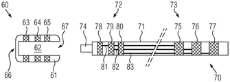
The foregoing aspects and embodiments and advantages of the various aspects of the present invention will be explained hereinafter with reference to fig. 4A and 4B, which schematically illustrate an assembled embodiment of an electrical connector cap 60 and a lead member 70 to form an embodiment of an implantable lead assembly 100 according to another aspect of the present invention. Specifically, fig. 4A illustrates the electrical connector cap 60 proximate to the lead member 70 but unassembled, while fig. 4B illustrates the assembled implantable lead assembly 100 with the electrical connector cap mounted onto the lead member 70.
Here, the electrical connector cap 60 comprises an elongated body 61 having a lumen 62 therein extending between a proximal opening 66 and a distal opening 67, and three electrically conductive members 63, 64, 65 are provided on the elongated body, in particular longitudinally spaced from each other. As noted above, the selection of three conductive members may be particularly advantageous when combined with the IS-4 and DF-4 standards. However, as also noted above, the present invention is applicable to other connection standards or requirements such that embodiments of the electrical connector cap may include more or less than three conductive members without departing from the scope of the present invention.
Although illustrated in a simplified manner, the embodiment shown in fig. 4A and 4B will be used to discuss the above-mentioned aspects and advantages. Thus, it should be understood that the electrical connector cap 60 represented in fig. 4A and 4B may correspond to any embodiment or combination of embodiments described above, or variations thereof, for the sake of understanding. Specifically, the electrical connector hat 60 may be the electrical connector hat 20 or a variation thereof, and the electrically conductive members 63, 64, 65 may be the electrically conductive members 28, 29, 30 or the electrically conductive member 50 as described above or a variation thereof. The skilled reader is therefore referred back to the above disclosure. In particular, while the embodiments discussed hereinafter have particular advantages for more standardizing the components used in the IS-4 and DF-4 connection ranges, those skilled in the art of implantable leads will recognize that the teachings of the present invention are adaptable to other standards.
As can be taken, for example, from fig. 4A and 4B, a guide member 70 that can be used with the electrical connector cap 60 to form an implantable guide assembly 100 according to an aspect of the present invention has an elongated guide body 71 that can be substantially tubular in shape and have a proximal end 72 and a distal end 73. For the purposes of illustration, the guide body 71 is interrupted rather than illustrated in its full length and only the parts towards both ends of the guide body are shown. Furthermore, the guide body 71 comprises at least one lumen, which is not illustrated for the sake of simplicity. Depending on the embodiment, the guide body 71 may have only one primary lumen, or the guide body may be a multilumen guide body 71. The proximal end 72 is configured to be received in the electrical connector cap 60 and, when assembled therewith, to be inserted into a dedicated receptacle of a housing of an active implantable medical device. Further, the distal end 73 is configured for sensing and/or stimulating tissue.
Similar to the implantable lead 1 illustrated in fig. 1, the distal end 73 of the lead member 70 may include a set of distal electrodes, here represented as ring electrodes 75, 76, 77. However, unlike the exemplary version illustrated in fig. 1, each distal electrode 75, 76, 77 of the guide member 70 of the embodiment illustrated in fig. 4A and 4B is connected to a respective proximal contact port, here denoted as annular contact ports 78, 79, 80, which are electrically conductive members that can be similar in most respects to the distal electrodes 75, 76, 77. In particular, the contact ports 78, 79, 80 may be implemented using the same technology as the distal electrodes 75, 76, 77, which may facilitate the overall manufacturing process of the guide member 70. However, it should be understood that the proximal contact port can be implemented in different ways, for example as a junction emerging from the guide body 71 and/or even as a closed or open ring, such as is detailed later in the embodiments described with reference to fig. 5 to 10.
Furthermore, one or more electrically conductive wires, here at least three visible electrically conductive wires 81, 82, 83, are arranged within the guide body 71. Depending on the type of lead body 71, all or only some of the conductive wires, such as conductive wires 81, 82, 83, may be disposed within a single primary lumen, or each conductive wire may be disposed within a respective lumen of a multi-lumen lead body. In any case, also unlike the typical solution, there is no need for any interconnection in the conductive wires implemented by the conductive wires 81, 82, 83, which connect the distal electrodes 75, 76, 77 to the proximal contact ports 78, 79, 80. Those skilled in the art will appreciate such technical advantages over the exemplary approach that can be applied to other numbers of conductive wires, distal electrodes, and proximal contact ports in other embodiments using other criteria than IS-4 or DF-4.
For example, it can be taken from the above disclosure that the electrical connector cap 60 does not include an axial pin in order to be compatible with both the IS-4 and DF-4 standards. Thus, for example, as schematically illustrated in fig. 4A, an axial needle 74 may be mounted at the proximal end 72 of the guide member 70. Thus, it is also possible to dedicate one or more electrically conductive members (here e.g. electrically conductive members 64, 65) of the electrical connector cap 60 to high voltage lines. One or more conductive members (here, for example, conductive member 63) and/or axial pins 74 may also be dedicated to the hypotenuse. In some embodiments, the axial needle 74 is rotatable relative to the guide member 70, in particular relative to the guide body 71. Without limitation, at least in some embodiments in which the implantable lead assembly 100 is a defibrillation lead, the axial pin 74 is rotatable relative to the electrical connector cap 60.
In the assembled state of the implantable lead assembly 100, as shown in fig. 4B, the electrical connector cap 60 is fully mounted over the proximal end 72 of the lead member 70. In other words, the proximal end 72 of the guide member 70 is fully inserted in the electrical connector cap 60, with the proximal end 72 abutting against the proximal opening 76 of the electrical connector cap 60 and the axial pin 74 having been inserted and protruding through said proximal opening 76.
The interconnection between the electrically conductive members 63, 64, 65 of the electrical connector cap 60 and the proximal contact ports 78, 79, 80 of the proximal end 72 of the guide member 70 can then be carried out by known techniques, such as by laser welding. Such operation is facilitated by the presence of through holes in the conductive members 63, 64, 65, as described in the previous embodiments, for example. Depending on the shape of the proximal conductive member provided on the lead body for the electrical connector cap according to the invention (which may be different from the annular contact ports 78, 79, 80), it may be desirable to align the through-holes of the conductive members 63, 64, 65 with the underlying contact ports or proximal conductive members of the lead body. This may be desirable, for example, if these components are implemented as joints exposed from the guide body rather than the annular contact ports 78, 79, 80 of the embodiment illustrated in fig. 4A and 4B. When the conductive members 63, 64, 65 include internal tabs similar to those in the embodiment described with reference to fig. 3, a physical connection may be achieved between the conductive members 63, 64, 65 and the contact ports 78, 79, 80 (particularly when the contact ports are exposed from the guide body 70) so that a high quality interconnection may be achieved, particularly when using laser welding techniques.
Further, after welding and/or gluing, where applicable, one or more protective and/or insulative sleeves (not illustrated) may be added over the distal end of electrical connector cap 60 and at least a portion of lead body 70 exposed from distal opening 67. Advantageously, when the distal end portion of the elongated body 61 of the electrical connector cap 60 comprises one or more additional through holes similar to the additional through holes 42, 43 described in the previous embodiments with reference to fig. 2A and 2B, these additional through holes 42, 43 may be used as mechanical attachment points for the protective and/or insulating sleeve.
When the electrical connector cap 60 IS mounted and fixed to the proximal end 72, in particular by laser welding and/or gluing as described above, a distinction can be made between the IS-4 and DF-4 types, for example by adapting the portion of the axial pin 74 protruding from the proximal opening 66 of the electrical connector cap 60 to an axial pin that can be inserted into a socket of the described connector type. This may be accomplished by welding an IS-4 or DF-4 profiled stylus (not illustrated) to the protruding axial pin 74, thereby implementing an implantable lead assembly 100 whose connector plug IS in accordance with the described standards. In other embodiments, other profiled contact pins may be welded onto axial pins protruding from a proximal opening of an electrical connector cap assembled to the guide member to achieve a connector plug according to any other desired standard.
Those skilled in the art will appreciate that other distinctions may also be made regarding the type level of guide member 70 (single primary lumen, multiple lumens, etc.) and the conductive wires used to implement the conductive wires (or micro-cables where applicable) as well as the particular arrangement of these conductive wires within guide member 70 and the type of proximal contact ports exposed from guide member 70.
Examples of implantable lead members and implantable lead assemblies according to aspects of the present invention will be described later with reference to fig. 5-10. In particular, examples of implantable lead members 200 and corresponding implantable lead assemblies 210 will be described in conjunction with fig. 5-7, and implantable lead members 300 and corresponding implantable lead assemblies 310 will be described in conjunction with fig. 8-10. In particular, the implantable lead members 200, 300 illustrated in fig. 5 to 7 and in fig. 8 to 10, respectively, will serve as examples of how to accommodate lead bodies of the multilumen type or of the type comprising only one main lumen, respectively, for an electrical connector cap according to the above disclosure, to thereby form a corresponding implantable lead assembly also according to the present invention.
Furthermore, in the following embodiments, as explained for example with reference to fig. 4A and 4B, the implantable lead members 200, 300 will be used for an electrical connector cap according to aspects already described above, respectively, to thereby form implantable lead assemblies 210, 310. Thus, in the following embodiments, the electrical connector cap may also be one of the electrical connector caps 20, 60 already described above, or any variant thereof. For details relating to particular aspects of the electrical connector hat according to the invention, the reader refers back to the above description, in particular to the embodiments described with respect to fig. 1 to 3. For further details regarding the implantable lead assembly according to the present invention, the reader also refers back to the above description, particularly to the embodiment described with respect to fig. 4A and 4B.
In any case, similar to the embodiments described above with reference to fig. 5-10, the description of the embodiments will focus on the respective proximal ends of the guide members 200, 300, which are the ends of the guide members that are configured to be connected to the housing of the active implantable medical device. However, a description of the distal end of the guide member 200, 300, which is the end of the guide member configured to sense and/or stimulate tissue, will be omitted as it can be implemented according to well-known techniques as also explained above.
The embodiments illustrated in fig. 5-7 will be used specifically to describe the proximal end of implantable leads of the defibrillation type, such as those constructed in accordance with the DF-4 standard, and to illustrate examples of how the proximal conductive member may be implemented in a multilumen lead body. It should be understood that the particular connection standard is used for purposes of this example only and is not intended to limit the scope of the present invention.
As can be taken for example from the longitudinal section view of fig. 5, an implantable lead member 200 that can be used for an electrical connector cap according to the aforementioned aspect of the invention can comprise an elongated body 201, which is here substantially tubular and of the multilumen type, and has a primary lumen 203 surrounded by a plurality of secondary lumens 202a, 202b, 202c, 202d, 202e, 202f, the last two of which are only visible in the section view of fig. 7. Without being limited thereto, the lead body 201 can therefore be made by extruding or molding a biocompatible (preferably, flexible) material such as polyurethane. It should be understood that the relative arrangement and diameters of the various lumens 202a, 202b, 202c, 202d, 202e, 202f and 203 are not limiting to the present invention, and that other relative arrangements and configurations of multi-lumen bodies may also be suitable to achieve the same function, specifically manufactured for compatible use with electrical connector caps according to aspects of the present invention.
Further, one or more of the secondary lumens 202a, 202b, 202c, 202d, 202e, 202f can receive a respective conductive wire therein to form a conductive wire between the proximal and distal conductive members. For example, as explained above, in the DF-4 standard, three conductive wires may be implemented in three respective lumens out of lumens 202a, 202b, 202c, 202d, 202e, 202f, and one (or more) conductive wire may also be implemented in primary lumen 203. For simplicity, only one conductive wire is represented by the conductive wire 204a in the lumen 202a, but more conductive wires 204b, 204c may be identified in the implantable lead assembly 210 illustrated in fig. 6. As mentioned above, the conductive wire may be implemented as a miniature cable, which is preferred in particular for a guide intended for defibrillation purposes, here for an implantable guide of the DF-4 type.
Furthermore, it can be observed, for example in fig. 5 to 7, that the proximal conductive member of the guide member, similar to the embodiments illustrated in fig. 4A and 4B, of the proximal conductive members 78, 79, 80 of the guide member that can be used in combination with the electrical connector cap can be realized with exposed joints. Here, this is achieved by means of respective tip ends or electrical contacts 206a provided at the proximal end of the conductive wires 204a, which emerge from the inner cavity 202a via respective through holes 205a at the proximal end of the guide body 201. In some embodiments, the electrical contact 206a can be attached to the end of the conductive wire 204a, for example, by soldering and/or crimping and/or gluing and/or any other known method. As more conductive wires may be provided, as many electrical contacts may be provided as exposed junctions towards the proximal end of any other lumen that receives the conductive wires therein. In other words, the configuration illustrated as having the wires 204a, the through-holes 205a, and the contacts 206a may be replicated for any other lumen 202b, 202c, 202d, 202e, 202f (or alternatively even the lumen 203) having conductive wires received therein, similar to the wires 204a in the lumen 202a, and thus also applies here to the wires 204b, 204 c. In embodiments herein, when the guide member 200 is used in a DF-4 standard type defibrillation guide, three exposed junctions in the form of and including exposed electrical contacts similar to the contact 206a may be disposed in three lumens (including lumen 202a), and each lumen is for contacting a respective conductive member of an electrical connector cap according to the present invention. For ease of operation, when several exposed joints are provided, the joints may be spaced in the circumferential and/or longitudinal direction of the guide body 201. Preferably, the longitudinal separation between successive exposed bonds may correspond to the separation between successive electrically conductive members 28, 29, 30 or 78, 79, 80 of an electrical connector hat 20 or 60 according to the invention.
Thus, unlike the known implantable leads discussed above, an implantable lead member 200 may be provided in which a conductive wire may be formed between the distal electrode and the proximal end of the lead body without implementing any interconnection (within the meaning discussed above). This is possible because the exposed electrical contacts substantially correspond to the terminal ends of the respective conductive wires, such as described with respect to the guide member 200, with the electrical contact 206a substantially corresponding to the terminal end for the conductive wire 204 a.
Fig. 6 illustrates a longitudinal cross-sectional view of an implantable lead assembly 210 according to aspects of the present invention formed from the implantable lead member 200 illustrated in fig. 5, and to which the electrical connector cap 20 (or 60) of the embodiment illustrated in fig. 2A and 2B (or 4A and 4B) is mounted. Fig. 7 illustrates a cross-sectional view of the implantable lead assembly 210. Thus, the electrical connector cap according to the present invention is mounted on the proximal end of the guide member 200 illustrated in fig. 5. This forms an implantable lead assembly 210 similar to the lead assembly 100 described in the embodiment with reference to fig. 4A and 4B. For simplicity, the electrical connector hat 20 illustrated in fig. 6 and 7 is the same as the electrical connector hat in fig. 2A and 2B. It should be understood that the electrical connector cap may also be the electrical connector cap 60 of the embodiment illustrated in fig. 4A and 4B or any of the variations described above. The reader is therefore also referred to the above disclosure.
Optionally, the stylus assembly 211 may have been installed in the primary lumen 203 of the guide body 201 prior to installing the electrical connector cap 20 on the proximal end of the guide member 200. As can be taken from fig. 6, for example, the stylus assembly 211 may include an axial stylus 212 partially received in the main lumen 203 of the guide body 201 and partially protruding from the proximal end of the guide body 201. If so desired, the portion of the axial stylus 212 received in the primary lumen 203 may be covered by an optional insulating sleeve 217, visible at least in fig. 7 and preferably made of a biocompatible material, and the stylus assembly 211 may further include additional components along the axial stylus 212 such as one or more optional stop rings 213 and one or more optional sealing rings 214. In some embodiments, an optional internal coil with a fastening mechanism such as a screw (not illustrated) may be disposed within the implantable lead assembly 210, particularly through the primary lumen 203 and/or an axial stylus 212, which may then preferably be tubular. Preferably, the axial stylus 212 may be arranged to be rotatable relative to the guide body 201. Furthermore, the axial stylus 212 may also be connected to the distal sensing and/or stimulation electrodes via electrically conductive wires. Further, the portions of the axial contacts 212 of the contact pin assembly 211 that protrude through the proximal end of the body 21 of the electrical connector cap 20 can be configured according to a particular connection standard. To this end, as shown in fig. 6, a tip end 215 configured (specifically shaped) for a particular standard desired can be provided over the protruding portion of the axial stylus 212. To this end, the terminal end 215 may be attached, for example, using known welding, laser welding, or other known methods. In the illustrated embodiment, the terminal end 215 may be configured, specifically shaped, to correspond to the DF-4 standard. While this example is intended to illustrate a particular type of standard connector, it should be understood that other embodiments may involve different types of standard connectors without departing from the scope of the present invention.
Furthermore, as shown in fig. 6 and 7, when the electrical connector cap 20 is mounted over the proximal end portion of the lead member 200, the portions of the conductive members 28, 29, 30 extending in the respective through holes 24, 25, 26 of the electrical connector cap 20 may be arranged to face the respective exposed electrical contacts of the respective conductive wires of the lead member 200, as the conductive members 28, 29, 30 of the lead member extend into the internal cavity 22 via the respective through holes 24, 25, 26 of the elongated body 21 of the electrical connector cap 20. In the embodiment illustrated in fig. 6 and 7, the conductive members 28, 29, 30 are implemented as annular conductive members 50 similar to the embodiment illustrated in fig. 3. When the electrical connector cap 20 is mounted on the proximal end of the lead member 200, the respective internal tabs of the conductive members 28, 29, 30 may thereby establish physical contact with the underlying respective electrical contacts exposed from the lead member 200. Here, as shown in fig. 6 and particularly in fig. 7, the inner protrusion of the conductive member 28 faces and contacts the electrical contact 206 a. The through-hole 31 of the conductive member 28 may facilitate visual control of the position of the exposed electrical contact 206a below with respect to the conductive member 28, thereby controlling the mounting position of the electrical connector cap 20 on the proximal end of the lead body 201. It may also be convenient to fixedly secure conductive member 28 to exposed electrical contact 206a using techniques such as laser welding. Of course, such operation may be repeated as desired for the plurality of conductive members 28, 29, 30 and the corresponding exposed electrical contacts thereunder to fixedly secure the electrical connector cap 20 to the lead member 210. Optionally, the electrical connector cap 20 may further be attached to the lead member 200, in particular to the lead body 201 and insulated, for example by injecting an adhesive through one or more through holes provided in the lead body 201 and/or between the lead body 201 and the elongated body 21 of the electrical connector cap 20 to fill any space or volume between the lead body and the elongated body.
In the embodiments illustrated in fig. 5 to 7, an implantable lead assembly 210 may thus be realized which may be used in particular for defibrillation when combined with a housing comprising a DF-4 type socket. In this case, the wires using the conductive members 29, 30 may be high voltage wires, and the wires using the conductive member 28 and the stylus assembly 211 may be low voltage wires. However, the particular connection standards and assignments of the low and/or high voltage lines do not limit the scope of the invention.
Further, as shown in fig. 6, the implantable lead assembly 210 may include one or more protective and/or reinforcing and/or insulating sleeves similar to sleeve 216 that can be slid over the lead body 201 and preferably also over the rear or distal portion of the electrical connector cap 20 and attached thereto, particularly using adhesives and/or mechanical means. For example, the sleeve 216 may be clamped to a rear or distal portion of the electrical connector cap 20 using additional through holes 42, 43. In this way, the portion of the lead body 201 exposed from the electrical connector cap 20 may be reinforced, protected, and/or insulated. For example, body fluids may be prevented from penetrating, in particular filtering, into the distal portion of the electrical connector cap 20, thereby enhancing prevention of electrical shortages. Optional sleeve 216 may be made of silicon or any other suitable flexible biocompatible material.
In the following, the embodiments illustrated in fig. 8 to 10 will be used in particular for describing the proximal end of implantable leads of the stimulation or pacing type, for example an implantable lead constructed according to the IS-4 standard, and for illustrating an example of how the proximal conductive member IS implemented in a lead body comprising only one lumen. Furthermore, it should be understood that the particular connection standard is used only to illustrate the application of the present invention, and should not be taken as limiting the scope of the invention.
As can be taken from fig. 8, for example, in a further embodiment, the implantable lead member 300, which may be used for the electrical connector cap according to the aforementioned aspect of the invention, may still comprise an elongated body 301, which is here also substantially tubular. However, unlike the embodiment described with reference to fig. 5 to 7, the guide body 301 has only one lumen 302. Preferably, the lumen 302 may be centered about the major axis of the guide body 301, although this aspect should not be considered as limiting the scope of the invention. Thus, a guide body comprising an eccentrically disposed primary lumen or comprising more than one lumen may also be used. Again without limiting the scope of the invention herein, the lead body 301 may be made by extruding or molding a biocompatible (preferably, flexible) material such as polyurethane.
In IS-4 type leads, up to four conductive wires are typically required, and typically all conductive wires are dedicated to low voltages. Thus, as shown in fig. 8, four conductive wires 304a, 304b, 304c, 304d may be disposed within the internal cavity 302. In a preferred construction (not visible), the electrically conductive wires 304a, 304b, 304c, 304d are disposed within the internal cavity 302 in a helical manner such that a central portion of the internal cavity 302 is left empty, e.g., for subsequent insertion of an optional pin contact assembly. However, in other embodiments, the conductive wires 304a, 304b, 304c, 304d may be arranged in a simple linear configuration within the internal cavity 302. However, the latter configuration is not as advantageous as a helical configuration, which provides better resistance to mechanical stress in both flexural and tensile forces. Similar to the embodiments described above, the number of conductive wires and the configuration of the wires should not be construed as limiting the invention. Thus, in other embodiments, more or fewer conductive wires and associated wires may be used.
In contrast to the embodiments described with reference to fig. 5 to 7, fig. 8 also shows another way of implementing the proximal electrically conductive member of the guide member that can be used in combination with the electrical connector cap according to the present invention. As mentioned above with respect to the proximal conductive members 78, 79, 80 of the embodiment illustrated in fig. 4A and 4B, for example, the proximal conductive members can be implemented as exposed bonds and/or annular members. The latter configuration will be described later.
As shown for example in particular in fig. 8, at least some of the electrically conductive wires 304a, 304b, 304c, 304d may be connected to ring-shaped proximal electrically conductive members 307a, 307b, 307c, 307d arranged on, in particular clamped on and/or sliding on, an outer circumference of the guide body 301 towards the proximal end thereof. In view of the use of guide member 300 in combination with an electrical connector hat according to other aspects of the present invention, at least some of the annular proximal electrically conductive members 307a, 307b, 307c, 307d may be spaced from each other in a similar manner as the spacing between the electrically conductive members of the electrical connector hat. For example, as shown particularly in fig. 9, at least three annular proximal conductive members 307a, 307B, 307c may be spaced apart according to conductive members 28, 29, 30 of electrical connector cap 20 of the embodiment illustrated in fig. 2A and 2B.
As also shown in fig. 8, the annular proximal conductive members 307a, 307b, 307c, 307d need not be closed rings and may be provided as open rings. Preferably, the circumference of the annular proximal conductive members 307a, 307b, 307c, 307d may extend at least about 180 ° or even more. The rounded ends and at least 180 ° may facilitate subsequent installation of an electrical connector cap, such as electrical connector cap 20, to form an implantable lead assembly similar to lead assembly 310 illustrated in fig. 9 and 10. Furthermore, the outer diameter of the ring-shaped proximal conductive members 307a, 307b, 307c, 307d may correspond to the diameter of the lumen in the electrical connector cap according to the invention. In the illustrated embodiment, as shown in fig. 9 and 10, the outer diameter of annular proximal conductive members 307a, 307b, 307c, 307d may correspond to the diameter of lumen 22 within electrical connector cap 20. Further, as can be taken from fig. 8, for example, to better secure these annular proximal conductive members to the guide body 301, the inner diameters of the annular proximal conductive members 307a, 307b, 307c, 307d can substantially correspond to the outer diameter of the guide body 301. Furthermore, the open annular proximal conductive members 307a, 307b, 307c, 307d may be pressed as desired for better attachment, in particular clamping, on the lead body 301.
The electrical connection between the conductive wires 304a, 304b, 304c, 304d and the looped proximal conductive members 307a, 307b, 307c, 307d can be accomplished in a variety of ways. In the embodiment specifically illustrated in fig. 8, the electrically conductive wires 304a, 304b, 304c, 304d may exit the lumen 302 via the respective through- holes 305a, 305b, 305c, 305d such that the respective uninsulated end portion 306a, 306b, 306c of each wire 304a, 304b, 304c, 304d is exposed outside of the guide body 301. In a manner somewhat similar to the embodiment with reference to fig. 5-7, the exposed end portions 306a, 306b, 306c of each wire 304a, 304b, 304c, 304d may in principle form an exposed type of electrical joint. Thus, in principle, these end portions may independently serve as proximal conductive members. However, the exposed end portions 306a, 306b, 306c may be less reliable than the exposed bonds implemented by the electrical contacts 206a in the embodiment illustrated in fig. 5-7. Thus, in this configuration, the use of annular proximal conductive members 307a, 307b, 307c, 307d is preferred.
Alternatively, instead of the respective through holes 305a, 305b, 305c, 305d, slots may be provided along the proximal end of the guide body 301, such that the exposed end portions 306a, 306b, 306c, 306d will protrude from the guide body 301 via the slots. In such an alternative configuration, such slots may then be closed or glued together, even roughly closed or glued together, for example using a polymeric adhesive, after the exposed end portions 306a, 306b, 306c, 306d are provided.
Further, at least the through holes 305a, 305b, 305c may preferably be spaced according to the conductive member of the electrical connector cap according to the present invention. Here, like the ring-shaped conductive members 307a, 307B, 307c, at least the through holes 305a, 305B, 305c and thereby at least the exposed end portions 306a, 306B, 306c may also be spaced apart according to the conductive members 28, 29, 30 of the electrical connector cap 20 of the embodiment illustrated in fig. 2A and 2B.
In any case, when the looped proximal conductive members 307a, 307b, 307c, 307d are mounted on the lead body 301, the exposed end portions 306a, 306b, 306c, 306d of the conductive wires 304a, 304b, 304c, 304d can be brought into contact with a respective one of the looped proximal conductive members 307a, 307b, 307c, 307 d. The exposed end portions 306a, 306b, 306c, 306d may then be fixedly secured to the looped proximal conductive members 307a, 307b, 307c, 307d, such as by laser welding or any other equivalent technique. To protect the underlying lead body 301 from damage during such procedures, the annular proximal conductive members 307a, 307b, 307c, 307d may be provided with optional grooves or recesses for receiving the exposed end portions 306a, 306b, 306c, 306d of the conductive wires 304a, 304b, 304c, 304 d. Here, fig. 8 shows that each annular proximal conductive member 307a, 307b, 307c, 307d is provided with a respective recess 308a, 308b, 308c, 308d to receive a respective exposed end portion 306a, 306b, 306c, 306 d. As described above, laser welding or equivalent techniques may be used to fixedly secure end portions 306a, 306b, 306c, 306d to members 307a, 307b, 307c, 307d, and in particular to grooves 308a, 308b, 308c, 308 d.
However, the connection between the exposed end portions 306a, 306b, 306c, 306d and the annular proximal conductive members 307a, 307b, 307c, 307d need not be limited to the embodiment illustrated in fig. 8-10. In other embodiments, the proximal conductive member of the guide member of the present invention may be implemented in a manner similar to conductive members 28, 29, 30, or 50 described above. Accordingly, the annular proximal conductive members 307a, 307b, 307c, 307d may be provided with internal protrusions in the through holes 305a, 305b, 305c, 305d to establish electrical connection when the end portions 306a, 306b, 306c, 306d of the conductive wires 304a, 304b, 304c, 304d are not exposed from the lumen 302.
In other words, the present invention allows for the proximal conductive member of the guide member to be provided as an exposed joint, a ring-shaped member, or a combination of both. For example, it has been mentioned with reference to the previous embodiments that the number of proximal conductive members in the guide member according to the invention is not limited to the configuration of the illustrated embodiment and should be adapted to the number of conductive wires required for a certain application (guide with standard or non-standard connector member, cardiac/lung/nervous system/brain application, etc.).
Next, fig. 9 illustrates a partial longitudinal cross-sectional view of an implantable lead assembly 310 formed from the implantable lead member 300 illustrated in fig. 8, and upon which an electrical connector cap according to other aspects of the present invention has been mounted. Here, the electrical connector cap 20 (or 60) of the embodiment illustrated in fig. 2A and 2B (or 4A and 4B) is shown for simplicity. Further, fig. 10 illustrates a cross-sectional view of the implantable lead assembly 310. The lead assembly 310 IS substantially similar to the lead assemblies 100, 210 of the previous embodiments, except that this example IS intended to illustrate an IS-4 type pacing/stimulation lead. The reader is therefore also referred to the above disclosure for further details.
Optionally, the stylus assembly 311 may have been installed in the primary lumen 302 of the guide body 301 prior to installing the electrical connector cap 20 on the proximal end of the guide member 300. As can be taken from fig. 9, for example, the stylus assembly 311 may comprise an axial stylus 312 partially received in the main lumen 302 of the guide body 301 and partially protruding from the proximal end of the guide body 301. Thus, the axial contact pins 312 may also protrude from the proximal end of the mounted electrical connector cap 20 in the guide assembly 310.
If so desired, the stylus assembly 311 may include additional components such as one or more optional stops and/or sealing rings (here, for example, a ring 314 abutting against the free end of the guide body 301) and may be provided integrally with the axial stylus 312. Since the illustrated embodiment shows the guide assembly 310 using the IS-4 standard, an axial stylus 312 IS connected to one of the respective conductive wires. In this regard, due to the selected criteria and the corresponding necessary predetermined spacing between conductive members 28, 29, 30 of electrical connector hat 20, it is necessary to define corresponding spacing between corresponding annular proximal conductive members 307a, 307b, 307c, 307 d. Thus, the three most proximal annular proximal conductive members 307a, 307b, 307c may be provided, in particular arranged, to meet the standard spacing of conductive members 28, 29, 30 of electrical connector cap 20. Thus, the fourth ring-shaped proximal conductive member 307d attached to the fourth wire 304d is freely connected to the axial contact pin 312, e.g., to the ring 314. As shown in fig. 9, in these embodiments, such connection is achieved by means of an electrically conductive wire 316 connected at one end to the axial contact pin 312 and at the other end 317 to a fourth annular proximal electrically conductive member 307 d. The latter connection can be achieved in a manner similar to that described above with respect to the exposed end portions 306a, 306b, 306c, 306d of the conductive wires 304a, 304b, 304c, 304 d.
In alternative embodiments, the connection of the electrical wires to the axial contact pins 312 can be provided in different ways. For example, a fourth annular proximal conductive member 307d and additional conductive wire 316 may be avoided, whereby the exposed end portion 306d may not need to be exposed from the guide body 301 and may be directly connected to the axial contact pin 312, while the conductive wire 304d is provided with the necessary length. However, in the illustrated embodiment, the fourth low voltage electrical wire is provided in a similar manner to the other three wires, i.e. using corresponding annular conductive members 307a, 307b, 307c, 307d, to standardize and/or simplify the manufacturing and/or assembly process.
Since the embodiment illustrated in fig. 9 and 10 represents the use of the IS-4 standard guide assembly 310 in a manner similar to that described above for the previous embodiments, the portion of the axial stylus 312 of the stylus assembly 311 that protrudes through the proximal end of the body 21 of the electrical connector cap 20 can be configured according to the desired connection standard. To this end, as shown in particular in fig. 9, a tip end 315 configured, in particular shaped, for the particular standard desired (here the IS-4 standard) can be provided over a protruding portion of the axial stylus 312. Similar to the previous embodiments, it should be understood that such optional tip end 315 may be attached using known techniques, specifically welding, laser welding, and the like. Again, the particular configuration of the optional tip end 315 should not be considered a limiting factor to the present invention.
As shown in fig. 9 and 10, when the electrical connector cap 20 is mounted over the proximal end portion of the lead member 300, the portions of the electrically conductive members 28, 29, 30 extending in the respective through holes 24, 25, 26 of the electrical connector cap 20 may be arranged to face the respective one of the most proximal annular electrically conductive members 307a, 307b, 307c, as the electrically conductive members 28, 29, 30 of the lead member extend into the lumen 22 via the respective through holes 24, 25, 26 of the elongate body 21 of the electrical connector cap 20. In the embodiment illustrated in fig. 9 and 10, the conductive members 28, 29, 30 are implemented as a preferred variation of the annular conductive member 50 similar to the embodiment illustrated in fig. 3. Thus, when the electrical connector cap 20 is mounted on the proximal end of the guide member 300, the respective internal protrusions of the electrically conductive members 28, 29, 30 may thereby establish physical contact uniformly with the underlying respective electrical contacts or contact ports of the guide member 300. As can be taken, for example, from fig. 10, in these embodiments the inner protrusion of each conductive member 28, 29, 30 faces and is in contact with a region of the outer surface of a corresponding one of the three most proximal annular conductive members 307a, 307b, 307 c. While the view of fig. 10 details the contact between conductive member 28 and proximal annular conductive member 307a, those skilled in the art will appreciate that a similar configuration can be achieved between conductive member 28 and proximal annular conductive member 307b and between conductive member 30 and proximal annular conductive member 307 c.
Further, it is also mentioned with reference to some of the foregoing embodiments that the through- holes 31, 32, 33 extending through the inner protrusions may facilitate visual control of the position of the underlying contact ports, here the three most proximal annular conductive members 307a, 307b, 307c, relative to the conductive members 28, 29, 30. Thus, the mounting position of the electrical connector cap 20 on the proximal end of the lead body 301 can be controlled. Vias 31, 32, 33 may also facilitate the use of techniques such as laser welding to fixedly secure one or more, and preferably all, conductive members 28, 29, 30 to corresponding lower annular conductive members 307a, 307b, 307 c.
Furthermore, as described above, the electrical connector cap 20 may optionally be further attached to the lead member 300, in particular to the lead body 301, for example by injecting an adhesive into the space between the lead body 301 and the electrical connector cap 20. This is also advantageous because it provides additional insulation between the four wires.
Thus, an implantable lead assembly 310 may be implemented that may be particularly useful for cardiac stimulation and/or pacing when combined with a dedicated housing that includes a corresponding IS-4 type receptacle. However, as noted above, it should be understood that the particular connecting surface does not limit the scope of the present invention. Rather, the present invention is intended to illustrate the flexibility of the present invention with which various configurations of implantable leads may be provided. The invention IS particularly advantageous in the particular case of IS-4 and DF-4 connections, as it allows the use of the same electrical connector cap.
In any case, as shown in fig. 9, in some embodiments, the implantable lead assembly 310 can include one or more protective and/or reinforcing and/or insulating sleeves similar to sleeve 318 that can be slid over the lead body 301 and preferably also over the rear or distal portion of the electrical connector cap 20 and attached thereto, for example using adhesives and/or mechanical means. Further, here, optional sleeve 318 may be used to prevent body fluids from penetrating, in particular filtering, into the distal portion of electrical connector cap 20, thereby enhancing prevention of electrical shortages. To this end, optional sleeve 216 may be made of silicon or any other suitable flexible biocompatible material.
Thus, with the present invention, implantable lead assemblies, such as lead assemblies 100, 210, 310, can be achieved in which any interconnection forming wires between the distal and proximal ends of the lead members moves inside the electrical connector cap. To do so, unlike known implantable leads, the present invention allows to completely avoid the creation of weakened areas at the level of the lead body emerging from the rear or distal end of the connector member. Indeed, with the present invention, any interconnection is now implemented inside the electrical connector cap between the electrically conductive member (or contact port) of the electrical connector cap and the proximal electrically conductive member (or contact port) of the proximal end portion of the guide member.
In particular, the invention has the advantage that standardized electrical connector caps with high added value can be produced in a single production line, while being compatible with more than one connection standard. For example, the present invention provides a single standardized electrical connector that IS compatible with both the IS-4 and DF-4 standards without modification.
Furthermore, an advantage of the present invention is that the construction of the implantable lead or lead assembly can be made more reliable than typical applications, since no electrical interconnections are required within the lead member, especially in the region immediately behind the distal opening of the electrical connector cap, which is a region known to be subjected to strong mechanical stresses. Indeed, with the present invention, the interconnection is implemented in a reliable manner between the proximal end of the lead member and the electrical connector cap, in a protected environment, directly between each conductive member of the electrical connector cap and the corresponding proximal conductive member of the lead member.
Furthermore, in addition to improved mechanical stability, embodiments of the present invention allow avoiding electrical shortages between electrically conductive wires, in particular between two high voltage wires.
Claims (25)
1. An implantable lead assembly (100, 210, 310) comprising:
an elongated guide body (71) having a proximal end (72) and a distal end (73) and at least one lumen, the proximal end being the end of the guide body (71) for connection to a housing of an active implantable medical device and the distal end being the opposite end of the guide body (71) configured for sensing and/or stimulating tissue; and
at least one electrically conductive wire (81, 82, 83) disposed in the at least one lumen;
the at least one electrically conductive wire (81, 82, 83) being in electrical contact at the distal and proximal ends (73, 72) with respective distal or proximal electrically conductive members (75, 76, 77, 78, 79, 80) provided on an outer periphery of the guide body (71);
it is characterized in that the preparation method is characterized in that,
the implantable lead assembly (100, 210, 310) further comprises an electrical connector cap (60) mounted over the proximal end (72), the electrical connector cap being arranged such that a proximal conductive member (78, 79, 80) at least partially contacts a respective conductive member (63, 64, 65) of the electrical connector cap (60);
the electrical connector cap (60) comprising an elongate body (21) having at least one lumen (22) and at least one through hole (24, 25, 26) extending from an outer surface (27) of the elongate body (21) into the lumen (22); and
at least one electrically conductive member (28, 29, 30, 50) disposed on an outer periphery of the elongated body (21) over at least one through hole (24, 25, 26) of the elongated body (21);
wherein the at least one electrically conductive member (28, 29, 30, 50) comprises at least one through hole (31, 32, 33, 54) extending from an outer surface of the electrically conductive member (28, 29, 30, 50) into the lumen (22) through the at least one through hole (24, 25, 26) of the elongated body (21);
wherein the elongated body (21) is a one-piece component made of a biocompatible insulating material.
2. The implantable lead assembly (100, 210, 310) according to claim 1, wherein when the elongated body (21) has more than one through hole (24, 25, 26), the one or more through holes (24, 25, 26) are longitudinally offset along the elongated body (21) and/or offset relative to each other in a circumferential direction of the elongated body (21).
3. The implantable lead assembly (100, 210, 310) of claim 1, wherein the diameter of the lumen (22) is constant over a major central portion of the elongate body (21) and decreases at a proximal portion of the elongate body (21).
4. The implantable lead assembly (100, 210, 310) according to claim 3, wherein the diameter of the lumen (22) decreases stepwise at the proximal portion.
5. The implantable lead assembly (100, 210, 310) according to claim 1 or 2, wherein the diameter of the lumen (22) is larger at a distal portion of the elongate body (21) than at a predominantly central portion of the elongate body (21).
6. The implantable lead assembly (100, 210, 310) according to claim 1, wherein the distal end portion of the elongated body (21) includes at least one additional through hole (42, 43).
7. The implantable lead assembly (100, 210, 310) according to claim 6, wherein the at least one additional through-hole (42, 43) is devoid of any conductive member.
8. The implantable lead assembly (100, 210, 310) according to claim 1, wherein an outer diameter of the elongate body (21) decreases at a distal portion of the elongate body.
9. The implantable lead assembly (100, 210, 310) according to claim 8, wherein the outer diameter of the elongate body (21) decreases in a stepwise manner at the distal end portion of the elongate body.
10. The implantable lead assembly (100, 210, 310) according to claim 1, wherein the elongated body (21) includes at least one recessed area (37, 38, 39) along the outer periphery, the at least one through hole (24, 25, 26) of the elongated body (21) is in the corresponding recessed area (37, 38, 39), and the at least one conductive member (28, 29, 30, 50) is disposed in the respective recessed area (37, 38, 39).
11. The implantable lead assembly (100, 210, 310) according to claim 10, wherein the at least one recessed area (37, 38, 39) extends along an entire outer circumference of the elongated body (21).
12. The implantable lead assembly (100, 210, 310) of claim 11, wherein the at least one recessed area is annular.
13. The implantable lead assembly (100, 210, 310) according to claim 1 or 2, wherein an outer surface (34, 35, 36, 51) of the at least one conductive member (28, 29, 30, 50) is flush with an outer surface of the elongate body (21).
14. The implantable lead assembly (100, 210, 310) according to claim 1, wherein the at least one conductive member (28, 29, 30, 50) has an internal protrusion (53) extending in a respective through hole (24, 25, 26) of the elongate body (21).
15. The implantable lead assembly (100, 210, 310) according to claim 14, wherein the internal tabs extend radially inward in the respective through holes (24, 25, 26) of the elongated body (21).
16. The implantable lead assembly (100, 210, 310) of claim 14, wherein the internal protrusion (53) is flush with the inner surface (23) or lumen (22) of the elongate body (21).
17. The implantable lead assembly (100, 210, 310) according to claim 14 or 16, wherein the at least one through hole (31, 32, 33, 54) of the at least one conductive member (28, 29, 30, 50) extends through the internal protrusion (53).
18. The implantable lead assembly (100, 210, 310) according to claim 14 or 16, wherein the at least one through hole (31, 32, 33, 54) of the at least one conductive member (28, 29, 30, 50) extends radially through the internal protrusion (53).
19. The implantable lead assembly (100, 210, 310) according to claim 1, wherein at least one proximal conductive member (63, 64, 65) is an exposed electrical junction and/or an at least partially annular member.
20. The implantable lead assembly (100, 210, 310) according to claim 1, wherein the at least one proximal conductive member (307a-307d) is at least partially annular.
21. The implantable lead assembly (100, 210, 310) according to claim 20, wherein the at least one proximal conductive member (307a-307d) is an open loop-shaped member.
22. The implantable lead assembly (100, 210, 310) of claim 21, wherein the at least one proximal conductive member (307a-307d) is an open loop-shaped member having a circumference extending over more than 180 °.
23. The implantable lead assembly (100, 210, 310) according to claim 20 or 21, wherein an inner diameter of the at least one proximal conductive member (307a-307d) corresponds to an outer diameter of the elongate lead body (301).
24. The implantable lead assembly (100, 210, 310) according to claim 20 or 21, wherein the at least one proximal conductive member (307a-307d) includes a groove or recess (308a-308 d).
25. The implantable lead assembly (100, 210, 310) according to claim 1 or 2, wherein an outer diameter of the at least one proximal conductive member (307a-307d) corresponds to an inner diameter of the lumen (22, 62) of the electrical connector cap (20, 60), whereby the at least one proximal conductive member (307a-307d) at least partially contacts the respective conductive member (28, 29, 30, 63, 64, 65) of the electrical connector cap (20, 60).
Applications Claiming Priority (2)
| Application Number | Priority Date | Filing Date | Title |
|---|---|---|---|
| EP17306231.6A EP3459593B1 (en) | 2017-09-20 | 2017-09-20 | Implantable lead assembly comprising an electrical connector cap for an implantable lead and said lead |
| EP17306231.6 | 2017-09-20 |
Publications (2)
| Publication Number | Publication Date |
|---|---|
| CN109524863A CN109524863A (en) | 2019-03-26 |
| CN109524863B true CN109524863B (en) | 2020-10-02 |
Family
ID=60001821
Family Applications (1)
| Application Number | Title | Priority Date | Filing Date |
|---|---|---|---|
| CN201811087335.6A Active CN109524863B (en) | 2017-09-20 | 2018-09-18 | Implantable lead assembly |
Country Status (3)
| Country | Link |
|---|---|
| US (1) | US11219773B2 (en) |
| EP (1) | EP3459593B1 (en) |
| CN (1) | CN109524863B (en) |
Families Citing this family (4)
| Publication number | Priority date | Publication date | Assignee | Title |
|---|---|---|---|---|
| CN112618949A (en) | 2019-10-08 | 2021-04-09 | 苏州景昱医疗器械有限公司 | Connector assembly for implantable medical device and method of making same |
| CA3201811A1 (en) * | 2020-11-19 | 2022-05-27 | Phagenesis Limited | Devices, systems, and methods for treating disease using electrical stimulation |
| US20240066292A1 (en) * | 2022-08-28 | 2024-02-29 | Terry Daglow | Neurological Stimulation and Signal Recording Apparatus |
| CN118416397B (en) * | 2024-07-03 | 2024-10-25 | 苏州新云医疗设备有限公司 | Connection module, implantable neural stimulator and transfer connection module |
Family Cites Families (13)
| Publication number | Priority date | Publication date | Assignee | Title |
|---|---|---|---|---|
| US6038472A (en) * | 1997-04-29 | 2000-03-14 | Medtronic, Inc. | Implantable defibrillator and lead system |
| US7146222B2 (en) * | 2002-04-15 | 2006-12-05 | Neurospace, Inc. | Reinforced sensing and stimulation leads and use in detection systems |
| US7062329B2 (en) * | 2002-10-04 | 2006-06-13 | Cameron Health, Inc. | Implantable cardiac system with a selectable active housing |
| FR2875644B1 (en) | 2004-09-20 | 2006-12-15 | Ela Medical Sa | MODULAR ELECTRICAL CONNECTION SHEET, IN PARTICULAR FOR MONOCORPH DEFIBRILLATION PROBE |
| US8000808B2 (en) * | 2005-01-31 | 2011-08-16 | Medtronic, Inc. | Medical lead with segmented electrode |
| US8600518B2 (en) * | 2008-04-30 | 2013-12-03 | Boston Scientific Neuromodulation Corporation | Electrodes for stimulation leads and methods of manufacture and use |
| US8918187B2 (en) * | 2010-03-31 | 2014-12-23 | Medtronic, Inc | Medical leads and related systems that include coiled filars with longitudinally straight ends |
| US20120089203A1 (en) * | 2010-10-12 | 2012-04-12 | Advanced Neuromodulation Systems, Inc. | Electrical connections for use in implantable medical devices |
| EP2559453B1 (en) | 2011-08-18 | 2014-07-16 | Sorin CRM SAS | Lead implantable in the coronary vessels for multi-zone stimulation of a left heart chamber |
| EP2647406B1 (en) * | 2012-04-04 | 2014-10-29 | Sorin CRM SAS | Electrical connection plug for multipolar probe of an active implantable medical device |
| EP2664354B1 (en) | 2012-05-16 | 2015-09-16 | Sorin CRM SAS | Medical lead with a ring electrode for implantation in a cardiac or cerebral blood vessel and a method for its manufacture |
| WO2014101200A1 (en) * | 2012-12-31 | 2014-07-03 | Shanghai Microport Medical (Group) Co., Ltd. | Active cardiac electrical lead |
| WO2015134612A1 (en) * | 2014-03-05 | 2015-09-11 | Medtronic, Inc. | Implantable medical electrical lead connector assemblies and methods of manufacture |
-
2017
- 2017-09-20 EP EP17306231.6A patent/EP3459593B1/en active Active
-
2018
- 2018-09-18 CN CN201811087335.6A patent/CN109524863B/en active Active
- 2018-09-19 US US16/135,949 patent/US11219773B2/en active Active
Also Published As
| Publication number | Publication date |
|---|---|
| US20190083795A1 (en) | 2019-03-21 |
| EP3459593B1 (en) | 2020-10-21 |
| CN109524863A (en) | 2019-03-26 |
| EP3459593A1 (en) | 2019-03-27 |
| US11219773B2 (en) | 2022-01-11 |
Similar Documents
| Publication | Publication Date | Title |
|---|---|---|
| US7241180B1 (en) | Medical electrical lead connector assembly | |
| US6643550B2 (en) | Multi-polar connector | |
| US5514172A (en) | Multi-conductor lead including a connector with an interlocking insulator | |
| US6755694B2 (en) | Lead upsizing sleeve | |
| US7083474B1 (en) | System for lead retention and sealing of an implantable medical device | |
| US8588939B2 (en) | Method of assembling an implantable medical lead having passive lock mechanical body terminations | |
| CN109524863B (en) | Implantable lead assembly | |
| US10084278B2 (en) | Implantable lead assembly | |
| US9227049B2 (en) | Method of manufacturing electrical connection plug for a multipolar lead of an active implantable medical device | |
| US9106004B2 (en) | Implantable medical electrical leads and connector assemblies thereof | |
| US6705900B2 (en) | Lead up-sizing sleeve | |
| US8911265B2 (en) | Electrical connection plug for multipolar lead of active implantable medical device | |
| US12496453B2 (en) | Implantable lead | |
| CN104136069B (en) | Implantable medical lead | |
| CN113457016B (en) | Electrode wires and medical equipment | |
| HK40008039B (en) | Implantable lead assembly comprising an electrical connector cap for an implantable lead and said lead | |
| HK40008039A (en) | Implantable lead assembly comprising an electrical connector cap for an implantable lead and said lead | |
| EP1370325A1 (en) | Lead up-sizing sleeve | |
| HK40006503A (en) | Implantable lead |
Legal Events
| Date | Code | Title | Description |
|---|---|---|---|
| PB01 | Publication | ||
| PB01 | Publication | ||
| SE01 | Entry into force of request for substantive examination | ||
| SE01 | Entry into force of request for substantive examination | ||
| GR01 | Patent grant | ||
| GR01 | Patent grant |