CN109510504B - A hybrid energy storage pulse power supply based on single-phase bridge capacitor conversion - Google Patents
A hybrid energy storage pulse power supply based on single-phase bridge capacitor conversion Download PDFInfo
- Publication number
- CN109510504B CN109510504B CN201811571656.3A CN201811571656A CN109510504B CN 109510504 B CN109510504 B CN 109510504B CN 201811571656 A CN201811571656 A CN 201811571656A CN 109510504 B CN109510504 B CN 109510504B
- Authority
- CN
- China
- Prior art keywords
- thyristor
- power supply
- energy storage
- bridge
- capacitor
- Prior art date
- Legal status (The legal status is an assumption and is not a legal conclusion. Google has not performed a legal analysis and makes no representation as to the accuracy of the status listed.)
- Active
Links
- 239000003990 capacitor Substances 0.000 title claims abstract description 94
- 238000006243 chemical reaction Methods 0.000 title claims abstract description 80
- 238000004146 energy storage Methods 0.000 title claims abstract description 47
- 230000008878 coupling Effects 0.000 claims abstract description 25
- 238000010168 coupling process Methods 0.000 claims abstract description 25
- 238000005859 coupling reaction Methods 0.000 claims abstract description 25
- 238000000034 method Methods 0.000 description 8
- 238000005516 engineering process Methods 0.000 description 7
- 238000010586 diagram Methods 0.000 description 5
- 230000001939 inductive effect Effects 0.000 description 5
- 230000008901 benefit Effects 0.000 description 4
- 230000008569 process Effects 0.000 description 4
- 230000001960 triggered effect Effects 0.000 description 4
- 230000008859 change Effects 0.000 description 3
- 230000007423 decrease Effects 0.000 description 3
- 235000013372 meat Nutrition 0.000 description 3
- 238000012986 modification Methods 0.000 description 3
- 230000004048 modification Effects 0.000 description 3
- 230000002093 peripheral effect Effects 0.000 description 3
- 230000000903 blocking effect Effects 0.000 description 2
- 230000004907 flux Effects 0.000 description 2
- 238000011160 research Methods 0.000 description 2
- 230000009286 beneficial effect Effects 0.000 description 1
- 230000005540 biological transmission Effects 0.000 description 1
- 230000015572 biosynthetic process Effects 0.000 description 1
- 230000006835 compression Effects 0.000 description 1
- 238000007906 compression Methods 0.000 description 1
- 238000000748 compression moulding Methods 0.000 description 1
- 230000001276 controlling effect Effects 0.000 description 1
- 230000007812 deficiency Effects 0.000 description 1
- 238000013461 design Methods 0.000 description 1
- 239000000463 material Substances 0.000 description 1
- 238000012545 processing Methods 0.000 description 1
- 238000003672 processing method Methods 0.000 description 1
- 230000001105 regulatory effect Effects 0.000 description 1
- 230000003252 repetitive effect Effects 0.000 description 1
- 239000004065 semiconductor Substances 0.000 description 1
Images


Classifications
-
- H—ELECTRICITY
- H03—ELECTRONIC CIRCUITRY
- H03K—PULSE TECHNIQUE
- H03K3/00—Circuits for generating electric pulses; Monostable, bistable or multistable circuits
- H03K3/02—Generators characterised by the type of circuit or by the means used for producing pulses
- H03K3/53—Generators characterised by the type of circuit or by the means used for producing pulses by the use of an energy-accumulating element discharged through the load by a switching device controlled by an external signal and not incorporating positive feedback
- H03K3/57—Generators characterised by the type of circuit or by the means used for producing pulses by the use of an energy-accumulating element discharged through the load by a switching device controlled by an external signal and not incorporating positive feedback the switching device being a semiconductor device
Landscapes
- Generation Of Surge Voltage And Current (AREA)
Abstract
一种基于单相桥式电容转换的混合储能脉冲电源,属于脉冲功率技术领域。其特征在于:初级电源的正极通过主开关与初级电源的负极连接分别连接耦合电感L1的两端,负载连接在耦合电感L2的两端;在耦合电感L1的两端还并联有单向桥式电容转换电路,单向桥式电容转换电路包括交替导通的两条桥臂以及连接在两条桥臂之间的转换电容,每一条桥臂包括同向串联的一组可控开关,转换电容交替串联在导通的桥臂中并连接在每一条桥臂的可控开关之间。在本基于单相桥式电容转换的混合储能脉冲电源中,通过转换电容对周期性交替导通的两个桥臂耦合电感的漏感能量进行收集,并用于下一个放电周期中对晶闸管反向关断,提高了能量的利用效率。

A hybrid energy storage pulse power supply based on single-phase bridge capacitor conversion belongs to the technical field of pulse power. It is characterized in that: the positive pole of the primary power supply is connected to the two ends of the coupling inductor L1 through the main switch and the negative pole of the primary power supply, respectively, and the load is connected to the two ends of the coupled inductor L2; Capacitance conversion circuit, one-way bridge capacitor conversion circuit includes two bridge arms that are alternately conducted and a conversion capacitor connected between the two bridge arms, each bridge arm includes a group of controllable switches connected in series in the same direction, the conversion capacitor Alternately connected in series in the conducting bridge arms and connected between the controllable switches of each bridge arm. In this hybrid energy storage pulse power supply based on single-phase bridge capacitor conversion, the leakage inductance energy of the coupled inductors of the two bridge arms that are periodically turned on alternately is collected through the conversion capacitor, and used to reverse the thyristor in the next discharge cycle. To turn off, improve the efficiency of energy utilization.
Description
技术领域technical field
一种基于单相桥式电容转换的混合储能脉冲电源,属于脉冲功率技术领域。A hybrid energy storage pulse power supply based on single-phase bridge capacitor conversion belongs to the technical field of pulse power.
背景技术Background technique
脉冲功率技术是近些年迅速发展的一门新兴学科,主要研究如何经济可靠的储存能量,并且将储存的能量有效传输到负载上。它以高电压、大电流、高功率、强脉冲为特点,涉及初级电源储能技术、脉冲开关技术和脉冲压缩成形等技术。高功率脉冲的形成,一般先经过慢储能得到足够的初级能量,然后经过中间储能环节和能量的压缩转化环节,最后将能量快速释放到负载上。由于脉冲功率技术的广泛研究与应用,对脉冲上升时间、平顶度、稳定性和设备工作寿命等方面的要求不断提高,这使脉冲功率技术面临更多挑战。Pulse power technology is an emerging discipline that has developed rapidly in recent years. It mainly studies how to store energy economically and reliably, and efficiently transmit the stored energy to the load. It is characterized by high voltage, high current, high power and strong pulse, and involves technologies such as primary power supply energy storage technology, pulse switching technology and pulse compression molding. The formation of high-power pulses generally first obtains sufficient primary energy through slow energy storage, then passes through the intermediate energy storage link and the energy compression conversion link, and finally releases the energy quickly to the load. Due to the extensive research and application of pulse power technology, the requirements for pulse rise time, flatness, stability, and equipment working life are constantly improving, which makes pulse power technology face more challenges.
常用的脉冲功率储能方式有电容储能、电感储能和旋转机械能储能,这三种储能方式的储能密度比为1∶10∶100。其中电容储能较为成熟,但是其密度较低,难以使装置小型化轻量化;旋转机械能储能密度最高,但是结构非常复杂且难以实施;电感储能相较于电容储能,储能的密度大一个数量级,相比于旋转机械能储能只需储存单次发射能量且容易冷却,这些优势都使得电感储能型脉冲电源越来越得到广泛的研究与发展。Commonly used pulse power energy storage methods include capacitive energy storage, inductive energy storage and rotational mechanical energy storage. The energy storage density ratio of these three energy storage methods is 1:10:100. Among them, capacitive energy storage is relatively mature, but its density is low, making it difficult to miniaturize and lighten the device; rotating mechanical energy storage has the highest density, but the structure is very complex and difficult to implement; inductance energy storage is compared with capacitive energy storage, the density of energy storage Compared with the rotating mechanical energy storage, it only needs to store a single emission energy and is easy to cool. These advantages make the inductive energy storage type pulse power supply more and more widely researched and developed.
但是电感储能也有其自身的不足,比如不能长时间储能、线圈损耗和换流困难。线圈的损耗可以用超导材料等处理方式解决。但是,当切断大电感电流时会产生电流突变,对断路开关所耐受的电压应力和处理能力有着很大挑战。However, inductive energy storage also has its own shortcomings, such as not being able to store energy for a long time, coil loss and commutation difficulties. The loss of the coil can be solved by processing methods such as superconducting materials. However, when a large inductor current is cut off, a sudden change of current occurs, which poses a great challenge to the voltage stress and processing capability of the circuit breaker.
围绕着电感储能脉冲电源,充分发挥其多方面的优势,当前文献中提出了几种研究方法:Focusing on the inductive energy storage pulse power supply and giving full play to its various advantages, several research methods have been proposed in the current literature:
文献A.Sitzman,D.Surls,and J.MalliC1k.STRETC1H Meat Grinder:A NovelC1irC1uit Topology for ReduC1ing Opening SwitC1h Voltage Stress[C1].ProC1.13th IEEE Pulsed Power C1onferenC1e,Monterey,C1A,2005:493-496提出的STRETC1H meat grinder电路结构。该电路基于meat grinder电路模式,引入一个电容用以回收漏磁通中的能量和减缓电感中的电流变化,以减小断路开关两端的电压,而主开关采用IGCT,通流能力有限,且成本较高。Literature A.Sitzman, D.Surls, and J.MalliC1k.STRETC1H Meat Grinder: A NovelC1irC1uit Topology for ReduC1ing Opening SwitC1h Voltage Stress[C1].ProC1.13th IEEE Pulsed Power C1onferenC1e, Monterey, C1A, 2005:493-496 Proposed STRETC1H meat grinder circuit structure. The circuit is based on the meat grinder circuit mode, and a capacitor is introduced to recover the energy in the leakage flux and slow down the current change in the inductor to reduce the voltage across the disconnect switch, while the main switch uses an IGCT, which has limited current capacity and costs. higher.
文献H.Li,Y.Zhang,C1.Zhang,M.Gao,Y.An,and T.Zhang.A RepetitiveInduC1tive Pulsed Power Supply C1irC1uit Topology Based on HTSPPT [J],IEEETrans Plasma SC1ienC1e,Vol.46,NO.1,Jan,2018和专利申请号201610036334.3提出了基于桥式电流转换电路(BCSC)和高温超导脉冲变压器(HTSPPT)的电感储能型重复频率脉冲电源结构。上述文献仍然通过电容回收漏磁通中的能量和减缓电感中的电流变化,以减小断路开关两端的电压,主开关主要为高功率、大电流的全控型半导体器件,通流能力较低,开关成本仍然较高。Literature H.Li, Y.Zhang, C1.Zhang, M.Gao, Y.An, and T.Zhang.A RepetitiveInduC1tive Pulsed Power Supply C1irC1uit Topology Based on HTSPPT [J], IEEETrans Plasma SC1ienC1e, Vol.46, NO. 1, Jan, 2018 and patent application No. 201610036334.3 proposed an inductive energy storage type repetitive frequency pulse power supply structure based on bridge current conversion circuit (BCSC) and high temperature superconducting pulse transformer (HTSPPT). The above literature still uses the capacitor to recover the energy in the leakage flux and slow down the current change in the inductance to reduce the voltage across the circuit breaker. The main switch is mainly a high-power, high-current fully-controlled semiconductor device with low current capacity. , the switching cost is still high.
发明内容SUMMARY OF THE INVENTION
本发明要解决的技术问题是:克服现有技术的不足,提供一种利用晶闸管作为主开关,提高了电路的通流能力,同时利用晶闸管和转换电容构成的单向桥式电容转换电路回收每个放电周期中耦合电感的漏感能量,并将收集到的漏感能量用于下一个放电周期中主开关的电流过零关断,因此无需设置用于控制晶闸管关断的外围电路,使电路结构更为简洁,因此具有较高的通流能力和较低成本的基于单相桥式电容转换的混合储能脉冲电源。The technical problem to be solved by the present invention is to overcome the deficiencies of the prior art, provide a thyristor as the main switch, improve the current capacity of the circuit, and at the same time utilize the thyristor and the conversion capacitor to form a unidirectional bridge capacitor conversion circuit to recover each The leakage inductance energy of the coupled inductor in one discharge cycle, and the collected leakage inductance energy is used for the current zero-crossing turn-off of the main switch in the next discharge cycle, so there is no need to set a peripheral circuit for controlling the turn-off of the thyristor, so that the circuit The structure is more concise, so it has high current capacity and low cost hybrid energy storage pulse power supply based on single-phase bridge capacitor conversion.
本发明解决其技术问题所采用的技术方案是:该基于单相桥式电容转换的混合储能脉冲电源,包括初级电源、相互耦合的一组电感以及负载,其特征在于:电感包括耦合电感L1~L2,初级电源的正极通过主开关与初级电源的负极连接分别连接耦合电感L1的两端,负载连接在耦合电感L2的两端;The technical solution adopted by the present invention to solve the technical problem is as follows: the hybrid energy storage pulse power supply based on single-phase bridge capacitor conversion includes a primary power supply, a set of inductances coupled with each other and a load, and is characterized in that the inductance includes a coupled inductance L1 ~L2, the positive pole of the primary power supply is connected with the negative pole of the primary power supply through the main switch to connect the two ends of the coupled inductor L1 respectively, and the load is connected to both ends of the coupled inductor L2;
在耦合电感L1的两端还并联有单向桥式电容转换电路,单向桥式电容转换电路包括交替导通的两条桥臂以及转换电容,每一条桥臂包括同向串联的一组可控开关,转换电容交替串联在导通的桥臂中并连接在每一条桥臂的可控开关之间;主开关和可控开关均采用晶闸管。A unidirectional bridge capacitor conversion circuit is also connected in parallel at both ends of the coupled inductor L1. The unidirectional bridge capacitor conversion circuit includes two bridge arms that are alternately conducted and a conversion capacitor. The switching capacitors are alternately connected in series in the conducting bridge arms and connected between the controllable switches of each bridge arm; both the main switch and the controllable switch use thyristors.
优选的,在每一条所述的桥臂中还分别设置有一个可调电感,可调电感串联在相应桥臂的可控开关之间。Preferably, each of the bridge arms is further provided with an adjustable inductance, and the adjustable inductance is connected in series between the controllable switches of the corresponding bridge arms.
优选的,所述初级电源的正极通过主开关连接耦合电感L1的同名端,耦合电感L1的异名端连接初级电源的负极。Preferably, the positive pole of the primary power supply is connected to the same-named terminal of the coupling inductor L1 through the main switch, and the different-named terminal of the coupling inductance L1 is connected to the negative pole of the primary power supply.
优选的,所述耦合电感L2的同名端连接二极管D1的阴极,二极管D1的阳极串联负载连接耦合电感L2的异名端。Preferably, the same-named terminal of the coupled inductor L2 is connected to the cathode of the diode D1, and the anode of the diode D1 is connected to the opposite-named terminal of the coupled inductor L2 in series with the load.
优选的,所述耦合电感L1和耦合电感L2的耦合系数大于0.9。Preferably, the coupling coefficient of the coupled inductor L1 and the coupled inductor L2 is greater than 0.9.
优选的,所述的主开关采用快速晶闸管。Preferably, the main switch adopts a fast thyristor.
与现有技术相比,本发明所具有的有益效果是:Compared with the prior art, the present invention has the following beneficial effects:
1、在本基于单相桥式电容转换的混合储能脉冲电源中,通过采用晶闸管作为主开关,在连续放电时,利用晶闸管和转换电容构成的单向桥式电容转换电路回收耦合电感之间的漏感能量,并将收集到的漏感能量用于下一个放电周期中主开关的电流过零关断,因此在利用了晶闸管具有较大通流能力的同时无需针对晶闸管设置较为复杂的用以驱动晶闸管关断的外围电路,因此同时体现了晶闸管自身价格低廉的优势,从而可以使系统具有较高的通流能力和较低的成本。1. In this hybrid energy storage pulse power supply based on single-phase bridge capacitor conversion, by using thyristor as the main switch, during continuous discharge, the unidirectional bridge capacitor conversion circuit composed of thyristor and conversion capacitor is used to recover the coupling inductance. The leakage inductance energy of the thyristor is collected, and the collected leakage inductance energy is used for the current zero-crossing turn-off of the main switch in the next discharge cycle. Therefore, while the thyristor has a large current capacity, it is not necessary to set more complicated The peripheral circuit that drives the thyristor to turn off, so at the same time reflects the advantage of the low price of the thyristor, so that the system can have higher current capacity and lower cost.
2、在本基于单相桥式电容转换的混合储能脉冲电源中,通过转换电容对周期性交替导通的两个桥臂耦合电感的漏感能量进行收集,并用于下一个放电周期中对晶闸管反向关断,提高了能量的利用效率。2. In this hybrid energy storage pulse power supply based on single-phase bridge capacitor conversion, the leakage inductance energy of the two bridge arm coupled inductances that are periodically alternately turned on is collected through the conversion capacitor, and used for the next discharge cycle. The thyristor is turned off in reverse, which improves the efficiency of energy utilization.
3、通过改变调节电感的大小,可对晶闸管T1的过零电流进行调节;在负载脉冲宽度达到要求时,通过触发晶闸管T1导通,可使初级电源Us对耦合电感L1充电的同时又可阻断负载电流脉冲,使负载侧剩余能量转移至L1中,可缩短新的工作周期的充电时间并提高整个系统的能量利用效率。3. By changing the size of the adjusting inductance, the zero-crossing current of the thyristor T1 can be adjusted; when the load pulse width meets the requirements, by triggering the thyristor T1 to turn on, the primary power supply Us can charge the coupled inductor L1 while resisting it. The load current pulse is cut off, so that the residual energy on the load side is transferred to L1, which can shorten the charging time of the new working cycle and improve the energy utilization efficiency of the entire system.
4、在本基于单相桥式电容转换的混合储能脉冲电源中,通过电容转换电路使主开关晶闸管过零关断,具有较高的通流能力和较低的成本;改变所述调节电感Lc1和调节电感Lc2的大小,使主开关晶闸管T1可靠关断。4. In this hybrid energy storage pulse power supply based on single-phase bridge capacitor conversion, the main switch thyristor is turned off by zero-crossing through the capacitor conversion circuit, which has higher current capacity and lower cost; changing the regulating inductance Lc1 and adjust the size of inductance Lc2, so that the main switch thyristor T1 can be turned off reliably.
附图说明Description of drawings
图1为基于单相桥式电容转换的混合储能脉冲电源实施例1电路原理图。FIG. 1 is a circuit schematic diagram of
图2为基于单相桥式电容转换的混合储能脉冲电源耦合电感L1电流曲线图。Figure 2 is a current curve diagram of the coupled inductor L1 of the hybrid energy storage pulse power supply based on single-phase bridge capacitor conversion.
图3为基于单相桥式电容转换的混合储能脉冲电源输出负载电流曲线图。Fig. 3 is the output load current curve diagram of the hybrid energy storage pulse power supply based on single-phase bridge capacitor conversion.
图4为基于单相桥式电容转换的混合储能脉冲电源多周期转换电容电压曲线图。FIG. 4 is a multi-cycle conversion capacitor voltage curve diagram of a hybrid energy storage pulse power supply based on single-phase bridge capacitor conversion.
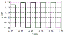
图5为基于单相桥式电容转换的混合储能脉冲电源转换电容电压和主开关电压曲线图。FIG. 5 is a graph showing the capacitor voltage and main switch voltage of the hybrid energy storage pulse power conversion based on single-phase bridge capacitor conversion.
图6为基于单相桥式电容转换的混合储能脉冲电源实施例2电路原理图。FIG. 6 is a circuit schematic diagram of Embodiment 2 of a hybrid energy storage pulse power supply based on single-phase bridge capacitor conversion.
具体实施方式Detailed ways
图1~5是本发明的最佳实施例,下面结合附图1~6对本发明做进一步说明。1 to 5 are the preferred embodiments of the present invention, and the present invention will be further described below in conjunction with the accompanying
如图1所示,一种基于单相桥式电容转换的混合储能脉冲电源,包括初级电源Us、晶闸管T1、单相桥式电容转换电路、耦合电感L1和L2、二极管D1以及负载R1,其中单相桥式电容转换电路由晶闸管T2~T5、可调电感Lc1~Lc2以及电容C1组成。As shown in Figure 1, a hybrid energy storage pulse power supply based on single-phase bridge capacitor conversion includes primary power supply Us, thyristor T1, single-phase bridge capacitor conversion circuit, coupled inductors L1 and L2, diode D1 and load R1, The single-phase bridge capacitor conversion circuit is composed of thyristor T2~T5, adjustable inductance Lc1~Lc2 and capacitor C1.
初级电源Us的正极与晶闸管T1的阳极连接,晶闸管T1的阴极同时连接单相桥式电容转换电路中晶闸管T2、晶闸管T4的阴极以及耦合电感L1的同名端。初级电源Us的负极同时连接单相桥式电容转换电路中晶闸管T3、晶闸管T5的阳极以及耦合电感L1的异名端。在单相桥式电容转换电路中,晶闸管T2的阳极串联可调电感Lc1之后同时连接晶闸管T3的阴极以及电容C1的一端,晶闸管T4的阳极串联可调电感Lc2之后同时连接晶闸管T5的阴极以及电容C1的另一端。The anode of the primary power supply Us is connected to the anode of the thyristor T1, and the cathode of the thyristor T1 is simultaneously connected to the thyristor T2, the cathode of the thyristor T4 and the same-named end of the coupled inductor L1 in the single-phase bridge capacitor conversion circuit. The negative pole of the primary power supply Us is simultaneously connected to the thyristor T3, the anode of the thyristor T5 and the opposite end of the coupled inductor L1 in the single-phase bridge capacitor conversion circuit. In the single-phase bridge capacitor conversion circuit, the anode of the thyristor T2 is connected in series with the adjustable inductance Lc1 and then connected to the cathode of the thyristor T3 and one end of the capacitor C1, and the anode of the thyristor T4 is connected in series with the adjustable inductance Lc2 and then connected to the cathode of the thyristor T5 and the capacitor at the same time. the other end of C1.
通过改变所述调节电感Lc1的大小,使主开关晶闸管T1在奇数次周期触发导通晶闸管T2、晶闸管T5时可靠关断;通过改变所述调节电感Lc2的大小,使主开关晶闸管T1在偶数次周期触发导通晶闸管T3、晶闸管T4时可靠关断。By changing the size of the adjusting inductance Lc1, the main switch thyristor T1 can be reliably turned off when the thyristor T2 and the thyristor T5 are turned on in odd cycles; The thyristor T3 and the thyristor T4 are reliably turned off when the cycle triggers turn on.
与耦合电感L1相互耦合的耦合电感L2的一端连接二极管D1的阴极,二极管D1的阳极串联负载R1之后连接耦合电感L2的另一端。所述耦合电感L1和耦合电感L2的耦合系数大于0.9,以增强等效电感,提高能量传输效率和利用率。One end of the coupled inductor L2 coupled with the coupled inductor L1 is connected to the cathode of the diode D1, and the anode of the diode D1 is connected to the other end of the coupled inductor L2 in series with the load R1. The coupling coefficient of the coupled inductance L1 and the coupled inductance L2 is greater than 0.9, so as to enhance the equivalent inductance and improve the energy transmission efficiency and utilization rate.
由本领域公知常识可知,晶闸管T1~T5均包括阳极、阴极和门极,当晶闸管的阳极也阴极之间存在正向电压的情况下,只有在给门极施加正向电压时晶闸管才会导通。此时晶闸管处于正向导通状态。而门极只是起到触发晶闸管的作用,即在晶闸管导通之后,只要晶闸管阳极和阴极之间存在一定的正向电压,不管门极电压如何变化,晶闸管始终保持导通状态。当晶闸管的阳极与阴极之间出现反向电压时,晶闸管关断。因此在现有技术中,虽然晶闸管相对于IGBT等其他开关器件在电流的通流能力以及成本上具有巨大优势,然而基于上述晶闸管的开关特性,在使用晶闸管作为开关元件时,需要同时配置较为复杂的外围电路实现晶闸管的关断,因此电路的复杂程度大大增加,同时系统的硬件成本也会相应上升,因此在一定程度上限制了晶闸管在脉冲功率技术领域的应用。It can be known from the common knowledge in the art that the thyristors T1 to T5 all include an anode, a cathode and a gate. When there is a forward voltage between the anode and the cathode of the thyristor, the thyristor will be turned on only when a forward voltage is applied to the gate. . At this time, the thyristor is in the forward conduction state. The gate only plays the role of triggering the thyristor, that is, after the thyristor is turned on, as long as there is a certain forward voltage between the anode and the cathode of the thyristor, no matter how the gate voltage changes, the thyristor always remains on. When a reverse voltage occurs between the anode and cathode of the thyristor, the thyristor turns off. Therefore, in the prior art, although thyristors have huge advantages in current flow capacity and cost compared to other switching devices such as IGBTs, based on the switching characteristics of the above thyristors, when using thyristors as switching elements, it needs to be configured at the same time. Therefore, the complexity of the circuit is greatly increased, and the hardware cost of the system will also increase accordingly, thus limiting the application of thyristors in the field of pulse power technology to a certain extent.
如图1所示的基于单相桥式电容转换的混合储能脉冲电源的工作过程及工作原理如下:As shown in Figure 1, the working process and working principle of the hybrid energy storage pulse power supply based on single-phase bridge capacitor conversion are as follows:
在本基于单相桥式电容转换的混合储能脉冲电源首次工作之前,需要对所述转换电容C1进行预充电,其中转换电容C1与晶闸管T3连接的一端预充正压,所述转换电容与晶闸管T5连接的一端预充负压。在单相桥式电容转换电路中,晶闸管T2和晶闸管T5组成单相桥式电容转换电路的一条桥臂,晶闸管T3和晶闸管T4组成单相桥式电容转换电路的另一条桥臂,两桥臂在奇偶次放电周期中交替导通,其中晶闸管T2和晶闸管T5所在的桥臂在奇数次放电周期中导通,晶闸管T3和晶闸管T4所在的桥臂在偶数次放电周期中导通。Before the hybrid energy storage pulse power supply based on single-phase bridge capacitor conversion works for the first time, the conversion capacitor C1 needs to be precharged, wherein the end of the conversion capacitor C1 connected to the thyristor T3 is precharged with positive voltage, and the conversion capacitor is connected to the thyristor T3. One end connected to the thyristor T5 is precharged with negative pressure. In the single-phase bridge capacitor conversion circuit, thyristor T2 and thyristor T5 form one bridge arm of the single-phase bridge capacitor conversion circuit, and thyristor T3 and thyristor T4 form the other bridge arm of the single-phase bridge capacitor conversion circuit. It is alternately turned on in odd and even discharge cycles, wherein the bridge arm where thyristor T2 and thyristor T5 are located is turned on in odd number of discharge cycles, and the bridge arm where thyristor T3 and thyristor T4 are located is turned on in even number of discharge cycles.
奇数次放电周期工作过程:Odd discharge cycle working process:
步骤a1,触发导通晶闸管T1,初级电源Us为耦合电感L1充电,同时阻断上一放电周期负载电流并回收负载侧剩余能量。当耦合电感L1电流到达预定值时,进入步骤b1;In step a1, the thyristor T1 is triggered and turned on, and the primary power supply Us charges the coupled inductor L1, and at the same time blocks the load current of the previous discharge cycle and recovers the remaining energy on the load side. When the current of the coupled inductor L1 reaches the predetermined value, go to step b1;
步骤b1,触发导通晶闸管T2、晶闸管T5,转换电容C1继续为耦合电感L1充电;此时转换电容C1的电压为左侧正极性右侧负极性,主开关晶闸管T1电流为零,且受到转换电容C1的反向电压关断;当转换电容C1的电压逐渐减小到零时,进入步骤c1;In step b1, the thyristor T2 and the thyristor T5 are triggered and turned on, and the switching capacitor C1 continues to charge the coupling inductor L1; at this time, the voltage of the switching capacitor C1 is positive on the left side and negative on the right side, the current of the main switch thyristor T1 is zero, and is converted The reverse voltage of the capacitor C1 is turned off; when the voltage of the conversion capacitor C1 gradually decreases to zero, enter step c1;
步骤c1,耦合电感L1开始为转换电容C1反向充电,转换电容C1的极性反转为左侧负极性右侧正极性;负载侧耦合电感L2的异名端为正极性,耦合电感L2开始对负载R1放电;当耦合电感L1的电流减小到零时,晶闸管T2和晶闸管T5受到转换电容C1的反向电压而关断,进入步骤d1;In step c1, the coupling inductor L1 starts to reversely charge the conversion capacitor C1, and the polarity of the conversion capacitor C1 is reversed to the left negative polarity and the right positive polarity; the opposite end of the load side coupling inductor L2 is positive polarity, and the coupling inductor L2 starts Discharge the load R1; when the current of the coupling inductor L1 is reduced to zero, the thyristor T2 and the thyristor T5 are turned off by the reverse voltage of the conversion capacitor C1, and enter step d1;
步骤d1,负载侧依照一阶RL指数规律衰减放电;负载脉冲宽度达到预定要求时,进入偶数次放电周期依次从步骤a2进行。In step d1, the load side decays and discharges according to the first-order RL exponential law; when the load pulse width reaches a predetermined requirement, it enters into even-numbered discharge cycles and proceeds sequentially from step a2.
偶数次放电周期工作过程:The working process of even-numbered discharge cycles:
步骤a2,触发导通晶闸管T1,初级电源Us为所述耦合电感L1充电,同时阻断上一放电周期负载电流并回收负载侧剩余能量。当耦合电感L1电流到达预定值时,进入步骤b2;In step a2, the thyristor T1 is triggered and turned on, and the primary power supply Us charges the coupled inductor L1, while blocking the load current in the previous discharge cycle and recovering the remaining energy on the load side. When the current of the coupled inductor L1 reaches the predetermined value, go to step b2;
步骤b2,触发导通晶闸管T3、晶闸管T4,转换电容C1继续为耦合电感L1充电;此时转换电容C1的电压为左侧负极性右侧正极性,主开关T1电流为零,且受到转换电容C1的反向电压关断;当转换电容C1的电压逐渐减小到零时,进入步骤c2;In step b2, the thyristor T3 and the thyristor T4 are triggered and turned on, and the switching capacitor C1 continues to charge the coupling inductor L1; at this time, the voltage of the switching capacitor C1 is negative on the left side and positive on the right side, and the current of the main switch T1 is zero, and is subjected to the switching capacitor. The reverse voltage of C1 is turned off; when the voltage of the conversion capacitor C1 gradually decreases to zero, enter step c2;
步骤c2,耦合电感L1开始为转换电容C1反向充电,转换电容C1的极性反转为左侧正极性右侧负极性;负载侧耦合电感L2的异名端为正极性,耦合电感L2开始对负载放电;当耦合电感L1的电流减小到零时,晶闸管T3、晶闸管T4受到转换电容C1的反向电压而关断,进入步骤d2;In step c2, the coupling inductor L1 begins to reversely charge the conversion capacitor C1, and the polarity of the conversion capacitor C1 is reversed to the positive polarity on the left and the negative polarity on the right; the opposite end of the coupling inductor L2 on the load side is positive, and the coupling inductor L2 starts Discharge the load; when the current of the coupling inductor L1 decreases to zero, the thyristor T3 and the thyristor T4 are turned off by the reverse voltage of the conversion capacitor C1, and enter step d2;
步骤d2,负载侧依照一阶RL指数规律衰减放电;负载脉冲宽度达到预定要求时,进入奇数次放电周期依次从步骤a1进行。In step d2, the load side decays and discharges according to the first-order RL exponential law; when the load pulse width reaches a predetermined requirement, it enters an odd-numbered discharge cycle and proceeds sequentially from step a1.
在本基于单相桥式电容转换的混合储能脉冲电源进行上述的奇数次放电周期和偶数次放电周期工作过程中,耦合电感L1中电流波形如图2所示,输出负载R1中电流曲线如图3所示,转换电容C1在多周期中电压曲线如图4所示,转换电容C1和主开关电压的曲线如图5所示,在图5中,曲线a表示转换电容电压曲线,曲线b表示主开关电压曲线。During the operation of the above-mentioned odd-numbered discharge cycles and even-numbered discharge cycles of the hybrid energy storage pulse power supply based on single-phase bridge capacitor conversion, the current waveform in the coupled inductor L1 is shown in Figure 2, and the current curve in the output load R1 is as follows As shown in Figure 3, the voltage curve of the switching capacitor C1 in multiple cycles is shown in Figure 4, and the curves of the switching capacitor C1 and the main switch voltage are shown in Figure 5. In Figure 5, the curve a represents the voltage curve of the switching capacitor, and the curve b Indicates the main switching voltage curve.
在本基于单相桥式电容转换的混合储能脉冲电源中,通过采用晶闸管作为主开关,可使系统具有较高的通流能力和较低的成本;在连续放电时,所述转换电容C1可回收耦合电感之间的漏感能量,并用于下一个放电周期中主开关晶闸管T1的电流过零关断;通过改变调节电感的大小,可对晶闸管T1的过零电流进行调节;在负载脉冲宽度达到要求时,通过触发晶闸管T1导通,可使初级电源Us对耦合电感L1充电的同时又可阻断负载电流脉冲,使负载侧剩余能量转移至L1中,可缩短新的工作周期的充电时间并提高整个系统的能量利用效率。In this hybrid energy storage pulse power supply based on single-phase bridge capacitor conversion, by using thyristor as the main switch, the system can have higher current capacity and lower cost; during continuous discharge, the conversion capacitor C1 The leakage inductance energy between the coupled inductors can be recovered and used for the current zero-crossing turn-off of the main switching thyristor T1 in the next discharge cycle; by changing the size of the adjustment inductance, the zero-crossing current of the thyristor T1 can be adjusted; When the width reaches the requirement, by triggering the thyristor T1 to turn on, the primary power supply Us can charge the coupled inductor L1 while blocking the load current pulse, so that the residual energy on the load side is transferred to L1, which can shorten the charging of the new working cycle. time and improve the energy efficiency of the entire system.
在本基于单相桥式电容转换的混合储能脉冲电源中,通过电容转换电路使主开关晶闸管过零关断,晶闸管和转换电容C1构成的单向桥式电容转换电路能够通过两桥臂上晶闸管周期性交替工作来收集耦合电感的漏感能量,并用于下一个放电周期中对晶闸管T1反向关断,提高了能量的利用效率。因此在本基于单相桥式电容转换的混合储能脉冲电源中,首先利用了晶闸管对于电流具有较大通流能力的特性,提高了整个系统的电流通过能力,同时利用转换电容C1给予晶闸管的反向电压使晶闸管关断,因此无需针对晶闸管设计相应的外围电路,因此电路的复杂程度大大降低,同时系统的硬件成本也大大降低。改变所述调节电感Lc1和调节电感Lc2的大小,使主开关晶闸管T1可靠关断。In this hybrid energy storage pulse power supply based on single-phase bridge capacitor conversion, the main switch thyristor is turned off by zero-crossing through the capacitor conversion circuit, and the one-way bridge capacitor conversion circuit composed of the thyristor and the conversion capacitor C1 The thyristor works alternately periodically to collect the leakage inductance energy of the coupled inductance, and is used to reversely turn off the thyristor T1 in the next discharge cycle, which improves the energy utilization efficiency. Therefore, in this hybrid energy storage pulse power supply based on single-phase bridge capacitor conversion, the characteristics of the thyristor having a large current capacity for current are first used to improve the current capacity of the entire system, and the conversion capacitor C1 is used to give the thyristor the reverse power. The thyristor is turned off by the voltage, so there is no need to design a corresponding peripheral circuit for the thyristor, so the complexity of the circuit is greatly reduced, and the hardware cost of the system is also greatly reduced. By changing the size of the adjusting inductance Lc1 and adjusting inductance Lc2, the main switch thyristor T1 can be turned off reliably.
实施例2:Example 2:
本实施例与实施例1的区别在于:在本实施例中,将耦合电感L1~L2的耦合方式设置为两顺向串联且具有高耦合系数的电感结构,如图6所示:初级电源Us的正极与晶闸管T1的阳极连接,晶闸管T1的阴极同时连接单相桥式电容转换电路中晶闸管T2、晶闸管T4的阴极以及耦合电感L1的同名端。The difference between this embodiment and
耦合电感L1的异名端同时连接二极管D1的阴极以及耦合电感L2的同名端,二极管D1的阳极连接负载R1的一端,负载R1的另一端与耦合电感L2的异名端以及单相桥式电容转换电路中晶闸管T3、晶闸管T5的阳极同时连接初级电源Us的负极。The synonymous end of the coupling inductor L1 is connected to the cathode of the diode D1 and the synonymous end of the coupling inductor L2 at the same time, the anode of the diode D1 is connected to one end of the load R1, the other end of the load R1 is connected to the synonymous end of the coupling inductor L2 and the single-phase bridge capacitor The anodes of the thyristor T3 and the thyristor T5 in the conversion circuit are simultaneously connected to the cathode of the primary power supply Us.
在单相桥式电容转换电路中,晶闸管T2的阳极串联可调电感Lc1之后同时连接晶闸管T3的阴极以及电容C1的一端,晶闸管T4的阳极串联可调电感Lc13之后同时连接晶闸管T5的阴极以及电容C1的另一端。In the single-phase bridge capacitor conversion circuit, the anode of the thyristor T2 is connected in series with the adjustable inductance Lc1 and then connected to the cathode of the thyristor T3 and one end of the capacitor C1, and the anode of the thyristor T4 is connected in series with the adjustable inductance Lc13 and then simultaneously connected to the cathode of the thyristor T5 and the capacitor. the other end of C1.
本实施例的电路结构的工作过程及原理如下与实施例1所示的电路相同,在此不再赘述。The working process and principle of the circuit structure of this embodiment are the same as the circuit shown in
以上所述,仅是本发明的较佳实施例而已,并非是对本发明作其它形式的限制,任何熟悉本专业的技术人员可能利用上述揭示的技术内容加以变更或改型为等同变化的等效实施例。但是凡是未脱离本发明技术方案内容,依据本发明的技术实质对以上实施例所作的任何简单修改、等同变化与改型,仍属于本发明技术方案的保护范围。The above are only preferred embodiments of the present invention, and are not intended to limit the present invention in other forms. Any person skilled in the art may use the technical content disclosed above to make changes or modifications to equivalent changes. Example. However, any simple modifications, equivalent changes and modifications made to the above embodiments according to the technical essence of the present invention without departing from the content of the technical solutions of the present invention still belong to the protection scope of the technical solutions of the present invention.
Claims (6)
Priority Applications (1)
| Application Number | Priority Date | Filing Date | Title |
|---|---|---|---|
| CN201811571656.3A CN109510504B (en) | 2018-12-21 | 2018-12-21 | A hybrid energy storage pulse power supply based on single-phase bridge capacitor conversion |
Applications Claiming Priority (1)
| Application Number | Priority Date | Filing Date | Title |
|---|---|---|---|
| CN201811571656.3A CN109510504B (en) | 2018-12-21 | 2018-12-21 | A hybrid energy storage pulse power supply based on single-phase bridge capacitor conversion |
Publications (2)
| Publication Number | Publication Date |
|---|---|
| CN109510504A CN109510504A (en) | 2019-03-22 |
| CN109510504B true CN109510504B (en) | 2020-11-27 |
Family
ID=65754127
Family Applications (1)
| Application Number | Title | Priority Date | Filing Date |
|---|---|---|---|
| CN201811571656.3A Active CN109510504B (en) | 2018-12-21 | 2018-12-21 | A hybrid energy storage pulse power supply based on single-phase bridge capacitor conversion |
Country Status (1)
| Country | Link |
|---|---|
| CN (1) | CN109510504B (en) |
Families Citing this family (4)
| Publication number | Priority date | Publication date | Assignee | Title |
|---|---|---|---|---|
| CN112398362B (en) * | 2019-08-14 | 2021-12-14 | 清华大学 | Capacitor self-charging pulse power supply circuit and pulse power supply |
| CN110993478A (en) | 2019-12-18 | 2020-04-10 | 北京北方华创微电子装备有限公司 | Pulse power supply control circuit and semiconductor processing equipment |
| CN113315429B (en) * | 2021-06-11 | 2022-10-18 | 山东理工大学 | Initial excitation circuit of a self-excited hollow pulse generator capable of recovering residual magnetic energy |
| CN113315427B (en) * | 2021-06-11 | 2022-10-18 | 山东理工大学 | Separately excited hollow pulse generator excitation circuit capable of recycling residual excitation energy |
Family Cites Families (4)
| Publication number | Priority date | Publication date | Assignee | Title |
|---|---|---|---|---|
| SU454652A1 (en) * | 1971-03-09 | 1974-12-25 | Ленинградский Политехнический Институт Им.М.И.Калинина | Serial single-phase bridge inverter |
| CN2852523Y (en) * | 2005-11-22 | 2006-12-27 | 福建龙净环保股份有限公司 | High-frequency high-voltage power supply for electrical dust collection |
| CN105515391B (en) * | 2016-01-20 | 2018-03-20 | 山东理工大学 | A kind of modularization superconducting energy storage continuous impulse power power-supply |
| CN108183700B (en) * | 2018-01-23 | 2021-01-05 | 山东理工大学 | Multi-module mode superconducting energy storage repetition frequency pulse power supply |
-
2018
- 2018-12-21 CN CN201811571656.3A patent/CN109510504B/en active Active
Also Published As
| Publication number | Publication date |
|---|---|
| CN109510504A (en) | 2019-03-22 |
Similar Documents
| Publication | Publication Date | Title |
|---|---|---|
| CN109510504B (en) | A hybrid energy storage pulse power supply based on single-phase bridge capacitor conversion | |
| CN105897033B (en) | A kind of capacitance multiplexing type inductive energy storage type pulse power for Electromagnetic Launching | |
| CN105281289A (en) | Bidirectional combined type direct current breaker and control method thereof | |
| CN103546057B (en) | A kind of repetition pulse power power-supply based on force the pass break bridge convertor | |
| CN101702578A (en) | Coupled Inductor Realizes Forward and Flyback Isolated Boost Converter and Its Application | |
| CN106655872B (en) | A series transformer type LLC positive and negative pulse dual battery charging power supply system | |
| CN100541993C (en) | Bidirectional three-level soft switching DC/DC for superconducting energy storage | |
| CN106487232B (en) | A ZVS Isolated Three-Level Buck Converter | |
| CN103501109A (en) | Converter bridge arm circuit with energy active feedback absorption loop and converter | |
| CN111817566A (en) | A LLCT resonant bidirectional DC converter | |
| CN105406724A (en) | Phase-shifting control full-bridge zero-current converter and direct-current switching power source | |
| CN105932898B (en) | A kind of hybrid inductive energy storage type pulse power of capacitance for Electromagnetic Launching | |
| CN102832844A (en) | Pulse power source utilizing double capacitors to discharge convertibly | |
| CN104617807A (en) | Inductive energy storing type pulse power supply for electromagnetic emission | |
| CN104935173B (en) | A kind of current source type full bridge PWM converter with auxiliary converter circuit | |
| CN107086785A (en) | A Soft-switching Implementation Method of Single-phase High-Gain Boost Converter | |
| CN105978372B (en) | A kind of topological circuit and half-bridge topology circuit and three phase full bridge topological circuit | |
| CN109713929B (en) | Three-phase three-switch two-level rectifier based on zero-voltage soft switch | |
| CN205429693U (en) | Two -way composite direct current breaker | |
| CN104601034B (en) | A kind of multimode pulse power based on high-temperature superconductor pulse transformer energy storage | |
| CN206564548U (en) | A kind of series transformer formula LLC positive negative pulse stuffings double cell charging power-supply system | |
| CN213461541U (en) | Soft switching motor drive circuit topology circuit | |
| CN110880883B (en) | A kind of inductive energy storage pulse power supply with energy recovery | |
| CN210075085U (en) | A Superconducting Magnet Power Supply Using Soft Switch Control | |
| CN104242666A (en) | Novel inverter welding power supply |
Legal Events
| Date | Code | Title | Description |
|---|---|---|---|
| PB01 | Publication | ||
| PB01 | Publication | ||
| SE01 | Entry into force of request for substantive examination | ||
| SE01 | Entry into force of request for substantive examination | ||
| GR01 | Patent grant | ||
| GR01 | Patent grant |