CN109478053B - System and method for additive manufacturing of transport structures - Google Patents
System and method for additive manufacturing of transport structures Download PDFInfo
- Publication number
- CN109478053B CN109478053B CN201780044765.7A CN201780044765A CN109478053B CN 109478053 B CN109478053 B CN 109478053B CN 201780044765 A CN201780044765 A CN 201780044765A CN 109478053 B CN109478053 B CN 109478053B
- Authority
- CN
- China
- Prior art keywords
- component
- analysis
- vehicle
- design
- components
- Prior art date
- Legal status (The legal status is an assumption and is not a legal conclusion. Google has not performed a legal analysis and makes no representation as to the accuracy of the status listed.)
- Active
Links
Images


Classifications
-
- G—PHYSICS
- G06—COMPUTING OR CALCULATING; COUNTING
- G06F—ELECTRIC DIGITAL DATA PROCESSING
- G06F30/00—Computer-aided design [CAD]
- G06F30/20—Design optimisation, verification or simulation
-
- B—PERFORMING OPERATIONS; TRANSPORTING
- B22—CASTING; POWDER METALLURGY
- B22F—WORKING METALLIC POWDER; MANUFACTURE OF ARTICLES FROM METALLIC POWDER; MAKING METALLIC POWDER; APPARATUS OR DEVICES SPECIALLY ADAPTED FOR METALLIC POWDER
- B22F10/00—Additive manufacturing of workpieces or articles from metallic powder
- B22F10/20—Direct sintering or melting
- B22F10/28—Powder bed fusion, e.g. selective laser melting [SLM] or electron beam melting [EBM]
-
- B—PERFORMING OPERATIONS; TRANSPORTING
- B22—CASTING; POWDER METALLURGY
- B22F—WORKING METALLIC POWDER; MANUFACTURE OF ARTICLES FROM METALLIC POWDER; MAKING METALLIC POWDER; APPARATUS OR DEVICES SPECIALLY ADAPTED FOR METALLIC POWDER
- B22F10/00—Additive manufacturing of workpieces or articles from metallic powder
- B22F10/80—Data acquisition or data processing
-
- B—PERFORMING OPERATIONS; TRANSPORTING
- B29—WORKING OF PLASTICS; WORKING OF SUBSTANCES IN A PLASTIC STATE IN GENERAL
- B29C—SHAPING OR JOINING OF PLASTICS; SHAPING OF MATERIAL IN A PLASTIC STATE, NOT OTHERWISE PROVIDED FOR; AFTER-TREATMENT OF THE SHAPED PRODUCTS, e.g. REPAIRING
- B29C64/00—Additive manufacturing, i.e. manufacturing of three-dimensional [3D] objects by additive deposition, additive agglomeration or additive layering, e.g. by 3D printing, stereolithography or selective laser sintering
- B29C64/30—Auxiliary operations or equipment
- B29C64/386—Data acquisition or data processing for additive manufacturing
-
- B—PERFORMING OPERATIONS; TRANSPORTING
- B29—WORKING OF PLASTICS; WORKING OF SUBSTANCES IN A PLASTIC STATE IN GENERAL
- B29D—PRODUCING PARTICULAR ARTICLES FROM PLASTICS OR FROM SUBSTANCES IN A PLASTIC STATE
- B29D12/00—Producing frames
-
- B—PERFORMING OPERATIONS; TRANSPORTING
- B33—ADDITIVE MANUFACTURING TECHNOLOGY
- B33Y—ADDITIVE MANUFACTURING, i.e. MANUFACTURING OF THREE-DIMENSIONAL [3-D] OBJECTS BY ADDITIVE DEPOSITION, ADDITIVE AGGLOMERATION OR ADDITIVE LAYERING, e.g. BY 3-D PRINTING, STEREOLITHOGRAPHY OR SELECTIVE LASER SINTERING
- B33Y10/00—Processes of additive manufacturing
-
- B—PERFORMING OPERATIONS; TRANSPORTING
- B33—ADDITIVE MANUFACTURING TECHNOLOGY
- B33Y—ADDITIVE MANUFACTURING, i.e. MANUFACTURING OF THREE-DIMENSIONAL [3-D] OBJECTS BY ADDITIVE DEPOSITION, ADDITIVE AGGLOMERATION OR ADDITIVE LAYERING, e.g. BY 3-D PRINTING, STEREOLITHOGRAPHY OR SELECTIVE LASER SINTERING
- B33Y30/00—Apparatus for additive manufacturing; Details thereof or accessories therefor
-
- B—PERFORMING OPERATIONS; TRANSPORTING
- B33—ADDITIVE MANUFACTURING TECHNOLOGY
- B33Y—ADDITIVE MANUFACTURING, i.e. MANUFACTURING OF THREE-DIMENSIONAL [3-D] OBJECTS BY ADDITIVE DEPOSITION, ADDITIVE AGGLOMERATION OR ADDITIVE LAYERING, e.g. BY 3-D PRINTING, STEREOLITHOGRAPHY OR SELECTIVE LASER SINTERING
- B33Y50/00—Data acquisition or data processing for additive manufacturing
- B33Y50/02—Data acquisition or data processing for additive manufacturing for controlling or regulating additive manufacturing processes
-
- G—PHYSICS
- G05—CONTROLLING; REGULATING
- G05B—CONTROL OR REGULATING SYSTEMS IN GENERAL; FUNCTIONAL ELEMENTS OF SUCH SYSTEMS; MONITORING OR TESTING ARRANGEMENTS FOR SUCH SYSTEMS OR ELEMENTS
- G05B19/00—Programme-control systems
- G05B19/02—Programme-control systems electric
- G05B19/18—Numerical control [NC], i.e. automatically operating machines, in particular machine tools, e.g. in a manufacturing environment, so as to execute positioning, movement or co-ordinated operations by means of programme data in numerical form
- G05B19/4097—Numerical control [NC], i.e. automatically operating machines, in particular machine tools, e.g. in a manufacturing environment, so as to execute positioning, movement or co-ordinated operations by means of programme data in numerical form characterised by using design data to control NC machines, e.g. CAD/CAM
- G05B19/4099—Surface or curve machining, making 3D objects, e.g. desktop manufacturing
-
- G—PHYSICS
- G06—COMPUTING OR CALCULATING; COUNTING
- G06F—ELECTRIC DIGITAL DATA PROCESSING
- G06F30/00—Computer-aided design [CAD]
- G06F30/10—Geometric CAD
- G06F30/15—Vehicle, aircraft or watercraft design
-
- G—PHYSICS
- G06—COMPUTING OR CALCULATING; COUNTING
- G06F—ELECTRIC DIGITAL DATA PROCESSING
- G06F30/00—Computer-aided design [CAD]
- G06F30/10—Geometric CAD
- G06F30/17—Mechanical parametric or variational design
-
- G—PHYSICS
- G06—COMPUTING OR CALCULATING; COUNTING
- G06F—ELECTRIC DIGITAL DATA PROCESSING
- G06F30/00—Computer-aided design [CAD]
- G06F30/20—Design optimisation, verification or simulation
- G06F30/28—Design optimisation, verification or simulation using fluid dynamics, e.g. using Navier-Stokes equations or computational fluid dynamics [CFD]
-
- B—PERFORMING OPERATIONS; TRANSPORTING
- B22—CASTING; POWDER METALLURGY
- B22F—WORKING METALLIC POWDER; MANUFACTURE OF ARTICLES FROM METALLIC POWDER; MAKING METALLIC POWDER; APPARATUS OR DEVICES SPECIALLY ADAPTED FOR METALLIC POWDER
- B22F10/00—Additive manufacturing of workpieces or articles from metallic powder
- B22F10/30—Process control
- B22F10/36—Process control of energy beam parameters
-
- B—PERFORMING OPERATIONS; TRANSPORTING
- B22—CASTING; POWDER METALLURGY
- B22F—WORKING METALLIC POWDER; MANUFACTURE OF ARTICLES FROM METALLIC POWDER; MAKING METALLIC POWDER; APPARATUS OR DEVICES SPECIALLY ADAPTED FOR METALLIC POWDER
- B22F12/00—Apparatus or devices specially adapted for additive manufacturing; Auxiliary means for additive manufacturing; Combinations of additive manufacturing apparatus or devices with other processing apparatus or devices
- B22F12/40—Radiation means
- B22F12/49—Scanners
-
- B—PERFORMING OPERATIONS; TRANSPORTING
- B22—CASTING; POWDER METALLURGY
- B22F—WORKING METALLIC POWDER; MANUFACTURE OF ARTICLES FROM METALLIC POWDER; MAKING METALLIC POWDER; APPARATUS OR DEVICES SPECIALLY ADAPTED FOR METALLIC POWDER
- B22F12/00—Apparatus or devices specially adapted for additive manufacturing; Auxiliary means for additive manufacturing; Combinations of additive manufacturing apparatus or devices with other processing apparatus or devices
- B22F12/50—Means for feeding of material, e.g. heads
- B22F12/52—Hoppers
-
- B—PERFORMING OPERATIONS; TRANSPORTING
- B22—CASTING; POWDER METALLURGY
- B22F—WORKING METALLIC POWDER; MANUFACTURE OF ARTICLES FROM METALLIC POWDER; MAKING METALLIC POWDER; APPARATUS OR DEVICES SPECIALLY ADAPTED FOR METALLIC POWDER
- B22F12/00—Apparatus or devices specially adapted for additive manufacturing; Auxiliary means for additive manufacturing; Combinations of additive manufacturing apparatus or devices with other processing apparatus or devices
- B22F12/90—Means for process control, e.g. cameras or sensors
-
- G—PHYSICS
- G05—CONTROLLING; REGULATING
- G05B—CONTROL OR REGULATING SYSTEMS IN GENERAL; FUNCTIONAL ELEMENTS OF SUCH SYSTEMS; MONITORING OR TESTING ARRANGEMENTS FOR SUCH SYSTEMS OR ELEMENTS
- G05B2219/00—Program-control systems
- G05B2219/30—Nc systems
- G05B2219/49—Nc machine tool, till multiple
- G05B2219/49023—3-D printing, layer of powder, add drops of binder in layer, new powder
-
- G—PHYSICS
- G06—COMPUTING OR CALCULATING; COUNTING
- G06F—ELECTRIC DIGITAL DATA PROCESSING
- G06F2113/00—Details relating to the application field
- G06F2113/10—Additive manufacturing, e.g. 3D printing
-
- Y—GENERAL TAGGING OF NEW TECHNOLOGICAL DEVELOPMENTS; GENERAL TAGGING OF CROSS-SECTIONAL TECHNOLOGIES SPANNING OVER SEVERAL SECTIONS OF THE IPC; TECHNICAL SUBJECTS COVERED BY FORMER USPC CROSS-REFERENCE ART COLLECTIONS [XRACs] AND DIGESTS
- Y02—TECHNOLOGIES OR APPLICATIONS FOR MITIGATION OR ADAPTATION AGAINST CLIMATE CHANGE
- Y02P—CLIMATE CHANGE MITIGATION TECHNOLOGIES IN THE PRODUCTION OR PROCESSING OF GOODS
- Y02P10/00—Technologies related to metal processing
- Y02P10/25—Process efficiency
Landscapes
- Engineering & Computer Science (AREA)
- Physics & Mathematics (AREA)
- Manufacturing & Machinery (AREA)
- Chemical & Material Sciences (AREA)
- Materials Engineering (AREA)
- Geometry (AREA)
- General Physics & Mathematics (AREA)
- Theoretical Computer Science (AREA)
- Automation & Control Theory (AREA)
- Computer Hardware Design (AREA)
- Evolutionary Computation (AREA)
- General Engineering & Computer Science (AREA)
- Mathematical Analysis (AREA)
- Mathematical Optimization (AREA)
- Pure & Applied Mathematics (AREA)
- Computational Mathematics (AREA)
- Mechanical Engineering (AREA)
- Plasma & Fusion (AREA)
- Human Computer Interaction (AREA)
- Aviation & Aerospace Engineering (AREA)
- Optics & Photonics (AREA)
- Analytical Chemistry (AREA)
- Health & Medical Sciences (AREA)
- General Health & Medical Sciences (AREA)
- Toxicology (AREA)
- Fluid Mechanics (AREA)
- Computing Systems (AREA)
- Algebra (AREA)
- Mathematical Physics (AREA)
- Powder Metallurgy (AREA)
- Management, Administration, Business Operations System, And Electronic Commerce (AREA)
- Design And Manufacture Of Integrated Circuits (AREA)
- Seats For Vehicles (AREA)
- Stored Programmes (AREA)
- Lubricants (AREA)
- Detergent Compositions (AREA)
- Architecture (AREA)
- Software Systems (AREA)
Abstract
Systems and methods of additive manufacturing of a vehicle are provided. An additive manufacturing apparatus may include a printer to additively manufacture a structure of a vehicle and a plurality of analysis components. Each analysis component can receive information based on a design model of the vehicle and analyze the information based on analysis factors. Each analysis component analyzes the information based on different analysis factors. The integrator can receive the analyzed information from the analysis component, update the design model based on the analyzed information, and determine whether the updated design model satisfies the criteria. The integrator determines print instructions for causing the printer to print one or more structures of the vehicle based on the updated design model if the updated design model satisfies the criteria, and sends information based on the updated design model to the analysis component if the updated design model does not satisfy the criteria.
Description
Cross Reference to Related Applications
The benefit of U.S. provisional patent application No.62/340,930 entitled "SYSTEMS AND METHODS FOR generating optical properties FOR 3D-PRINTED STRUCTURES", filed 2016, 24/5/2016, which is expressly incorporated herein by reference in its entirety.
Technical Field
The present disclosure relates generally to additive manufacturing, and more particularly to Additive Manufacturing (AM) printers for vehicle manufacturing.
Background
Three-dimensional ("3-D") printed or additively manufactured structures have a wide range of engineering applications across a number of industries, including automotive, aerospace, marine, and the like. Modular construction using nodes or nodes is one example of a construction technique that may be used in vehicle design. This technique may yield advantages such as low tooling costs, design flexibility, and the ability to create highly efficient structures. The 3-D printed joints can be used for the attachment of standard structures and structural materials such as pipes, carbon plates and honeycomb plates. The joining of multiple non-standard, but low cost, high performance materials is also possible. For example, the joints may be printed according to specifications of geometric and physical requirements at each pipeline intersection.
However, as the complexity of 3-D printed designs increases, the complexity, requirements, or constraints (e.g., time, cost, manufacturing, etc.) associated with generating 3-D printed structures also become more complex. Existing topology optimization techniques may be inadequate for designing and manufacturing objects (e.g., vehicles) based on 3-D printed structures, given the complex, sometimes conflicting, design variables and goals that differ from conventional designs.
Disclosure of Invention
Several aspects of an additive manufacturing apparatus for manufacturing of transport structures, such as vehicle manufacturing, will be described more fully below.
In various aspects, an additive manufacturing apparatus may include a printer to additively manufacture a structure of a vehicle, a plurality of analysis components, each analysis component configured to receive information based on a design model of the vehicle and analyze the information based on analysis factors, wherein each analysis component analyzes the information based on analysis factors different from other analysis components, and an integrator to receive the analyzed information from the analysis components, update the design model based on the analyzed information, and determine whether an updated design model satisfies criteria, wherein if the updated design model satisfies the criteria, the integrator determines an instruction to cause the printer to print one or more structures of the vehicle based on the updated design model, and if the updated design model does not satisfy the criteria, the integrator sends the information based on the updated design model to the analysis components, the analysis component updates the information based on the updated design model.
In various aspects, a method of additive manufacturing may comprise: transmitting information based on the design model of the vehicle to a plurality of analysis components; receiving analyzed information from analysis components, wherein each analysis component analyzes the information based on different analysis factors than other analysis components; updating the design model based on the analyzed information; determining whether the updated design model satisfies a criterion; determining printing instructions for causing a printer to additively manufacture one or more structures of a vehicle based on the updated design model, printing the one or more structures based on the printing instructions if the updated design model satisfies the criteria, and sending information based on the updated design model to an analysis component if the updated design model does not satisfy the criteria, wherein the analysis component analyzes the information based on the updated design model.
In various aspects, a non-transitory computer-readable medium storing computer-executable instructions for additive manufacturing may include instructions executable to perform the steps of: transmitting information based on the design model of the vehicle to a plurality of analysis components; receiving analyzed information from analysis components, wherein each analysis component analyzes the information based on different analysis factors than other analysis components; updating the design model based on the analyzed information; determining whether the updated design model satisfies a criterion; determining printing instructions for causing a printer to additively manufacture one or more structures of a vehicle based on the updated design model, printing the one or more structures based on the printing instructions if the updated design model satisfies the criteria, and sending information based on the updated design model to an analysis component if the updated design model does not satisfy the criteria, wherein the analysis component analyzes the information based on the updated design model.
Other aspects will become readily apparent to those skilled in the art from the following description, wherein several embodiments are shown and described, simply by way of illustration. As those skilled in the art will recognize, the concepts herein are capable of other and different embodiments and several details are capable of modification in various other respects, all without departing from the disclosure. Accordingly, the drawings and detailed description are to be regarded as illustrative in nature and not as restrictive.
Drawings
In the drawings, aspects of an additive manufacturing apparatus for manufacturing a transport structure will now be presented by way of example and not limitation in the detailed description,
FIGS. 1A-D illustrate an example 3-D printer system during different phases of operation.
FIG. 2 illustrates an exemplary 3-D printer including multi-factor design integration.
FIG. 3 illustrates exemplary components of a design optimization system.
FIG. 4 illustrates an exemplary design improvement hierarchy.
FIG. 5 shows a list of exemplary factors that will be considered for vehicle chassis design.
FIG. 6 shows an exemplary schematic framework in a design optimization process that includes factors for various procedures.
FIG. 7 illustrates an example of a multi-objective optimization scenario and method of solving the problem.
FIG. 8 illustrates an exemplary multi-layer design process.
Fig. 9 shows an example of requirements involved in the design process.
FIG. 10A illustrates an example of a visual representation of concerns and trade-off options for a design that a user prefers to drive.
10B-C illustrate examples of design optimization on a level that prefers driving.
FIG. 10D illustrates an example of an apparatus that provides a graphical user interface and user interaction.
FIG. 11 shows a diagram of the data flow through an exemplary design optimization cycle.
FIG. 12 shows a rendering of an exemplary output of one cycle of a simulation test.
Fig. 13 shows a graph of exemplary performance test results evaluated by the optimality evaluation unit.
Fig. 14 illustrates an example of data contained in the database.
FIG. 15 illustrates an example of data from a manufacturing process and other processes.
FIG. 16 illustrates a schematic block diagram of an exemplary design optimization system.
17A-B illustrate exemplary modifications to elements of a vehicle front end structure to meet ground clearance criteria.
FIG. 18 illustrates an exemplary multi-factor integrated design process.
FIG. 19 is a flow chart illustrating an exemplary integrated design process.
Detailed Description
The detailed description set forth below in connection with the appended drawings is intended to provide a description of various exemplary embodiments of the concepts disclosed herein, and is not intended to represent the only embodiments in which the present disclosure may be practiced. The term "exemplary" as used in this disclosure means "serving as an example, instance, or illustration," and should not necessarily be construed as preferred or advantageous over other embodiments presented in this disclosure. The detailed description includes specific details for the purpose of providing a thorough, complete disclosure that fully convey the scope of the concept to those skilled in the art. However, the present disclosure may be practiced without these details. In some instances, well-known structures and components may be shown in block diagram form, or omitted entirely, in order to avoid obscuring the various concepts presented throughout this disclosure.
3-D printing technology may enable custom after-market parts for automobiles, trucks, boats, airplanes, etc. to be quickly and conveniently manufactured. For example, a racing team may decide after the first race of the season that, for example, a greater downward force needs to be generated by the rear wing. A new rear wing that generates a greater downward force can be quickly designed and printed for installation prior to the next game in the season. In other words, 3-D printing has greatly improved the ease and ability to design and manufacture individual vehicle parts that are typically designed to meet a limited number of narrow face of interest criteria (i.e., design goals) within a single analytical factor (i.e., design specification or domain). In the above example, the rear wing design of a racing team has focused on a single criterion within the analytical factors of aerodynamics, namely, downward force.
However, designing larger scale vehicle components (such as the chassis, passenger compartment, etc.), and particularly the entire vehicle, requires meeting a number of criteria. In these cases, a chimney approach is often used, where different factors (such as aerodynamics, durability, ergonomics, etc.) are analyzed by separate teams. Each team attempts to optimize criteria important to that team. For example, a collision team attempts to maximize the collision test score, while an aerodynamic team attempts to minimize the drag coefficient.
As guidelines become more and more complex due to, for example, increased government regulations, concern over environmental impact, etc., the chimney approach becomes less and less effective. In particular, current methods for designing vehicles have not expanded well as the number of criteria has increased. Such a chimney approach results in competition among teams, which may result in one team (i.e., analytical factor) dominating the design.
Various aspects of the present disclosure may, for example, provide integrated design optimization. In various aspects, a user may be provided autonomy to customize a target in several aspects.
In one aspect, the present disclosure provides a method that enables a design process for a 3-D printed structure to be customized and automated. The design system may be used for 3-D structured design. Most of the examples provided herein may refer to vehicles, however, the presented methods and systems may be widely applied across industries where 3-D printed structures form part of an overall product. For example, the 3-D printed structure may be a land-based, air-based, water-based, or space-based vehicle (e.g., a van, truck, bus, van, minivan, station wagon, camper (RV), trailer, tractor, walker, automobile, train, motorcycle, boat, spacecraft, airplane, etc.); a portion or subsystem of a vehicle, such as a vehicle body, chassis, panel, engine, etc.
In various embodiments, design goals may be based on 3-D printed nodes connected together with standard structural components and parts (such as pipes, sheets, arcs, honeycomb material, etc.). The nodes (e.g., joint members) may be configured to provide connections for a plurality of pipes that may be used to construct a lightweight space frame. The space frame may be a frame having a three-dimensional volume. The space frame may be a frame that can accept one or more panels to at least partially fit into the frame. An example of a space frame may be a vehicle chassis. In addition to other structures including node and structure based constructs, various aspects of the present disclosure may be applied to the applications identified herein. It should be understood that different aspects of the present disclosure may be utilized individually, collectively, or in combination with each other.
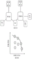
FIGS. 1A-D illustrate various side views of an exemplary 3-D printer system. In this example, the 3-D printer system is a Powder Bed Fusion (PBF) system 100. Fig. 1A-D illustrate the PBF system 100 during different stages of operation. The specific embodiment shown in fig. 1A-D is one of many suitable examples of a PBF system that employs the principles of the present disclosure. It should also be noted that the elements of fig. 1A-D and other figures in this disclosure are not necessarily drawn to scale, but may be drawn larger or smaller for the purpose of better illustrating the concepts described herein. The PBF system 100 can include a depositor 101, an energy beam source 103, a deflector 105, and a build plate 107, the depositor 101 can deposit each layer of metal powder, the energy beam source 103 can generate an energy beam, the deflector 105 can apply the energy beam to melt the powder material, and the build plate 107 can support one or more builds, such as build 109. PBF system 100 may also include a build floor 111 located within the powder bed vessel. The walls of the powder bed container 112 generally define the boundaries of the powder bed container, with the powder bed container 112 being sandwiched between the walls 112 from the sides and abutting an underlying portion of the build floor 111. The build floor 111 may progressively lower the build plate 107 so that the depositor 101 may deposit the next layer. The entire mechanism may reside in a chamber 113 that may house other components, protecting equipment, enabling aerodynamic and temperature regulation, and reducing contamination risks. The depositor 101 may include a hopper 115 and a leveler 119, the hopper 115 containing a powder 117, such as a metal powder, the leveler 119 may level the top of each layer of deposited powder.
With particular reference to FIG. 1A, the PBF system 100 is shown after a slice of the build 109 has been melted, but before the next layer of powder has been deposited. Indeed, fig. 1A illustrates the time at which the PBF system 100 has deposited and fused multiple layers of slices (e.g., 150 layers) to form the current state of the build 109 (e.g., formed from 105 slices). The already deposited layers create a powder bed 121, the powder bed 121 comprising deposited, but not melted powder.
Fig. 1B shows PBF system 100 at a stage where build floor 111 may reduce powder layer thickness 123. The lowering of the build floor 111 lowers the build 109 and powder bed 121 by the powder layer thickness 123 such that the top of the build and powder bed is lower than the top of the powder bed container wall 112 by an amount equal to the powder layer thickness. In this way, for example, a space having a uniform thickness equal to the powder layer thickness 123 may be created on top of the build piece 109 and the powder bed 121.
Fig. 1C shows the PBF system 100 at a stage when the depositor 101 is positioned to deposit powder 117 in the space created on the top surface of the build-up 109 and powder bed 121 and bounded by the powder bed container wall 112. In this example, the depositor 101 progressively moves over a defined space while releasing the powder 117 from the hopper 115. The leveler 119 may level the released powder to form a powder layer 125, the powder layer 125 having a thickness substantially equal to a powder layer thickness 123 (see fig. 1B). Thus, the powder in the PBF system may be supported by a powder material support structure, which may include, for example, a build plate 107, a build floor 111, a build 109, walls 112, and the like. It should be noted that the illustrated thickness of the powder layer 125 (i.e., the powder layer thickness 123 (fig. 1B)) is greater than the actual thickness for the example involving the 150 previously deposited layers discussed above with reference to fig. 1A.
Fig. 1D shows the PBF system 100 at a stage when the energy beam source 103 generates an energy beam 127 after deposition of the powder layer 125 (fig. 1C) and the deflector 105 applies the energy beam to melt the next slice in the build piece 109. In various exemplary embodiments, the energy beam source 103 may be an electron beam source, in which case the energy beam 127 constitutes an electron beam. The deflector 105 may include deflection plates that can generate electric or magnetic fields that selectively deflect the electron beam to scan the electron beam across the area designated for melting. In various embodiments, the energy beam source 103 may be a laser, in which case the energy beam 127 is a laser beam. The deflector 105 may include an optical system that uses reflection and/or refraction to steer the electron beam to scan a selected area to be melted.
In various embodiments, the deflector 105 may include one or more gimbal and actuator that may rotate and/or translate the energy beam source to position the energy beam. In various embodiments, the energy beam source 103 and/or the deflector 105 may modulate the energy beam, e.g. turn the energy beam on and off as the deflector scans such that the energy beam is applied only in suitable areas of the powder layer. For example, in various embodiments, the energy beam may be modulated by a Digital Signal Processor (DSP).
FIG. 2 illustrates an exemplary 3-D printer, e.g., PBF device 200, including multi-factor design integration. Fig. 2 shows a build plate 201, a powder bed 203 and a build piece 205. The energy application system 209 may apply energy to melt the powder material in the deposited powder layer. For illustrative purposes, the powder depositor is not shown in this figure. The energy application system 209 may comprise an energy applicator 210, the energy applicator 210 may comprise an energy beam source 211 and a deflector 213. The energy application system may also include computer memory 215, such as RAM, a computer storage disk, or the like. Memory 215 may store print instructions 217. The printing instructions 217 may include instructions for each powder layer in the printing process that may control how the energy beam source 211 and the deflector 213 scan each powder layer. For example, the print instructions 217 may control print parameters such as scan rate, beam power, location of beam melting, and the like.
In this example, the print instructions 217 may be determined by the integrator 219 based on a number of design factors. Specifically, integrator 219 may send information based on a design model of a vehicle or vehicle part (e.g., a component for a transport structure) to a plurality of analysis components, such as first analysis component 221, second analysis component 223, and nth analysis component 225. Each analysis component can modify the information based on the analysis factors corresponding to the analysis component. Each analysis component modifies the information based on different analysis factors than other analysis components. For example, the first analysis component 221 can analyze the information to determine the aerodynamic properties of the design model. In this case, the first analysis component may for example be a computer program that calculates aerodynamic properties based on external shape information of the design model. The second analysis component 223 can analyze the information to determine the durability of the design model. In this case, the second analysis component may be, for example, a computer program that calculates durability characteristics based on information of the materials currently selected for designing the various structures of the model. The analysis component may send the analyzed information to the integrator 219.
The integrator 219 can receive the analyzed information from the analysis component and update the design model based on the analyzed information. The integrator 219 may then determine whether the updated design model satisfies criteria for the vehicle. For example, the criteria may include a maximum aerodynamic drag coefficient with which the information returned by the aerodynamic analysis component will be most relevant. In another example, the criteria may include a minimum number of stress cycles before failure to which the information returned by the aerodynamic analysis component will be most relevant.
If the updated design model satisfies the criteria, the integrator 219 may determine print instructions 217 to cause the 3-D printer to print one or more structures of the vehicle based on the updated design model. On the other hand, if the updated design model does not satisfy the criteria, the integrator 219 may send information based on the updated design model to the analysis component. In such a case, the analysis component can analyze the information based on the updated design model. Thus, for example, the integrator 219 may integrate disparate analytical information into an updated design model to repeat the process to iteratively approach a state where all criteria are met if the updated design model does not meet all criteria for the vehicle.
FIG. 3 illustrates components of an exemplary multi-factor design integration system. The design integration system may include a plurality of design improvement levels 301. In some embodiments, multiple design improvement levels 301 for a design product may be performed using various analysis factors. In various embodiments, the analysis factors 303 may be analyzed and evaluated during design optimization across multiple design improvement levels 301. It should be understood that the term optimization herein includes customization or personalization of design choices, and may be used interchangeably throughout this description.
As shown in fig. 3, the design improvement level 301 may include a macro level, an intermediate level, and a micro level. For a vehicle structural design, the macro level may correspond to the vehicle level, the middle level may correspond to the node level, and the micro level may correspond to the material level. It should be noted that there are various ways to define the level and extent of design improvement. There may be more or less than three levels in topology optimization. In some embodiments, design improvement levels may be defined according to the modularity of the design product.
In some embodiments, one or more of the plurality of analysis factors 303 may or may not be based on physics, i.e., physical analysis. FIG. 3 shows a list of exemplary analysis factors 303 to be considered for vehicle design. Various analytical factors may include areas of consideration for vehicle design in traditional automotive engineering specifications, such as NVH (noise, vibration, and harshness), aerodynamics, fuel economy/emissions, durability/corrosion, packaging/ergonomics, vehicle dynamics, linear Finite Element Analysis (FEA)/stiffness, environmental impact, and the like. In addition, various analytical factors may also include elements related to 3-D printed structural design, such as node locations, composite materials, heat, and existing parts box/system costs. In some embodiments, these analytical factors may or may not be related to physics-based analysis, such that they may cover a wide range from the traditional basic rules domain (e.g., performance) as previously described to the life cycle domain (such as manufacturability, modeling, supportability, environmental impact, economics, cost, etc.).
In some embodiments, analysis factors may refer to design engineering attributes or procedures that may include components for simulation testing or analysis. The component may be configured to analyze products from a particular domain based on a mathematical model or an empirical model. The components within the simulation architecture may be implemented as computer code, such as the various software programs mentioned previously. The module may require one or more input variables of the design model and may produce a correlation output that is optimized towards or tested against a particular criterion or criteria.
In some embodiments, a component, which may be implemented as a software program or computer code, may be used to analyze or evaluate multiple analytical factors. Available CAD (computer aided design) and CAE (computer aided engineering) simulation analysis software programs and/or multi-physical quantity software packages may be used for various analysis factors.
In some embodiments, a plurality of analysis factors may be analyzed simultaneously using one or more multiple physical quantity models. Multiple physical methods (such as single discretization and/or multiple discretization methods) can involve analysis of multiple physical models or multiple simultaneous physical phenomena. Various open source software packages and commercially available software packages may be used to simulate a multiple physical quantity model (coupled physics) based on a finite element method or other common numerical methods.
In some embodiments, each analytical factor may be analyzed individually, and the analytical results from the various components may be integrated and evaluated using an integration procedure as described later herein.
Multiple variables may be involved in the design optimization process at each stage. In some embodiments, one or more variables may be simultaneously involved in an iteration of the design optimization process according to criteria for designing a product or layer.
The degree of design optimization may be based on modularity. In some embodiments, the present disclosure provides a design optimization method that may include modifications and iterations that improve multiple degrees or levels of a design during an optimization process.
In conventional design optimization processes, some aspects of the design model are typically fixed and difficult to alter or change compared to the design variables. However, the present disclosure may provide a method such that aspects of a 3-D printing structure based design may be altered and adjusted at various levels and the optimization results may be significantly improved. In some embodiments, different levels of design improvement may involve modifying and adjusting various properties of parts or components that may or may not be 3-D printed.
Fig. 4 illustrates an exemplary design improvement hierarchy 400. In some embodiments, the 3-D printing structure may be modified and/or optimized at different levels. Taking the 3-D printing node based structure as an example, three design improvement levels 400 for design improvement may be included in the topology optimization process as shown in fig. 4.
In some embodiments, the macro-level 401 optimization may include modifications and alterations at the structural level. For example, if the design product is a vehicle that includes multiple subassemblies or subsystems, the number and placement of the subassemblies or subsystem components in space may be varied during the macro-level 401 optimization. In another example of vehicle chassis design, the material topology can be tuned by 3-D printing the area and location of joints (nodes) to achieve optimal performance.
In some embodiments, the intermediate level 403 optimization may include modifications and alterations to components at the sub-structure level relative to the macro level 401. For example, for a vehicle chassis based on a 3-D printed node structure, the middle hierarchy 403 may refer to a node hierarchy. In this case, the node level optimization may improve various properties of the node, such as shape, size, structure, connection angle between the pipe and the joint, fine features (e.g., centering, connecting, and folding features), connecting and bonding materials, and the like.
In some embodiments, the micro-level 405 optimization may include modifications to the microstructural properties of the material. In some embodiments, the properties of the material may be on a millimeter or sub-millimeter scale. The properties of the material may include, but are not limited to, material type, layer thickness for bonding, porosity, alloys, impregnation, ion implantation, weave direction, skeletonization, pore filling, and the like. In some embodiments, intermediate hierarchy components (e.g., nodes, panels, nodes) may include internal structures. For example, panels may be formed by applying porosity, skeletonization, or forming internal honeycomb structures to reduce material volume, weight, or cost. When high strength, lightweight materials are desired to achieve fuel efficiency goals, honeycomb, foam, truss grid structures, and any other suitable 2-D or 3-D structures may be employed. The form of these microstructures can be optimized to provide certain performance benefits. For example, a 3-D Kagome lattice structure (originally as a weave pattern) may be identified by topological optimization as the best structure over other structures (e.g., tetrahedrons, pyramidal trusses, hexagons, etc.) based on its modulus of elasticity for a range of fractional volumes. The properties of the selected material may be further optimized by varying the size, materials, and arrangement of the components within the structure. Such 3-D printed structures and materials include those described in WO 2015/175892 entitled "modulated for devices and methods of us" and WO 2016/003982 entitled "Systems and methods for marking join members," which are incorporated herein by reference in their entirety.
It should be noted that there are various ways to define the level and extent of design improvement. In some embodiments, design improvement levels may be defined based on a particular design product. For example, if the design product is part of a vehicle chassis, the hierarchy may include only intermediate and micro-level improvements. In some embodiments, one or more variables and/or parameters from design models of different levels may or may not be modified simultaneously within an iteration cycle. Furthermore, topological optimization is discussed herein as an example, and additional structural optimization may also be involved, such as size, weight and stiffness, number, and shape optimization of the constituent elements.
In some embodiments, multiple analytical factors considered in designing and optimizing a 3-D structure-based object may be analyzed or optimized at multiple levels. FIG. 5 illustrates an exemplary relationship between a plurality of analysis factors 500 and a plurality of design improvement hierarchies 510.
The plurality of analytical factors may include design rules such as NVH (noise, vibration and harshness), aerodynamics, fuel economy/emissions, durability/corrosion, packaging/ergonomics, vehicle dynamics, linear FEA/stiffness, environmental impact, etc. In addition, various factors may also include elements related to 3-D printing, such as node location, composite material, heat, and existing parts box/system cost. These analytical factors may or may not be physics-based and may cover a wide range from the realm of traditional ground rules (e.g., performance) to the realm of life cycles (such as manufacturability, supportability, economics, cost, etc.).
In some embodiments, the plurality of analysis factors may include components that may be implemented as software programs or computer code. In some embodiments, multiple physical methods (such as single discretization and/or multiple discretization methods) can involve analysis of multiple physical models or multiple simultaneous physical phenomena.
Analysis of multiple factors may involve design optimization at various stages. In some embodiments, one or more of the factors may be simultaneously involved in an iteration of the design optimization process according to criteria for designing the product.
In some embodiments, the analysis method may use one or more modules. In some cases, a module may refer to a software program configured to analyze a single analysis factor. In other cases, a module may refer to a software program configured to analyze multiple factors during optimization. The module may be configured to analyze products from a particular domain based on a mathematical model or an empirical model. The modules within the simulation architecture may be implemented as computer code, such as the various software programs mentioned previously. A module may need to design one or more input variables of a model and produce a correlation output that is optimized towards or tested against a particular criterion.
In some embodiments, the one or more variables of the design model may be modified or adjusted at one or more design improvement levels. Multiple factors may be grouped together and optimized simultaneously. For example, as shown in FIG. 5, in an optimization iteration, multiple analytical factors may be analyzed and evaluated 501 simultaneously, while multiple variables of the model from one or more design improvement levels may be adjusted.
In some embodiments, multiple design analysis factors may be analyzed and optimized simultaneously (e.g., in parallel) in the design process. In some embodiments, an integrator that oversees the analysis and optimization of various analytical factors may be included.
FIG. 6 shows an exemplary schematic framework in a design optimization process that includes analytical factors for various protocols. Multiple analytical factors may be optimized or analyzed simultaneously. In various embodiments, these analysis factors may correspond to different design rules. In some embodiments, several analysis factors may be coupled together. In some cases, one analysis factor may be analyzed by a corresponding analysis component (such as aerodynamic analysis component 611, cost analysis component 613, and collision analysis component 615). In various embodiments, a single component may perform analysis of multiple factors.
In some embodiments, various components for analyzing various factors may be coupled or related. For example, an input variable of one component may be a constraint of another component that causes a feedback loop at the system level, total product level, and so forth. In some cases, these feedback loops may be induced within delay-causing iterations in the optimization process. The present disclosure may improve the design process by decoupling multiple analysis factors using multiple improvement levels as previously described. For example, the flexibility in selecting design variables may allow for optimal and efficient information flow during the iterative optimization process.
In some cases, the coupled analysis components may share the same design input variable x 601 with the criteria in the different analysis factors to be implemented. For example, the aerodynamic analysis module 611 may require variable x and constraints/requirements g1 and h1, the cost analysis module 613 may require the same design variable x and design target J2, and the collision analysis component 615 may require design variable x, design target J3, and constraints g3 and h 3. In some embodiments, the goals and constraints of multiple analytic factors (such as g1, h1, j2, j3, g3, and h3) may or may not be in conflict. Where conflicting optimization objectives exist, an integrator 600 that integrates the analysis components may be included. In various embodiments, integrator 600 may communicate with the user to decide a tradeoff between conflicting goals based on user preferences, if necessary.
In various embodiments, during optimization, the integrator 600 may communicate with a plurality of analysis factor modules. In some embodiments, the analysis factors module may be instructed by the integrator 600 to run tests to analyze one or more performance characteristics of a design under certain conditions and submit the analysis results to the integrator 600 for evaluation and decision-making. The integrator 600 may analyze the received individual analysis results and determine a new value for the design variable x, which may be designated as x'. The new value x' may then be provided to a plurality of analysis factor components to update the current design. Multiple iterations may be included until the result of the optimization is achieved. In some embodiments, the integrator 600 may record the design variables and analysis results for each version of the design model by storing the data in a database. For example, as shown in FIG. 6, the integrator 600 may instruct the aerodynamic analysis component 611 and the cost component 613 to run analysis and testing concurrently on the current design model. The test results from the aerodynamic analysis component 611 and the cost analysis component 613 may be sent to the integrator 600 for evaluation. Based on the evaluation of the integrated test results against the overall design criteria, the integrator can determine new values for variables (such as variable x) to update the current model, and instruct the analysis component to repeat the analysis based on the updated model. In some embodiments, one or more iterations may be performed until the result of the optimization is achieved.
In addition to analysis, multiple analysis components can optimize the current design model within each component such that the design model can be modified within each analysis component. Thus, the resulting optimized design model along with the test evaluations may be submitted to the integrator 600. In some cases, the analysis component may perform the tests in parallel. In other cases, the analysis component may perform testing without input from other analysis components, and integration with other analysis components may be performed in a completion-by-completion manner. The integrator 600 may provide design tasks for the analysis components that will be optimized within each component separately.
In either of the two exemplary frameworks, iterations of optimization improvement can be requested either by the integrator 600 or by various individual analysis components. In either case, optimization improvement may be performed at multiple levels (such as the macro level, the intermediate level, and the micro level as previously described).
In some embodiments, the integrator 600 may be implemented as a customized tool (e.g., software program, API, computer code) to interface with existing structural simulation and analysis software programs and instruct some or all of the analysis programs to run in batch mode, quickly provide a complete report of all the characteristics of the design, and communicate with each analysis program as described elsewhere herein.
In some embodiments, the various analysis processes, optimization processes, and design processes may be implemented on a device in a software program. The apparatus may include a processor and/or a memory. The memory may include a non-transitory computer-readable medium including code, logic, or instructions for performing one or more actions, such as a design action or a calculation. The processor may be configured to perform actions in accordance with the non-transitory computer-readable medium. The device may be a desktop computer, battery, smart phone, tablet, laptop, server, or other type of computing device. The apparatus may communicate with a 3-D printer. The 3-D printer can print various structures according to the design developed by the optimization process and the design process. The 3-D printer may be configured to produce objects by additive and/or subtractive manufacturing. The 3-D printer may be configured to form metal objects, composite objects, polymer objects, and the like. The 3-D printer may be, for example, a Direct Metal Laser Sintering (DMLS) printer, an Electron Beam Melting (EBM) printer, a Fused Deposition Modeling (FDM) printer, a Polyjet printer, or the like. The 3-D printer can print objects made of, for example, titanium, aluminum, stainless steel, structural plastics, other structural materials, and the like.
In many cases, design optimization may involve several criteria (e.g., cost, quality, distortion) that conflict with each other to be analyzed and optimized simultaneously. FIG. 7, part A, illustrates an example of analysis factors with conflicting criteria. In this example vehicle design optimization, factor 1 and factor 2 may represent two analytical factors that conflict (e.g., such that improving one factor may degrade the other), e.g., vehicle handling versus comfort, visible safety features versus vehicle mass, simplicity versus flexibility, aerodynamics versus shape, male versus female styling, etc.
In some embodiments, the method in design optimization may be used during the design process to achieve an optimized solution despite multiple conflicting factors. These methods may include, for example, weighted sum methods, weighted metric methods, target programming, physical programming, Pareto optimality, and the like. For example, various conflicting criteria from design analysis factors may be weighted and summed to represent the goals of the design, such that the aggregated objective function may express the user's preferences (defining weighting factors), and thus may be optimized using conventional techniques to find a single optimal solution to the multi-objective problem. In other cases, the optimization may be performed before the user's preference or objective information is needed. In this case, a set of optimal solutions (e.g., Pareto optimal) may be identified and used to guide the user in entering preferences.
In some embodiments, the Pareto filter method may be used to obtain an optimal solution in a multi-objective optimization process. An example of Pareto efficient edges is shown in fig. 7, part B. In this method, Pareto edges or Pareto sets may be computed as optimal solution sets for multi-objective optimization. By limiting or focusing on the selection set as the optimal solution, the designer or user can make tradeoffs within the set, rather than considering every parameter of the entire range, thereby speeding up the optimization process. Several methods (e.g., adaptive weighted sum, normal boundary intersection) may be used to compute Pareto edges.
In some embodiments, the identified optimal solution (e.g., Pareto edges) may be provided to the user. This may allow users to make design decisions and tradeoffs based on their preferences so that design optimization for preferred driving may be achieved. In some embodiments, tradeoffs within the Pareto edge set/optimal solution may be determined based on user preferences. In some embodiments, the user may be allowed to select a factor of interest and set a preference hierarchy among the factors within the constraint space. In some embodiments, a constraint space may refer to a space in which all basic requirements are met and additional optimization possibilities are available.
In some embodiments, the trade-off and preference options may be provided to the user through a visual representation, and the user may be prompted to select factors that are more relevant for determining the trade-off or preference hierarchy. Details regarding preference selection are described elsewhere herein.
In some embodiments, the optimal solution may be used to determine available factors that may be selected and to weigh the range or limited space of the hierarchy. In some cases, the constraint space may refer to a dimensional limit of the hierarchy of tradeoffs within which the user is allowed to set the tradeoffs. For example, based on the analysis results (e.g., optimal solutions) of the current model, relaxed or tightened dimensional limits for the level of tradeoffs of the same set of concerns may be provided, and the user may be allowed to adjust the proportion or level of tradeoffs within the limits. In some embodiments, the availability factors and trade-off metrics may be determined based on the design headroom.
In some embodiments, the design headroom may be determined based on an optimization solution. Design headroom may refer to design capacity that may be identified when one or more previous analytical test results exceed a set of minimum requirements. In some embodiments, there may be a set of optimal solutions (e.g., Pareto edges) that exceed all of the minimum requirements, in which case the set of optimal solutions in the overspace may be evaluated and provided to the user in the form of a hierarchy of preferences with respect to the relevant factors that may be selected. In some embodiments, the design headroom may vary along the direction of a particular factor (i.e., a focus factor) preferred by the user.
In one aspect of the present disclosure, a design optimization method for a 3-D printed node based structure is provided. In some embodiments, the method may allow for designs where the user prefers driving.
In some embodiments, the design process may include a series of design optimization layers. FIG. 8 illustrates an exemplary five-layer design process 800 according to some embodiments.
In some embodiments, at different levels, design improvements on multiple levels of design improvement 810 may be involved. For example, as shown in fig. 8, optimizations may be involved in layers 3(805), 4(807), and 5(809), and during the optimization process on these layers, the design model may be modified on multiple levels 810, including micro, intermediate, and macro levels as described elsewhere herein.
In some embodiments, different layers may involve design optimization for different criteria (goals). In some cases, different criteria may be introduced into the design process 800 on different layers. For example, the guidelines associated with layer 1(801) may include several basic or performance requirements for designing a product, the guidelines associated with layer 3(803) may include requirements in many procedures (e.g., economy, manufacturing, etc.), and the guidelines associated with layer 4(807) may focus on further improvements in the design with respect to physical (real world) performance. In some cases, the design criteria involved in different layers may be defined at various points in time by various means. For example, the basic performance requirements may be predefined and stored in a database, while user preferences may be input by the user in the middle of the design process.
In some embodiments, layer 1(801) of the design process 800 may be defined by providing an analysis of a reference model. In the latter layer 2(803), multiple sets of performance characteristics of the reference model under multiple test conditions may be evaluated against a set of predefined minimum requirements. In layer 3(805), the model/design may be iteratively changed until all requirements (e.g., user desired requirements, predefined requirements, etc.) are met. In layer 4(807), one or more customer preferred options may be provided to the user based on the design reserve space identified from the previous results, and the user's input may be incorporated into the design process for preferred driving. In layer 5(809), further improvements may be applied to the design based on actual product data (such as manufacturing performance and product performance) and physical test data (such as field testing).
In some embodiments, the design operations in layer 1(801) may include baseline performance characterization. In some embodiments, the design process may begin with analysis and design at the level of layer 1 (801). In some embodiments, if the vehicle chassis is a design product, layer 1(801) may include selecting a seed/initial vehicle chassis structure and characterizing it using physical simulation and analysis software. The seed/initial model may be selected from multiple design copies based on a particular design product. For example, if the design product is a part of a vehicle, such as an instrument panel, the initial panel model may be provided from a historical panel design library.
In some embodiments, the seed model may be initially selected according to some minimum requirements. For example, a library of vehicle chassis designs may contain records of some or all of the characteristics of the designs, and a reference design/seed model may be selected by quickly comparing the records against some minimum requirements. The requirements may be predefined and stored in a history database or may be input by the user.
In some embodiments, the seed/initial design model may be referred to as a reference design. The reference design may be selected from a database that stores a plurality of reference designs under various categories. Details regarding the database will be described later herein. In some embodiments, multiple designs may be categorized according to mechanical structure such that different categories may represent different structures. For example, the vehicle chassis reference design may be selected from a vehicle chassis class, and similarly, the vehicle body reference design may be selected from a vehicle body reference set. The multiple designs may be classified in other ways, such as, for example, by function. Any suitable means of classification may be employed depending on the particular design product. In various embodiments, the design process may not begin with a reference design selected from a database, in which case the initial model may be created manually by scratch. For example, the chassis design model may be generated using a Computer Aided Design (CAD) software program, such as AutoCAD, Autodesk, SolidWorks, pro/Engineer, or Solid Edge. Alternatively, the chassis design model may be generated with custom design tools that are customized for a 3-D printed node based space frame design.
In some embodiments, the reference design stored in the database may comprise a parameterized CAD (computer aided design) model. The parameterized CAD model may include a parameterized description of the model. For example, for vehicle design, a parametric description of a vehicle may include its structure, tires, engines, doors, transmissions, cooling systems, and the like. In some embodiments, the parametric description may include a three-dimensional description of each component and how they are attached to each other. In some embodiments, the parametric description may also include material properties used in the model, such as glass, metal, rubber, and plastic.
Tables 1, 2 and 3 are examples of various characteristics of a vehicle made up of nodes, connectors, subassemblies and chassis modules. One or more of the properties listed in the table may be recorded as a database entry and retrieved when the design model is selected as a reference design. In some embodiments, these database entries may also be used to make vehicles or modify vehicle designs.
Table 1 includes exemplary characteristics for a vehicle chassis reference model.

Table 2 includes exemplary characteristics for the chassis module.
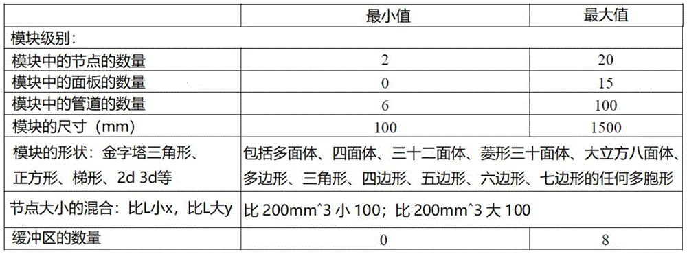
Table 3 includes exemplary characteristics for nodes, connectors, and/or panels.

In layer 1(801), after the reference design is determined, the reference model may be characterized and analyzed by one or more physical simulation and analysis software programs to establish a performance benchmark for the reference model. For example, for a vehicle body structure design, the performance criteria may include the performance of the vehicle body under multiple regulatory loading conditions, such as crash (non-linear transient), NVH (frequency domain), stiffness (linear static), durability (linear static), aerodynamics (CFD), and the like.
Various methods capable of performing simulation tests may be used. Simulation tests may be static or dynamic, deterministic or random, continuous or discrete, and so forth. As previously mentioned, various test models may also be involved (e.g., physical models, empirical models, etc.). Various available CAD (computer aided design) and CAE (computer aided engineering) simulation analysis software programs, such as ANSYS, AutoCAD, Autodesk, SolidWorks, Nastran, Fluent, or pro/Engineer and multiple physics analysis commercially available software, can be used to test and evaluate the performance characteristics of the reference design.
In some embodiments, a customized software program may be provided to interface with existing structural design software and instruct some or all of the analysis programs to run in a batch manner to quickly provide a complete report of all of the characteristics of the design.
In various embodiments, multiple software packages may be launched as multiple simultaneous simulations, which may enable several different aspects of vehicle performance to be measured simultaneously. In various embodiments, the plurality of software packages may be launched sequentially. Multiple copies of the same software may be enabled for testing the same parameters for performance under each set of test conditions. For example, the same vehicle model can be run on the same test track under various weather conditions (hot summer, cold winter, rainy and snowy icy roads) by using the same software. The test scope of the results captured in this test may provide a compressed high-level snapshot of the all-weather performance.
In some embodiments, multiple simulation tests may be run on the same computer. Optionally, multiple simulation tests may be run on multiple computers that may or may not be able to communicate via a network, thereby enabling rapid parallel performance characterization. In some embodiments, hundreds or thousands of tests may be run in parallel, such that a wide set of performance characteristics may be collected in a brief period of time. For example, in the case of all-weather testing, each seasonal variation may be performed on a separate computer. The range of test plans and conditions can be tailored as needed to suit a particular vehicle capability.
In some embodiments, the performance benchmark may include one or more characteristics of the reference model as a result of one or more tests. In some embodiments, the test may be a simulation test that evaluates one or more characteristics of the reference model against a set of criteria. The one or more performance characteristics may include, for example, load carrying capacity, crash and fail-safe, vehicle NVH (noise, vibration and harshness) performance, durability, stiffness, and the like. For example, the simulation may provide analysis results regarding how various components of the vehicle may move or deform during a situation such as a collision. In another example, the analysis may include a time-testing scheme — the performance of the vehicle may be evaluated, for example, by running a test of the vehicle in a manner that starts at zero speed, accelerates to a maximum at a given ramp rate, maneuvers through several gestures, and decelerates back to zero.
In some embodiments, the performance characterization of the reference design may be evaluated and tested under a set of base/minimum requirements. For example, for vehicle body structure design, the basic/minimum requirements may include multiple specification load conditions such as crash (non-linear transient), NVH (frequency domain), stiffness (linear static), durability (linear static), aerodynamics (CFD), and the like. In some embodiments, these basic requirements may be inherited from a reference design. In some embodiments, these base requirements may be modified according to certain rules, or customized from scratch. For example, the requirements may include operating rules set by a governing or licensing authority, federal safety standards, fuel and emissions standards, roadway condition descriptions, environmental descriptions, and the like. These requirements may vary depending on where the vehicle is to be operated (which country jurisdiction) and depending on the purpose of the vehicle (e.g., utility truck, passenger commuter, emergency vehicle, or racing vehicle). In some embodiments, these basic requirements may be defined at the beginning of the design process.
As shown in fig. 8, layer 2(803) may refer to design verification. In some embodiments, the performance results from layer 1(801) may be evaluated and analyzed to verify that the reference design meets a set of requirements. In some cases, the requirements may include basic performance criteria and safety requirements to be met. For example, requirements may specify basic functions and generate behavior and characteristics under stress and fault conditions. In another example, the requirements may include operating rules set by a governing or licensing authority, federal safety standards, fuel and emissions standards, roadway condition descriptions, environmental descriptions, and the like. These requirements may vary depending on where the vehicle is to be operated (e.g., which country jurisdiction) and depending on the purpose of the vehicle (e.g., utility truck, passenger commuter, emergency vehicle, or racing vehicle).
In some embodiments, some requirements may be input by a user. For example, requirements for system level design may be input by a user using a user-friendly interface. An example of a vehicle request interface is shown in FIG. 9. As shown in FIG. 9, the user may be allowed to enter the design requirements using a drop down menu. For example, the user may be provided with the option of entering a registered country, a vehicle class, a collision rating, ground clearance, a synergetics response, a headlight class, an emissions class, and the like. For purposes of illustration, a drop down menu is shown, however, it should be noted that different scales may be provided by the user and various means may be used to allow the user to input or define the requirements. FIG. 9 illustrates an example sub-menu specifying detailed vehicle crash test requirements. The overall crash rating requirement is broken down into individual requirements for each particular crash test.
In some embodiments, the design model may be evaluated through a plurality of simulation tests to determine whether the model meets the requirements. In some embodiments, simulation testing may evaluate the performance of a reference design under various physical test conditions. In some embodiments, one or more sets of test conditions may be predefined and stored in a database. The test conditions may include, for example, ambient temperature and humidity, barometric pressure, wind speed and direction, and solar radiation load. The test conditions may also include measuring the performance of the design model at various times (such as day, night) or different locations (such as equatorial or higher dimensional tests). For example, a set of test conditions may be set to be so extreme as to induce a vehicle fault, and then the performance or failure rate of the design model may be recorded as the results of the test.
In some embodiments, the specification and test results for a design may be represented by a numerical vector. The numerical vector may be multidimensional depending on the particular test. In some embodiments, the design specification may be represented by a numerical vector that may include pass-fail values for certain dimensions. A pass-fail performance vector may be generated by evaluating the results of the simulation test against the requirements, and then a score may be calculated that indicates the level of pass or fail of the requirements. In some embodiments, the various test results may be quantified against corresponding requirements so that the performance test results may be represented in the form of a vector of numerical readings. The vector may include, for example, measures of fuel consumption, hill climbing capability, and temperature for a particular driving cycle. The vector may also incorporate a time series compiled during a normalized trip or driving cycle.
Layer 3
Layer 3(805) may refer to a hierarchy in which a design model is optimized and changed to meet all requirements as previously described. Based on the pass-fail performance vectors challenged and resolved in layer 2(803), the reference model (design) is automatically changed with modifications intended to make its performance meet all requirements. In some embodiments, the present disclosure may enable the variables of the model to be modified at multiple refinement levels (e.g., macro-level, intermediate-level, micro-level, etc.) as previously described. Flexibility in terms of adjusting the parameters of the design model may ensure that the design meets all minimum requirements. Each version of the modified model may be evaluated and the results may be used to guide subsequent modifications. When referring to a single target design optimization, optimization methods or algorithms such as global optimization, local derivative-free optimization, local gradient-based optimization, heuristics, etc. may be used. When a requirement includes conflicting goals or multiple procedures, the design may be modified using the optimization method as previously described.
Layer 4(807) may refer to design optimization at the level that the user prefers driving. In this layer, user preferences may be brought into the optimization process and guide the design direction. In some embodiments, user preferences may be constrained and provided according to design headroom. The design headroom may be identified when a single characterization score from layer 3(803) contains more than the minimum required capacity. This excessive "design capacity" represents overhead space that may be consumed at this level.
At layer 4(807), further optimizations may take into account user preferences. The user may be allowed to select one or more attention attributes, weighting or preference levels, or the like. In some embodiments, a custom software program may be used to direct user input of one or more preferences. In some embodiments, the software program may be configured to provide a list of adjustable attributes to the user for selection and to generate one or more items based on the selected properties and the interrelationships within the set of properties, wherein an item may be a set of contexts that includes at least one selected property and one or more coupled/related properties and a range of tradeoffs or preference levels for the user to adjust within the set of properties. The software may be further configured to display visual representations of the items to the user for them to set preference tiers or tradeoffs, to dynamically update the range of adjustable tradeoffs based on tradeoffs set for other items, and to provide immediate results to the user to help make trade-off decisions.
In some embodiments, the list of tunable properties may include a primary property and a secondary property. In some cases, the primary property may be a property of commonality of the vehicle from the customer's perspective or a property on the product level that is directly related to the customer's desire/experience (such as comfort, maximum speed of the vehicle, etc.). In other cases, the primary property may be a property that is less coupled or correlated with other properties such that fewer computations or iterations may be involved. In some embodiments, a secondary property may refer to a property that may be in the form of engineering design requirements from an engineering perspective, such as size, weight, material, and the like. However, many other means may be used to define the primary and secondary properties. Both the primary and secondary properties may be directly associated with or transformed into various factors as previously described.
In some embodiments, only the primary properties may be displayed to the user. In other embodiments, a list of tunable properties from the primary property or the secondary property, or both, may be provided to the user for selection. In some embodiments, the properties may be determined based on historical priorities or interest levels of the properties displayed to the user. In some cases, the priority or interest level may be derived from historical data indicating areas or properties of interest to the user. In some embodiments, the nature of the display may be determined based on user-specific information retrieved from a database. In some embodiments, the tunable properties provided to the user may be determined based on the current optimization results and the evaluated potential performance.
In some embodiments, an item may be a graph representing the nature of multiple sets of couplings. In some embodiments, these coupled properties may be referred to as attention properties. In some embodiments, the nature of the concern may also be referred to as a concern.
When one or more adjustable properties are coupled to a selected property, one or more items may be automatically displayed to a user for trade-off decisions. In some embodiments, the nature of the coupling or linking may be determined based on the coupling relationship as previously described. For example, the coupling relationship may include different properties affected by the same input variable, an input variable of a property being affected by another property or an output of different properties having conflicting criteria. In some embodiments, the coupling relationship may be predetermined based on various modules (such as the modules described previously) and stored in a database. When the nature of the couplings are determined to be adjustable, they may be displayed to the user for trade-off decisions.
Items may contain any number of concerns that may be grouped together and displayed to a user. The item may contain at least one selected factor and associated unselected factors. The items may contain factors that are all selected factors. In some embodiments, an item may display a set of factors and coupling relationships within the set to a user.
FIG. 10A illustrates an example of a visual representation of concerns and trade-off options for a design for user preferred driving, according to some embodiments. For example, two concerns may be represented by a slider bar that may allow a user to select a level of tradeoff or preference between concerns by selecting the position of the bar. In example 1017, the user may be allowed to use the cursor to move the tradeoff level between the focus factor pattern and the aerodynamics. In some embodiments, when a pair of concerns adjust the weighting hierarchy, the preference/weighting hierarchy of other coupled factors may be automatically calculated and immediately presented to the user.
In another example, the three concerns may be visualized with a triangle having movable objects representing the ratio or level of trade-offs between the three factors. By adjusting the position of the movable object within the confined space, the user can easily provide personal preferences to guide the design process. For example, as shown in fig. 10A, the user may be allowed to move the reference cursor 1021 to determine the tradeoff between cost, speed, and style for the three concerns.
In other embodiments, more than three concerns may be represented by the 3-D visual representation 1015. For example, tetrahedron 1015 may be used. In the 3-D representation example, each vertex may represent a factor of interest and the surfaces of the tetrahedrons may be formed into a constraint space. The user may be allowed to move the reference cursor to determine preferences among the plurality of concerns.
In some embodiments, preferences are provided to users within the constraint space. The scope of the balance hierarchy may be indicated with a visual presentation. For example, the range may be presented with the left and right limits of the slider 1017 or the edges of the triangle 1019.
It should be noted that other shapes (e.g., bars, pyramids, cubes, circles, spheres, etc.) or other forms (e.g., numerical values, images, etc.) of representations may be provided to the user for visualizing the selected concerns and decision tradeoffs. The representation may be a 2-D image (such as slider 1017 and triangle 1019) or a 3-D image (such as tetrahedron 1015).
In the example of triangle 1019, the reference cursor 1021 can be moved in any direction in the two-dimensional plane. The range of movement may be limited by the edges of the triangle. In some embodiments, the available design space may be represented by a highlight region within the triangle space that indicates the possible design headroom. Each vertex may represent a factor of interest (e.g., cost, speed, and style). The position of the cursor may correspond to a ratio of preference or trade-off levels between the three factors. For example, the distance between the preference cursor and each vertex may be proportional to the preference hierarchy. In other cases, the distance may be inversely proportional to the preference level.
In the 3-D representation example 1015, each vertex of a tetrahedron can represent a factor of interest (e.g., aerodynamics, security-RC, comfort-RH, and visibility-DW), and the surface of the tetrahedron can represent a possible design space. In some embodiments, the constraint space or available design space may be graphically depicted as a highlight region or volume within a tetrahedron 1015.
In some embodiments, the user may be provided with a customization of the limited scale in terms of available concerns and associated weighting levels that may be selected. In some cases, the constraint space may refer to selectable factors (tunable factors) that may be determined by an optimization solution. In some cases, the constraint space may refer to a dimensional limit of the hierarchy of tradeoffs within which the user is allowed to set the tradeoffs. For example, based on different analysis results of the current model, relaxed or tightened dimensional limits for the level of tradeoffs for the same set of concerns may be provided, and the user may be allowed to adjust the proportion or level of tradeoffs within the limits. In some embodiments, the availability factors and trade-off metrics may be determined based on design headroom or constraints.
In some embodiments, design headroom may refer to design capacity that may be identified when one or more previous analytical test results (e.g., individual characterization scores obtained from layer 3 (805)) exceed a set of minimum requirements. In some embodiments, the set of optimized solutions (e.g., Pareto edges) may exceed all minimum requirements, in which case the set of optimized solutions in the excess space may be evaluated and provided to the user in the form of a hierarchy of preferences with respect to the relevant factors that may be selected. In some embodiments, the design headroom may vary along the direction of a particular factor (i.e., a focus factor) preferred by the user.
In some embodiments, the concerns presented to the user may not be the same design analysis factors as previously described. In some cases, methods such as Quality Function Deployment (QFD) may be used to translate engineering factors into a form that addresses customer needs. For example, engineering factors (e.g., node location, print time, etc.) may be translated into customer demand related factors (internal comfort, cost, etc.). In some embodiments, customer needs may include tradeoffs between economics, performance characteristics, size and styling, and other derived attributes.
In some embodiments, the user's input may indicate design preferences and may be implemented as requirements/constraints and/or goals for further design optimization. In some embodiments, the user's inputs (e.g., focus and preference/balance hierarchies) may be transformed into engineering requirements/constraints, goals, or test plans for further optimization processes. Methods such as QFD may be used to translate the requirements of the user into engineering requirements. After the user preferences are transformed into engineering analysis factors, analysis of the current model may be performed to evaluate the model against new requirements (derived from user preference input), and then the design may or may not be modified for further optimization based on the analysis results.
In some embodiments, a visual representation of the design may be presented to the user in real-time or near real-time to assist the user in making preference decisions. The visual representation may reflect instantaneous design effects introduced by user-entered tradeoffs or preferences. In some embodiments, the immediate results may be test results that were previously saved in a database such that no calculations or simulation tests are required. In other embodiments, the immediate results may be a calculation based on a new combination of previous test results that may not require lengthy calculation cycles. In other embodiments, the results may be obtained from an optimization process. Based on the particular concerns and weighting levels selected by the user, corresponding changes to the structural design may or may not be visible with the graphical model. In some cases, the user may be able to visualize immediate changes in the appearance of the model, such as the shape, size, number, etc. of the components. In other cases, the user may be allowed to visualize changes in numerical form, such as tables, diagrams, analysis graphs, and the like. In some embodiments, a set of visual representations corresponding to different versions of a design may be presented to a user for comparison and selection. In other embodiments, the user may be allowed to "test drive" the model in a dynamic simulation to evaluate the behavior that has changed, and the preference settings may be locked when the desired performance "feel" is achieved. The user may be provided with various means of virtually testing driving of the vehicle, such as animation, virtual reality, and the like.
10B-C illustrate examples of design optimization on a level that favors driving according to some embodiments. In this example, the design object is a vehicle. The baseline vehicle design may have been evaluated through simulation testing prior to processing on the floor where driving is preferred. For example, a user may find, for current design 1063, that the driver's visibility through the windshield is insufficient by running a vehicle model driving simulation.
A list 1001 of tunable properties may be provided to the user. Any suitable form may be used to display the list of tunable properties, such as a drop down list, a table, a chart, a pictorial representation, and so forth. The user may select one or more properties to adjust. In this example, a "visibility-driver windshield" (visibility-DW) may be selected from the list. When the visibility-DW property is selected, several linked/coupled or affected properties (such as comfort-driver headroom, safety-roof squeeze, aerodynamic-peak ceiling height) may be automatically identified and displayed to the user 1003. Additionally, a graphical representation of the current model with annotated or instantiated properties may be displayed to the user. In some cases, annotated properties may be properties or factors that are highly relevant or associated with the property of interest and are presented to the user for illustrative purposes. In this example, as shown in FIG. 10C, four different vehicle heights 1081 and 1084 are shown to represent the grade glass (visibility-DW) properties. Relaxation of vehicle height limitations may allow a larger or more vertically inclined windshield to provide improved forward road visibility for the driver.
As shown in fig. 10C, the adjustment range for the vehicle height may be affected by the adjustment. The four versions 1061-1064 of the design model correspond to four different heights 1081-1084, with the third model 1063 representing the reference model.
Table 1005 may be a cross-matrix containing all identified properties of interest of the coupling relationships. For example, as shown in table 1005, the coupling relationship may be identified and represented by six pairs: t1, T2, T3, T4, T5 and T6.
Further, each pair of attention properties may be displayed with a user-selectable slider control 1007, which the user may or may not select an adjustment slider. The user may be prompted to determine a preference level or tradeoff between a pair of properties by adjusting the position of the slider.
As previously mentioned, the coupling relationship may be expressed in many other ways. For example, the same list of interesting properties may be shown in the form of tetrahedron 1094 in FIG. 10A. This can be shown on the screen as real-time updates as the slider is moved. Each of the four properties can be mapped to one vertex of a tetrahedron (visibility-DW 1095, comfort-DH 1096, security-RC 1097, and aerodynamic-RH 1098). Each edge may represent a permutation of pairs of two properties, for a total of six edges. Each swap slider T1, T2, T3, T4, T5, and T6 represents a point along one of the six edges. The slider set percentages for each pair may be expressed as points along the edge.
In some cases, the graphical representation of the vehicle model corresponds to a trade-off selection that may be displayed to the user 1011 instantaneously. Users may be allowed to immediately visualize direct and indirect changes to the design model as a result of their expressed trade-off preferences.
In some embodiments, a visual representation of the concerns and trade-off options for a design that a user prefers to drive and a visual representation of the design may be displayed to the user on a device. FIG. 10D illustrates an example of an apparatus providing a graphical user interface and user interaction in accordance with an embodiment of the present disclosure. In some embodiments, the device may be a computing device. The apparatus may include a display 1023 to display a visual representation of user input preferences. The display screen may or may not include touch sensing input capabilities. The apparatus may include a processor and/or a memory. The memory may include a non-transitory computer-readable medium including code, logic, or instructions for performing one or more steps, such as design steps or calculations. The processor may be configured to perform steps in accordance with the non-transitory computer-readable medium. The device may be a desktop computer, a battery, a smart phone, a tablet, a laptop, a server, or any other type of computing device. The apparatus may communicate with a 3-D printer. The device may or may not be a network device. In some embodiments, the device may be capable of connecting to a network, such as a Local Area Network (LAN), a Wide Area Network (WAN), such as the internet, a telecommunications network, a data network, or any other type of network.
In some embodiments, the user may be allowed to move the preference cursor via the user interaction device 1019. Examples of such user interaction devices may include a keyboard, buttons, a mouse, a touch screen, a touch pad, a joystick, a trackball, a camera, a microphone, a motion sensor, a thermal sensor, an inertial sensor, or any other type of user interaction device.
Referring back to fig. 8, layer 5(809) may refer to a hierarchy of machine learning optimizations. At this level, design optimization may involve data from actual products and/or experiments through physical models. In some embodiments, a database of designs, manufacturing experiences, design experiences, manufacturing performance, product performance, and the like may be compiled and regularly updated. For example, the data stored in the database may include feedback generated after delivery of the component or product, so it captures the final outcome from the process. The outcome may be, for example, either satisfactory or unsatisfactory. For example, the database may include data collected from the entire life cycle of the product. The data set may include product manufacturing (from mining/preparation raw materials), design processing, manufacturing, delivery, field use, and final recovery. In another example, historical data collected from the performance of similar products under various realistic conditions may be recorded and analyzed. In some embodiments, for the vehicle design database, the data may further contain information related to the customer, such as preferences, habits, driving behavior, and the like. Techniques such as machine learning, neural network analysis techniques, and the like may be used to extract knowledge and patterns from the database.
In some embodiments, information extracted from the database of physical data may be used to guide further modifications and improvements to the design model. For example, information related to customer behavior may be decomposed into design optimization processes to achieve a personalized final design product. Information learned from actual physical products can improve design optimization and deliver products that are difficult to achieve based on only conventional mathematical models and numerical simulations.
FIG. 11 shows a diagram of the data flow through an exemplary design optimization cycle. In some embodiments, one or more optimization cycles may be involved in multiple layers in the present disclosure. Various 3-D printed structure based objects as described above may be optimized by the presented method. The following embodiments are related using the vehicle structure as an example; however, the optimization method may be applied to any subsystem of a vehicle, such as a tire or engine of a vehicle, or may be used in the design of other non-motor vehicle structures.
In some embodiments, the design optimization cycle may begin with a parameterized CAD (computer aided design) model 1101 of the vehicle. The initial vehicle model 1101 may contain a complete parametric description of the vehicle, such as structure, tires, engine, doors, transmission, cooling system, etc. The initial vehicle model 1101 may include a three-dimensional description of each component and how they are attached to each other. The initial vehicle model 1101 may also contain material properties for various glass, metal, rubber, and plastic components. As previously mentioned, a database may be used to store a number of design models that may be used as an initial design.
The test plan and conditions 1111 may be a predefined set of tests specified for the vehicle. In some embodiments, a test plan may include various simulation modules implemented as sets of computer-coded instructions, and test conditions may include sets of parameters to be applied to the corresponding test plan for various testing purposes. The simulation test unit 1103 may acquire a vehicle model 1101 and a test plan and conditions 1111, and perform a simulation test with analysis software. For example, simulator 1103 may perform a set of simulated stressful manipulations on the model that may cause extreme behavior, and measurements of performance may be taken at appropriate times.
The test plan and conditions 1111 may describe the physical test process of how the model is to be evaluated under a number of predefined test scenarios. For example, the test conditions may specify, for example, ambient temperature and humidity, barometric pressure, wind speed and direction, and solar radiation load (for day, night, equatorial, or higher dimensional tests). In another example, the test conditions may include multiple protocol loading conditions such as crash (non-linear transient), NVH (frequency domain), stiffness (linear static), durability (linear static), aerodynamics (CFD), and the like. Some test conditions may be so extreme as to deliberately induce a vehicle fault. Finding and measuring where or how faults occur can be a key feature of the test. For example, the simulation may provide an indication of how various components of the vehicle may move or deform during a situation such as a collision. In another example, the analysis may include a time-testing scheme — the performance of the vehicle may be evaluated, for example, by running a test of the vehicle, starting at zero speed, accelerating to a maximum at a given ramp rate, maneuvering through a list of predetermined waypoints, speeds, turns, or obstacles, and decelerating back to zero.
The simulation test unit 1103 may include a set of software packages that may be launched as a plurality of simulations. The set of software packages may or may not be run simultaneously. In some embodiments, the software package may be instructed to perform tests according to each of its own plans and conditions specified by test plans and conditions 1111. This plurality of simulation tests may enable several different aspects of vehicle performance to be measured. Various simulation analysis software can be used for analysis, such as ANSYS, AutoCAD, Autodesk, SolidWorks, Nastran, Fluent, or pro/Engineer can be used for various design analyses.
In some embodiments, multiple software packages may be launched as multiple simultaneous simulations, which may allow several different aspects of vehicle performance to be measured simultaneously. In other embodiments, the plurality of software packages may be launched sequentially. Multiple copies of the same software may be enabled for testing the same parameters for performance under each set of test conditions. For example, the same vehicle model can be run on the same test track under various weather conditions (hot summer, cold winter, rainy and snowy icy roads) by using the same software. The test scope of the results captured in this test may provide a compressed high-level snapshot of the all-weather performance.
In some embodiments, multiple simulation tests may be run on the same computer. Optionally, multiple simulation tests may be run on multiple computers that may or may not be able to communicate via a network, thereby enabling rapid parallel performance characterization. In some embodiments, hundreds or thousands of tests may be run in parallel, such that a wide set of performance characteristics may be collected in a brief period of time. For example, in the case of all-weather testing, each seasonal variation may be performed on a separate computer. The range of test plans and conditions can be tailored as needed to suit a particular vehicle capability.
FIG. 12 shows a rendering 1200 of an exemplary output of one cycle of simulation test software. This is a structural analysis of linear node positions and pipe topology. The illustrated architecture is a node-based vehicle frame with sensitivity analysis of node location and topology. Some parts of the structure may be more sensitive to node location and topology with respect to the current optimization objective. In this example, the left side 1201 of the structure (as seen in FIG. 12) is more sensitive to node location than the right side 1203 of the structure. The simulation test results may drive one or more changes to the left side of the structure.
Referring back to FIG. 11, as the testing phase proceeds, measurements from the various tests may be compiled and recorded as performance test results 1105 in the form of a vector of numerical readings. The vector may include measures such as fuel consumption, hill climbing capability, and temperature under stress. The vector may also incorporate a time series compiled during a normalized trip or driving cycle.
After the simulated tests are completed, optimality evaluation unit 1115 may evaluate compiled performance test results 1105. The optimality assessment unit 1115 may measure the acceptability of the performance of the model using pre-selected target states expressed as targets and constraints 1113. The distance from the current performance level of the model to the target performance level may be quantitatively measured. The direction of this vector in the performance space can be used to guide further optimization by changing the settings of the increment step size, stepping direction, weighting factors, etc. for subsequent optimization iterations.
Fig. 13 shows a graph of exemplary performance test results 1105 evaluated by the optimality evaluation unit 1115. In this example, the graph illustrates two of the dimensions of performance test result vector 1105, which form two axes, "test score A" and "test score B". The two test scores may represent any two factors, such as fuel economy and hill climbing capability.
The two axes are oriented with the least desirable quadrant in the lower left and the most desirable quadrant in the upper right. In part a of fig. 13, a point 1350 may represent the estimated coordinates of the target state. There may be some excess space between the corner and the target that represents over-designed or over-capable product conditions.
The test results from the performance test result vector of the single simulation test are represented as points 1341. Constraint line 1348 may represent the limit-bounds imposed by other dimensions of the test result vector that are not representable on the graph. The area to the right of the constraint line 1348 may violate the functional needs of the product, so there is no acceptable solution in this area. The graph in section a shows that the target 1350 is outside of the constrained space. This indicates that the target point 1350 is not achievable by any simple exchange between the test score a and the test score B. This case may correspond to a typical product performance space in which the target direction is explicitly set, but for which no solution is directly visible or achievable.
In this case, the points 1351 and 1352 are displayed as the most suitable candidates as shown in section B. Both points 1351 and 1352 satisfy the constraint boundary line 1348 and both are proximate to the target point 1350. Subsequent steps illustrate how the software explores the space to find the optimal satisfactory solution.
In another case, when a test indicates that the model has achieved or exceeded a performance goal, the test results may be satisfactory in this scoring dimension. In this case, further optimization in the current change direction may not result in a valid value. The iterative process is then either redirected or terminated by the optimality assessment unit 115.
In yet another case, a design violation may have occurred when testing indicates that one or more constraint surfaces have been exceeded. In this case, optimality assessment unit 1115 may instruct the optimization process to "fall back" to the previous higher scoring design iteration. This removes the effect of recent design changes. The finding of the direction of deterioration is an indication that further incremental probing in this parametric direction will not be productive. Similarly, when the constraining surface is found to block incremental improvement, this is an indication that the optimal value has been reached.
Referring to fig. 11, in the event that the optimality evaluation unit 1115 finds that the current model has achieved the performance goal, the design process may end, and the current model may be output as the optimal vehicle model 1117. In the case where the optimality evaluation unit 1115 indicates a change requirement, the design change unit 1107 may make an incremental change to the initial vehicle model 1101 and generate a changed vehicle model 1109.
In some embodiments, changes may be made to one or more design parameters in the original model 1101. The parameters may be selected from a subset of interest of all vehicle parameters. In some cases, the parameters may be selected manually in the case of guided optimization. In other embodiments, the parameters may be automatically selected in the case of an open or full vehicle global optimization. In some embodiments, the parameters may be varied at various design improvement levels as previously described.
After the model 1109 has been changed, it may replace the initial vehicle model 1101 as a new updated vehicle reference design.
In some embodiments, simulation test unit 1103, optimality evaluation unit 1115, and design change unit 1107 may be implemented with one or more custom software programs. The one or more software programs may be configured to interface with one or more simulation and analysis software programs. In some embodiments, one or more databases storing data involved in the design process as described elsewhere (e.g., initial vehicle model 1101, test plans and conditions 1111, goals and constraints 1113, performance test results 1105, altered vehicle model 1109, optimal vehicle model 1117, etc.) may be included.
In some embodiments, the optimization direction may be tracked by visualizing the iteration results. By comparing the optimized path with the target, a further optimization direction can be decided. The graph in section C of fig. 13 shows performance test result scores from four consecutive iterations 1341, 1342, 1343, and 1344. Each result is generated by a set of simulation tests run on the iteratively changed model. In some embodiments, the changes may be applied to design changes. The pattern of the optimized paths may be evident in the continuous change for each performance test score 1341, 1342, 1343, and 1344.
In another aspect, the present disclosure provides a method and system for designing an object based on a 3-D printed structure, wherein the design process dynamically incorporates user preferences and physical data to enable an efficient personalized design.
In some embodiments, the requirements of the design may be incorporated into a hierarchical design process on different layers, and thus many variations of design models, test results, analysis may be produced. In some embodiments, various data involved during the design process may be stored in one or more databases.
FIG. 14 illustrates an example of data that may be contained in a database, according to some embodiments. It should be noted that the vehicle design is used herein for illustrative purposes, and any other design product related data may be stored in the database based on the particular design.
The database(s) may be configured to store data (e.g., sentence structures, sentence elements, words and images for each sentence element, etc.). Additionally, in some embodiments, the database(s) may also be implemented as a computer system having storage. In one aspect, a component of an optimization system can use a database(s) to perform one or more operations consistent with the disclosed embodiments. One of ordinary skill in the art will recognize that the disclosed embodiments are not limited to the configuration and/or arrangement of the database(s).
In some embodiments, database 1410 may contain data related to designed models and actual products. Databases (e.g., libraries, vehicle design repositories) may be created and used during the design phase. The database may be stored on one or more non-volatile memories of the computing device. The database may be stored on the user/designer's local computing device. The database may also be stored on a cloud infrastructure that may be accessed by multiple users at various locations. Nodes and connectors, chassis subassemblies, chassis substructures, chassis modules, and/or chassis that have been designed and manufactured for individual vehicles may be recorded in a database. The various characteristics and corresponding identifiers for each part may be recorded in a database. Such a database may be used as a template when a user begins designing and manufacturing another vehicle. Such a database may also be used as a reference for maintenance and/or upgrades to previously manufactured vehicles.
In some embodiments, database 1410 may contain data related to a model of a design. In some embodiments, the model may be a physical model such that the relevant data may include feedback from experiments, system tests, vehicle field tests using the physical model. In this case, any suitable means (such as sensory immersion, monitors, and human experiences) may be used to obtain the feedback data. In other embodiments, the model may be a mathematical model that allows data to be correlated to a numerical simulation, test, analysis, parameterized model, or design description of one or more vehicles.
For example, database 1410 may include a library of reference vehicle designs, environmental and test specifications, product requirements, customer preferences, dynamic models, micro-factory and manufacturing specifications, material and component specifications, vehicle field operation logs, and end-of-life logs.
During the hierarchical vehicle design and optimization process, database 1410 may be coupled to five-layer design process 1411. For example, the database may interactively read data associated with the design process, such as predefined requirements, user input preferences, test plans, performance optimization data, manufacturing optimization data, and life cycle optimization data. In some embodiments, requirements and goals regarding the basic operation of the vehicle that may be tracked through the database may be altered and improved. As previously described, the requirements may be inherited from the reference vehicle and modified from the property list, or customized from the scratch. The requirements may include, for example, operating rules set by a governing or licensing authority, federal safety standards, fuel and emissions standards, roadway condition descriptions, environmental descriptions, and the like. These requirements may vary depending on where the vehicle is to be operated (which country jurisdiction) and depending on the purpose of the vehicle (e.g., utility truck, passenger commuter, emergency vehicle, or racing vehicle).
Some requirements may be defined once at the beginning of the vehicle design and remain unchanged for the life of the vehicle. These requirements may affect the basic vehicle definition profile or basic definition of the vehicle.
Other requirements may be defined in the middle of the design process, such as user preferences. These may include vehicle type and overall size, and establish some basic tradeoffs between factors that address customer needs, such as economy, performance characteristics, size and styling, and other derived attributes as described elsewhere.
At the same time, the database may also record data generated during the design process, such as measurements of various aspects of vehicle-model performance and model parameters at all or some of the steps of the design process.
In some embodiments, database 1410 also contains data related to actual products 1413. These external sources 1413 can provide real world feedback regarding the physical effort. Data from these sources 1413 can include unexpected variations or tolerances during manufacturing (e.g., GD & T), previously unknown physical phenomena, and unexpected optimization results. For example, the data stored in the database may include feedback generated after delivery of the component or product, so it captures the final outcome of the process. The results may be either satisfactory or unsatisfactory. For example, the database may include data collected from the entire life cycle of the product. The data set may include product manufacturing (starting with mining/preparation of raw materials), their design process, their manufacture, delivery, field use, and ultimate recovery. In another example, historical data collected from the performance of similar products under various realistic conditions may be recorded and analyzed. In some embodiments, for a vehicle design database, the data may further contain information related to the customer, such as preferences, habits, environmental and road conditions, driving behavior, and the like.
In a 3-D printed node based manufacturing system, data may be captured and incorporated into database 1410 so that information may be considered during the design of subsequent products or during the revision of existing products. In some embodiments, data feedback may be generated and displayed in real-time.
FIG. 15 illustrates an example of data that may be obtained from a manufacturing process and other processes, according to an embodiment. As shown in fig. 15, the data may be obtained from various fields, such as materials used (e.g., powders, material labels, processing parameters, etc.), printers (e.g., component test data, machine print data, part labels, etc.), assembly machines (e.g., test data, assembly labels, etc.), vehicle data (vehicle build tracking, node tracking, etc.), smart nodes (e.g., built-in sensors, usage data, etc.). In some embodiments, data from the physical product may be fed back to the design process in a short period of time so that the design may be improved before it is delivered to the customer. The data may be stored in database 1500.
For example, data may be captured by sensors incorporated into nodes or junctions (smart nodes) for detecting forces, utilizing activities and states, pressure, temperature, and/or any other parameters. In some embodiments, the sensors may be integrated into the joint via a 3-D printing process. The sensors may detect major failures of the joints or pipes. The integrated sensors may determine whether a junction or other component of the vehicle is suitable for service following a collision. The data captured from the sensors may provide real-world performance results of the design in a timely manner such that further improvements to the design may be made possible.
In some embodiments, the present disclosure may allow individuals to design their desired structure. In this case, the database may include user-specific data. The database may include an individual's order history, shipping preferences (e.g., assembled structure, semi-assembled or fully customized vehicles), an individual's driving habits, reports on driving experiences, safety, etc.
The present disclosure may also enable adjustments to be made to parts or part quality related to performance in the field. For example, the database may contain triggers based on redesign in the field of warranty claims or customer complaints. The system may be updated based on any number of performance criteria and the design will be adjusted to address performance, durability, alignment, wear, or other issues.
Fig. 16 illustrates a schematic block diagram of an exemplary design optimization system 1600 in accordance with an embodiment of the present disclosure. The design optimization system may be configured to perform the design and optimization operations as described elsewhere herein. Design optimization system 1600 may include devices including one or more processors 1601, memory 1603, graphical user interfaces 1605, and user interaction devices. The memory may include a non-transitory computer-readable medium including code, logic, or instructions for performing one or more steps, such as design steps or calculations. The memory may include one or more databases as shown in fig. 14. The processor may be configured to perform steps in accordance with the non-transitory computer-readable medium. The graphical user interface and user interaction means may allow user input preferences and requirements for the design as described in fig. 10D. The device may be a desktop computer, battery, smart phone, tablet, laptop, server, or other type of computing device. It should be understood that the term design optimization herein may refer to customization or personalization of a design, and may be used interchangeably throughout this description.
In some embodiments, the apparatus may be a cloud-based processing cluster implemented on a server configured to operate as a head end apparatus, wherein the head end apparatus is configured to provide a graphical user interface to a user. The server may include known computing components, such as one or more processors, one or more memory devices that store software instructions and data for execution by the processor(s). The server may have one or more processors and at least one memory for storing program instructions. The processor(s) may be a single microprocessor or multiple microprocessors, Field Programmable Gate Arrays (FPGAs), or Digital Signal Processors (DSPs) capable of executing a particular set of instructions. The computer readable instructions may be stored on a tangible, non-transitory computer readable medium, such as a flexible disk, a hard disk, a CD-ROM (compact disk-read only memory), and MO (magneto-optical), a DVD-ROM (digital versatile disk-read only memory), a DVD RAM (digital versatile disk-random access memory), or a semiconductor memory. Alternatively, the methods disclosed herein may be implemented in hardware components or a combination of hardware and software, such as, for example, an ASIC, a special purpose computer, or a general purpose computer.
As previously described, the server may be a server in a data network (such as a cloud computing network). A server may be a computer programmed to send data, accept requests, distribute work with other computing devices and/or user interfaces. Additionally, the server may include a web server, an enterprise server, or any other type of computer server.
17A-B illustrate exemplary modifications to elements of a vehicle front end structure to meet ground clearance criteria. The modification may be determined by an integrator (such as, for example, integrator 219 of fig. 2). Fig. 17A illustrates a design model 1701 illustrating a vehicle body front end structure. The design model 1701 may be, for example, an initial design model or may be a design model that has been determined after multiple iterations of a design process such as the multifactor integration described above. Impact beam 1703 and underbody frame beam 1705 are joined by CAD optimized node 1707, which CAD optimized node 1707 is designed to transfer impact loads to the underbody structure. The design model 1701 has a bumper height 1709 based on government mandated requirements. The design model 1701 also has a ground clearance 1711. In this example, the ground clearance 1711 does not meet the minimum ground clearance criteria. Integrators, such as integrator 219, may modify the design model by, for example, raising the ground clearance. The information of the elevated ground clearance may be sent to a CAD analysis component to analyze the updated design model and provide the analysis to the integrator. In this example, the analysis provided by the CAD analysis component may include a modified node structure as shown in FIG. 17B.
FIG. 17B illustrates an updated design model 1713 based on the analysis provided by the CAD analysis component. Specifically, the ground clearance of the vehicle has been increased as shown by the increased ground clearance 1715. This reduces the difference in height between the impact beam 1703 and the frame beam 1705. The node design has been analyzed and automatically recalculated to CAD-modified node 1717. Thus, for example, the analysis provided by the CAD analysis component (i.e., CAD-modified nodes) can be integrated by the integrator into the updated design model 1713, although not shown in the figures, the integrator can also receive updated analyses from a plurality of other analysis components, such as updated costs, updated weights, updated collision simulation results, updated aerodynamics, and the like. The updated analyses from the various multiple analysis components may all be integrated by the integrator to determine an updated design model 1713. If all of the vehicle criteria are met, the iteration may end and 3-D printing instructions for printing one or more parts (such as CAD modified node 1717) may be generated. Some parts may be, for example, COTS parts that may be ordered through a supply system.
The system may continue to iteratively optimize the design even when the updated design model 1713 satisfies all of the vehicle criteria. In various embodiments, some criteria may be weighted when improvement is more desirable. For example, once all vehicle criteria are met, the system may attempt to improve the drag coefficient before attempting to improve the overall vehicle cost.
FIG. 18 illustrates an exemplary multi-factor integrated design process. FIG. 18 illustrates some exemplary user inputs that may form the basis of product plan 1801. The various elements of product plan 1801 may be user selectable, for example, by sliders, selectors, etc. that may be presented to the user in a graphical user interface on a computer display. For example, the target customer may be selected as private or commercial. Demographic information may also be entered. One or more markets may be selected, such as north america, europe, and the like. The product volume may be selected, for example, with a slider ranging from a low volume to a high volume. The target manufacturer retail price (MSRP) may be entered as a single value or range of values. Preference characteristics may be selected such as highest speed (e.g., slow to fast), on/off highway characteristics, and the like. The degree of autonomy may be selected. Manufacturing characteristics may be selected, for example, the amount of 3-D printing that may be used to print a part of a vehicle versus the amount of COTS components that may be used.
The system may generate a product description 1803 based on the product plan 1801 input. For example, product description 1803 may include elements such as: brand identity, product image, primary functionality, number of occupants, legal requirements, cost, emissions, top speed, acceleration, handling, off-highway capability, cargo carrying capability, NVH, GVW, production volume, manufacturing process, etc.
The product description 1803 may form the basis of a vehicle architecture design analysis 1805. That is, the particular vehicle criteria may be determined based on the product description 1803. The criteria may include, for example, input criteria such as: a ground clearance; the requirement of the center of gravity; aerodynamic requirements; the depth of the vehicle body bottom structure; across height/width; ease of ingress and egress; eye point height above ground; forward looking; head space requirements; a total height limit; designing-proportion; and the degree of autonomy (driver orientation). Hard point output and deliverable criteria may include: heel end point X and Z positions; ball of the foot X and Z positions; h point X and Z position (SgRP); a relief angle; an effective overhead spatial point; upward viewing angle; downward viewing angle; an eye ellipse position; a head contour position; tibial CL location; thigh CL location; and V1 and V2 eyepoints. The affected/facilitated system location criteria may include: a driver's seat; a steering wheel; a gearbox; an instrument panel; a base plate; front door aperture (a-B flange); an instrument cluster shelter; the height of the vehicle roof; a head position; the height of the top cover; a pillar shield; reach area (all controls and switches); a mirror; the rear plane of the collision space for FMVSS 208; a seat tracking travel envelope; a rear rider setting; the total height; and knee stops. Other input criteria may include: load size/volume; cargo carrying weight; a desired elevation height; and protection requirements (from elements, theft, impact). Other hard point output/deliverable criteria may include: trunk/base size; vehicle interior height and width dimensions; the height of the cargo bed floor; raising the height; a loading port (a-B flange). Other affected/facilitated system location criteria may include: a seat; vehicle body structures (floor, underbody frame, enclosure); axle position; a tire profile; the overall size; a collision load; testing the durability; and the selection of the suspension.
Thus, there may be many specific criteria that may be based on user input in the form of product plan 1801.
FIG. 19 is a flow chart illustrating an exemplary integrated design process. The processing may be performed, for example, by a processor executing computer-executable program instructions. In various embodiments, an integrator (such as integrator 219) may perform the process shown in FIG. 19. The integrator may send (1801) information based on the design model of the vehicle to a plurality of analysis components. For example, the integrator may use the initial design model, may determine specific information about the design model related to the first analytical component (such as the air hole dynamics component), and may send this information to the first analytical component. Likewise, the integrator can determine relevant information and send the relevant information to other analysis components. The information sent to each analysis component enables the analysis component to perform analysis of the design model based on the analysis factors of the analysis component.
The integrator may receive (1802) analyzed information from each analysis component. The integrator may update (1803) the design model based on the analyzed information. The integrator may determine (1804) whether the updated design model satisfies criteria of the vehicle, such as the various criteria discussed above. The integrator may determine (1805) printing instructions for causing the 3-D printer to additively manufacture one or more structures of the vehicle based on the updated design model and to print the one or more structures based on the updated design model (if the updated design model satisfies the criteria). On the other hand, if the updated design model does not satisfy the criteria, the integrator can send information based on the updated design model to the analysis component such that the analysis component can analyze the information based on the updated design model.
The preceding description is provided to enable any person skilled in the art to practice the various aspects described herein. Various modifications to these exemplary embodiments, as presented throughout this disclosure, will be readily apparent to those skilled in the art. Thus, the claims are not intended to be limited to the exemplary embodiments presented throughout this disclosure, but are to be accorded the full scope consistent with the language claims. All structural and functional equivalents to the elements of the exemplary embodiments described throughout this disclosure that are known or later come to be known to those of ordinary skill in the art are intended to be encompassed by the claims. Moreover, nothing disclosed herein is intended to be dedicated to the public regardless of whether such disclosure is explicitly recited in the claims. No claim element is to be construed in accordance with 35u.s.c. § 112(f) or similar laws in the applicable jurisdiction, unless the element is explicitly recited by the use of the phrase "means for … …" or, in the case of a method claim, by the use of the phrase "step for … …".
Claims (36)
Priority Applications (1)
| Application Number | Priority Date | Filing Date | Title |
|---|---|---|---|
| CN202110307810.1A CN113001987B (en) | 2016-05-24 | 2017-05-24 | System and method for additive manufacturing of transport structures |
Applications Claiming Priority (3)
| Application Number | Priority Date | Filing Date | Title |
|---|---|---|---|
| US201662340930P | 2016-05-24 | 2016-05-24 | |
| US62/340,930 | 2016-05-24 | ||
| PCT/US2017/034348 WO2017205555A1 (en) | 2016-05-24 | 2017-05-24 | Systems and methods for additive manufacturing of transport structures |
Related Child Applications (1)
| Application Number | Title | Priority Date | Filing Date |
|---|---|---|---|
| CN202110307810.1A Division CN113001987B (en) | 2016-05-24 | 2017-05-24 | System and method for additive manufacturing of transport structures |
Publications (2)
| Publication Number | Publication Date |
|---|---|
| CN109478053A CN109478053A (en) | 2019-03-15 |
| CN109478053B true CN109478053B (en) | 2021-04-02 |
Family
ID=60412948
Family Applications (2)
| Application Number | Title | Priority Date | Filing Date |
|---|---|---|---|
| CN202110307810.1A Active CN113001987B (en) | 2016-05-24 | 2017-05-24 | System and method for additive manufacturing of transport structures |
| CN201780044765.7A Active CN109478053B (en) | 2016-05-24 | 2017-05-24 | System and method for additive manufacturing of transport structures |
Family Applications Before (1)
| Application Number | Title | Priority Date | Filing Date |
|---|---|---|---|
| CN202110307810.1A Active CN113001987B (en) | 2016-05-24 | 2017-05-24 | System and method for additive manufacturing of transport structures |
Country Status (12)
| Country | Link |
|---|---|
| US (1) | US10303159B2 (en) |
| EP (2) | EP3961468A1 (en) |
| JP (3) | JP7107852B2 (en) |
| KR (2) | KR102445973B1 (en) |
| CN (2) | CN113001987B (en) |
| AU (1) | AU2017270086B2 (en) |
| CA (1) | CA3025470A1 (en) |
| ES (1) | ES2909578T3 (en) |
| HU (1) | HUE058865T2 (en) |
| SG (1) | SG11201810504TA (en) |
| SI (1) | SI3463819T1 (en) |
| WO (1) | WO2017205555A1 (en) |
Cited By (1)
| Publication number | Priority date | Publication date | Assignee | Title |
|---|---|---|---|---|
| US11494820B2 (en) | 2020-12-14 | 2022-11-08 | Toyota Motor North America, Inc. | Augmented reality automotive accessory customer collaborative design and manufacturing through 3D printing |
Families Citing this family (148)
| Publication number | Priority date | Publication date | Assignee | Title |
|---|---|---|---|---|
| US10181160B1 (en) | 2014-04-25 | 2019-01-15 | State Farm Mutual Automobile Insurance Company | Systems and methods for assigning damage caused by an insurance-related event |
| EP3145798B1 (en) | 2014-05-16 | 2019-11-13 | Divergent Technologies, Inc. | Modular formed nodes for vehicle chassis and their methods of use |
| WO2016003982A1 (en) | 2014-07-02 | 2016-01-07 | Divergent Technologies, Inc. | Systems and methods for fabricating joint members |
| KR20190006593A (en) | 2016-06-09 | 2019-01-18 | 디버전트 테크놀로지스, 인크. | Systems and methods for arc and node design and fabrication |
| US11062058B2 (en) * | 2016-08-11 | 2021-07-13 | Autodesk, Inc. | Usage feedback loop for iterative design synthesis |
| US10759090B2 (en) | 2017-02-10 | 2020-09-01 | Divergent Technologies, Inc. | Methods for producing panels using 3D-printed tooling shells |
| US11155005B2 (en) | 2017-02-10 | 2021-10-26 | Divergent Technologies, Inc. | 3D-printed tooling and methods for producing same |
| US10737478B2 (en) * | 2017-02-24 | 2020-08-11 | Ford Global Technologies, Llc | Manufacture of vibration damping structures |
| EP3379434B1 (en) * | 2017-03-22 | 2022-09-28 | Tata Consultancy Services Limited | A system and method for design of additively manufactured products |
| US12251884B2 (en) | 2017-04-28 | 2025-03-18 | Divergent Technologies, Inc. | Support structures in additive manufacturing |
| US10898968B2 (en) | 2017-04-28 | 2021-01-26 | Divergent Technologies, Inc. | Scatter reduction in additive manufacturing |
| EP3621809A4 (en) * | 2017-05-11 | 2021-01-20 | Seurat Technologies, Inc. | PATTERNED SEMICONDUCTOR LIGHT GUIDANCE FOR ADDITIVE MANUFACTURING OPTIMIZATION |
| US10703419B2 (en) | 2017-05-19 | 2020-07-07 | Divergent Technologies, Inc. | Apparatus and methods for joining panels |
| US11358337B2 (en) | 2017-05-24 | 2022-06-14 | Divergent Technologies, Inc. | Robotic assembly of transport structures using on-site additive manufacturing |
| US11123973B2 (en) | 2017-06-07 | 2021-09-21 | Divergent Technologies, Inc. | Interconnected deflectable panel and node |
| US10733332B2 (en) * | 2017-06-08 | 2020-08-04 | Bigwood Technology, Inc. | Systems for solving general and user preference-based constrained multi-objective optimization problems |
| US10919230B2 (en) | 2017-06-09 | 2021-02-16 | Divergent Technologies, Inc. | Node with co-printed interconnect and methods for producing same |
| US10781846B2 (en) | 2017-06-19 | 2020-09-22 | Divergent Technologies, Inc. | 3-D-printed components including fasteners and methods for producing same |
| WO2018234331A1 (en) * | 2017-06-20 | 2018-12-27 | Carl Zeiss Ag | METHOD AND DEVICE FOR ADDITIVE MANUFACTURE |
| US10994876B2 (en) | 2017-06-30 | 2021-05-04 | Divergent Technologies, Inc. | Automated wrapping of components in transport structures |
| US11022375B2 (en) | 2017-07-06 | 2021-06-01 | Divergent Technologies, Inc. | Apparatus and methods for additively manufacturing microtube heat exchangers |
| US10895315B2 (en) | 2017-07-07 | 2021-01-19 | Divergent Technologies, Inc. | Systems and methods for implementing node to node connections in mechanized assemblies |
| US10940609B2 (en) | 2017-07-25 | 2021-03-09 | Divergent Technologies, Inc. | Methods and apparatus for additively manufactured endoskeleton-based transport structures |
| US10751800B2 (en) | 2017-07-25 | 2020-08-25 | Divergent Technologies, Inc. | Methods and apparatus for additively manufactured exoskeleton-based transport structures |
| US10605285B2 (en) | 2017-08-08 | 2020-03-31 | Divergent Technologies, Inc. | Systems and methods for joining node and tube structures |
| US10357959B2 (en) | 2017-08-15 | 2019-07-23 | Divergent Technologies, Inc. | Methods and apparatus for additively manufactured identification features |
| US11306751B2 (en) | 2017-08-31 | 2022-04-19 | Divergent Technologies, Inc. | Apparatus and methods for connecting tubes in transport structures |
| US10960611B2 (en) | 2017-09-06 | 2021-03-30 | Divergent Technologies, Inc. | Methods and apparatuses for universal interface between parts in transport structures |
| US11292058B2 (en) | 2017-09-12 | 2022-04-05 | Divergent Technologies, Inc. | Apparatus and methods for optimization of powder removal features in additively manufactured components |
| US10668816B2 (en) | 2017-10-11 | 2020-06-02 | Divergent Technologies, Inc. | Solar extended range electric vehicle with panel deployment and emitter tracking |
| US10814564B2 (en) | 2017-10-11 | 2020-10-27 | Divergent Technologies, Inc. | Composite material inlay in additively manufactured structures |
| US11786971B2 (en) | 2017-11-10 | 2023-10-17 | Divergent Technologies, Inc. | Structures and methods for high volume production of complex structures using interface nodes |
| US10926599B2 (en) | 2017-12-01 | 2021-02-23 | Divergent Technologies, Inc. | Suspension systems using hydraulic dampers |
| US11110514B2 (en) | 2017-12-14 | 2021-09-07 | Divergent Technologies, Inc. | Apparatus and methods for connecting nodes to tubes in transport structures |
| US11085473B2 (en) | 2017-12-22 | 2021-08-10 | Divergent Technologies, Inc. | Methods and apparatus for forming node to panel joints |
| US11534828B2 (en) | 2017-12-27 | 2022-12-27 | Divergent Technologies, Inc. | Assembling structures comprising 3D printed components and standardized components utilizing adhesive circuits |
| US11420262B2 (en) | 2018-01-31 | 2022-08-23 | Divergent Technologies, Inc. | Systems and methods for co-casting of additively manufactured interface nodes |
| US10751934B2 (en) | 2018-02-01 | 2020-08-25 | Divergent Technologies, Inc. | Apparatus and methods for additive manufacturing with variable extruder profiles |
| JP2019153210A (en) * | 2018-03-06 | 2019-09-12 | 三菱重工業株式会社 | Design support device and design support program |
| DE102018203444A1 (en) * | 2018-03-07 | 2019-09-12 | MTU Aero Engines AG | Method and device for self-optimizing, additive production of component components |
| US11224943B2 (en) | 2018-03-07 | 2022-01-18 | Divergent Technologies, Inc. | Variable beam geometry laser-based powder bed fusion |
| US11267236B2 (en) | 2018-03-16 | 2022-03-08 | Divergent Technologies, Inc. | Single shear joint for node-to-node connections |
| US11254381B2 (en) | 2018-03-19 | 2022-02-22 | Divergent Technologies, Inc. | Manufacturing cell based vehicle manufacturing system and method |
| US11872689B2 (en) | 2018-03-19 | 2024-01-16 | Divergent Technologies, Inc. | End effector features for additively manufactured components |
| US11408216B2 (en) | 2018-03-20 | 2022-08-09 | Divergent Technologies, Inc. | Systems and methods for co-printed or concurrently assembled hinge structures |
| US12182735B2 (en) | 2018-03-30 | 2024-12-31 | The Boeing Company | Quester evaluation for additive manufacturing of a vehicle part |
| US11613078B2 (en) | 2018-04-20 | 2023-03-28 | Divergent Technologies, Inc. | Apparatus and methods for additively manufacturing adhesive inlet and outlet ports |
| US11214317B2 (en) | 2018-04-24 | 2022-01-04 | Divergent Technologies, Inc. | Systems and methods for joining nodes and other structures |
| US10682821B2 (en) | 2018-05-01 | 2020-06-16 | Divergent Technologies, Inc. | Flexible tooling system and method for manufacturing of composite structures |
| US11020800B2 (en) | 2018-05-01 | 2021-06-01 | Divergent Technologies, Inc. | Apparatus and methods for sealing powder holes in additively manufactured parts |
| US11389816B2 (en) | 2018-05-09 | 2022-07-19 | Divergent Technologies, Inc. | Multi-circuit single port design in additively manufactured node |
| US10691104B2 (en) | 2018-05-16 | 2020-06-23 | Divergent Technologies, Inc. | Additively manufacturing structures for increased spray forming resolution or increased fatigue life |
| US11590727B2 (en) | 2018-05-21 | 2023-02-28 | Divergent Technologies, Inc. | Custom additively manufactured core structures |
| US11441586B2 (en) | 2018-05-25 | 2022-09-13 | Divergent Technologies, Inc. | Apparatus for injecting fluids in node based connections |
| US10933623B2 (en) * | 2018-06-04 | 2021-03-02 | Disney Enterprises, Inc. | Optimizing 3D printed large-scale structures under worst-case loads |
| US11035511B2 (en) | 2018-06-05 | 2021-06-15 | Divergent Technologies, Inc. | Quick-change end effector |
| US20190391563A1 (en) * | 2018-06-22 | 2019-12-26 | Divergent Technologies, Inc. | Additive manufacturing-enabled platform for modular construction of vehicles using definition nodes |
| US11292056B2 (en) | 2018-07-06 | 2022-04-05 | Divergent Technologies, Inc. | Cold-spray nozzle |
| JP2020017097A (en) * | 2018-07-26 | 2020-01-30 | 株式会社Subaru | Design support system, design support method, and design support program |
| US11269311B2 (en) | 2018-07-26 | 2022-03-08 | Divergent Technologies, Inc. | Spray forming structural joints |
| WO2020033124A1 (en) * | 2018-08-08 | 2020-02-13 | Velo3D, Inc. | Aspects of three-dimensional object formation |
| US10836120B2 (en) | 2018-08-27 | 2020-11-17 | Divergent Technologies, Inc . | Hybrid composite structures with integrated 3-D printed elements |
| US11433557B2 (en) | 2018-08-28 | 2022-09-06 | Divergent Technologies, Inc. | Buffer block apparatuses and supporting apparatuses |
| US10957116B2 (en) * | 2018-09-07 | 2021-03-23 | The Boeing Company | Gap detection for 3D models |
| US11826953B2 (en) | 2018-09-12 | 2023-11-28 | Divergent Technologies, Inc. | Surrogate supports in additive manufacturing |
| US11072371B2 (en) | 2018-10-05 | 2021-07-27 | Divergent Technologies, Inc. | Apparatus and methods for additively manufactured structures with augmented energy absorption properties |
| US11260582B2 (en) | 2018-10-16 | 2022-03-01 | Divergent Technologies, Inc. | Methods and apparatus for manufacturing optimized panels and other composite structures |
| US11982989B2 (en) * | 2018-10-31 | 2024-05-14 | Esko Software Bv | System and method for preflighting a computer aided design file corresponding to a tool for processing sheet media |
| US12115583B2 (en) | 2018-11-08 | 2024-10-15 | Divergent Technologies, Inc. | Systems and methods for adhesive-based part retention features in additively manufactured structures |
| US12194536B2 (en) | 2018-11-13 | 2025-01-14 | Divergent Technologies, Inc. | 3-D printer with manifolds for gas exchange |
| US11504912B2 (en) | 2018-11-20 | 2022-11-22 | Divergent Technologies, Inc. | Selective end effector modular attachment device |
| USD911222S1 (en) | 2018-11-21 | 2021-02-23 | Divergent Technologies, Inc. | Vehicle and/or replica |
| US11529741B2 (en) | 2018-12-17 | 2022-12-20 | Divergent Technologies, Inc. | System and method for positioning one or more robotic apparatuses |
| US10663110B1 (en) | 2018-12-17 | 2020-05-26 | Divergent Technologies, Inc. | Metrology apparatus to facilitate capture of metrology data |
| US11449021B2 (en) | 2018-12-17 | 2022-09-20 | Divergent Technologies, Inc. | Systems and methods for high accuracy fixtureless assembly |
| US11885000B2 (en) | 2018-12-21 | 2024-01-30 | Divergent Technologies, Inc. | In situ thermal treatment for PBF systems |
| US20200232070A1 (en) | 2019-01-18 | 2020-07-23 | Divergent Technologies, Inc. | Aluminum alloy compositions |
| WO2020160099A1 (en) * | 2019-01-29 | 2020-08-06 | Siemens Aktiengesellschaft | System for machine learning-based acceleration of a topology optimization process |
| US11079739B2 (en) | 2019-02-25 | 2021-08-03 | General Electric Company | Transfer learning/dictionary generation and usage for tailored part parameter generation from coupon builds |
| US11203240B2 (en) | 2019-04-19 | 2021-12-21 | Divergent Technologies, Inc. | Wishbone style control arm assemblies and methods for producing same |
| WO2020219622A1 (en) * | 2019-04-23 | 2020-10-29 | OnScale, Inc. | Systems and methods for running a simulation |
| DE102019207694A1 (en) * | 2019-05-27 | 2020-12-03 | Volkswagen Aktiengesellschaft | Method for producing an individualized component for a vehicle |
| EP3973432A1 (en) * | 2019-06-10 | 2022-03-30 | Siemens Industry Software Inc. | System and method for multi-user spatial impact analysis and management |
| EP3751370B1 (en) | 2019-06-14 | 2024-07-24 | General Electric Company | Additive manufacturing-coupled digital twin ecosystem based on multi-variant distribution model of performance |
| EP3751368B1 (en) * | 2019-06-14 | 2023-09-27 | General Electric Company | Additive manufacturing-coupled digital twin ecosystem based on a surrogate model of measurement |
| DE102020115571A1 (en) * | 2019-06-14 | 2020-12-17 | General Electric Company | Digital double eco-system coupled with additive manufacturing as designed, as manufactured, as tested, as operated, as checked and as maintained |
| EP3751369B1 (en) | 2019-06-14 | 2024-07-24 | General Electric Company | Additive manufacturing-coupled digital twin ecosystem |
| US12314031B1 (en) | 2019-06-27 | 2025-05-27 | Divergent Technologies, Inc. | Incorporating complex geometric features in additively manufactured parts |
| CN110502865B (en) * | 2019-08-29 | 2023-04-07 | 中国航空工业集团公司沈阳飞机设计研究所 | Method for determining arrangement of ribs of airtight frame |
| DE102019135526A1 (en) * | 2019-11-19 | 2021-05-20 | Ktm E-Technologies Gmbh | Method for creating a virtual three-dimensional structure model |
| US12280554B2 (en) | 2019-11-21 | 2025-04-22 | Divergent Technologies, Inc. | Fixtureless robotic assembly |
| CN111046602B (en) * | 2019-11-27 | 2023-01-10 | 中国第一汽车股份有限公司 | Automobile windshield collision simulation method |
| US11912339B2 (en) | 2020-01-10 | 2024-02-27 | Divergent Technologies, Inc. | 3-D printed chassis structure with self-supporting ribs |
| US11590703B2 (en) | 2020-01-24 | 2023-02-28 | Divergent Technologies, Inc. | Infrared radiation sensing and beam control in electron beam additive manufacturing |
| WO2021154244A1 (en) * | 2020-01-29 | 2021-08-05 | Hewlett-Packard Development Company, L.P. | Generation of an object model for three dimensional printers |
| US11884025B2 (en) | 2020-02-14 | 2024-01-30 | Divergent Technologies, Inc. | Three-dimensional printer and methods for assembling parts via integration of additive and conventional manufacturing operations |
| US12194674B2 (en) | 2020-02-14 | 2025-01-14 | Divergent Technologies, Inc. | Multi-material powder bed fusion 3-D printer |
| US11479015B2 (en) | 2020-02-14 | 2022-10-25 | Divergent Technologies, Inc. | Custom formed panels for transport structures and methods for assembling same |
| US12203397B2 (en) | 2020-02-18 | 2025-01-21 | Divergent Technologies, Inc. | Impact energy absorber with integrated engine exhaust noise muffler |
| US11535322B2 (en) | 2020-02-25 | 2022-12-27 | Divergent Technologies, Inc. | Omni-positional adhesion device |
| US11421577B2 (en) | 2020-02-25 | 2022-08-23 | Divergent Technologies, Inc. | Exhaust headers with integrated heat shielding and thermal syphoning |
| US12337541B2 (en) | 2020-02-27 | 2025-06-24 | Divergent Technologies, Inc. | Powder bed fusion additive manufacturing system with desiccant positioned within hopper and ultrasonic transducer |
| US11413686B2 (en) | 2020-03-06 | 2022-08-16 | Divergent Technologies, Inc. | Methods and apparatuses for sealing mechanisms for realizing adhesive connections with additively manufactured components |
| CN111506963B (en) * | 2020-04-08 | 2023-05-30 | 桂林电子科技大学 | Layered optimization method and system based on smoothness of heavy commercial vehicle |
| CN111523180B (en) * | 2020-05-14 | 2023-04-07 | 中国兵器工业第五九研究所 | Method for constructing acceleration test spectrum of vehicle-mounted equipment |
| US12398685B1 (en) * | 2020-05-20 | 2025-08-26 | X-Bow Launch Systems, Inc. | Continuous modification in a 3D-printed rocket engine and an additive manufacturing process |
| KR20230035571A (en) * | 2020-06-10 | 2023-03-14 | 디버전트 테크놀로지스, 인크. | Adaptive production system |
| EP4631649A3 (en) * | 2020-06-10 | 2025-11-05 | Divergent Technologies, Inc. | Adaptive production system |
| CN111753365B (en) * | 2020-07-07 | 2023-09-12 | 中国煤矿机械装备有限责任公司 | Method and device for extracting roadway center line |
| US11850804B2 (en) | 2020-07-28 | 2023-12-26 | Divergent Technologies, Inc. | Radiation-enabled retention features for fixtureless assembly of node-based structures |
| US11806941B2 (en) | 2020-08-21 | 2023-11-07 | Divergent Technologies, Inc. | Mechanical part retention features for additively manufactured structures |
| EP4210899A4 (en) | 2020-09-08 | 2024-09-25 | Divergent Technologies, Inc. | CREATING AN ASSEMBLY SEQUENCE |
| US12103008B2 (en) | 2020-09-22 | 2024-10-01 | Divergent Technologies, Inc. | Methods and apparatuses for ball milling to produce powder for additive manufacturing |
| US12521943B2 (en) | 2020-10-16 | 2026-01-13 | Peridot Print Llc | 3D fabricated objects with lattice structures having tubes |
| US12220819B2 (en) | 2020-10-21 | 2025-02-11 | Divergent Technologies, Inc. | 3-D printed metrology feature geometry and detection |
| CN112634200B (en) * | 2020-12-01 | 2024-06-11 | 宝武杰富意特殊钢有限公司 | Method for evaluating strip-shaped structure in steel |
| US12311612B2 (en) | 2020-12-18 | 2025-05-27 | Divergent Technologies, Inc. | Direct inject joint architecture enabled by quick cure adhesive |
| US12083596B2 (en) | 2020-12-21 | 2024-09-10 | Divergent Technologies, Inc. | Thermal elements for disassembly of node-based adhesively bonded structures |
| US12226824B2 (en) | 2020-12-22 | 2025-02-18 | Divergent Technologies, Inc. | Three dimensional printer with configurable build plate for rapid powder removal |
| US11872626B2 (en) | 2020-12-24 | 2024-01-16 | Divergent Technologies, Inc. | Systems and methods for floating pin joint design |
| US11947335B2 (en) | 2020-12-30 | 2024-04-02 | Divergent Technologies, Inc. | Multi-component structure optimization for combining 3-D printed and commercially available parts |
| US11928966B2 (en) | 2021-01-13 | 2024-03-12 | Divergent Technologies, Inc. | Virtual railroad |
| US12249812B2 (en) | 2021-01-19 | 2025-03-11 | Divergent Technologies, Inc. | Bus bars for printed structural electric battery modules |
| US12459377B2 (en) * | 2021-01-19 | 2025-11-04 | Divergent Technologies, Inc. | Energy unit cells for primary vehicle structure |
| CN114818098B (en) * | 2021-01-19 | 2024-11-19 | 广州汽车集团股份有限公司 | Concept car body performance and structure integrated design method and device based on PCF technology |
| US11620421B2 (en) | 2021-01-29 | 2023-04-04 | General Electric Company | System and method for identifying distortion-compensation threshold for sintering parts with complex features |
| US11958111B2 (en) | 2021-02-22 | 2024-04-16 | General Electric Company | Gaseous ionization detectors for monitoring and controlling energy beams used to additively manufacture three-dimensional objects |
| CN116917129A (en) | 2021-03-09 | 2023-10-20 | 戴弗根特技术有限公司 | Rotary additive manufacturing system and method |
| US11548579B2 (en) * | 2021-04-20 | 2023-01-10 | Toyota Motor Engineering & Manufacturing North America, Inc. | Methods for validating manufacturing equipment for use during production of a motor vehicle |
| WO2022226411A1 (en) | 2021-04-23 | 2022-10-27 | Divergent Technologies, Inc. | Removal of supports, and other materials from surface, and within hollow 3d printed parts |
| US12138772B2 (en) | 2021-04-30 | 2024-11-12 | Divergent Technologies, Inc. | Mobile parts table |
| US12502792B2 (en) | 2021-05-24 | 2025-12-23 | Divergent Technologies, Inc. | Robotic gripper apparatus |
| US12365965B2 (en) | 2021-07-01 | 2025-07-22 | Divergent Technologies, Inc. | Al—Mg—Si based near-eutectic alloy composition for high strength and stiffness applications |
| CN113379517B (en) * | 2021-08-12 | 2021-12-28 | 能科科技股份有限公司 | Product life cycle display system supporting 3D display |
| US11865617B2 (en) | 2021-08-25 | 2024-01-09 | Divergent Technologies, Inc. | Methods and apparatuses for wide-spectrum consumption of output of atomization processes across multi-process and multi-scale additive manufacturing modalities |
| CN113792028B (en) * | 2021-08-26 | 2024-04-16 | 上海航天精密机械研究所 | Construction method of process database of arc additive manufacturing deposition layer |
| US20230074139A1 (en) * | 2021-09-03 | 2023-03-09 | International Business Machines Corporation | Proactive maintenance for smart vehicle |
| US12351238B2 (en) | 2021-11-02 | 2025-07-08 | Divergent Technologies, Inc. | Motor nodes |
| US12152629B2 (en) | 2022-01-25 | 2024-11-26 | Divergent Technologies, Inc. | Attachment structure having a connection member with multiple attachment features |
| EP4469265A4 (en) | 2022-01-25 | 2025-06-25 | Divergent Technologies, Inc. | CORRECTIONS BASED ON MEASUREMENTS FOR THE ENTIRE STRUCTURE |
| CN115982898B (en) * | 2023-03-21 | 2023-07-04 | 中国建筑第五工程局有限公司 | Frame structure topology optimization design method based on earthquake resistance requirement |
| CN116373309B (en) * | 2023-04-03 | 2025-11-21 | 一汽解放汽车有限公司 | Control method and device for producing vehicle parts |
| US12164847B1 (en) | 2023-05-24 | 2024-12-10 | Scintium Ltd | Method of generating a 3d computer-aided design (CAD) and system therefor |
| WO2025038083A1 (en) * | 2023-08-15 | 2025-02-20 | Siemens Corporation | Design tradeoff in interactive design development |
| CN117272720A (en) * | 2023-08-25 | 2023-12-22 | 北京建筑大学 | A method for evaluating the safety status of ancient wooden structures |
| CN116910924B (en) * | 2023-09-13 | 2024-01-19 | 天津龙创世纪汽车设计有限公司 | Quick analysis method based on strength of car door trim card seat |
| WO2025128113A1 (en) * | 2023-12-15 | 2025-06-19 | Safran Cabin Inc. | System with eco-design tool for generating life-cycle assessment for component of passenger vehicle |
| US20250319589A1 (en) * | 2024-04-11 | 2025-10-16 | Toyota Motor Engineering & Manufacturing North America, Inc. | Underbody frame equipment and robotic confirmation equipment prior to prototype sheet metal parts |
Family Cites Families (34)
| Publication number | Priority date | Publication date | Assignee | Title |
|---|---|---|---|---|
| JP3458704B2 (en) * | 1998-04-10 | 2003-10-20 | トヨタ自動車株式会社 | Surface generation method |
| US6691140B1 (en) * | 1999-07-30 | 2004-02-10 | Computer Associates Think, Inc. | Method and system for multidimensional storage model with interdimensional links |
| US6493603B1 (en) * | 1999-11-30 | 2002-12-10 | Silicon Graphics, Inc. | Modeling and fabrication of objects represented as developable surfaces |
| SE521124C2 (en) * | 2000-04-27 | 2003-09-30 | Arcam Ab | Device and method for making a three-dimensional product |
| EP1376412B1 (en) * | 2002-06-21 | 2009-08-12 | Honda Research Institute Europe GmbH | Autonomous experimental design optimization |
| US20050022152A1 (en) * | 2003-07-09 | 2005-01-27 | Turk Daniel J. | White body modeing and virtual evaluation system for mechanical assemblies |
| JP2006215889A (en) | 2005-02-04 | 2006-08-17 | Toyota Motor Corp | Design support device |
| US8630829B1 (en) * | 2007-07-19 | 2014-01-14 | The Mathworks, Inc. | Computer aided design environment with electrical and electronic features |
| CN102292187B (en) * | 2008-11-21 | 2015-12-09 | 普雷茨特两合公司 | For monitoring the method and apparatus of the laser processing procedure will implemented on workpiece and there is the laser Machining head of this device |
| US8126684B2 (en) * | 2009-04-10 | 2012-02-28 | Livermore Software Technology Corporation | Topology optimization for designing engineering product |
| US8214069B2 (en) * | 2009-10-23 | 2012-07-03 | Certusoft, Inc. | Automated hierarchical configuration of custom products with complex geometries: method and apparatus |
| US8548620B2 (en) * | 2009-12-21 | 2013-10-01 | Shapelogic Llc | Design-to-order performance equipment |
| US20110245950A1 (en) * | 2010-04-06 | 2011-10-06 | Cvg Management Corporation | Vehicle body structure and method for making same |
| CN102184309B (en) * | 2011-06-16 | 2012-12-26 | 青岛理工大学 | Design and analysis method for automobile drive axle |
| EP2941677B1 (en) * | 2013-01-07 | 2021-03-10 | BAE SYSTEMS plc | Object production using an additive manufacturing process and quality assessment of the object |
| EP2763058B1 (en) * | 2013-01-30 | 2021-10-20 | Honda Research Institute Europe GmbH | Optimizing the design of physical structures/objects |
| HUE043828T2 (en) * | 2013-03-15 | 2019-09-30 | Univ Carnegie Mellon | A supervised autonomous robotic system for complex surface inspection and processing |
| US20140277669A1 (en) * | 2013-03-15 | 2014-09-18 | Sikorsky Aircraft Corporation | Additive topology optimized manufacturing for multi-functional components |
| GB2515266B (en) * | 2013-05-09 | 2018-02-28 | Disney Entpr Inc | Manufacturing Process for 3D Printed Objects |
| US9855698B2 (en) * | 2013-08-07 | 2018-01-02 | Massachusetts Institute Of Technology | Automatic process control of additive manufacturing device |
| US10226895B2 (en) * | 2013-12-03 | 2019-03-12 | Autodesk, Inc. | Generating support material for three-dimensional printing |
| CN103778304B (en) * | 2014-02-25 | 2016-08-31 | 青岛理工大学 | Design method of motor vehicle drive axle |
| CN107004037A (en) * | 2014-04-30 | 2017-08-01 | 物化股份有限公司 | Systems and methods for customizing objects in additive manufacturing |
| US10078325B2 (en) * | 2014-05-06 | 2018-09-18 | Autodesk, Inc. | Systems and methods for designing programmable parts for models and optimizing 3D printing |
| US10073424B2 (en) * | 2014-05-13 | 2018-09-11 | Autodesk, Inc. | Intelligent 3D printing through optimization of 3D print parameters |
| WO2016003982A1 (en) | 2014-07-02 | 2016-01-07 | Divergent Technologies, Inc. | Systems and methods for fabricating joint members |
| US10039195B2 (en) * | 2014-10-23 | 2018-07-31 | Facebook, Inc. | Fabrication of intra-structure conductive traces and interconnects for three-dimensional manufactured structures |
| MX364106B (en) * | 2014-10-23 | 2019-04-12 | Facebook Inc | Methods for generating 3d printed substrates for electronics assembled in a modular fashion. |
| US20160167308A1 (en) * | 2014-12-16 | 2016-06-16 | Ebay Inc. | Systems and methods for prototpye refinement and manufacture in 3d printing |
| US10437938B2 (en) * | 2015-02-25 | 2019-10-08 | Onshape Inc. | Multi-user cloud parametric feature-based 3D CAD system |
| CN104881513B (en) | 2015-04-17 | 2017-11-07 | 大连理工大学 | A kind of vehicle configuration conceptual model processing technology based on 3D printing |
| CN104780214B (en) * | 2015-04-20 | 2018-07-27 | 河海大学常州校区 | Cloud manufacture system based on cloud computing and 3 D-printing |
| CN105094720A (en) * | 2015-09-27 | 2015-11-25 | 冯增瑞 | Cloud platform based 3D printing manufacturing system and implementing method thereof |
| US10380792B2 (en) * | 2015-09-30 | 2019-08-13 | Hewlett-Packard Development Company, L.P. | Three-dimensional model generation |
-
2017
- 2017-05-24 CN CN202110307810.1A patent/CN113001987B/en active Active
- 2017-05-24 SI SI201731093T patent/SI3463819T1/en unknown
- 2017-05-24 CN CN201780044765.7A patent/CN109478053B/en active Active
- 2017-05-24 WO PCT/US2017/034348 patent/WO2017205555A1/en not_active Ceased
- 2017-05-24 EP EP21202403.8A patent/EP3961468A1/en active Pending
- 2017-05-24 KR KR1020187037372A patent/KR102445973B1/en active Active
- 2017-05-24 ES ES17803541T patent/ES2909578T3/en active Active
- 2017-05-24 US US15/604,624 patent/US10303159B2/en active Active
- 2017-05-24 EP EP17803541.6A patent/EP3463819B1/en active Active
- 2017-05-24 HU HUE17803541A patent/HUE058865T2/en unknown
- 2017-05-24 JP JP2018561201A patent/JP7107852B2/en active Active
- 2017-05-24 CA CA3025470A patent/CA3025470A1/en active Pending
- 2017-05-24 AU AU2017270086A patent/AU2017270086B2/en active Active
- 2017-05-24 SG SG11201810504TA patent/SG11201810504TA/en unknown
- 2017-05-24 KR KR1020227032381A patent/KR102553414B1/en active Active
-
2022
- 2022-05-02 JP JP2022076127A patent/JP7343653B2/en active Active
-
2023
- 2023-08-31 JP JP2023141225A patent/JP7712329B2/en active Active
Cited By (1)
| Publication number | Priority date | Publication date | Assignee | Title |
|---|---|---|---|---|
| US11494820B2 (en) | 2020-12-14 | 2022-11-08 | Toyota Motor North America, Inc. | Augmented reality automotive accessory customer collaborative design and manufacturing through 3D printing |
Also Published As
| Publication number | Publication date |
|---|---|
| CN113001987A (en) | 2021-06-22 |
| HUE058865T2 (en) | 2022-09-28 |
| KR102553414B1 (en) | 2023-07-10 |
| JP7712329B2 (en) | 2025-07-23 |
| JP2022119778A (en) | 2022-08-17 |
| JP2023164909A (en) | 2023-11-14 |
| JP7107852B2 (en) | 2022-07-27 |
| US20170343984A1 (en) | 2017-11-30 |
| SI3463819T1 (en) | 2022-05-31 |
| JP7343653B2 (en) | 2023-09-12 |
| KR102445973B1 (en) | 2022-09-21 |
| KR20220134784A (en) | 2022-10-05 |
| KR20190003807A (en) | 2019-01-09 |
| JP2019525849A (en) | 2019-09-12 |
| CN113001987B (en) | 2023-12-26 |
| EP3463819A1 (en) | 2019-04-10 |
| EP3463819A4 (en) | 2020-04-08 |
| EP3961468A1 (en) | 2022-03-02 |
| AU2017270086A1 (en) | 2018-12-13 |
| EP3463819B1 (en) | 2021-11-24 |
| AU2017270086B2 (en) | 2023-03-30 |
| CN109478053A (en) | 2019-03-15 |
| SG11201810504TA (en) | 2018-12-28 |
| US10303159B2 (en) | 2019-05-28 |
| ES2909578T3 (en) | 2022-05-09 |
| CA3025470A1 (en) | 2017-11-30 |
| WO2017205555A1 (en) | 2017-11-30 |
Similar Documents
| Publication | Publication Date | Title |
|---|---|---|
| CN109478053B (en) | System and method for additive manufacturing of transport structures | |
| CN111144038B (en) | Designing Mechanical Parts Using Topology Optimization | |
| Chang | Product design modeling using CAD/CAE: the computer aided engineering design series | |
| Daza et al. | Sim-to-real transfer and reality gap modeling in model predictive control for autonomous driving | |
| Llopis-Albert et al. | Multiobjective optimization framework for designing a vehicle suspension system. A comparison of optimization algorithms | |
| JP7431029B2 (en) | Multi-instance simulation for large-scale environments | |
| Riascos et al. | Digital mock-up | |
| Haynes et al. | Supersystem digital twin-driven framework for new product conceptual design | |
| CN104573168A (en) | System and method for topology optimization with a plurality of materials | |
| Ferguson et al. | Effective development of reconfigurable systems using linear state-feedback control | |
| Jeong et al. | An MBSE methodology for cross-domain vehicle performance development | |
| Bhise et al. | Development of a parametric model for advanced vehicle design | |
| Schrader et al. | Multi-directional design control of plastic crash components by means of domain-predictive feed-forward neural networks | |
| EP4582993B1 (en) | Optimization of one or more anisotropic material properties of a composite part | |
| Lerma et al. | Study of lightweighting structural design considering 3D printing constraints | |
| Mau | Hybrid low-order modeling for conceptual vehicle design | |
| Virostko et al. | Employing Generative Design Methods to Develop an Optimized Automotive Part | |
| Pedersen | Conceptual Dynamic Analysis of a Vehicle Body | |
| Luque et al. | Simulation-based multi-objective optimization combined with a DHM tool for occupant packaging design | |
| Louca et al. | Energy-based bond graph model reduction | |
| Cuevas Salazar | Systems Engineering Based Crashworthiness Design for the Small Overlap Load Case | |
| Bhadani et al. | Balancing of wheel suspension packaging, performance and weight | |
| Feria et al. | Automated Performance Evaluation of a Vehicle’s Space-Frame Design Parametric Model | |
| Ferreira et al. | Modeling and optimizing ergonomic activities in automobile product development | |
| Lesiv et al. | Derivation of Rigid Body Analysis Models From Vehicle Architecture Abstractions |
Legal Events
| Date | Code | Title | Description |
|---|---|---|---|
| PB01 | Publication | ||
| PB01 | Publication | ||
| SE01 | Entry into force of request for substantive examination | ||
| SE01 | Entry into force of request for substantive examination | ||
| GR01 | Patent grant | ||
| GR01 | Patent grant |