CN109394095B - Robot movement carpet deviation control method, chip and cleaning robot - Google Patents
Robot movement carpet deviation control method, chip and cleaning robot Download PDFInfo
- Publication number
- CN109394095B CN109394095B CN201811240370.7A CN201811240370A CN109394095B CN 109394095 B CN109394095 B CN 109394095B CN 201811240370 A CN201811240370 A CN 201811240370A CN 109394095 B CN109394095 B CN 109394095B
- Authority
- CN
- China
- Prior art keywords
- robot
- offset
- optical flow
- coordinates
- carpet
- Prior art date
- Legal status (The legal status is an assumption and is not a legal conclusion. Google has not performed a legal analysis and makes no representation as to the accuracy of the status listed.)
- Active
Links
Images


Classifications
-
- A—HUMAN NECESSITIES
- A47—FURNITURE; DOMESTIC ARTICLES OR APPLIANCES; COFFEE MILLS; SPICE MILLS; SUCTION CLEANERS IN GENERAL
- A47L—DOMESTIC WASHING OR CLEANING; SUCTION CLEANERS IN GENERAL
- A47L13/00—Implements for cleaning floors, carpets, furniture, walls, or wall coverings
- A47L13/10—Scrubbing; Scouring; Cleaning; Polishing
- A47L13/16—Cloths; Pads; Sponges
-
- A—HUMAN NECESSITIES
- A47—FURNITURE; DOMESTIC ARTICLES OR APPLIANCES; COFFEE MILLS; SPICE MILLS; SUCTION CLEANERS IN GENERAL
- A47L—DOMESTIC WASHING OR CLEANING; SUCTION CLEANERS IN GENERAL
- A47L11/00—Machines for cleaning floors, carpets, furniture, walls, or wall coverings
- A47L11/40—Parts or details of machines not provided for in groups A47L11/02 - A47L11/38, or not restricted to one of these groups, e.g. handles, arrangements of switches, skirts, buffers, levers
- A47L11/4011—Regulation of the cleaning machine by electric means; Control systems and remote control systems therefor
-
- A—HUMAN NECESSITIES
- A47—FURNITURE; DOMESTIC ARTICLES OR APPLIANCES; COFFEE MILLS; SPICE MILLS; SUCTION CLEANERS IN GENERAL
- A47L—DOMESTIC WASHING OR CLEANING; SUCTION CLEANERS IN GENERAL
- A47L11/00—Machines for cleaning floors, carpets, furniture, walls, or wall coverings
- A47L11/32—Carpet-sweepers
-
- A—HUMAN NECESSITIES
- A47—FURNITURE; DOMESTIC ARTICLES OR APPLIANCES; COFFEE MILLS; SPICE MILLS; SUCTION CLEANERS IN GENERAL
- A47L—DOMESTIC WASHING OR CLEANING; SUCTION CLEANERS IN GENERAL
- A47L11/00—Machines for cleaning floors, carpets, furniture, walls, or wall coverings
- A47L11/40—Parts or details of machines not provided for in groups A47L11/02 - A47L11/38, or not restricted to one of these groups, e.g. handles, arrangements of switches, skirts, buffers, levers
- A47L11/4002—Installations of electric equipment
- A47L11/4008—Arrangements of switches, indicators or the like
-
- A—HUMAN NECESSITIES
- A47—FURNITURE; DOMESTIC ARTICLES OR APPLIANCES; COFFEE MILLS; SPICE MILLS; SUCTION CLEANERS IN GENERAL
- A47L—DOMESTIC WASHING OR CLEANING; SUCTION CLEANERS IN GENERAL
- A47L11/00—Machines for cleaning floors, carpets, furniture, walls, or wall coverings
- A47L11/40—Parts or details of machines not provided for in groups A47L11/02 - A47L11/38, or not restricted to one of these groups, e.g. handles, arrangements of switches, skirts, buffers, levers
- A47L11/4061—Steering means; Means for avoiding obstacles; Details related to the place where the driver is accommodated
-
- A—HUMAN NECESSITIES
- A47—FURNITURE; DOMESTIC ARTICLES OR APPLIANCES; COFFEE MILLS; SPICE MILLS; SUCTION CLEANERS IN GENERAL
- A47L—DOMESTIC WASHING OR CLEANING; SUCTION CLEANERS IN GENERAL
- A47L9/00—Details or accessories of suction cleaners, e.g. mechanical means for controlling the suction or for effecting pulsating action; Storing devices specially adapted to suction cleaners or parts thereof; Carrying-vehicles specially adapted for suction cleaners
- A47L9/009—Carrying-vehicles; Arrangements of trollies or wheels; Means for avoiding mechanical obstacles
-
- A—HUMAN NECESSITIES
- A47—FURNITURE; DOMESTIC ARTICLES OR APPLIANCES; COFFEE MILLS; SPICE MILLS; SUCTION CLEANERS IN GENERAL
- A47L—DOMESTIC WASHING OR CLEANING; SUCTION CLEANERS IN GENERAL
- A47L9/00—Details or accessories of suction cleaners, e.g. mechanical means for controlling the suction or for effecting pulsating action; Storing devices specially adapted to suction cleaners or parts thereof; Carrying-vehicles specially adapted for suction cleaners
- A47L9/28—Installation of the electric equipment, e.g. adaptation or attachment to the suction cleaner; Controlling suction cleaners by electric means
- A47L9/2805—Parameters or conditions being sensed
-
- A—HUMAN NECESSITIES
- A47—FURNITURE; DOMESTIC ARTICLES OR APPLIANCES; COFFEE MILLS; SPICE MILLS; SUCTION CLEANERS IN GENERAL
- A47L—DOMESTIC WASHING OR CLEANING; SUCTION CLEANERS IN GENERAL
- A47L9/00—Details or accessories of suction cleaners, e.g. mechanical means for controlling the suction or for effecting pulsating action; Storing devices specially adapted to suction cleaners or parts thereof; Carrying-vehicles specially adapted for suction cleaners
- A47L9/28—Installation of the electric equipment, e.g. adaptation or attachment to the suction cleaner; Controlling suction cleaners by electric means
- A47L9/2836—Installation of the electric equipment, e.g. adaptation or attachment to the suction cleaner; Controlling suction cleaners by electric means characterised by the parts which are controlled
- A47L9/2852—Elements for displacement of the vacuum cleaner or the accessories therefor, e.g. wheels, casters or nozzles
-
- G—PHYSICS
- G01—MEASURING; TESTING
- G01C—MEASURING DISTANCES, LEVELS OR BEARINGS; SURVEYING; NAVIGATION; GYROSCOPIC INSTRUMENTS; PHOTOGRAMMETRY OR VIDEOGRAMMETRY
- G01C19/00—Gyroscopes; Turn-sensitive devices using vibrating masses; Turn-sensitive devices without moving masses; Measuring angular rate using gyroscopic effects
-
- G—PHYSICS
- G05—CONTROLLING; REGULATING
- G05B—CONTROL OR REGULATING SYSTEMS IN GENERAL; FUNCTIONAL ELEMENTS OF SUCH SYSTEMS; MONITORING OR TESTING ARRANGEMENTS FOR SUCH SYSTEMS OR ELEMENTS
- G05B6/00—Internal feedback arrangements for obtaining particular characteristics, e.g. proportional, integral or differential
- G05B6/02—Internal feedback arrangements for obtaining particular characteristics, e.g. proportional, integral or differential electric
-
- G—PHYSICS
- G05—CONTROLLING; REGULATING
- G05D—SYSTEMS FOR CONTROLLING OR REGULATING NON-ELECTRIC VARIABLES
- G05D1/00—Control of position, course, altitude or attitude of land, water, air or space vehicles, e.g. using automatic pilots
- G05D1/02—Control of position or course in two dimensions
- G05D1/021—Control of position or course in two dimensions specially adapted to land vehicles
- G05D1/0212—Control of position or course in two dimensions specially adapted to land vehicles with means for defining a desired trajectory
- G05D1/0223—Control of position or course in two dimensions specially adapted to land vehicles with means for defining a desired trajectory involving speed control of the vehicle
-
- G—PHYSICS
- G05—CONTROLLING; REGULATING
- G05D—SYSTEMS FOR CONTROLLING OR REGULATING NON-ELECTRIC VARIABLES
- G05D1/00—Control of position, course, altitude or attitude of land, water, air or space vehicles, e.g. using automatic pilots
- G05D1/02—Control of position or course in two dimensions
- G05D1/021—Control of position or course in two dimensions specially adapted to land vehicles
- G05D1/0231—Control of position or course in two dimensions specially adapted to land vehicles using optical position detecting means
- G05D1/0246—Control of position or course in two dimensions specially adapted to land vehicles using optical position detecting means using a video camera in combination with image processing means
- G05D1/0253—Control of position or course in two dimensions specially adapted to land vehicles using optical position detecting means using a video camera in combination with image processing means extracting relative motion information from a plurality of images taken successively, e.g. visual odometry, optical flow
-
- G—PHYSICS
- G05—CONTROLLING; REGULATING
- G05D—SYSTEMS FOR CONTROLLING OR REGULATING NON-ELECTRIC VARIABLES
- G05D1/00—Control of position, course, altitude or attitude of land, water, air or space vehicles, e.g. using automatic pilots
- G05D1/02—Control of position or course in two dimensions
- G05D1/021—Control of position or course in two dimensions specially adapted to land vehicles
- G05D1/0268—Control of position or course in two dimensions specially adapted to land vehicles using internal positioning means
- G05D1/0272—Control of position or course in two dimensions specially adapted to land vehicles using internal positioning means comprising means for registering the travel distance, e.g. revolutions of wheels
-
- G—PHYSICS
- G05—CONTROLLING; REGULATING
- G05D—SYSTEMS FOR CONTROLLING OR REGULATING NON-ELECTRIC VARIABLES
- G05D1/00—Control of position, course, altitude or attitude of land, water, air or space vehicles, e.g. using automatic pilots
- G05D1/20—Control system inputs
- G05D1/24—Arrangements for determining position or orientation
- G05D1/247—Arrangements for determining position or orientation using signals provided by artificial sources external to the vehicle, e.g. navigation beacons
- G05D1/249—Arrangements for determining position or orientation using signals provided by artificial sources external to the vehicle, e.g. navigation beacons from positioning sensors located off-board the vehicle, e.g. from cameras
-
- G—PHYSICS
- G05—CONTROLLING; REGULATING
- G05D—SYSTEMS FOR CONTROLLING OR REGULATING NON-ELECTRIC VARIABLES
- G05D1/00—Control of position, course, altitude or attitude of land, water, air or space vehicles, e.g. using automatic pilots
- G05D1/60—Intended control result
- G05D1/65—Following a desired speed profile
-
- A—HUMAN NECESSITIES
- A47—FURNITURE; DOMESTIC ARTICLES OR APPLIANCES; COFFEE MILLS; SPICE MILLS; SUCTION CLEANERS IN GENERAL
- A47L—DOMESTIC WASHING OR CLEANING; SUCTION CLEANERS IN GENERAL
- A47L2201/00—Robotic cleaning machines, i.e. with automatic control of the travelling movement or the cleaning operation
- A47L2201/04—Automatic control of the travelling movement; Automatic obstacle detection
-
- A—HUMAN NECESSITIES
- A47—FURNITURE; DOMESTIC ARTICLES OR APPLIANCES; COFFEE MILLS; SPICE MILLS; SUCTION CLEANERS IN GENERAL
- A47L—DOMESTIC WASHING OR CLEANING; SUCTION CLEANERS IN GENERAL
- A47L2201/00—Robotic cleaning machines, i.e. with automatic control of the travelling movement or the cleaning operation
- A47L2201/06—Control of the cleaning action for autonomous devices; Automatic detection of the surface condition before, during or after cleaning
Landscapes
- Engineering & Computer Science (AREA)
- Physics & Mathematics (AREA)
- General Physics & Mathematics (AREA)
- Automation & Control Theory (AREA)
- Remote Sensing (AREA)
- Radar, Positioning & Navigation (AREA)
- Aviation & Aerospace Engineering (AREA)
- Mechanical Engineering (AREA)
- Electromagnetism (AREA)
- Computer Vision & Pattern Recognition (AREA)
- Multimedia (AREA)
- Control Of Position, Course, Altitude, Or Attitude Of Moving Bodies (AREA)
- Electric Vacuum Cleaner (AREA)
- Manipulator (AREA)
Abstract
本发明公开一种机器人运动的地毯偏移的控制方法、芯片及清洁机器人,所述控制方法包括:根据每隔第一预设时间传感器的感测数据融合计算机器人当前位置坐标,然后根据机器人当前位置与初始位置的相对位置关系计算机器人相对于所述预设方向的偏移量,再进行累加得到偏移统计值;通过计算第二预设时间内位置坐标的采集次数来求平均得到偏移平均值,再根据所述偏移平均值确定机器人偏离所述预设方向的情况,设置相应的PID比例系数以同步调整机器人的左右驱动轮的速度,同时减小机器人偏离角度。所述控制方法提高机器人检测地毯偏移的准确性,从而有效控制机器人保持较好的直线行走效果。
The invention discloses a control method, a chip and a cleaning robot for the displacement of a carpet moving by a robot. The control method includes: fusing and calculating the coordinates of the current position of the robot according to the sensing data of sensors every first preset time, and then according to the current position of the robot. The relative positional relationship between the position and the initial position calculates the offset of the robot relative to the preset direction, and then accumulates to obtain a statistical value of the offset; the offset is obtained by averaging the number of times of collecting the position coordinates within the second preset time. The average value of the deviation is then determined according to the deviation average value of the robot's deviation from the preset direction, and the corresponding PID proportional coefficient is set to synchronously adjust the speed of the left and right driving wheels of the robot, while reducing the deviation angle of the robot. The control method improves the accuracy of the robot in detecting the displacement of the carpet, thereby effectively controlling the robot to maintain a better straight-line walking effect.
Description
技术领域technical field
本发明涉及机器人检测控制领域,具体涉及一种机器人运动地毯偏移方向和幅度的识别、地毯偏移的补偿的控制方法、芯片及清洁机器人。The invention relates to the field of robot detection and control, in particular to a control method, a chip and a cleaning robot for identifying and compensating for the offset direction and amplitude of a robot moving carpet.
背景技术Background technique
基于惯性导航的机器人导航回充电座时都是基于全局的栅格地图进行,这种方式都是假设全局地图是比较精准的情况,然而,许多常规的自主式机器人未适当地或精确地确定机器人位置和/或姿势并且未适当地控制机器人的移动,从而不能确保机器人停留在给定路线上和/或达到指定位置和/或姿势,导致机器人的位置计算结果出错,例如,自主式清洁设备的轨迹可能会通过地毯纹理的影响而受到干扰。地毯纹理对对象的运动的作用可以被称为地毯偏移。地毯偏移可以由具有幅度和方向二者的地毯偏移矢量表示。地毯偏移矢量可以是地毯的属性。Inertial navigation-based robots navigate back to the charging dock based on a global grid map. This approach assumes that the global map is relatively accurate. However, many conventional autonomous robots do not properly or accurately determine the robot position and/or posture and the movement of the robot is not properly controlled to ensure that the robot stays on a given route and/or reaches the specified position and/or posture, resulting in errors in the calculation of the robot's position, e.g. for autonomous cleaning equipment Trajectories may be disturbed by the effect of carpet texture. The effect of the carpet texture on the motion of the object may be referred to as the carpet offset. The carpet shift can be represented by a carpet shift vector having both magnitude and direction. The carpet offset vector can be a property of the carpet.
当机器人在铺有地毯的环境中航行时,机器人的运动不仅仅受到摩擦力的推动作用,而且受到地毯施加给机器人的作用力影响。基于机器人相对于地毯纹理的运动,机器人的驱动轮可以使地毯纤维竖起或倒下。特别地,当纤维沿地毯纹理倒下时,地毯可以沿地毯纹理的方向推动或引导机器人。如图3所示,左侧的机器人1朝着箭头方向C运动过程中,机器人1的驱动轮A受到摩擦力f11的推动作用,并且地毯纤维施加给机器人1的驱动轮A向内作用力F11,使得机器人1受到摩擦力f11和向内作用力F11的合力F12作用而在运动过程中偏离箭头方向C;如图3所示,右侧的机器人2朝着箭头方向C运动过程中,机器人2的驱动轮B受到摩擦力f21的推动作用,并且地毯纤维施加给机器人2的驱动轮B向外作用力F21,使得机器人2受到摩擦力f21和向内作用力F21的合力F22作用而在运动过程中偏离箭头方向C。因此,在机器人通过地毯时,位置估计误差可能会随时间累积,机器人可能无法建立准确的环境地图或者可能无法有效、准确和/或安全地航行于环境中,从而不能用于执行任务例如真空除尘。When the robot navigates in a carpeted environment, the robot's motion is not only driven by friction, but also by the force exerted by the carpet on the robot. Based on the robot's motion relative to the carpet texture, the robot's drive wheels can make the carpet fibers stand up or down. In particular, when the fibers fall along the carpet texture, the carpet can push or guide the robot in the direction of the carpet texture. As shown in Figure 3, during the movement of the
一般业界会考虑使用光流传感器来消除地毯的影响。虽然光流传感器保证了机器人的位置准确性,但是不能保证机器人运动规律性跟消除地毯的方向各异性的影响。In general, the industry will consider the use of optical flow sensors to eliminate the effect of carpets. Although the optical flow sensor ensures the positional accuracy of the robot, it cannot guarantee the regularity of the robot's motion and eliminate the influence of the direction anisotropy of the carpet.
发明内容SUMMARY OF THE INVENTION
为了解决上述问题,本发明提供一种机器人运动地毯偏移方向和幅度的识别、地毯偏移的补偿的控制方法、芯片及清洁机器人,其技术方案如下:In order to solve the above-mentioned problems, the present invention provides a control method, a chip and a cleaning robot for identifying the direction and magnitude of the offset of the robot moving carpet, and for compensating for the offset of the carpet. The technical solutions are as follows:
一种机器人运动的地毯偏移的控制方法,机器人在地毯表面从初始位置开始作直线运动,其中,机器人感测的坐标都需要转换到全局坐标系下,该控制方法包括:步骤S1、确定机器人在地毯表面上作直线运动的一个预设方向,该预设方向为全局坐标系的预设坐标轴正方向,同时记录机器人的初始位置坐标和初始时刻,并进入步骤S2;步骤S2、每间隔第一预设时间将光流传感器感测的数据和同一时间内码盘感测的数据进行融合计算,得到机器人的当前位置坐标,对应地毯上机器人的驱动轮前进的实际路程,并进入步骤S3;步骤S3、根据机器人当前位置坐标与初始位置坐标的相对位置关系,计算机器人当前运动方向相对于所述预设方向的偏移量,再进行累加得到偏移统计值,然后进入步骤S4;其中偏移量为机器人当前位置与所述预设方向所在直线的垂直距离;步骤S4、判断记录得到的当前时刻与所述初始时刻的差值是否大于第二预设时间,是则进入步骤S5,否则返回步骤S2;步骤S5、基于第一预设时间的感测数据的时间间隔,计算第二预设时间内机器人的位置坐标的采集次数,然后使用所述偏移统计值对采集次数求平均得到偏移平均值,作为地毯偏移量,其中,所述偏移平均值的正负与所述全局坐标系上机器人偏离的坐标轴方向相关,所述偏移平均值的数值大小确定机器人当前运动方向偏离所述预设方向的幅度;然后进入步骤S6;步骤S6、根据所述偏移平均值的绝对值对应的偏差大小,设置相应的PID比例系数以同步调整机器人的左右驱动轮的速度,使得机器人从当前运动方向修正回所述预设方向上继续做直线运动;其中,所述偏移量、所述偏移统计值和所述采集次数在所述初始时刻都初始化为零;第一预设时间是每次融合计算的时间;第二预设时间是确定机器人发生地毯偏移的检测时间;机器人的初始位置和当前位置坐标都是全局坐标。A method for controlling the displacement of a carpet in which a robot moves. The robot moves linearly on the carpet surface from an initial position, wherein the coordinates sensed by the robot need to be converted to a global coordinate system. The control method includes: step S1, determining the robot A preset direction of linear motion on the carpet surface, the preset direction is the positive direction of the preset coordinate axis of the global coordinate system, and the initial position coordinates and initial time of the robot are recorded at the same time, and enter step S2; step S2, every interval In the first preset time, the data sensed by the optical flow sensor and the data sensed by the code disc are fused and calculated at the same time to obtain the current position coordinates of the robot, which correspond to the actual distance traveled by the driving wheels of the robot on the carpet, and step S3 is entered. Step S3, according to the relative positional relationship between the robot's current position coordinates and the initial position coordinates, calculate the offset of the robot's current motion direction relative to the preset direction, and then accumulate to obtain the offset statistical value, and then enter step S4; wherein The offset is the vertical distance between the current position of the robot and the straight line where the preset direction is located; step S4, judging whether the difference between the recorded current moment and the initial moment is greater than the second preset time, and then entering step S5, Otherwise, return to step S2; step S5, based on the time interval of the sensing data of the first preset time, calculate the collection times of the position coordinates of the robot within the second preset time, and then use the offset statistical value to average the collection times Obtain the offset average value as the carpet offset, wherein the positive and negative of the offset average value is related to the coordinate axis direction of the robot deviation on the global coordinate system, and the numerical value of the offset average value determines the current value of the robot The magnitude of the movement direction deviating from the preset direction; then enter step S6; step S6, according to the deviation corresponding to the absolute value of the deviation average value, set the corresponding PID proportional coefficient to synchronously adjust the speed of the left and right driving wheels of the robot , so that the robot is corrected from the current movement direction back to the preset direction to continue to move in a straight line; wherein, the offset, the offset statistic and the collection times are all initialized to zero at the initial moment; the first The first preset time is the time for each fusion calculation; the second preset time is the detection time for determining the robot's carpet offset; the robot's initial position and current position coordinates are global coordinates.
进一步地,还包括机器人根据陀螺仪的角度变化来判断其在地毯表面的偏移角度及方向,即所述当前位置坐标与所述初始位置坐标的测得的角度差。Further, it also includes the robot judging its offset angle and direction on the carpet surface according to the angle change of the gyroscope, that is, the measured angle difference between the coordinates of the current position and the coordinates of the initial position.
进一步地,步骤S1之前,机器人的左驱动轮的速度等于右驱动轮的速度。Further, before step S1, the speed of the left driving wheel of the robot is equal to the speed of the right driving wheel.
进一步地,所述步骤S2中,所述融合计算过程包括:当光流传感器的感测数据可靠时,先将光流传感器在每个所述第一预设时间内获取的图像位移量转化为与码盘相同量纲的位移量,然后在时间维度上对光流传感器的感测数据进行累加积分,得出光流传感器相对于其起始位置的光流偏移位置坐标;然后根据光流传感器与机器人中心的刚性连接关系将光流偏移位置坐标平移换算得到当前位置下的机器中心坐标,即机器人的当前位置坐标,对应地毯上机器人的驱动轮前进的实际路程;当光流传感器的感测数据不可靠时,将码盘在每个所述第一预设时间内感测的脉冲数据在时间维度上进行积分计算,并将计算结果更新所述机器中心坐标,从而得到机器人的当前位置坐标,对应地毯上机器人的驱动轮前进的实际路程;同时根据光流传感器与机器人中心的刚性连接关系将所述机器中心坐标平移换算,并将平移换算的坐标更新所述光流偏移位置坐标;其中,光流传感器的感测数据的可靠性由光流传感器内置的驱动信号判断得出,当光流传感器输出的中断信号为高电平,则光流传感器的感测数据可靠,当光流传感器输出的中断信号为低电平,则光流传感器的感测数据不可靠。Further, in the step S2, the fusion calculation process includes: when the sensing data of the optical flow sensor is reliable, first convert the image displacement obtained by the optical flow sensor in each of the first preset time into The displacement of the same dimension as the code disc, and then accumulatively integrate the sensing data of the optical flow sensor in the time dimension to obtain the optical flow offset position coordinates of the optical flow sensor relative to its starting position; then according to the optical flow sensor The rigid connection relationship with the robot center converts the optical flow offset position coordinates to the machine center coordinates at the current position, that is, the current position coordinates of the robot, corresponding to the actual distance of the driving wheel of the robot on the carpet; when the optical flow sensor senses When the measured data is unreliable, integrate the pulse data sensed by the code disc in each of the first preset time in the time dimension, and update the machine center coordinates with the calculation result, so as to obtain the current position of the robot The coordinates correspond to the actual distance of the driving wheel of the robot on the carpet; at the same time, according to the rigid connection between the optical flow sensor and the robot center, the coordinates of the machine center are translated and converted, and the coordinates of the translation conversion are updated. The coordinates of the offset position of the optical flow ; Among them, the reliability of the sensing data of the optical flow sensor is determined by the built-in drive signal of the optical flow sensor. When the interrupt signal output by the optical flow sensor is high level, the sensing data of the optical flow sensor is reliable. If the interrupt signal output by the flow sensor is at a low level, the sensing data of the optical flow sensor is unreliable.
进一步地,所述刚性连接关系是光流传感器的光流坐标系和机器人中心的机器坐标系的相对位置关系,包括光流传感器的位置与机器人中心位置的距离大小、光流传感器的位置与机器人中心位置的连线与机器坐标系的预设坐标轴的夹角;其中,机器坐标系的预设坐标轴正方向为机器人当前运动方向;机器坐标系的预设坐标轴正方向与全局坐标系的预设坐标轴正方向的夹角是基于陀螺仪检测数值计算得到,作为机器人当前位置相对于所述预设方向的偏离角度。Further, the rigid connection relationship is the relative positional relationship between the optical flow coordinate system of the optical flow sensor and the machine coordinate system of the robot center, including the distance between the position of the optical flow sensor and the center position of the robot, and the position of the optical flow sensor and the robot. The angle between the connection line of the center position and the preset coordinate axis of the machine coordinate system; the positive direction of the preset coordinate axis of the machine coordinate system is the current motion direction of the robot; the positive direction of the preset coordinate axis of the machine coordinate system and the global coordinate system The angle between the positive direction of the preset coordinate axis is calculated based on the value detected by the gyroscope, as the deviation angle of the current position of the robot relative to the preset direction.
进一步地,所述步骤S5中,所述采集次数是所述第二预设时间与所述第一预设时间的比值。Further, in the step S5, the collection times is the ratio of the second preset time to the first preset time.
进一步地,当所述偏移平均值为正数时,则所述同步调整机器人的左右驱动轮的速度的方法包括:控制机器人的左驱动轮的速度加上所述偏移平均值的绝对值,并控制机器人的右驱动轮的速度同步减去所述偏移平均值的绝对值,同时控制机器人实时检测所述偏移平均值,直到所述偏移平均值逐渐减小趋向于0,机器人当前运动方向逐渐与所述预设方向重合,机器人的左驱动轮的速度重新等于右驱动轮的速度;当所述偏移平均值为负数时,则所述同步调整机器人的左右驱动轮的速度的方法包括:控制机器人的左驱动轮的速度减去所述偏移平均值的绝对值,并控制机器人的右驱动轮的速度同步加上所述偏移平均值的绝对值,同时控制机器人实时检测所述偏移平均值,直到所述偏移平均值逐渐减小趋向于0,机器人当前运动方向逐渐与所述预设方向重合,机器人的左驱动轮的速度重新等于右驱动轮的速度。Further, when the offset average value is a positive number, the method for synchronously adjusting the speed of the left and right driving wheels of the robot comprises: controlling the speed of the left driving wheel of the robot plus the absolute value of the offset average value , and control the speed of the right driving wheel of the robot to synchronously subtract the absolute value of the offset average value, and control the robot to detect the offset average value in real time until the offset average value gradually decreases and tends to 0, the robot The current movement direction gradually coincides with the preset direction, and the speed of the left driving wheel of the robot is again equal to the speed of the right driving wheel; when the average value of the offset is a negative number, the speed of the left and right driving wheels of the robot is adjusted synchronously The method includes: controlling the speed of the left driving wheel of the robot minus the absolute value of the average value of the offset, and controlling the speed of the right driving wheel of the robot to synchronously add the absolute value of the average value of the offset, while controlling the robot in real time The offset average value is detected until the offset average value gradually decreases and tends to 0, the current movement direction of the robot gradually coincides with the preset direction, and the speed of the left driving wheel of the robot is equal to the speed of the right driving wheel again.
一种芯片,用于存储程序,所述程序用于控制机器人执行所述控制方法。A chip is used to store a program, and the program is used to control a robot to execute the control method.
一种清洁机器人,该清洁机器人是一种用于清扫地毯表面的机器人,所述清洁机器人内置所述芯片。A cleaning robot is a robot for cleaning the surface of a carpet, and the cleaning robot has the chip built-in.
与现有技术相比,本发明所提供的技术方案中,通过坐标系转换将码盘感测数据和光流传感器感测数据进行融合积分计算,以提高机器人的传感器感测数据的准确性;同时通过在预定时间间隔内累加偏移量求平均值来完成对地毯偏移的识别过程,并用以调整机器人的运动位姿,从而实现机器人在地毯表面按照预定路线作直线运动。Compared with the prior art, in the technical solution provided by the present invention, the code disc sensing data and the optical flow sensor sensing data are integrated and calculated by coordinate system transformation, so as to improve the accuracy of the sensor sensing data of the robot; The identification process of the carpet offset is completed by accumulating and averaging the offsets in a predetermined time interval, and used to adjust the motion pose of the robot, so that the robot can move linearly on the carpet surface according to a predetermined route.
附图说明Description of drawings
图1为本发明实施例中机器人的结构模型示意图;1 is a schematic diagram of a structural model of a robot in an embodiment of the present invention;
图2为本发明实施例中当前位置下机器人坐标系、光流坐标系和全局坐标系的分布示意图;2 is a schematic diagram of the distribution of the robot coordinate system, the optical flow coordinate system and the global coordinate system at the current position in the embodiment of the present invention;
图3为本发明实施例中机器人轮子在地毯上的受力分析的俯视示意图;3 is a schematic top view of the force analysis of the robot wheel on the carpet in the embodiment of the present invention;
图4为本发明实施例中机器人坐标系和光流坐标系转换示意图;FIG. 4 is a schematic diagram of conversion between a robot coordinate system and an optical flow coordinate system in an embodiment of the present invention;
图5为本发明实施例提供的一种机器人运动的地毯偏移的控制方法流程图;FIG. 5 is a flowchart of a method for controlling carpet displacement in robot motion according to an embodiment of the present invention;
图6为本发明实施例提供的光流传感器和码盘的感测数据融合计算方法的流程图。FIG. 6 is a flowchart of a method for merging sensing data of an optical flow sensor and a code wheel according to an embodiment of the present invention.
具体实施方式Detailed ways
下面将结合本发明实施例中的附图,对本发明实施例中的技术方案进行详细描述。应当理解,下面所描述的具体实施例仅用于解释本发明,并不用于限定本发明。The technical solutions in the embodiments of the present invention will be described in detail below with reference to the accompanying drawings in the embodiments of the present invention. It should be understood that the specific embodiments described below are only used to explain the present invention, but not to limit the present invention.
在发明的描述中,需要理解的是,术语“中心”、“纵向”、“横向”、“上”、“下”、“前”、“后”、“左”、“右”、“坚直”、“水平”、“顶”、“底”、“内”、“外”等指示的方位或位置关系为基于附图所示的方位或位置关系,仅是为了便于描述发明和简化描述,而不是指示或暗示所指的装置或元件必须具有特定的方位、以特定的方位构造和操作,因此不能理解为对发明的限制。In the description of the invention, it is to be understood that the terms "center", "longitudinal", "lateral", "top", "bottom", "front", "rear", "left", "right", "hard" The orientation or positional relationship indicated by "straight", "horizontal", "top", "bottom", "inside", "outside", etc. is based on the orientation or positional relationship shown in the drawings, and is only for the convenience of describing the invention and simplifying the description , rather than indicating or implying that the device or element referred to must have a particular orientation, be constructed and operate in a particular orientation, and therefore should not be construed as limiting the invention.
需要说明的是,在本文中,诸如第一和第二等之类的关系术语仅仅用来将一个实体或者操作与另一个实体或操作区分开来,而不一定要求或者暗示这些实体或操作之间存在任何这种实际的关系或者顺序。It should be noted that, in this document, relational terms such as first and second are only used to distinguish one entity or operation from another entity or operation, and do not necessarily require or imply any relationship between these entities or operations. any such actual relationship or sequence exists.
描述了用于估计偏移例如地毯偏移的方法和系统。本发明实施例在用于估计扫地机器人所经历的地毯偏移的系统或方法的背景下描述示例性实施方式,但所述示例性实施方式将适用于其他类型的设备,例如能够通过地毯表面的移动机器人设备。要理解的是,术语地毯包括可能具有纹理或绒毛的垫子和其他地板覆盖物。由于地毯纹理作用于移动对象而引起的地毯的方向依赖力可能会影响对象的运动。Methods and systems are described for estimating excursions, such as carpet excursions. Embodiments of the present invention describe exemplary implementations in the context of a system or method for estimating carpet excursion experienced by a cleaning robot, but the exemplary implementations will be applicable to other types of equipment, such as those capable of traversing a carpet surface. Mobile robotic equipment. It is to be understood that the term carpet includes cushions and other floor coverings that may have texture or pile. The direction-dependent forces of the carpet due to the carpet texture acting on the moving object may affect the motion of the object.
本发明实施例提供的机器人载体上装有陀螺仪用于转动角度的检测、里程计用于行程距离的检测,并且装有能够检测墙面距离的传感器,检测墙面距离的传感器可以是超声波距离传感器、红外强度检测传感器、红外距离传感器、物理开关检测碰撞传感器、电容或者电阻变化检测传感器等,所述机器人载体上还装设有检测机器人相对位移坐标的光流传感器。本发明的移动机器人如图1所示,图1并不代表本发明的机器人的真实结构跟外观,只代表本发明的一个示意图,光流传感器放在机器人底座上(可以是底座上任意位置)。图1中,移动机器人的底座4用于固定放置控制机器人前进方向的左驱动轮11和右驱动轮12;陀螺仪3可以放置在机器人的控制主板2内任意位置,控制主板2内可以包括一个或更多陀螺仪用于感测机器人的转动;控制主板2能够处理相关传感器的参数,并能够输出控制信号到机器人的执行部件。光流模块7也可以装设在移动机器人的底座4上任意位置,所述移动机器人还有万向轮6。其中左驱动轮11和右驱动轮12都装有码盘,用于检测相应轮子转动的速度;光流模块7上装设的光流传感器的镜头朝向平行于地面,光流模块7上还带有发光LED,发光LED可以根据环境光的亮度自动关闭或者打开,当地面的亮度比较低时,就打开LED灯,当环境光的亮度比较高时,就关闭LED灯。The robot carrier provided by the embodiment of the present invention is equipped with a gyroscope for detecting the rotation angle, an odometer for detecting the travel distance, and is equipped with a sensor capable of detecting the distance from the wall, and the sensor for detecting the distance from the wall may be an ultrasonic distance sensor , infrared intensity detection sensor, infrared distance sensor, physical switch detection collision sensor, capacitance or resistance change detection sensor, etc. The robot carrier is also equipped with an optical flow sensor for detecting the relative displacement coordinates of the robot. The mobile robot of the present invention is shown in Figure 1. Figure 1 does not represent the real structure and appearance of the robot of the present invention, but only represents a schematic diagram of the present invention. The optical flow sensor is placed on the base of the robot (it can be any position on the base) . In Fig. 1, the base 4 of the mobile robot is used for fixedly placing the left
要理解的是,当机器人沿地毯纹理的方向移动时,机器人可以行进比基于驱动轮所装有的码盘转动所确定的距离长的距离。另一方面,当机器人逆地毯纹理在竖立的纤维上行进时,机器人可以行进比基于驱动轮所装有码盘转动所确定的距离短的距离。在这两种情况下,机器人所行进的实际距离可能与由码盘测量的距离不同。由于机器人驱动轮在地毯上运动时打滑影响较大,不一定需要装设码盘,其是可选择的惯性传感器;因此,在机器人通过地毯时,位置估计误差可能会随时间累积。因此,机器人可能无法建立准确的环境地图或者可能无法有效、准确和/或安全地航行于环境中,从而不能用于执行任务,例如真空除尘。It is to be understood that when the robot is moved in the direction of the carpet texture, the robot can travel a longer distance than is determined based on the rotation of the code wheel on which the drive wheels are mounted. On the other hand, when the robot travels against the texture of the carpet on the upright fibers, the robot can travel a shorter distance than is determined based on the rotation of the code wheel on which the drive wheel is mounted. In both cases, the actual distance traveled by the robot may differ from the distance measured by the code wheel. Since the slippage of the robot driving wheel on the carpet has a great influence, it is not necessarily necessary to install a code wheel, which is an optional inertial sensor; therefore, when the robot passes through the carpet, position estimation errors may accumulate over time. As a result, the robot may not be able to build an accurate map of the environment or may not be able to navigate the environment efficiently, accurately and/or safely so that it cannot be used to perform tasks such as vacuuming.
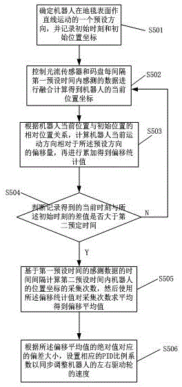
本发明实施例提供一种机器人运动的地毯偏移的控制方法,该控制方法应用于机器人在地毯表面运动过程,如图5所示,该控制方法包括:An embodiment of the present invention provides a method for controlling the displacement of a carpet when a robot moves. The control method is applied to the movement process of the robot on the carpet surface. As shown in FIG. 5 , the control method includes:
步骤S501、当控制主板2检测机器人到在地毯表面运动后,控制机器人在地毯表面沿预设方向作直线运动,其中预设方向为全局坐标系YOX的X轴或Y轴的正方向,同时启动记录时间、机器人的位置坐标,从而获取机器人的初始位置坐标和初始时刻。在本发明实施例中,控制机器人沿着全局坐标系YOX的X轴正方向作直线运动,X轴正方向为机器人期望位移方向。在运动过程中由于地毯纹理方向等作用力而导致地毯偏移现象,故需不断更新位置坐标和记录的时间变量,并进入步骤S502。Step S501, after the
需要说明的是,机器人偏离角度为基于陀螺仪检测角度而计算得到的机器人当前位置与初始位置的角度差。机器人在执行所述步骤S501之前,机器人的左驱动轮的速度等于右驱动轮的速度。理论上,机器人想要沿直线行走,输出到两个驱动轮的控制速度应该是相同的,但是,由于地毯施加的作用力带来地毯偏移,会导致机器人的左驱动轮和右驱动轮的实际行走速度出现偏差,从而导致机器人会向待行走直线的一侧偏离。It should be noted that the deviation angle of the robot is the angle difference between the current position of the robot and the initial position calculated based on the angle detected by the gyroscope. Before the robot performs the step S501, the speed of the left driving wheel of the robot is equal to the speed of the right driving wheel. Theoretically, if the robot wants to walk in a straight line, the control speed output to the two driving wheels should be the same. However, due to the force exerted by the carpet, the carpet is offset, which will cause the left and right driving wheels of the robot. The actual walking speed deviates, causing the robot to deviate to the side of the straight line to be walked.
步骤S502、根据第一预设时间内传感器融合计算得到机器人的当前位置坐标,每间隔第一预设时间将光流传感器感测的数据和同一时间内码盘感测的数据进行融合计算,得到机器人的当前位置坐标,即机器人中心坐标,对应地毯上机器人的驱动轮前进的实际路程,并进入步骤S503。在本发明实施例中,所述第一预设时间优选地设置为10ms,作为传感器感测每一个数据的时间间隔。具体地,机器人沿着X轴正方向在地毯表面运动过程中,将光流传感器每个10ms内的感测数据在时间维度上进行积分计算,再从光流坐标系转换到机器坐标系得到机器人中心坐标,对应机器人中心所在的全局坐标位置RO;将码盘每个10ms内的感测数据在时间维度上进行积分计算,再从机器坐标系转换到光流坐标系得到光流偏移位置坐标,即光流传感器的偏移坐标。Step S502, obtaining the current position coordinates of the robot according to the sensor fusion calculation within the first preset time, and performing fusion calculation on the data sensed by the optical flow sensor and the data sensed by the code disc in the same time interval every first preset time to obtain The coordinates of the current position of the robot, that is, the coordinates of the center of the robot, correspond to the actual distance traveled by the driving wheels of the robot on the carpet, and step S503 is entered. In this embodiment of the present invention, the first preset time is preferably set to 10ms, which is used as a time interval for the sensor to sense each data. Specifically, during the movement of the robot on the carpet surface along the positive direction of the X-axis, the sensing data of the optical flow sensor within each 10ms is integrated in the time dimension, and then converted from the optical flow coordinate system to the machine coordinate system to obtain the robot. The center coordinate corresponds to the global coordinate position RO where the robot center is located; the sensing data within each 10ms of the code disc is integrated in the time dimension, and then converted from the machine coordinate system to the optical flow coordinate system to obtain the optical flow offset position coordinates , that is, the offset coordinates of the optical flow sensor.
需要说明的是,如果机器人初始位姿、环境及目标已知,导航问题转化为全局路径规划问题,故机器人的码盘和光流传感器感测的坐标都需要转换到全局坐标系下再进行融合计算,并且最终得到的机器人的当前位置坐标为全局坐标系下的位置坐标。It should be noted that if the initial pose, environment and target of the robot are known, the navigation problem is transformed into a global path planning problem. Therefore, the coordinates sensed by the robot's code wheel and optical flow sensor need to be converted to the global coordinate system before fusion calculation. , and the current position coordinates of the robot finally obtained are the position coordinates in the global coordinate system.
具体地,机器人坐标系、光流坐标系和全局坐标系的分布示意图如图2所示,机器人坐标系是以当前位置下机器人中心RO为原点,对应当前位置下机器人前进方向为R_X轴正方向的坐标系,机器人坐标系还包括垂直于R_X轴方向的R_Y轴;机器人坐标系中心R0对应于放置在机器人中心的控制主板2中心位置的陀螺仪3。全局坐标系是以机器人初始位置为原点、以机器人从初始位置出发的前进方向为X轴正方向、以垂直于X轴方向为Y轴的坐标系;光流坐标系为像素坐标系,与机器人坐标系和全局坐标系的单位不同,是以光流模块7的中心位置PO为原点、相互垂直的P_X轴和P_Y轴为坐标轴的坐标系。上述三个坐标系都遵从右手定则;其中机器人坐标系和光流坐标系都是相对坐标系,其原点随着机器人当前位置的变化而变化。在所述全局坐标系中,Y轴左侧为第一象限,逆时针旋转依次为第二象限,第三象限,第四象限,其中所述机器人运动方向偏离所述预设方向的角度的绝对值保持设定为θ1。Specifically, the schematic diagram of the distribution of the robot coordinate system, the optical flow coordinate system and the global coordinate system is shown in Figure 2. The robot coordinate system takes the robot center RO at the current position as the origin, and the robot's forward direction corresponding to the current position is the positive direction of the R_X axis The robot coordinate system also includes the R_Y axis perpendicular to the R_X axis direction; the center R0 of the robot coordinate system corresponds to the
具体地,光流模块7上光流传感器通过一定速率连续采集物体表面图像,再由机器人的控制主板2对所产生的图像像素点进行分析。由于相邻的两幅图像总会存在相同的特征,所以通过对比这些特征点的位置变化信息,便可以判断出物体表面特征的平均运动;然后根据同一像素点灰度不变原则及同一图像区域内像素点速度相同原则,建立光流场方程并求解得到像素点的运动速度,然后进行积分计算,从而利用所述光流传感器获取的图像特征信息积分计算出机器人在所述第一预设时间内获取的图像位移量,而图像位移量为光流坐标系下的数值,其单位需转换为里程距离单位,故把图像位移量转化为与码盘相同量纲的位移量。Specifically, the optical flow sensor on the
作为本发明实施例,光流传感器与机器人中心的刚性连接关系是光流传感器的光流坐标系和机器人中心的机器坐标系的相对位置关系,包括光流传感器的位置与机器人中心位置的距离大小、光流传感器的位置与机器人中心位置的连线与机器坐标系的预设坐标轴的夹角;其中,机器坐标系的预设坐标轴正方向为机器人当前运动方向;机器坐标系的预设坐标轴正方向与全局坐标系的预设坐标轴正方向的夹角是基于陀螺仪检测数值计算得到,作为机器人当前位置相对于所述预设方向的偏离角度。如图2和图4所示,机器人坐标系的原点RO与光流坐标系的原点PO的相对位置关系是所述光流传感器与所述惯性传感器的刚体连接关系,包括机器人坐标系的原点RO与光流坐标系的原点PO的距离L,以及线段PORO与机器人坐标系的R_X轴所在直线的夹角绝对值为θ,机器人坐标系与光流坐标系的相对位置关系在机器人运动过程中保持不变以形成所述刚体连接关系,机器人坐标系的原点RO的实际位置对应于放置于机器人中心位置的陀螺仪3,光流坐标系的原点PO的实际位置对应于光流模块7。As an embodiment of the present invention, the rigid connection relationship between the optical flow sensor and the robot center is the relative positional relationship between the optical flow coordinate system of the optical flow sensor and the machine coordinate system of the robot center, including the distance between the position of the optical flow sensor and the robot center position. , the angle between the line connecting the position of the optical flow sensor and the center position of the robot and the preset coordinate axis of the machine coordinate system; wherein, the positive direction of the preset coordinate axis of the machine coordinate system is the current motion direction of the robot; the preset coordinate axis of the machine coordinate system The angle between the positive direction of the coordinate axis and the positive direction of the preset coordinate axis of the global coordinate system is calculated based on the value detected by the gyroscope, and is used as the deviation angle of the current position of the robot relative to the preset direction. As shown in Figures 2 and 4, the relative positional relationship between the origin RO of the robot coordinate system and the origin PO of the optical flow coordinate system is the rigid connection relationship between the optical flow sensor and the inertial sensor, including the origin RO of the robot coordinate system The absolute value of the distance L from the origin PO of the optical flow coordinate system and the angle between the line segment PORO and the line where the R_X axis of the robot coordinate system is located is θ, and the relative positional relationship between the robot coordinate system and the optical flow coordinate system is maintained during the movement of the robot. Unchanged to form the rigid body connection relationship, the actual position of the origin RO of the robot coordinate system corresponds to the
如图4所示,基于上述刚性连接关系的坐标系转换方法:机器人中心位置R0处于全局坐标系的第四象限内,光流模块7上的光流传感器感测到光流坐标系下的坐标,转换到全局坐标系得到所述第一预测位置坐标PO(xp4,yp4),位于全局坐标系的第四象限内,即机器人当前运动方向往Y轴负方向偏离X轴正方向的角度为θ1,该角度是机器人受地毯的作用力引起的固定偏移角度,可由陀螺仪3感测到机器人转动角度θ1。根据三角函数关系式将所述第一预测位置坐标按照所述刚体连接关系平移换算得到机器人中心所在位置下得到第二预测位置坐标,即机器人中心在全局坐标系下的当前位置坐标RO(xr4,yr4),可以由第四象限的示例性公式近似表示:As shown in Figure 4, the coordinate system conversion method based on the above rigid connection relationship: the robot center position R0 is in the fourth quadrant of the global coordinate system, and the optical flow sensor on the


上述公式适用的具体实施例为:陀螺仪3位于机器人中心,光流模块7位于机器人中心的右下方。光流传感器测量得到的光流坐标偏移量经过前述坐标系转换方法得到机器人中心在全局坐标系下的当前位置坐标为RO(xr4,yr4),其机体重心偏离运动期望位置(xr4,0)的角度为θ1。A specific embodiment to which the above formula is applicable is: the
需要说明的是,机器人中心位置还包括处于全局坐标系的第一象限、第二象限和第三象限的实施例。在这些实施例中,陀螺仪3位于机器人中心,光流模块7位于机器人中心的右下方,机器人的期望位移方向为X轴正方向,即所述预设方向为X轴正方向。It should be noted that the center position of the robot also includes the embodiments in the first quadrant, the second quadrant and the third quadrant of the global coordinate system. In these embodiments, the
机器人中心位置R1处于全局坐标系的第一象限内的实施例:所述第一预测位置坐标P1(xp1,yp1),根据三角函数关系式将所述第一预测位置坐标按照所述刚体连接关系平移换算得到机器人中心所在位置下得到第二预测位置坐标,即机器人中心在全局坐标系第一象限内的当前位置坐标R1(xr1,yr1),在所述第四象限的基础上,由三角函数关系式近似表示:The embodiment in which the center position R1 of the robot is located in the first quadrant of the global coordinate system: the first predicted position coordinates P1 (xp1, yp1), the first predicted position coordinates are determined according to the rigid body connection relationship according to the trigonometric function relationship The second predicted position coordinates are obtained under the position of the robot center by translation conversion, that is, the current position coordinates R1 (xr1, yr1) of the robot center in the first quadrant of the global coordinate system. On the basis of the fourth quadrant, the trigonometric function The relational expression approximates:

yr1=xr1×tanθ1。yr1=xr1×tanθ1.
机器人中心位置R2处于全局坐标系的第二象限内的实施例:所述第一预测位置坐标P2(xp2,yp2),根据三角函数关系式将所述第一预测位置坐标按照所述刚体连接关系平移换算得到机器人中心所在位置下得到第二预测位置坐标,即机器人中心在全局坐标系第二象限内的当前位置坐标R2(xr2,yr2),可以由以下示例性公式近似表示:The embodiment in which the robot center position R2 is in the second quadrant of the global coordinate system: the first predicted position coordinates P2 (xp2, yp2), according to the trigonometric function relationship, the first predicted position coordinates according to the rigid body connection relationship The second predicted position coordinates are obtained under the position where the robot center is obtained by translation conversion, that is, the current position coordinates R2 (xr2, yr2) of the robot center in the second quadrant of the global coordinate system, which can be approximated by the following exemplary formula:

yr2=-xr2×tanθ1。yr2=-xr2×tanθ1.
机器人中心位置R3处于全局坐标系的第三象限内的实施例,所述第一预测位置坐标P3(xp3,yp3),根据三角函数关系式将所述第一预测位置坐标按照所述刚体连接关系平移换算得到机器人中心所在位置下得到第二预测位置坐标,即机器人中心在全局坐标系第三象限内的当前位置坐标R3(xr3,yr3),可以由以下示例性公式近似表示:The embodiment of the robot center position R3 in the third quadrant of the global coordinate system, the first predicted position coordinates P3 (xp3, yp3), according to the trigonometric function relationship, the first predicted position coordinates according to the rigid body connection relationship The second predicted position coordinates obtained under the position of the robot center obtained by translation conversion, that is, the current position coordinates R3 (xr3, yr3) of the robot center in the third quadrant of the global coordinate system, can be approximated by the following exemplary formula:

yr3=xr3×tanθ1。yr3=xr3×tanθ1.
另外,如果机器人的期望位移方向不是X轴正方向,即所述预设方向不是X轴正方向,或者,光流模块7不位于机器人中心的右下方,则按照由第四象限的示例性公式的思路,并结合相应的三角函数关系计算得出机器人的中心位置坐标,它们的坐标系转换方法的发明构思是相同的,故在这里不再赘述上述期望位移方向和光流模块7的位置的其他实施例。In addition, if the desired displacement direction of the robot is not the positive direction of the X-axis, that is, the preset direction is not the positive direction of the X-axis, or, the
作为本发明实施例,由于光流传感器提高机器人的位置准确性,但光流传感器的感测数据不一定可靠,故需要借助码盘数据进行所述融合计算。具体地,当光流传感器输出的中断信号为高电平,则光流传感器的感测数据可靠;当光流传感器输出的中断信号为低电平,则光流传感器的感测数据不可靠;其中,所述中断信号为光流传感器内置算法处理感测数据而得到的结果,所述内置算法为现有技术中处理地毯表面的图像数据的常见算法,故不再赘述。As an embodiment of the present invention, since the optical flow sensor improves the position accuracy of the robot, the sensing data of the optical flow sensor is not necessarily reliable, so the fusion calculation needs to be performed with the help of the code disc data. Specifically, when the interrupt signal output by the optical flow sensor is at a high level, the sensing data of the optical flow sensor is reliable; when the interrupt signal output by the optical flow sensor is at a low level, the sensing data of the optical flow sensor is unreliable; Wherein, the interrupt signal is a result obtained by processing the sensed data with a built-in algorithm of the optical flow sensor, and the built-in algorithm is a common algorithm for processing image data of a carpet surface in the prior art, so it is not repeated here.
所述步骤S502中的融合计算包括,如图6所示:The fusion calculation in the step S502 includes, as shown in Figure 6:
步骤S601:码盘感测脉冲数据,同时光流传感器感测光流数据,然后进入步骤S602。Step S601: the code disc senses the pulse data, and the optical flow sensor senses the optical flow data, and then proceeds to step S602.
步骤S602:判断光流传感器的感测数据是否可靠,是则进入步骤S603,否则进入步骤S606。Step S602: Determine whether the sensing data of the optical flow sensor is reliable, if yes, go to Step S603, otherwise go to Step S606.
步骤S603:将光流传感器在每个所述第一预设时间内获取的图像位移量转化为与码盘相同量纲的位移量,具体地,使用所述光流数据更新地图坐标时,将所述码盘的单个脉冲周期内所测量的距离数值与所述光流传感器在相同脉冲周期内的相对坐标的偏移量数值的比值作为单位换算系数,再将所述光流数据乘上该单位换算系数,得到单位统一后的数值。然后将每个所述第一预设时间内光流传感器的感测数据进行累加实现时间维度上的积分计算,从而得出光流传感器相对于其起始位置的光流偏移位置坐标,即对应光流传感器当前输出的测量结果。然后进入步骤S604。Step S603: Convert the image displacement obtained by the optical flow sensor in each of the first preset time into the displacement of the same dimension as the code disc. Specifically, when using the optical flow data to update the map coordinates, the The ratio of the distance value measured in a single pulse period of the code wheel and the offset value of the relative coordinates of the optical flow sensor in the same pulse period is used as a unit conversion factor, and then the optical flow data is multiplied by this value. Unit conversion factor to get the value after the unit is unified. Then, the sensing data of the optical flow sensor in each first preset time is accumulated to realize the integral calculation in the time dimension, so as to obtain the optical flow offset position coordinates of the optical flow sensor relative to its starting position, that is, the corresponding The measurement result currently output by the optical flow sensor. Then go to step S604.
步骤S604:根据光流传感器与机器人中心的刚性连接关系所揭示的前述示例性公式,即根据机器人坐标系与光流坐标系的距离角度关系构建的三角几何关系,将所述光流偏移位置坐标按照前述坐标系转换方法进行平移换算,得到机器人位置坐标,对应地毯上机器人的驱动轮前进的实际路程,然后进入步骤S605;Step S604: According to the aforementioned exemplary formula revealed by the rigid connection relationship between the optical flow sensor and the center of the robot, that is, the triangular geometric relationship constructed according to the distance and angle relationship between the robot coordinate system and the optical flow coordinate system, the optical flow is shifted to a position. The coordinates are translated and converted according to the aforementioned coordinate system conversion method to obtain the position coordinates of the robot, which correspond to the actual distance traveled by the driving wheels of the robot on the carpet, and then enter step S605;
步骤S605:步骤S604得到的机器人位置坐标更新码盘当前输出的坐标数据。然后返回步骤S601。相对于未融合处理前码盘输出的测量结果,该步骤融合计算的结果更加可靠稳定。Step S605: The robot position coordinates obtained in step S604 update the coordinate data currently output by the code wheel. Then it returns to step S601. Compared with the measurement result output by the code disc before the fusion processing, the result of the fusion calculation in this step is more reliable and stable.
步骤S606:对码盘感测的脉冲数据进行时间维度积分,从而得到所述机器人中心坐标,该坐标数据会在下一次进入步骤S605中被所述机器人位置坐标更新。然后进入步骤S607。由于码盘通过每秒产生的脉冲个数来记录机器人的运动速度,所以将码盘在每个所述第一预设时间内感测的脉冲数据在时间维度上进行积分计算,得到机器人的当前位置坐标,对应地毯上机器人的驱动轮前进的实际路程。Step S606: Integrate the pulse data sensed by the encoder in the time dimension to obtain the robot center coordinates, and the coordinate data will be updated by the robot position coordinates in the next step S605. Then go to step S607. Since the code disc records the motion speed of the robot through the number of pulses generated per second, the pulse data sensed by the code disc in each of the first preset time is integrated in the time dimension to obtain the current The position coordinates correspond to the actual distance traveled by the driving wheel of the robot on the carpet.
步骤S607:将步骤S606中所述积分计算的结果更新码盘当前输出的坐标数据。然后进入步骤S608。在更新步骤S604中所述机器中心坐标之前,由于步骤S604中所述机器中心坐标可以是光流传感器的感测数据可靠的阶段所感测数据积分转换的结果(光流传感器在感测数据可靠的阶段所输出的测量结果),所以所述的更新操作保证测得的机器人的位置坐标的准确性。同时根据光流传感器与机器人中心的刚性连接关系所揭示的前述示例性公式的逆运算公式,即根据机器人坐标系与光流坐标系的距离角度关系构建的三角几何关系,将所述机器中心坐标按照前述坐标系转换方法进行逆换算,得到光流传感器当前的偏移位置坐标。Step S607: Update the coordinate data currently output by the code wheel with the result of the integral calculation in step S606. Then go to step S608. Before updating the machine center coordinates in step S604, since the machine center coordinates in step S604 may be the result of integral conversion of the sensed data in the stage when the sensed data of the optical flow sensor is reliable (the optical flow sensor is reliable in the sensed data) The measurement results output by the stage), so the update operation guarantees the accuracy of the measured position coordinates of the robot. At the same time, according to the inverse operation formula of the above-mentioned exemplary formula revealed by the rigid connection relationship between the optical flow sensor and the robot center, that is, the triangular geometric relationship constructed according to the distance and angle relationship between the robot coordinate system and the optical flow coordinate system, the coordinates of the machine center are Inverse conversion is performed according to the aforementioned coordinate system conversion method to obtain the current offset position coordinates of the optical flow sensor.
步骤S608:将步骤S607中得到的光流传感器的偏移坐标更新光流传感器当前输出的坐标数据。然后返回步骤S601。由于所述光流偏移位置坐标可以是光流传感器的感测数据进行累加实现时间维度上的积分计算结果,但由于存在光流传感器的感测数据不可靠的情况,所以需将步骤S606中码盘感测的脉冲数据积分得到的所述机器中心坐标进行平移换算,并将平移换算的结果更新步骤S603中计算得到的所述光流偏移位置坐标,以提高光流传感器的感测数据可靠时光流传感器的感测数据积分运算的准确性。Step S608: Update the coordinate data currently output by the optical flow sensor with the offset coordinates of the optical flow sensor obtained in step S607. Then it returns to step S601. Since the optical flow offset position coordinates may be the sensing data of the optical flow sensor to be accumulated to realize the integral calculation result in the time dimension, but since the sensing data of the optical flow sensor is unreliable, it is necessary to change the data in step S606 The machine center coordinates obtained by integrating the pulse data sensed by the code disc are translated and converted, and the result of the translation conversion is updated to the optical flow offset position coordinates calculated in step S603 to improve the sensing data of the optical flow sensor. Reliable accuracy of the integration operation of the sensing data of the optical flow sensor.
本发明实施例通过内置的光流传感器与码盘实时感测的数据进行可靠性判断,然后根据传感器可靠性判断的结果选择其中一种传感器的感测数据转换到光流坐标系下进行积分运算以求得更为准确的地毯上机器人的驱动轮前进的实际路程,减小地毯偏移所带来的作用力效果的误差。In the embodiment of the present invention, the reliability is judged by the built-in optical flow sensor and the real-time sensing data of the code disc, and then the sensing data of one of the sensors is selected according to the result of the reliability judgment of the sensor, and the sensing data is converted into the optical flow coordinate system for integral operation. In order to obtain a more accurate actual distance of the driving wheel of the robot on the carpet, and reduce the error of the force effect caused by the offset of the carpet.
步骤S503、根据机器人当前位置坐标与初始位置坐标的相对位置关系,计算机器人当前运动方向相对于所述预设方向的偏移量,再进行累加得到偏移统计值,然后进入步骤S504;其中偏移量为机器人当前位置与所述预设方向所在直线的垂直距离。由于地毯的作用力导致机器人发生转动,因此,如图4所示机器人实际位移方向OR0偏离期望位移方向OM,则当前位置坐标相对于期望的X轴正方向的偏移量为yr-y0。然后对上述计算得到的多组偏移量进行累加得到偏移统计值。Step S503: Calculate the offset of the robot's current movement direction relative to the preset direction according to the relative positional relationship between the robot's current position coordinates and the initial position coordinates, and then accumulate to obtain a statistical value of the offset, and then enter step S504; The displacement is the vertical distance between the current position of the robot and the straight line where the preset direction is located. Because the force of the carpet causes the robot to rotate, as shown in Figure 4, the actual displacement direction OR0 of the robot deviates from the desired displacement direction OM, and the offset of the current position coordinates relative to the desired positive X-axis direction is yr-y0. Then, the multiple sets of offsets calculated above are accumulated to obtain offset statistics.
步骤S504、判断记录得到的当前时刻与所述初始时刻的差值是否大于第二预设时间,是则进入步骤S505,否则返回步骤S502。在本发明实施例中,第二预设时间优选地设置为500ms,作为检测机器人发生地毯偏移所耗费的时间。在所述第二预设时间内,机器人的左驱动轮11和右驱动轮12在地毯表面所受到的作用力方向会因地毯纹理作用而改变,使得地毯偏移方向在所述第二预设时间内会不断发生变化,所述偏移量在正负值之间变化,故需要采集多组偏移量进行累加求和再进行判断所述第二预设时间内机器人准确的地毯偏移方向。其中,所述第二预设时间是确定机器人发生地毯偏移的检测时间。Step S504 , judging whether the difference between the recorded current time and the initial time is greater than the second preset time, if yes, go to step S505 , otherwise return to step S502 . In the embodiment of the present invention, the second preset time is preferably set to 500ms, which is the time taken to detect the carpet deviation of the robot. During the second preset time, the direction of the force applied to the carpet surface by the
步骤S505、根据所述第二预设时间计算所述第一预设时间内机器人的位置坐标的采集次数,然后使用所述偏移统计值对采集次数求平均得到偏移平均值,作为地毯偏移量,并进入步骤S506;在本发明实施例中,所述第二预设时间优选地设置为500ms,所述第一预设时间优选地设置为10ms,故所述第二预设时间内机器人的位置坐标的采集次数为50次,然后对50次累加得到的所述偏移统计值求平均值,从而得到偏移平均值,作为地毯偏移量。由于机器在地毯表面偏移方向和幅度不稳定,故本发明实施例对10ms时间间隔内获取的位置坐标进行50次采样,并累加处理以得到500ms内的一个确定的地毯偏移量,提高所述地毯偏移量的鲁棒性;进一步地,由于求取地毯偏移量使用所述光流传感器的光流坐标数据及50次的统计值,可能存在误差变量的干扰,故为提高所述地毯偏移量的检测精度,需进一步地对所述偏移统计值求平均值,整个数据运算处理比较简易,并容易得到较为准确的地毯偏移量。具体地,根据所述偏移平均值确定机器人当前运动方向偏离所述预设方向的程度,相应地,所述偏移平均值的正负与所述全局坐标系上机器人偏离的坐标轴方向相关,所述偏移平均值的数值大小确定机器人当前运动方向偏离所述预设方向的幅度。Step S505: Calculate the collection times of the position coordinates of the robot within the first preset time according to the second preset time, and then use the offset statistical value to average the collection times to obtain an average offset value, which is used as the carpet offset. shift amount, and enter step S506; in the embodiment of the present invention, the second preset time is preferably set to 500ms, and the first preset time is preferably set to 10ms, so the second preset time is preferably set to 10ms. The number of times of collecting the position coordinates of the robot is 50 times, and then the average value of the offset statistics obtained by the accumulation of 50 times is averaged, so as to obtain the average value of the offset, which is used as the offset of the carpet. Since the machine is unstable in the direction and amplitude of the offset of the carpet surface, the embodiment of the present invention samples the position coordinates obtained within a time interval of 10ms for 50 times, and accumulates them to obtain a certain offset of the carpet within 500ms, thereby improving the overall The robustness of the carpet offset; further, since the optical flow coordinate data of the optical flow sensor and the 50th statistical value of the optical flow sensor are used to obtain the carpet offset, there may be interference of error variables, so in order to improve the For the detection accuracy of the carpet offset, it is necessary to further average the offset statistic values. The entire data operation and processing is relatively simple, and it is easy to obtain a relatively accurate carpet offset. Specifically, the degree to which the robot's current movement direction deviates from the preset direction is determined according to the offset average value. Accordingly, the positive and negative of the offset average value are related to the coordinate axis direction of the robot's deviation on the global coordinate system. , the magnitude of the average value of the deviation determines the magnitude of the deviation of the current movement direction of the robot from the preset direction.
进一步地,所述偏移量、所述偏移统计值和所述采集次数在所述初始时刻都初始化为零。第一预设时间是完成一次融合计算的更新时间;第二预设时间是确定机器人发生地毯偏移的检测时间;机器人的初始位置和当前位置坐标都是全局坐标。Further, the offset amount, the offset statistic value and the collection times are all initialized to zero at the initial moment. The first preset time is the update time for completing one fusion calculation; the second preset time is the detection time for determining the carpet deviation of the robot; the initial position and current position coordinates of the robot are global coordinates.
步骤S506、根据所述偏移平均值的绝对值对应的偏差大小,设置相应的PID比例系数以同步调整机器人的左右驱动轮的速度,使得机器人从当前运动方向修正回所述预设方向上继续做直线运动。Step S506, according to the deviation corresponding to the absolute value of the offset average value, set the corresponding PID proportional coefficient to synchronously adjust the speed of the left and right driving wheels of the robot, so that the robot is corrected from the current movement direction back to the preset direction to continue. Do a straight line movement.
具体地,确定机器人当前运动方向已偏离所述预设方向后,则控制实施以下步骤:当所述偏移平均值
当所述偏移平均值
作为一种实施例,机器人还根据陀螺仪的角度变化来判断其在地毯表面的偏移角度及方向,即机器人在所述当前位置坐标与所述初始位置坐标处陀螺仪测得的角度差。在本发明实施例中,如图3所示,当所述偏移平均值为正数,则确定机器人往全局坐标系的Y轴正方向偏移,偏移幅度大小为所述偏移平均值,再结合陀螺仪测量得到的角度变化可知机器人偏移往全局坐标系的Y轴正方向偏移的角度大小,从而确定机器人受到的地毯作用力的合力矢量值;当所述偏移平均值为负数,则确定机器人往全局坐标系的Y轴负方向偏移,偏移幅度大小为所述偏移平均值的绝对值,再结合陀螺仪测量得到的角度变化可知机器人偏移往全局坐标系的Y轴负方向偏移的角度大小,从而确定机器人受到的地毯作用力的合力矢量值。如果所述期望位移方向是所述全局坐标系的X轴正方向时,所述偏移平均值的正负与所述全局坐标系上机器人偏离的坐标轴方向相关。As an embodiment, the robot also judges its offset angle and direction on the carpet surface according to the angle change of the gyroscope, that is, the angle difference measured by the gyroscope at the coordinates of the current position of the robot and the coordinates of the initial position. In the embodiment of the present invention, as shown in FIG. 3 , when the average value of the offset is a positive number, it is determined that the robot is offset in the positive direction of the Y-axis of the global coordinate system, and the magnitude of the offset is the average value of the offset , and then combined with the angle change measured by the gyroscope, we can know the angle of the robot offset to the positive direction of the Y axis of the global coordinate system, so as to determine the resultant force vector value of the carpet force received by the robot; when the average value of the offset is Negative number, it is determined that the robot is offset in the negative direction of the Y-axis of the global coordinate system, and the magnitude of the offset is the absolute value of the average value of the offset. Combined with the angle change measured by the gyroscope, it can be known that the robot is offset to the global coordinate system. The magnitude of the angle offset in the negative direction of the Y axis, thereby determining the resultant force vector value of the carpet force on the robot. If the desired displacement direction is the positive direction of the X-axis of the global coordinate system, the positive and negative of the average value of the offset is related to the coordinate axis direction of the robot's deviation on the global coordinate system.
作为本发明其中一个实施例,当所述偏移平均值


作为本发明另一个实施例,当所述偏移平均值


由于,机器人要调整右驱动轮的速度,就需要向右驱动轮的电机输入不同的PWM驱动信号,所以,基于PID控制算法,为了达到较好的调整效果,需要预先获取当前时刻和邻近当前时刻的前两个时刻的机器人的右驱动轮的控制速度和采样速度。比如,获取到当前时刻和当前时刻前1秒以及当前时刻前2秒的控制速度和采样速度。其中,控制速度是系统输出数据,而采样速度则是通过码盘检测到的数据。由于外界环境的影响,实际的采样速度与系统输出的控制速度是有所偏差的。所以,在确定了不同时刻两者的误差数据之后,再结合PID的数值,就可以准确的得到输出至右驱动轮以调整右驱动轮的速度的电压值。其中,P、I和D的值是通过对机器人进行有限次的实验、测试和总结而得到的,分别为一个常数。本实施例所述的方法,通过PID控制算法,可以准确得到输出至右驱动轮的电机的电压值,控制精度高,控制效果较好。Since the robot needs to input different PWM drive signals to the motor of the right drive wheel to adjust the speed of the right drive wheel, based on the PID control algorithm, in order to achieve a better adjustment effect, it is necessary to obtain the current moment and the adjacent current moment in advance The control speed and sampling speed of the robot's right drive wheel at the first two moments. For example, the control speed and sampling speed of the current time, 1 second before the current time, and 2 seconds before the current time are obtained. Among them, the control speed is the system output data, and the sampling speed is the data detected by the code disc. Due to the influence of the external environment, the actual sampling speed deviates from the control speed of the system output. Therefore, after determining the error data of the two at different times, combined with the PID value, the voltage value output to the right drive wheel to adjust the speed of the right drive wheel can be accurately obtained. Among them, the values of P, I, and D are obtained by performing a limited number of experiments, tests, and summaries on the robot, and are respectively a constant. In the method described in this embodiment, through the PID control algorithm, the voltage value of the motor output to the right driving wheel can be accurately obtained, the control precision is high, and the control effect is good.
一种芯片,用于存储程序,所述程序用于控制机器人执行所述控制方法,以实现机器人在地毯表面上的智能化清扫,提高清扫效率。所述芯片通过光流传感器、陀螺仪和码盘来确定待行走的直线的初始位置信息(X1,Y1,θ1)和机器人行走过程中具体的当前位置信息(X2,Y2,θ2),再由初始位置信息中的角度θ1与当前位置信息中的角度θ2的差值以及当前位置偏离所述预设方向所在的直线的垂直距离,来判断机器人的行走是否偏离了所述直线。如果出现偏离,则通过调整机器人的驱动轮的速度,使机器人回到所述直线上。A chip is used to store a program, and the program is used to control a robot to execute the control method, so as to realize the intelligent cleaning of the robot on the carpet surface and improve the cleaning efficiency. The chip determines the initial position information (X1, Y1, θ1) of the straight line to be walked and the specific current position information (X2, Y2, θ2) during the walking process of the robot through an optical flow sensor, a gyroscope and a code disc, and then uses The difference between the angle θ1 in the initial position information and the angle θ2 in the current position information and the vertical distance of the current position deviating from the straight line in which the preset direction is located are used to determine whether the walking of the robot deviates from the straight line. If deviation occurs, the robot is brought back on the straight line by adjusting the speed of the robot's drive wheels.
一种清洁机器人,该清洁机器人是一种用于清扫地毯表面的机器人。在本发明实施例中,在地毯上运动的机器人可以是扫地机器人,扫地机器人可以根据所述地毯偏移量在地毯上动态调整机器人的运动参数,从而有利于调整不同材质的地毯表面或地毯边缘的清扫距离间距;另外通过扫地机器人内置的PID调节系统将发生地毯偏移的扫地机器人修正回直线运动以完成沿边清扫。A cleaning robot is a robot for cleaning carpet surfaces. In this embodiment of the present invention, the robot moving on the carpet may be a sweeping robot, and the sweeping robot can dynamically adjust the motion parameters of the robot on the carpet according to the carpet offset, which is beneficial to adjust the carpet surface or carpet edge of different materials In addition, through the built-in PID adjustment system of the sweeping robot, the sweeping robot with carpet deviation is corrected back to a linear motion to complete the edge cleaning.
所述方法通过光流传感器、陀螺仪和码盘来确定待行走的直线的初始位置信息(X1,Y1,θ1)和机器人行走过程中具体的当前位置信息(X2,Y2,θ2),再由初始位置信息中的角度θ1与当前位置信息中的角度θ2的差值以及当前位置偏离待行走直线的垂直距离,来判断机器人的行走是否偏离了待行走直线。如果出现偏离,则通过调整机器人的驱动轮的速度,使机器人回到所述期望位移方向上。这种机器人走直线的控制方法,仅需要借助光流传感器和码盘的检测数据并融合数据,就可以判断机器人在地毯上行走是否出现偏离期望位移方向,并根据偏差的数值可以有效地控制机器人纠正偏差,从而保持较好的直线行走效果,成本相对较低。同时,关于偏差的检测和纠正的相关数据比较准确,数据运算处理也比较简易,不需要高性能的处理器,进一步减小了系统运算资源和处理器的硬件成本。The method determines the initial position information (X1, Y1, θ1) of the straight line to be walked and the specific current position information (X2, Y2, θ2) during the walking process of the robot through an optical flow sensor, a gyroscope and a code disc, and then uses The difference between the angle θ1 in the initial position information and the angle θ2 in the current position information and the vertical distance that the current position deviates from the straight line to be walked is used to determine whether the robot's walking deviates from the straight line to be walked. If deviation occurs, the robot is returned to the desired displacement direction by adjusting the speed of the robot's drive wheels. This control method of the robot walking in a straight line only needs to use the detection data of the optical flow sensor and the code disc and fuse the data to judge whether the robot walks on the carpet deviates from the desired displacement direction, and can effectively control the robot according to the deviation value. Correct the deviation, so as to maintain a good straight walking effect, and the cost is relatively low. At the same time, the data related to the detection and correction of deviations are relatively accurate, and the data operation processing is relatively simple, and high-performance processors are not required, which further reduces the system computing resources and the hardware costs of the processors.
装配所述芯片作为控制芯片的清洁机器人,仅需要借助光流传感器和码盘的检测数据,就可以判断机器人行走是否出现偏差,并根据偏差的数值可以有效地控制机器人纠正偏差,从而保持较好的直线行走效果,成本相对较低。同时,关于偏差的检测和纠正的相关数据比较简明,数据运算处理也比较简易,不需要高性能的处理器,进一步减小了系统运算资源和机器人的硬件成本。The cleaning robot that assembles the chip as the control chip only needs to use the detection data of the optical flow sensor and the code disc to determine whether the robot walks with deviation, and according to the value of the deviation, the robot can be effectively controlled to correct the deviation, so as to maintain a good The straight-line walking effect is relatively low. At the same time, the data related to the detection and correction of deviations are relatively concise, and the data operation processing is relatively simple, and high-performance processors are not required, which further reduces the system computing resources and the hardware cost of the robot.
以上各实施例仅用以说明本发明的技术方案,而非对其限制;尽管参照前述各实施例对本发明进行了详细的说明,本领域的普通技术人员应当理解:其依然可以对前述各实施例所记载的技术方案进行修改,或者对其中部分或者全部技术特征进行等同替换;而这些修改或者替换,并不使相应技术方案的本质脱离本发明各实施例技术方案的范围。The above embodiments are only used to illustrate the technical solutions of the present invention, but not to limit them; although the present invention has been described in detail with reference to the foregoing embodiments, those of ordinary skill in the art should understand that the foregoing embodiments can still be used for The technical solutions described in the examples are modified, or some or all of the technical features thereof are equivalently replaced; and these modifications or replacements do not make the essence of the corresponding technical solutions depart from the scope of the technical solutions of the embodiments of the present invention.
Claims (8)
Priority Applications (6)
| Application Number | Priority Date | Filing Date | Title |
|---|---|---|---|
| CN201811240370.7A CN109394095B (en) | 2018-10-23 | 2018-10-23 | Robot movement carpet deviation control method, chip and cleaning robot |
| EP18937777.3A EP3871580B1 (en) | 2018-10-23 | 2018-12-19 | Control method for carpet-induced drift in robot movement, chip, and cleaning robot |
| JP2021521798A JP7165821B2 (en) | 2018-10-23 | 2018-12-19 | Control method, program and cleaning robot for carpet drift in robot motion |
| KR1020217015463A KR102502219B1 (en) | 2018-10-23 | 2018-12-19 | Drift control method due to carpet during robot movement, chip and cleaning robot |
| US17/288,002 US11918175B2 (en) | 2018-10-23 | 2018-12-19 | Control method for carpet drift in robot motion, chip, and cleaning robot |
| PCT/CN2018/121963 WO2020082552A1 (en) | 2018-10-23 | 2018-12-19 | Control method for carpet-induced drift in robot movement, chip, and cleaning robot |
Applications Claiming Priority (1)
| Application Number | Priority Date | Filing Date | Title |
|---|---|---|---|
| CN201811240370.7A CN109394095B (en) | 2018-10-23 | 2018-10-23 | Robot movement carpet deviation control method, chip and cleaning robot |
Publications (2)
| Publication Number | Publication Date |
|---|---|
| CN109394095A CN109394095A (en) | 2019-03-01 |
| CN109394095B true CN109394095B (en) | 2020-09-15 |
Family
ID=65469386
Family Applications (1)
| Application Number | Title | Priority Date | Filing Date |
|---|---|---|---|
| CN201811240370.7A Active CN109394095B (en) | 2018-10-23 | 2018-10-23 | Robot movement carpet deviation control method, chip and cleaning robot |
Country Status (6)
| Country | Link |
|---|---|
| US (1) | US11918175B2 (en) |
| EP (1) | EP3871580B1 (en) |
| JP (1) | JP7165821B2 (en) |
| KR (1) | KR102502219B1 (en) |
| CN (1) | CN109394095B (en) |
| WO (1) | WO2020082552A1 (en) |
Families Citing this family (18)
| Publication number | Priority date | Publication date | Assignee | Title |
|---|---|---|---|---|
| CN110448225B (en) * | 2019-07-01 | 2021-06-08 | 深圳拓邦股份有限公司 | Cleaning strategy adjusting method and system and cleaning equipment |
| JP7429902B2 (en) * | 2019-08-21 | 2024-02-09 | パナソニックIpマネジメント株式会社 | self-propelled robot |
| CN110840344B (en) * | 2019-09-30 | 2021-08-06 | 湖南格兰博智能科技有限责任公司 | Sweeping robot walking control system along line based on PID control algorithm and control method thereof |
| CN111053500B (en) * | 2020-01-02 | 2022-06-10 | 小狗电器互联网科技(北京)股份有限公司 | Method and device for controlling sweeping equipment to sweep along wall and sweeping equipment |
| CN111329395B (en) * | 2020-04-09 | 2021-07-13 | 湖南格兰博智能科技有限责任公司 | Sweeping robot edgewise sweeping method based on inertial navigation |
| CN113759305A (en) * | 2020-05-29 | 2021-12-07 | 同方威视技术股份有限公司 | Direction correction device and method for mobile radiation inspection device |
| CN112603204B (en) * | 2020-12-11 | 2022-07-12 | 深圳银星智能集团股份有限公司 | Method, device and equipment for track compensation and storage medium |
| CN113238555B (en) * | 2021-05-12 | 2024-07-12 | 珠海一微半导体股份有限公司 | Mobile robot with optical flow sensor and control method thereof |
| CN113344265B (en) * | 2021-05-28 | 2023-04-04 | 深圳市无限动力发展有限公司 | Track closure judging method and device, computer equipment and storage medium |
| CN113344263B (en) * | 2021-05-28 | 2022-12-27 | 深圳市无限动力发展有限公司 | Method and device for judging track closure in edge walking process and computer equipment |
| CN115700418B (en) * | 2021-07-16 | 2025-03-18 | 速感科技(北京)有限公司 | Ground material identification method, control method, device and storage medium |
| CN114001656B (en) * | 2021-11-12 | 2022-08-16 | 天津希格玛微电子技术有限公司 | Detection error correction method and device for optical displacement detection device |
| CN114587218B (en) * | 2021-12-31 | 2023-07-21 | 北京石头创新科技有限公司 | Method and device for judging the state of a cleaning robot |
| CN115342833B (en) * | 2022-07-20 | 2025-09-02 | 苏州艾吉威机器人有限公司 | Odometer automatic correction method and device |
| CN115268468B (en) * | 2022-09-27 | 2023-01-24 | 深圳市云鼠科技开发有限公司 | Method, device, equipment and medium for correcting wall-following coordinates of cleaning robot |
| CN115624298B (en) * | 2022-10-31 | 2025-12-02 | 珠海一微科技股份有限公司 | Methods for adjusting fan suction power in robots |
| CN116551689A (en) * | 2023-05-25 | 2023-08-08 | 山东新一代信息产业技术研究院有限公司 | A vision-based system and method for verifying the linear trajectory of a robot chassis |
| CN119620756B (en) * | 2024-12-02 | 2025-08-22 | 广东天朝达互联科技有限公司 | An automated inspection system for computer room operation and maintenance management |
Family Cites Families (20)
| Publication number | Priority date | Publication date | Assignee | Title |
|---|---|---|---|---|
| JP3076648B2 (en) * | 1992-01-10 | 2000-08-14 | 松下電器産業株式会社 | Self-propelled vacuum cleaner |
| KR100956537B1 (en) * | 2002-04-26 | 2010-05-07 | 혼다 기켄 고교 가부시키가이샤 | Magnetic Posture Estimator for Legged Mobile Robot |
| JP2005141636A (en) | 2003-11-10 | 2005-06-02 | Matsushita Electric Ind Co Ltd | Autonomous traveling device |
| US9250081B2 (en) | 2005-03-25 | 2016-02-02 | Irobot Corporation | Management of resources for SLAM in large environments |
| US8930023B2 (en) * | 2009-11-06 | 2015-01-06 | Irobot Corporation | Localization by learning of wave-signal distributions |
| JP2006313455A (en) * | 2005-05-09 | 2006-11-16 | Funai Electric Co Ltd | Self-traveling cleaning robot, self-traveling robot, and program for controlling traveling of same |
| US7389166B2 (en) * | 2005-06-28 | 2008-06-17 | S.C. Johnson & Son, Inc. | Methods to prevent wheel slip in an autonomous floor cleaner |
| JP2008059218A (en) | 2006-08-30 | 2008-03-13 | Fujitsu Ltd | Self-localization method for autonomous robot |
| EP2196937A1 (en) | 2008-12-15 | 2010-06-16 | Thomson Licensing | Methods and devices for instruction level software encryption |
| US8873832B2 (en) * | 2009-10-30 | 2014-10-28 | Yujin Robot Co., Ltd. | Slip detection apparatus and method for a mobile robot |
| KR101850386B1 (en) | 2011-04-19 | 2018-04-19 | 엘지전자 주식회사 | Robot cleaner and controlling method of the same |
| KR101931362B1 (en) | 2011-08-22 | 2018-12-24 | 삼성전자주식회사 | Robot cleaner and method for controlling the same |
| CN105717924B (en) | 2012-06-08 | 2018-12-28 | 艾罗伯特公司 | Use differential pick-up or the carpet bias estimation of vision measurement |
| WO2014190208A2 (en) * | 2013-05-22 | 2014-11-27 | Neurala, Inc. | Methods and apparatus for early sensory integration and robust acquisition of real world knowledge |
| KR102280210B1 (en) | 2013-12-04 | 2021-07-22 | 삼성전자주식회사 | Robot cleaner and control method thereof |
| KR20160048492A (en) | 2014-10-24 | 2016-05-04 | 엘지전자 주식회사 | Robot cleaner and method for controlling the same |
| US9744670B2 (en) * | 2014-11-26 | 2017-08-29 | Irobot Corporation | Systems and methods for use of optical odometry sensors in a mobile robot |
| CN106289327B (en) * | 2016-11-08 | 2019-05-21 | 成都通甲优博科技有限责任公司 | A kind of difference mobile robot mileage meter calibration method |
| CN107336267B (en) | 2017-08-24 | 2023-11-17 | 深圳银星智能集团股份有限公司 | Mobile robot |
| CN108638053B (en) * | 2018-04-03 | 2020-11-17 | 珠海市一微半导体有限公司 | Robot slip detection method and correction method thereof |
-
2018
- 2018-10-23 CN CN201811240370.7A patent/CN109394095B/en active Active
- 2018-12-19 EP EP18937777.3A patent/EP3871580B1/en active Active
- 2018-12-19 WO PCT/CN2018/121963 patent/WO2020082552A1/en not_active Ceased
- 2018-12-19 US US17/288,002 patent/US11918175B2/en active Active
- 2018-12-19 KR KR1020217015463A patent/KR102502219B1/en active Active
- 2018-12-19 JP JP2021521798A patent/JP7165821B2/en active Active
Also Published As
| Publication number | Publication date |
|---|---|
| CN109394095A (en) | 2019-03-01 |
| EP3871580B1 (en) | 2024-12-11 |
| US20210401251A1 (en) | 2021-12-30 |
| US11918175B2 (en) | 2024-03-05 |
| EP3871580A4 (en) | 2022-08-03 |
| KR20210084526A (en) | 2021-07-07 |
| KR102502219B1 (en) | 2023-02-21 |
| JP7165821B2 (en) | 2022-11-04 |
| WO2020082552A1 (en) | 2020-04-30 |
| EP3871580A1 (en) | 2021-09-01 |
| JP2022505523A (en) | 2022-01-14 |
Similar Documents
| Publication | Publication Date | Title |
|---|---|---|
| CN109394095B (en) | Robot movement carpet deviation control method, chip and cleaning robot | |
| US11926066B2 (en) | Carpet drift estimation using differential sensors or visual measurements | |
| CN109506652B (en) | Optical flow data fusion method based on carpet migration and cleaning robot | |
| US11561550B2 (en) | Robotic cleaner having distance sensors for use in estimating a velocity of the robotic cleaner | |
| CN112004645A (en) | Intelligent cleaning robot | |
| CN108274467B (en) | Control method, chip and robot for robot to walk in a straight line | |
| CN109358623A (en) | A kind of recognition methods, chip and the clean robot of the offset of robot motion's carpet | |
| CN112697153B (en) | Autonomous mobile device positioning method, electronic device and storage medium | |
| KR100792852B1 (en) | Landmark distance extraction method of mobile robot using single camera |
Legal Events
| Date | Code | Title | Description |
|---|---|---|---|
| PB01 | Publication | ||
| PB01 | Publication | ||
| SE01 | Entry into force of request for substantive examination | ||
| SE01 | Entry into force of request for substantive examination | ||
| GR01 | Patent grant | ||
| GR01 | Patent grant | ||
| CP03 | Change of name, title or address | ||
| CP03 | Change of name, title or address |
Address after: 519000 2706, No. 3000, Huandao East Road, Hengqin new area, Zhuhai, Guangdong Patentee after: Zhuhai Yiwei Semiconductor Co.,Ltd. Country or region after: China Address before: Room 105-514, No.6 Baohua Road, Hengqin New District, Zhuhai City, Guangdong Province Patentee before: AMICRO SEMICONDUCTOR Co.,Ltd. Country or region before: China |
|
| CP03 | Change of name, title or address | ||
| CP03 | Change of name, title or address |
Address after: 519000 Guangdong Province Zhuhai City Hengqin New District Zhi Shui Road 88 Office 1508 Patentee after: Zhuhai Yiwei Technology Co., Ltd. Country or region after: China Address before: 519000 2706, No. 3000, Huandao East Road, Hengqin new area, Zhuhai, Guangdong Patentee before: Zhuhai Yiwei Semiconductor Co.,Ltd. Country or region before: China |