CN109391578B - Signal sending method, signal receiving method, terminal equipment and network equipment - Google Patents
Signal sending method, signal receiving method, terminal equipment and network equipment Download PDFInfo
- Publication number
- CN109391578B CN109391578B CN201810450862.2A CN201810450862A CN109391578B CN 109391578 B CN109391578 B CN 109391578B CN 201810450862 A CN201810450862 A CN 201810450862A CN 109391578 B CN109391578 B CN 109391578B
- Authority
- CN
- China
- Prior art keywords
- time unit
- subcarrier
- ofdm symbols
- duration
- frequency
- Prior art date
- Legal status (The legal status is an assumption and is not a legal conclusion. Google has not performed a legal analysis and makes no representation as to the accuracy of the status listed.)
- Active
Links
Images


Classifications
-
- H—ELECTRICITY
- H04—ELECTRIC COMMUNICATION TECHNIQUE
- H04L—TRANSMISSION OF DIGITAL INFORMATION, e.g. TELEGRAPHIC COMMUNICATION
- H04L27/00—Modulated-carrier systems
- H04L27/26—Systems using multi-frequency codes
- H04L27/2601—Multicarrier modulation systems
- H04L27/2602—Signal structure
- H04L27/26025—Numerology, i.e. varying one or more of symbol duration, subcarrier spacing, Fourier transform size, sampling rate or down-clocking
-
- H—ELECTRICITY
- H04—ELECTRIC COMMUNICATION TECHNIQUE
- H04L—TRANSMISSION OF DIGITAL INFORMATION, e.g. TELEGRAPHIC COMMUNICATION
- H04L27/00—Modulated-carrier systems
- H04L27/26—Systems using multi-frequency codes
- H04L27/2601—Multicarrier modulation systems
- H04L27/2647—Arrangements specific to the receiver only
- H04L27/2655—Synchronisation arrangements
- H04L27/2657—Carrier synchronisation
- H04L27/2659—Coarse or integer frequency offset determination and synchronisation
-
- H—ELECTRICITY
- H04—ELECTRIC COMMUNICATION TECHNIQUE
- H04L—TRANSMISSION OF DIGITAL INFORMATION, e.g. TELEGRAPHIC COMMUNICATION
- H04L27/00—Modulated-carrier systems
- H04L27/26—Systems using multi-frequency codes
- H04L27/2601—Multicarrier modulation systems
- H04L27/2602—Signal structure
-
- H—ELECTRICITY
- H04—ELECTRIC COMMUNICATION TECHNIQUE
- H04L—TRANSMISSION OF DIGITAL INFORMATION, e.g. TELEGRAPHIC COMMUNICATION
- H04L27/00—Modulated-carrier systems
- H04L27/26—Systems using multi-frequency codes
- H04L27/2601—Multicarrier modulation systems
- H04L27/2626—Arrangements specific to the transmitter only
- H04L27/2646—Arrangements specific to the transmitter only using feedback from receiver for adjusting OFDM transmission parameters, e.g. transmission timing or guard interval length
-
- H—ELECTRICITY
- H04—ELECTRIC COMMUNICATION TECHNIQUE
- H04L—TRANSMISSION OF DIGITAL INFORMATION, e.g. TELEGRAPHIC COMMUNICATION
- H04L27/00—Modulated-carrier systems
- H04L27/26—Systems using multi-frequency codes
- H04L27/2601—Multicarrier modulation systems
- H04L27/2647—Arrangements specific to the receiver only
-
- H—ELECTRICITY
- H04—ELECTRIC COMMUNICATION TECHNIQUE
- H04L—TRANSMISSION OF DIGITAL INFORMATION, e.g. TELEGRAPHIC COMMUNICATION
- H04L5/00—Arrangements affording multiple use of the transmission path
- H04L5/0001—Arrangements for dividing the transmission path
- H04L5/0003—Two-dimensional division
- H04L5/0005—Time-frequency
- H04L5/0007—Time-frequency the frequencies being orthogonal, e.g. OFDM(A) or DMT
- H04L5/001—Time-frequency the frequencies being orthogonal, e.g. OFDM(A) or DMT the frequencies being arranged in component carriers
-
- H—ELECTRICITY
- H04—ELECTRIC COMMUNICATION TECHNIQUE
- H04L—TRANSMISSION OF DIGITAL INFORMATION, e.g. TELEGRAPHIC COMMUNICATION
- H04L5/00—Arrangements affording multiple use of the transmission path
- H04L5/003—Arrangements for allocating sub-channels of the transmission path
- H04L5/0048—Allocation of pilot signals, i.e. of signals known to the receiver
-
- H—ELECTRICITY
- H04—ELECTRIC COMMUNICATION TECHNIQUE
- H04L—TRANSMISSION OF DIGITAL INFORMATION, e.g. TELEGRAPHIC COMMUNICATION
- H04L5/00—Arrangements affording multiple use of the transmission path
- H04L5/003—Arrangements for allocating sub-channels of the transmission path
- H04L5/0053—Allocation of signalling, i.e. of overhead other than pilot signals
-
- H—ELECTRICITY
- H04—ELECTRIC COMMUNICATION TECHNIQUE
- H04W—WIRELESS COMMUNICATION NETWORKS
- H04W72/00—Local resource management
- H04W72/04—Wireless resource allocation
- H04W72/044—Wireless resource allocation based on the type of the allocated resource
- H04W72/0446—Resources in time domain, e.g. slots or frames
-
- H—ELECTRICITY
- H04—ELECTRIC COMMUNICATION TECHNIQUE
- H04W—WIRELESS COMMUNICATION NETWORKS
- H04W72/00—Local resource management
- H04W72/04—Wireless resource allocation
- H04W72/044—Wireless resource allocation based on the type of the allocated resource
- H04W72/0453—Resources in frequency domain, e.g. a carrier in FDMA
Landscapes
- Engineering & Computer Science (AREA)
- Signal Processing (AREA)
- Computer Networks & Wireless Communication (AREA)
- Physics & Mathematics (AREA)
- Mathematical Physics (AREA)
- Mobile Radio Communication Systems (AREA)
Abstract
本申请提供一种信号发送方法、信号接收方法、终端设备及网络设备,该方法包括:终端设备生成OFDM符号;所述终端设备在第一时间单元向网络设备发送至少两个OFDM符号,以及在第二时间单元向所述网络设备发送至少两个OFDM符号。其中,所述第一时间单元内OFDM符号的相位偏移和所述第二时间单元内OFDM符号的相位偏移相等,并且,所述第一时间单元内第一OFDM符号的相位偏移与所述第一时间单元内除所述第一OFDM符号之外的至少一个OFDM符号的相位偏移不相等,其中,所述第一时间单元的时长和所述第二时间单元的时长相同。该方法中,相位偏移的周期相较现有的方式进行了扩展,因此因此能够降低终端设备的处理复杂度。本实施例提供的方法可以应用于通信系统,例如V2X、LTE‑V、V2V、车联网、MTC、IoT、LTE‑M,M2M,物联网等。
The present application provides a signal sending method, a signal receiving method, a terminal device and a network device. The method includes: the terminal device generates an OFDM symbol; the terminal device sends at least two OFDM symbols to the network device in a first time unit, and The second time unit sends at least two OFDM symbols to the network device. Wherein, the phase offset of the OFDM symbol in the first time unit is equal to the phase offset of the OFDM symbol in the second time unit, and the phase offset of the first OFDM symbol in the first time unit is the same as the phase offset of the OFDM symbol in the first time unit. The phase offsets of at least one OFDM symbol other than the first OFDM symbol in the first time unit are not equal, wherein the duration of the first time unit and the duration of the second time unit are the same. In this method, the period of the phase offset is extended compared with the existing method, so the processing complexity of the terminal device can be reduced. The method provided in this embodiment can be applied to communication systems, such as V2X, LTE‑V, V2V, Internet of Vehicles, MTC, IoT, LTE‑M, M2M, Internet of Things, and so on.
Description
技术领域technical field
本申请涉及通信技术,尤其涉及一种信号发送方法、信号接收方法、终端设备及网络设备。The present application relates to communication technologies, and in particular, to a signal sending method, a signal receiving method, a terminal device and a network device.
背景技术Background technique
在5G通信系统中,在其工作频率上的上行覆盖无法匹配下行覆盖,因此,可以将5G通信系统的上行部署在长期演进(Long Term Evolution,LTE)通信系统在1.8GHz频率的上行频带上,以增强5G通信系统的上行覆盖。LTE通信系统的上行传输使用载波中心偏移的子载波映射方式,即子载波映射相对载波中心频率偏移7.5KHz,因此,当5G通信系统的上行部署在LTE系统在1.8GHz频率的上行频带时,其子载波映射方式也相应采用载波中心偏移的方式,以保证5G通信系统与LTE通信系统的子载波对齐。In the 5G communication system, the uplink coverage on its operating frequency cannot match the downlink coverage. Therefore, the uplink of the 5G communication system can be deployed in the uplink frequency band of the Long Term Evolution (LTE) communication system at the frequency of 1.8GHz. To enhance the uplink coverage of the 5G communication system. The uplink transmission of the LTE communication system uses the subcarrier mapping method of carrier center offset, that is, the subcarrier mapping is offset by 7.5KHz relative to the carrier center frequency. Therefore, when the uplink of the 5G communication system is deployed in the uplink frequency band of the LTE system at the frequency of 1.8GHz , the subcarrier mapping method also adopts the carrier center offset method to ensure the alignment of the subcarriers of the 5G communication system and the LTE communication system.
现有技术中,在以载波中心偏移的方式进行子载波映射时,终端设备通过调整基带信号中每个采样时间点的相位偏移来实现载波中心的偏移,其中,该相位偏移对于每个正交频分复用(Orthogonal Frequency Division Multiplexing,OFDM)符号都相等。In the prior art, when performing subcarrier mapping in the manner of carrier center offset, the terminal device realizes the offset of the carrier center by adjusting the phase offset of each sampling time point in the baseband signal, wherein the phase offset is for Each Orthogonal Frequency Division Multiplexing (OFDM) symbol is equal.
但是,在5G通信系统使用现有技术的方法,会导致终端设备处理上行传输数据的复杂度过高。However, using the prior art method in a 5G communication system will lead to excessively high complexity for terminal equipment to process uplink transmission data.
发明内容SUMMARY OF THE INVENTION
本申请提供一种信号发送方法、信号接收方法、终端设备及网络设备,所述技术方案如下。The present application provides a signal sending method, a signal receiving method, a terminal device and a network device, and the technical solutions are as follows.
本申请第一方面提供一种信号发送方法,包括:A first aspect of the present application provides a signal sending method, including:
首先,终端设备生成OFDM符号。First, the terminal device generates OFDM symbols.
进而,所述终端设备在第一时间单元向网络设备发送至少两个OFDM符号,以及在第二时间单元向所述网络设备发送至少两个OFDM符号。Further, the terminal device sends at least two OFDM symbols to the network device in the first time unit, and sends at least two OFDM symbols to the network device in the second time unit.
其中,所述第一时间单元内OFDM符号的相位偏移和所述第二时间单元内OFDM符号的相位偏移相等,并且,所述第一时间单元内第一OFDM符号的相位偏移与所述第一时间单元内除所述第一OFDM符号之外的至少一个OFDM符号的相位偏移不相等,其中,所述第一时间单元的时长和所述第二时间单元的时长相同。Wherein, the phase offset of the OFDM symbol in the first time unit is equal to the phase offset of the OFDM symbol in the second time unit, and the phase offset of the first OFDM symbol in the first time unit is the same as the phase offset of the OFDM symbol in the first time unit. The phase offsets of at least one OFDM symbol other than the first OFDM symbol in the first time unit are not equal, wherein the duration of the first time unit and the duration of the second time unit are the same.
该方法中,终端设备向网络设备发送上行信号的第一时间单元和第二时间单元至少包括两个OFDM符号,第一时间单元和第二时间之间的相位偏移相同,并且第一时间单元内部OFDM符号的相位偏移与其余至少一个OFDM符号的相位偏移不同,因此,相位偏移的周期相较现有的方式进行了扩展,因此,终端设备因相位偏移的周期变化而进行的处理频率降低,因此能够降低终端设备的处理复杂度。In this method, the first time unit and the second time unit in which the terminal device sends the uplink signal to the network device include at least two OFDM symbols, the phase offset between the first time unit and the second time unit is the same, and the first time unit The phase offset of the inner OFDM symbol is different from the phase offset of the other at least one OFDM symbol. Therefore, the period of the phase offset is extended compared with the existing method. The processing frequency is reduced, so the processing complexity of the terminal device can be reduced.
在一种可能的设计中,所述第一时间单元的时长为15KHz的子载波间隔所对应的一个时隙的时长。In a possible design, the duration of the first time unit is the duration of a time slot corresponding to a 15KHz subcarrier interval.
在一种可能的设计中,第一时间单元的时长为一个子帧的时长。In a possible design, the duration of the first time unit is the duration of one subframe.
在一种可能的设计中,第一时间单元的时长为15KHz的子载波间隔所对应的一个符号长度。In a possible design, the duration of the first time unit is a symbol length corresponding to a subcarrier interval of 15KHz.
在一种可能的设计中,在第一时间单元内的OFDM符号的子载波间隔为30KHz时,第一时间单元内的OFDM符号的个数为2。In a possible design, when the subcarrier interval of the OFDM symbols in the first time unit is 30 KHz, the number of OFDM symbols in the first time unit is 2.
在一种可能的设计中,在第一时间单元内的OFDM符号的子载波间隔为60KHz时,第一时间单元内的OFDM符号的个数为4。In a possible design, when the subcarrier interval of the OFDM symbols in the first time unit is 60 KHz, the number of OFDM symbols in the first time unit is 4.
在一种可能的设计中,上述相位偏移为同一OFDM符号在采用第一子载波映射方式时在第一采样时间点上的第一时域采样值的相位与在采用第二子载波映射方式时在第一采样时间点上的第二时域采样值的相位的差值。In a possible design, the above-mentioned phase offset is the phase of the first time domain sample value at the first sampling time point of the same OFDM symbol when the first subcarrier mapping method is adopted and the phase of the first time domain sampling value at the first sampling time point when the second subcarrier mapping method is adopted. is the difference between the phases of the second time domain sample values at the first sample time point.
其中,在第一子载波映射方式中,子载波的中心映射在载波频率,在第二子载波映射方式中,子载波的中心映射在与载波频率存在预设偏移值的频率上。Wherein, in the first subcarrier mapping method, the center of the subcarrier is mapped on the carrier frequency, and in the second subcarrier mapping method, the center of the subcarrier is mapped on the frequency with a preset offset value from the carrier frequency.
在一种可能的设计中,上述预设偏移值为7.5KHz。In a possible design, the above-mentioned preset offset value is 7.5KHz.
本申请第二方面提供一种信号接收方法,该方法包括:A second aspect of the present application provides a signal receiving method, the method comprising:
首先,网络设备在第一时间单元从终端设备接收至少两个OFDM符号,以及在第二时间单元接收至少两个OFDM符号,所述第一时间单元内OFDM符号的相位偏移和所述第二时间单元内OFDM符号的相位偏移相等,并且,所述第一时间单元内第一OFDM符号的相位偏移与所述第一时间单元内除所述第一OFDM符号之外的至少一个OFDM符号的相位偏移不相等,其中,所述第一时间单元的时长和所述第二时间单元的时长相同;First, the network device receives at least two OFDM symbols from the terminal device in a first time unit and at least two OFDM symbols in a second time unit, the phase offset of the OFDM symbols in the first time unit and the second time unit The phase offsets of the OFDM symbols in the time unit are equal, and the phase offset of the first OFDM symbol in the first time unit is the same as that of at least one OFDM symbol other than the first OFDM symbol in the first time unit The phase offsets are not equal, wherein the duration of the first time unit is the same as the duration of the second time unit;
进而,所述网络设备对在所述第一时间单元接收到的至少两个OFDM符号以及在所述第二时间单元接收到的至少两个OFDM符号进行解调。Further, the network device demodulates at least two OFDM symbols received in the first time unit and at least two OFDM symbols received in the second time unit.
在一种可能的设计中,网络设备在第三时间单元从终端设备接收OFDM符号,并且,在第四时间单元从终端设备接收OFDM符号,其中,第三时间单元内OFDM符号的相位偏移和第四时间单元内OFDM符号的相位偏移相等,第三时间单元的时长和第四时间单元的时长相同。In a possible design, the network device receives OFDM symbols from the terminal device in a third time unit, and receives OFDM symbols from the terminal device in a fourth time unit, wherein the phase offset of the OFDM symbols in the third time unit and The phase offsets of the OFDM symbols in the fourth time unit are equal, and the duration of the third time unit is the same as the duration of the fourth time unit.
在该方法中,终端设备向网络设备发送上行信号的第三时间单元和第四时间单元至少包括两个OFDM符号,第三时间单元和第四时间之间的相位偏移相同,并且第三时间单元内部OFDM符号的相位偏移与其余至少一个OFDM符号的相位偏移不同,则当使用不同子载波间隔的终端设备同时向网络设备发送上行信号时,只要各终端设备的第三时间单元的时长相同,并且第三时间单元的相位偏移相同,则网络设备即可统一对各终端设备发送的上行信号进行相位补偿,从而避免相位补偿的复杂度过高。In this method, the third time unit and the fourth time unit in which the terminal device sends the uplink signal to the network device include at least two OFDM symbols, the phase offset between the third time unit and the fourth time unit is the same, and the third time unit and the fourth time unit are the same. The phase offset of the OFDM symbol in the unit is different from the phase offset of the other at least one OFDM symbol. When terminal devices using different subcarrier intervals send uplink signals to the network device at the same time, as long as the duration of the third time unit of each terminal device is are the same, and the phase offset of the third time unit is the same, the network device can uniformly perform phase compensation on the uplink signals sent by each terminal device, thereby avoiding excessive complexity of the phase compensation.
在一种可能的设计中,网络设备在第五时间单元从第一终端设备接收OFDM符号以及从第二终端设备接收OFDM符号,其中,第一终端设备的第五时间单元内OFDM符号的相位偏移和第二终端设备的第五时间单元内OFDM符号的相位偏移相等。In a possible design, the network device receives OFDM symbols from the first terminal device and receives OFDM symbols from the second terminal device in a fifth time unit, wherein the phase offset of the OFDM symbols in the fifth time unit of the first terminal device The offset is equal to the phase offset of the OFDM symbol in the fifth time unit of the second terminal device.
在一种可能的设计中,所述第一时间单元的时长为15KHz的子载波间隔所对应的一个时隙的时长。In a possible design, the duration of the first time unit is the duration of a time slot corresponding to a 15KHz subcarrier interval.
在一种可能的设计中,第一时间单元的时长为一个子帧的时长。In a possible design, the duration of the first time unit is the duration of one subframe.
在一种可能的设计中,第一时间单元的时长为15KHz的子载波间隔所对应的一个符号长度。In a possible design, the duration of the first time unit is a symbol length corresponding to a subcarrier interval of 15KHz.
在一种可能的设计中,在第一时间单元内的OFDM符号的子载波间隔为30KHz时,第一时间单元内的OFDM符号的个数为2。In a possible design, when the subcarrier interval of the OFDM symbols in the first time unit is 30 KHz, the number of OFDM symbols in the first time unit is 2.
在一种可能的设计中,在第一时间单元内的OFDM符号的子载波间隔为60KHz时,第一时间单元内的OFDM符号的个数为4。In a possible design, when the subcarrier interval of the OFDM symbols in the first time unit is 60 KHz, the number of OFDM symbols in the first time unit is 4.
在一种可能的设计中,上述相位偏移为同一OFDM符号在采用第一子载波映射方式时在第一采样时间点上的第一时域采样值的相位与在采用第二子载波映射方式时在第一采样时间点上的第二时域采样值的相位的差值。In a possible design, the above-mentioned phase offset is the phase of the first time domain sample value at the first sampling time point of the same OFDM symbol when the first subcarrier mapping method is adopted and the phase of the first time domain sampling value at the first sampling time point when the second subcarrier mapping method is adopted. is the difference between the phases of the second time domain sample values at the first sample time point.
其中,在第一子载波映射方式中,子载波的中心映射在载波频率,在第二子载波映射方式中,子载波的中心映射在与载波频率存在预设偏移值的频率上。Wherein, in the first subcarrier mapping method, the center of the subcarrier is mapped on the carrier frequency, and in the second subcarrier mapping method, the center of the subcarrier is mapped on the frequency with a preset offset value from the carrier frequency.
在一种可能的设计中,上述预设偏移值为7.5KHz。In a possible design, the above-mentioned preset offset value is 7.5KHz.
本申请第三方面提供一种终端设备,该终端设备有实现第一方面中终端设备的功能。这些功能可以通过硬件实现,也可以通过硬件执行相应的软件实现。所述硬件或软件包括一个或多个与上述功能相对应的模块。A third aspect of the present application provides a terminal device, and the terminal device has the function of implementing the terminal device in the first aspect. These functions can be implemented by hardware or by executing corresponding software by hardware. The hardware or software includes one or more modules corresponding to the above functions.
在一种可能的设计中,该终端设备可以包括处理模块以及发送模块,这些模块可以执行上述方法中的相应功能,例如:处理模块,用于生成正交频分复用OFDM符号;发送模块,用于在第一时间单元向网络设备发送至少两个OFDM符号,以及在第二时间单元向所述网络设备发送至少两个OFDM符号。In a possible design, the terminal device may include a processing module and a sending module, and these modules may perform corresponding functions in the above method, for example: a processing module, used for generating OFDM symbols; a sending module, for sending at least two OFDM symbols to a network device in a first time unit, and sending at least two OFDM symbols to the network device in a second time unit.
本申请第四方面提供一种网络设备,该网络设备有实现第二方面中网络设备的功能。这些功能可以通过硬件实现,也可以通过硬件执行相应的软件实现。所述硬件或软件包括一个或多个与上述功能相对应的模块。A fourth aspect of the present application provides a network device having the function of implementing the network device in the second aspect. These functions can be implemented by hardware or by executing corresponding software by hardware. The hardware or software includes one or more modules corresponding to the above functions.
在一种可能的设计中,该终端设备可以包括接收模块以及处理模块,这些模块可以执行上述方法中的相应功能,例如:接收模块,用于在第一时间单元从终端设备接收至少两个正交频分复用OFDM符号,以及在第二时间单元接收至少两个OFDM符号;处理模块,用于对在所述第一时间单元接收到的至少两个OFDM符号以及在所述第二时间单元接收到的至少两个OFDM符号进行解调。In a possible design, the terminal device may include a receiving module and a processing module, and these modules may perform corresponding functions in the above method, for example: a receiving module, configured to receive at least two positive messages from the terminal device in the first time unit alternating frequency division multiplexing OFDM symbols, and receiving at least two OFDM symbols in a second time unit; a processing module configured to perform processing on the at least two OFDM symbols received in the first time unit and the second time unit The received at least two OFDM symbols are demodulated.
本申请第五方面提供一种芯片,该芯片可以用于终端设备,该芯片包括:至少一个通信接口,至少一个处理器,至少一个存储器,其中,通信接口、处理器和存储器通过电路(某些情况下也可以是总线)互联,处理器调用存储器中存储的指令,以执行下述方法:A fifth aspect of the present application provides a chip, which can be used in a terminal device, and the chip includes: at least one communication interface, at least one processor, and at least one memory, wherein the communication interface, the processor, and the memory pass through a circuit (some In the case of a bus) interconnection, the processor invokes the instructions stored in the memory to perform the following methods:
生成OFDM符号;generate OFDM symbols;
在第一时间单元向网络设备发送至少两个OFDM符号,以及在第二时间单元向网络设备发送至少两个OFDM符号,第一时间单元内OFDM符号的相位偏移和第二时间单元内OFDM符号的相位偏移相等,并且,第一时间单元内第一OFDM符号的相位偏移与第一时间单元内除第一OFDM符号之外的至少一个OFDM符号的相位偏移不相等,其中,第一时间单元的时长和第二时间单元的时长相同。At least two OFDM symbols are sent to the network device in a first time unit, and at least two OFDM symbols are sent to the network device in a second time unit, the phase offset of the OFDM symbols in the first time unit and the OFDM symbols in the second time unit and the phase offset of the first OFDM symbol in the first time unit is not equal to the phase offset of at least one OFDM symbol other than the first OFDM symbol in the first time unit, wherein the first The duration of the time unit is the same as the duration of the second time unit.
在一种可能的设计中,所述第一时间单元的时长为15KHz的子载波间隔所对应的一个时隙的时长。In a possible design, the duration of the first time unit is the duration of a time slot corresponding to a 15KHz subcarrier interval.
在一种可能的设计中,第一时间单元的时长为一个子帧的时长。In a possible design, the duration of the first time unit is the duration of one subframe.
在一种可能的设计中,第一时间单元的时长为15KHz的子载波间隔所对应的一个符号长度。In a possible design, the duration of the first time unit is a symbol length corresponding to a subcarrier interval of 15KHz.
在一种可能的设计中,在第一时间单元内的OFDM符号的子载波间隔为30KHz时,第一时间单元内的OFDM符号的个数为2。In a possible design, when the subcarrier interval of the OFDM symbols in the first time unit is 30 KHz, the number of OFDM symbols in the first time unit is 2.
在一种可能的设计中,在第一时间单元内的OFDM符号的子载波间隔为60KHz时,第一时间单元内的OFDM符号的个数为4。In a possible design, when the subcarrier interval of the OFDM symbols in the first time unit is 60 KHz, the number of OFDM symbols in the first time unit is 4.
在一种可能的设计中,上述相位偏移为同一OFDM符号在采用第一子载波映射方式时在第一采样时间点上的第一时域采样值的相位与在采用第二子载波映射方式时在第一采样时间点上的第二时域采样值的相位的差值。In a possible design, the above-mentioned phase offset is the phase of the first time domain sample value at the first sampling time point of the same OFDM symbol when the first subcarrier mapping method is adopted and the phase of the first time domain sampling value at the first sampling time point when the second subcarrier mapping method is adopted. is the difference between the phases of the second time domain sample values at the first sample time point.
其中,在第一子载波映射方式中,子载波的中心映射在载波频率,在第二子载波映射方式中,子载波的中心映射在与载波频率存在预设偏移值的频率上。Wherein, in the first subcarrier mapping method, the center of the subcarrier is mapped on the carrier frequency, and in the second subcarrier mapping method, the center of the subcarrier is mapped on the frequency with a preset offset value from the carrier frequency.
在一种可能的设计中,上述预设偏移值为7.5KHz。In a possible design, the above-mentioned preset offset value is 7.5KHz.
本申请第六方面提供一种芯片,该芯片可以用于网络设备,该芯片包括:至少一个通信接口,至少一个处理器,至少一个存储器,其中,通信接口、处理器和存储器通过电路(某些情况下也可以是总线)互联,处理器调用存储器中存储的指令,以执行下述方法:A sixth aspect of the present application provides a chip, which can be used in a network device, the chip comprising: at least one communication interface, at least one processor, and at least one memory, wherein the communication interface, the processor, and the memory pass through a circuit (some In the case of a bus) interconnection, the processor invokes the instructions stored in the memory to perform the following methods:
在第一时间单元从终端设备接收至少两个OFDM符号,以及在第二时间单元接收至少两个OFDM符号,第一时间单元内OFDM符号的相位偏移和第二时间单元内OFDM符号的相位偏移相等,并且,第一时间单元内第一OFDM符号的相位偏移与第一时间单元内除第一OFDM符号之外的至少一个OFDM符号的相位偏移不相等,其中,第一时间单元的时长和第二时间单元的时长相同;At least two OFDM symbols are received from the terminal device in a first time unit, and at least two OFDM symbols are received in a second time unit, the phase offset of the OFDM symbols in the first time unit and the phase offset of the OFDM symbols in the second time unit and the phase offset of the first OFDM symbol in the first time unit is not equal to the phase offset of at least one OFDM symbol other than the first OFDM symbol in the first time unit, wherein the phase offset of the first time unit The duration is the same as the duration of the second time unit;
对在第一时间单元接收到的至少两个OFDM符号以及在第二时间单元接收到的至少两个OFDM符号进行解调。The at least two OFDM symbols received in the first time unit and the at least two OFDM symbols received in the second time unit are demodulated.
在一种可能的设计中,所述第一时间单元的时长为15KHz的子载波间隔所对应的一个时隙的时长。In a possible design, the duration of the first time unit is the duration of a time slot corresponding to a 15KHz subcarrier interval.
在一种可能的设计中,第一时间单元的时长为一个子帧的时长。In a possible design, the duration of the first time unit is the duration of one subframe.
在一种可能的设计中,第一时间单元的时长为15KHz的子载波间隔所对应的一个符号长度。In a possible design, the duration of the first time unit is a symbol length corresponding to a subcarrier interval of 15KHz.
在一种可能的设计中,在第一时间单元内的OFDM符号的子载波间隔为30KHz时,第一时间单元内的OFDM符号的个数为2。In a possible design, when the subcarrier interval of the OFDM symbols in the first time unit is 30 KHz, the number of OFDM symbols in the first time unit is 2.
在一种可能的设计中,在第一时间单元内的OFDM符号的子载波间隔为60KHz时,第一时间单元内的OFDM符号的个数为4。In a possible design, when the subcarrier interval of the OFDM symbols in the first time unit is 60 KHz, the number of OFDM symbols in the first time unit is 4.
在一种可能的设计中,上述相位偏移为同一OFDM符号在采用第一子载波映射方式时在第一采样时间点上的第一时域采样值的相位与在采用第二子载波映射方式时在第一采样时间点上的第二时域采样值的相位的差值。In a possible design, the above-mentioned phase offset is the phase of the first time domain sample value at the first sampling time point of the same OFDM symbol when the first subcarrier mapping method is adopted and the phase of the first time domain sampling value at the first sampling time point when the second subcarrier mapping method is adopted. is the difference between the phases of the second time domain sample values at the first sample time point.
其中,在第一子载波映射方式中,子载波的中心映射在载波频率,在第二子载波映射方式中,子载波的中心映射在与载波频率存在预设偏移值的频率上。Wherein, in the first subcarrier mapping method, the center of the subcarrier is mapped on the carrier frequency, and in the second subcarrier mapping method, the center of the subcarrier is mapped on the frequency with a preset offset value from the carrier frequency.
在一种可能的设计中,上述预设偏移值为7.5KHz。In a possible design, the above-mentioned preset offset value is 7.5KHz.
本申请第七方面提供一种终端设备,该终端设备包括:存储器和处理器。存储器用于存储程序指令,处理器用于调用存储器中的程序指令,实现上述第一方面中终端设备的功能。A seventh aspect of the present application provides a terminal device, where the terminal device includes: a memory and a processor. The memory is used to store program instructions, and the processor is used to call the program instructions in the memory to implement the function of the terminal device in the first aspect.
本申请第八方面提供一种网络设备,该网络设备包括:存储器和处理器。存储器用于存储程序指令,处理器用于调用存储器中的程序指令,实现上述第二方面中网络设备的功能。An eighth aspect of the present application provides a network device, where the network device includes: a memory and a processor. The memory is used to store program instructions, and the processor is used to call the program instructions in the memory to implement the function of the network device in the second aspect.
本申请第九方面提供一种非易失性存储介质,该非易失性存储介质中存储有一个或多个程序代码,当终端设备执行该程序代码时,该终端设备执行第一方面中终端设备执行的相关方法步骤。A ninth aspect of the present application provides a non-volatile storage medium, where one or more program codes are stored in the non-volatile storage medium. When a terminal device executes the program codes, the terminal device executes the terminal in the first aspect. The relevant method steps performed by the device.
本申请第十方面提供一种非易失性存储介质,该非易失性存储介质中存储有一个或多个程序代码,当网络设备执行该程序代码时,该网络设备执行第二方面中网络设备执行的相关方法步骤。A tenth aspect of the present application provides a non-volatile storage medium, where one or more program codes are stored in the non-volatile storage medium. When a network device executes the program codes, the network device executes the network in the second aspect. The relevant method steps performed by the device.
本申请第十一方面提供一种信号发送方法,该方法包括:An eleventh aspect of the present application provides a method for sending a signal, the method comprising:
网络设备确定下行信号,其中,所述下行信号为根据第一频率位置确定的;The network device determines the downlink signal, wherein the downlink signal is determined according to the first frequency position;
所述网络设备向终端设备发送所述下行信号。The network device sends the downlink signal to the terminal device.
在一种可能的设计中,所述下行信号为根据第一频率位置确定的,包括:In a possible design, the downlink signal is determined according to the first frequency position, including:
所述下行信号为下行基带信号,所述下行基带信号的相位为根据所述第一频率位置确定的。The downlink signal is a downlink baseband signal, and the phase of the downlink baseband signal is determined according to the first frequency position.
在一种可能的设计中,所述第一频率位置为预先定义的频率位置。In a possible design, the first frequency position is a predefined frequency position.
在一种可能的设计中,所述第一频率位置为根据所述网络设备的指示信息确定的频率位置,所述指示信息用于指示所述第一频率位置。In a possible design, the first frequency position is a frequency position determined according to indication information of the network device, and the indication information is used to indicate the first frequency position.
本申请第十二方面提供一种信号接收方法,该方法包括:A twelfth aspect of the present application provides a signal receiving method, the method comprising:
终端设备从网络设备接收下行信号,其中,所述下行信号为根据第一频率位置确定的,所述第一频率位置为预先定义的频率位置,或者,所述第一频率位置为根据所述网络设备的指示信息确定的频率位置;The terminal device receives a downlink signal from a network device, where the downlink signal is determined according to a first frequency position, and the first frequency position is a predefined frequency position, or the first frequency position is determined according to the network The frequency location determined by the device's indication information;
所述终端设备对所述下行信号进行解调。The terminal device demodulates the downlink signal.
在一种可能的设计中,所述下行信号为根据第一频率位置确定的,包括:In a possible design, the downlink signal is determined according to the first frequency position, including:
所述下行信号为下行基带信号,所述下行基带信号的相位为根据所述第一频率位置确定的。The downlink signal is a downlink baseband signal, and the phase of the downlink baseband signal is determined according to the first frequency position.
在一种可能的设计中,所述第一频率位置为预先定义的频率位置,包括:In a possible design, the first frequency position is a predefined frequency position, including:
所述第一频率位置为预设频域资源块中的预设子载波的中心频率位置。The first frequency position is a center frequency position of a preset subcarrier in a preset frequency domain resource block.
在一种可能的设计中,所述第一频率位置为根据所述网络设备的指示信息确定的频率位置;In a possible design, the first frequency position is a frequency position determined according to the indication information of the network device;
所述终端设备从所述网络设备接收所述指示信息,其中,所述指示信息用于指示所述第一频率位置。The terminal device receives the indication information from the network device, where the indication information is used to indicate the first frequency location.
申请第十三方面提供一种网络设备,该网络设备有实现第十一方面中网络设备的功能。这些功能可以通过硬件实现,也可以通过硬件执行相应的软件实现。所述硬件或软件包括一个或多个与上述功能相对应的模块。A thirteenth aspect of the application provides a network device, and the network device has the function of implementing the network device in the eleventh aspect. These functions can be implemented by hardware or by executing corresponding software by hardware. The hardware or software includes one or more modules corresponding to the above functions.
在一种可能的设计中,该网络设备可以包括处理模块以及发送模块,这些模块可以执行上述方法中的相应功能。In a possible design, the network device may include a processing module and a sending module, and these modules may perform corresponding functions in the above method.
申请第十四方面提供一种终端设备,该网络设备有实现第十二方面中终端设备的功能。这些功能可以通过硬件实现,也可以通过硬件执行相应的软件实现。所述硬件或软件包括一个或多个与上述功能相对应的模块。A fourteenth aspect of the application provides a terminal device, and the network device has the functions of the terminal device in the twelfth aspect. These functions can be implemented by hardware or by executing corresponding software by hardware. The hardware or software includes one or more modules corresponding to the above functions.
在一种可能的设计中,该终端设备可以包括接收模块以及处理模块,这些模块可以执行上述方法中的相应功能。In a possible design, the terminal device may include a receiving module and a processing module, and these modules may perform corresponding functions in the above method.
本申请第十五方面提供一种芯片,该芯片可以用于网络设备,该芯片包括:至少一个通信接口,至少一个处理器,至少一个存储器,其中,通信接口、处理器和存储器通过电路(某些情况下也可以是总线)互联,处理器调用存储器中存储的指令,以执行上述第十一方面所述的方法。A fifteenth aspect of the present application provides a chip, which can be used in a network device, the chip comprising: at least one communication interface, at least one processor, and at least one memory, wherein the communication interface, the processor, and the memory pass through a circuit (a certain In some cases, it may also be a bus) interconnection, and the processor invokes the instructions stored in the memory to execute the method described in the eleventh aspect above.
本申请第十六方面提供一种芯片,该芯片可以用于终端设备,该芯片包括:至少一个通信接口,至少一个处理器,至少一个存储器,其中,通信接口、处理器和存储器通过电路(某些情况下也可以是总线)互联,处理器调用存储器中存储的指令,以执行上述第十二方面所述的方法。A sixteenth aspect of the present application provides a chip, which can be used in a terminal device, and the chip includes: at least one communication interface, at least one processor, and at least one memory, wherein the communication interface, the processor, and the memory pass through a circuit (a certain In some cases, it may also be a bus) interconnection, and the processor invokes the instructions stored in the memory to execute the method described in the twelfth aspect.
本申请第十七方面提供一种网络设备,该网络设备包括:存储器和处理器。存储器用于存储程序指令,处理器用于调用存储器中的程序指令,实现上述第十一方面中网络设备的功能。A seventeenth aspect of the present application provides a network device, where the network device includes: a memory and a processor. The memory is used to store program instructions, and the processor is used to call the program instructions in the memory to implement the function of the network device in the eleventh aspect above.
本申请第十八方面提供一种终端设备,该网络设备包括:存储器和处理器。存储器用于存储程序指令,处理器用于调用存储器中的程序指令,实现上述第十二方面中网络设备的功能。An eighteenth aspect of the present application provides a terminal device, and the network device includes: a memory and a processor. The memory is used to store program instructions, and the processor is used to call the program instructions in the memory to implement the function of the network device in the twelfth aspect.
本申请第十九方面提供一种非易失性存储介质,该非易失性存储介质中存储有一个或多个程序代码,当网络设备执行该程序代码时,该网络设备执行第十一方面中网络设备执行的相关方法步骤。A nineteenth aspect of the present application provides a non-volatile storage medium, where one or more program codes are stored in the non-volatile storage medium, and when a network device executes the program codes, the network device executes the eleventh aspect Relevant method steps performed by the network device.
本申请第二十方面提供一种非易失性存储介质,该非易失性存储介质中存储有一个或多个程序代码,当终端设备执行该程序代码时,该终端设备执行第十二方面中终端设备执行的相关方法步骤。A twentieth aspect of the present application provides a non-volatile storage medium, where one or more program codes are stored in the non-volatile storage medium, and when a terminal device executes the program codes, the terminal device executes the twelfth aspect Relevant method steps performed by the terminal device in the above.
附图说明Description of drawings
图1为本申请提供的信号接收及发送方法所应用的系统架构图;FIG. 1 is a system architecture diagram to which the signal receiving and sending method provided by the present application is applied;
图2为将子载波的中心映射在载波频率的示意图;2 is a schematic diagram of mapping the center of a subcarrier to a carrier frequency;
图3为子载波中心映射相对载波频率偏移7.5KHz的示意图;Fig. 3 is the schematic diagram of subcarrier center mapping relative carrier frequency offset 7.5KHz;
图4为一种存在多种子载波间隔的通信系统的相位偏移示意图;4 is a schematic diagram of a phase offset of a communication system with multiple subcarrier spacings;
图5为本申请提供的信号接收及发送方法实施例一的交互流程图;FIG. 5 is an interactive flowchart of
图6为本实施例中终端发送OFDM符号的示意图;FIG. 6 is a schematic diagram of a terminal sending an OFDM symbol in this embodiment;
图7为本申请提供的信号接收和发送方法实施例二的示例图;FIG. 7 is an example diagram of
图8为第一时间单元的时长为15KHz的子载波间隔对应的一个符号长度的示例图;8 is an example diagram of a symbol length corresponding to a subcarrier interval of 15KHz with a duration of the first time unit;
图9为第一时间单元的时长为15KHz的子载波间隔对应的一个时隙的时长的示意图;9 is a schematic diagram of the duration of a time slot corresponding to a subcarrier interval of 15KHz with the duration of the first time unit;
图10为第一时间单元的时长为一个子帧的时长的示意图;10 is a schematic diagram of the duration of the first time unit being the duration of one subframe;
图11为本申请提供的终端设备实施例一的模块结构图;FIG. 11 is a module structure diagram of
图12为本申请提供的网络设备实施例一的模块结构图;FIG. 12 is a module structure diagram of
图13为本申请提供的一种芯片的实体框图;13 is a physical block diagram of a chip provided by this application;
图14为本申请提供的另一种芯片的实体框图;14 is a physical block diagram of another chip provided by the application;
图15为本申请提供的一种终端设备实施例一的实体框图;FIG. 15 is an entity block diagram of
图16为本申请提供的一种网络设备实施例一的实体框图;FIG. 16 is an entity block diagram of
图17为本申请提供的另一种信号发送及接收方法的流程示意图;17 is a schematic flowchart of another signal transmission and reception method provided by the application;
图18为本申请提供的又一种信号发送及接收方法的流程示意图;18 is a schematic flowchart of yet another method for sending and receiving signals provided by the application;
图19为在下行信号传输中网络设备和终端设备使用参考频率不同时的示意图;19 is a schematic diagram when the network equipment and the terminal equipment use different reference frequencies in downlink signal transmission;
图20为本申请提供的另一种网络设备的模块结构图;FIG. 20 is a module structure diagram of another network device provided by the application;
图21为本申请提供的另一种终端设备的模块结构图;21 is a module structure diagram of another terminal device provided by the application;
图22为本申请提供的又一种芯片的实体框图;FIG. 22 is a physical block diagram of another chip provided by the application;
图23为本申请提供的再一种芯片的实体框图;23 is a physical block diagram of yet another chip provided by the application;
图24为本申请提供的另一种网络设备实施例一的实体框图;FIG. 24 is a physical block diagram of
图25为本申请提供的另一种终端设备实施例一的实体框图。FIG. 25 is a physical block diagram of
具体实施方式Detailed ways
图1为本申请提供的信号接收及发送方法所应用的系统架构图,如图1所示,该系统中包括网络设备以及至少一个终端设备,该网络设备和该终端设备工作在LTE通信系统与5G通信系统上行共享频带上。其中,终端设备可以通过5G通信系统的载波与网络设备通信,终端设备也可以通过LTE通信系统的上行载波与网络设备通信。FIG. 1 is a system architecture diagram to which the signal receiving and sending method provided by the application is applied. As shown in FIG. 1 , the system includes a network device and at least one terminal device. The network device and the terminal device work in the LTE communication system and the terminal device. 5G communication system uplink shared frequency band. The terminal device can communicate with the network device through the carrier of the 5G communication system, and the terminal device can also communicate with the network device through the uplink carrier of the LTE communication system.
为便于理解,以下对本申请涉及的网元进行解释。For ease of understanding, the network elements involved in this application are explained below.
终端设备:可以是无线终端也可以是有线终端,无线终端可以是指向终端提供语音和 /或数据连通性的设备,具有无线连接功能的手持式设备、或连接到无线调制解调器的其他处理设备。无线终端可以经无线接入网(例如,RAN,Radio Access Network)与一个或多个核心网进行通信,无线终端可以是移动终端,如移动电话(或称为“蜂窝”电话)和具有移动终端的计算机,例如,可以是便携式、袖珍式、手持式、计算机内置的或者车载的移动装置,它们与无线接入网交换语言和/或数据。例如,个人通信业务(PersonalCommunication Service,PCS)电话、无绳电话、会话发起协议(SIP)话机、无线本地环路(Wireless Local Loop,WLL)站、个人数字助理(Personal Digital Assistant,PDA)等设备。无线终端也可以称为系统、订户单元(Subscriber Unit)、订户站(SubscriberStation),移动站(Mobile Station)、移动台(Mobile)、远程站(Remote Station)、接入点(Access Point)、远程终端(Remote Terminal)、接入终端(Access Terminal)、用户终端(User Terminal)、用户设备(User Equipment)或用户代理(User Agent)。Terminal device: can be a wireless terminal or a wired terminal, a wireless terminal can be a device that provides voice and/or data connectivity to the terminal, a handheld device with wireless connectivity, or other processing device connected to a wireless modem. A wireless terminal may communicate with one or more core networks via a radio access network (eg, RAN, Radio Access Network), and the wireless terminal may be a mobile terminal, such as a mobile telephone (or "cellular" telephone) and has a mobile terminal The computers, for example, may be portable, pocket-sized, hand-held, computer-built-in or vehicle-mounted mobile devices that exchange language and/or data with the wireless access network. For example, personal communication service (Personal Communication Service, PCS) phones, cordless phones, Session Initiation Protocol (SIP) phones, wireless local loop (Wireless Local Loop, WLL) stations, personal digital assistants (Personal Digital Assistant, PDA) and other devices. A wireless terminal may also be called a system, a subscriber unit, a subscriber station, a mobile station, a mobile station, a remote station, an access point, a remote station Terminal (Remote Terminal), Access Terminal (Access Terminal), User Terminal (User Terminal), User Equipment (User Equipment) or User Agent (User Agent).
网络设备:本申请中具体可以指基站,基站可以是指接入网中在空中接口上通过一个或多个扇区与无线终端通信的设备。基站可用于将收到的空中帧与IP分组进行相互转换,作为无线终端与接入网的其余部分之间的路由器,其中接入网的其余部分可包括网际协议 (IP)网络。基站还可协调对空中接口的属性管理。Network equipment: In this application, it may specifically refer to a base station, and a base station may refer to a device in an access network that communicates with a wireless terminal through one or more sectors on an air interface. The base station may be used to convert received air frames to and from IP packets, acting as a router between the wireless terminal and the rest of the access network, which may include an Internet Protocol (IP) network. The base station may also coordinate attribute management of the air interface.
由于5G通信系统中的工作频率上的上行覆盖无法匹配下行覆盖,因此,作为一种可选方案,可以将5G通信系统的上行部署在LTE通信系统在1.8GHz频率的上行频带上。而在LTE通信系统中,上行传输使用载波中心偏移的子载波映射方式,即子载波中心映射相对载波中心频率偏移7.5KHz。另外,LTE通信系统中下行传输使用子载波映射在载波频率的子载波映射方式,即将子载波的中心映射在载波频率。该载波频率具体可以是载波中心频率。图2为将子载波的中心映射在载波频率的示意图,图3为子载波中心映射相对载波频率偏移7.5KHz的示意图,从图2和图3可以看出,在LTE上行传输中,子载波的中心映射相对载波频率偏移7.5KHz。当5G通信系统的上行通信使用LTE通信系统的上行频带时,为了保证5G通信系统与LTE通信系统的子载波对齐,5G通信系统的子载波映射方式也可以使用图3所示的子载波映射方式。Since the uplink coverage on the operating frequency in the 5G communication system cannot match the downlink coverage, as an optional solution, the uplink of the 5G communication system can be deployed on the uplink frequency band of the LTE communication system at the frequency of 1.8GHz. In the LTE communication system, a subcarrier mapping method with a carrier center offset is used for uplink transmission, that is, the subcarrier center mapping is offset by 7.5 KHz relative to the carrier center frequency. In addition, the downlink transmission in the LTE communication system uses the subcarrier mapping method in which the subcarriers are mapped to the carrier frequency, that is, the center of the subcarrier is mapped to the carrier frequency. Specifically, the carrier frequency may be the center frequency of the carrier. Figure 2 is a schematic diagram of mapping the center of a subcarrier to a carrier frequency, and Figure 3 is a schematic diagram of a subcarrier center mapping with a relative carrier frequency offset of 7.5KHz. It can be seen from Figures 2 and 3 that in LTE uplink transmission, the subcarrier The center map is offset by 7.5KHz relative to the carrier frequency. When the uplink communication of the 5G communication system uses the uplink frequency band of the LTE communication system, in order to ensure that the subcarriers of the 5G communication system and the LTE communication system are aligned, the subcarrier mapping method of the 5G communication system can also use the subcarrier mapping method shown in Figure 3. .
在一种可选方式中,采用不同的子载波映射方式时,基带所生成的信号中的采样时间点上的时域采样值存在相位偏移,其中,对于每个OFDM符号的相位偏移(相位偏移的具体含义将在下述实施例中进行具体解释)相等。例如,对于除去循环前缀(Cyclic Prefix,CP)都包括2048个采样时间点的两个OFDM符号,第一个OFDM符号的第x个采样时间点的时域采样值在采用如2所示的映射方式与采用如图3所示的映射方式下的相位偏移为S1,第二个OFDM符号的第x个采样时间点的时域采样值在采用如2所示的映射方式与采用如图3所示的映射方式下的相位偏移为S2,则S1和S2相等,其中,x为正整数。In an optional manner, when different subcarrier mapping manners are used, the time domain sampling values at the sampling time point in the signal generated by the baseband have a phase offset, wherein for the phase offset of each OFDM symbol ( The specific meaning of the phase offset will be explained in detail in the following embodiments) equal. For example, for two OFDM symbols including 2048 sampling time points except for the cyclic prefix (Cyclic Prefix, CP), the time domain sample value of the xth sampling time point of the first OFDM symbol adopts the mapping shown in 2. The phase offset in the mapping method shown in Figure 3 is S1, and the time domain sampling value of the x-th sampling time point of the second OFDM symbol is used in the mapping method shown in Figure 2 and using Figure 3. The phase offset in the illustrated mapping mode is S2, then S1 and S2 are equal, where x is a positive integer.
但是,5G通信系统支持多种子载波间隔,例如子载波间隔可以为15KHz,30KHz,60KHz等。对存在多种子载波间隔的通信系统,可以参照LTE的方法进行采样时间点的相位偏移。图4为一种存在多种子载波间隔的通信系统的相位偏移示意图。设该通信系统使用LTE的上行数据的子载波映射方式。如图4所示,对于使用15KHz子载波间隔的上行信号(包括7个符号的1个时隙),其每个OFDM符号的相位偏移相等,例如,第0 个OFDM符号和第1个OFDM符号的相位偏移相同。同样,对于使用30KHz子载波间隔的上行信号(包括7个符号的2个时隙),其每个OFDM符号的相位偏移也相等,例如,第0个OFDM符号和第1个OFDM符号的相位偏移相同。但是,从整体上看,15KHz 子载波间隔的上行信号和30KHz子载波间隔的上行信号的相位偏移并不相同。However, the 5G communication system supports a variety of subcarrier spacing, for example, the subcarrier spacing can be 15KHz, 30KHz, 60KHz, etc. For a communication system with multiple subcarrier spacings, the phase offset of the sampling time point can be performed with reference to the LTE method. FIG. 4 is a schematic diagram of phase offset of a communication system with multiple subcarrier spacings. It is assumed that the communication system uses the LTE uplink data subcarrier mapping method. As shown in Figure 4, for the uplink signal using 15KHz subcarrier spacing (including 1 time slot of 7 symbols), the phase offset of each OFDM symbol is equal, for example, the 0th OFDM symbol and the 1st OFDM symbol The symbols have the same phase offset. Similarly, for the uplink signal using 30KHz subcarrier spacing (including 2 time slots of 7 symbols), the phase offset of each OFDM symbol is also equal, for example, the phase of the 0th OFDM symbol and the first OFDM symbol The offset is the same. However, on the whole, the phase offsets of the uplink signal with the 15KHz subcarrier interval and the uplink signal with the 30KHz subcarrier interval are not the same.
如果在上行传输中按照LTE通信系统的方法进行子载波映射,即每个OFDM符号的相位偏移都相等,则对于终端设备,每生成一个OFDM符号,即产生一个新的相位偏移的周期,终端设备的处理相应需要作出调整,因此终端设备的处理复杂度较高。而对于接收上行数据的网络设备,当网络设备同时接收到多个分别支持不同子载波间隔的终端设备发送的上行信号时,网络设备就需要对每种子载波间隔的上行信号的相位偏移分别进行补偿,从而导致网络设备进行相位补偿的复杂度高。因此,本申请进一步给出了解决方案。If the subcarrier mapping is performed according to the method of the LTE communication system in the uplink transmission, that is, the phase offset of each OFDM symbol is equal, then for the terminal equipment, each time an OFDM symbol is generated, a new phase offset period is generated, The processing of the terminal equipment needs to be adjusted accordingly, so the processing complexity of the terminal equipment is relatively high. For a network device that receives uplink data, when the network device simultaneously receives uplink signals sent by multiple terminal devices that support different subcarrier intervals, the network device needs to perform the phase offsets of the uplink signals for each subcarrier interval separately. compensation, resulting in high complexity of the phase compensation performed by the network equipment. Therefore, this application further provides a solution.
以下首先对相位偏移的概念进行详细解释。The concept of phase offset is first explained in detail below.
参照前述图2及图3,子载波映射方式包括图2所示的第一子载波映射方式以及图3所示的第二在载波映射方式,其中,在第一子载波映射方式中,子载波的中心映射在载波频率,在第二子载波映射方式中,子载波的中心映射在与所述载波频率存在预设偏移值的频率上。可选地,上述载波频率可以指载波中心频率。另外,可选地,上述预设偏移值可以为7.5KHz,或者,上述预设偏移值也可以为7.5KHz与整数个子载波间隔之和,例如,上述预设偏移值可以为7.5KHz与一个30KHz子载波间隔之和,即上述预设偏移值为37.5KHz。2 and 3, the subcarrier mapping methods include the first subcarrier mapping method shown in FIG. 2 and the second subcarrier mapping method shown in FIG. The center of the sub-carrier is mapped on the carrier frequency, and in the second sub-carrier mapping manner, the center of the sub-carrier is mapped on the frequency with a preset offset value from the carrier frequency. Optionally, the above-mentioned carrier frequency may refer to the center frequency of the carrier. In addition, optionally, the preset offset value may be 7.5KHz, or the preset offset value may also be the sum of 7.5KHz and an integer number of subcarrier intervals, for example, the preset offset value may be 7.5KHz The sum of a 30KHz subcarrier interval, that is, the above-mentioned preset offset value is 37.5KHz.
对于一个特定的OFDM符号,其中可以包括多个采样时间点。对于其中的一个特定采样时间点T,当OFDM符号使用第一子载波映射方式进行子载波映射时,在T上的第一时域采样值对应一个相位X1,当OFDM符号使用第二子载波映射方式进行子载波映射时,在T上的第二时域采样值对应另一个相位X2,则T上的两个时域采样值的相位偏移为X2-X1。即本申请所涉及的相位偏移是指对于同一OFDM符号在采用第一子载波映射方式时在第一采样时间点上的第一时域采样值的相位与在采用第二子载波映射方式时在所述第一采样时间点上的第二时域采样值的相位的差值,其中,第一采样时间点为一个 OFDM符号内的任意一个采样时间点。For a specific OFDM symbol, it may include multiple sampling time points. For a specific sampling time point T, when the OFDM symbol uses the first subcarrier mapping method for subcarrier mapping, the first time domain sample value on T corresponds to a phase X1, and when the OFDM symbol uses the second subcarrier mapping When subcarrier mapping is performed in the manner, the second time-domain sampled value on T corresponds to another phase X2, and the phase offset of the two time-domain sampled values on T is X2-X1. That is, the phase offset involved in this application refers to the difference between the phase of the first time domain sample value at the first sampling time point when the first subcarrier mapping method is used for the same OFDM symbol and when the second subcarrier mapping method is used. The difference between the phases of the second time domain sampling values at the first sampling time point, where the first sampling time point is any sampling time point in an OFDM symbol.
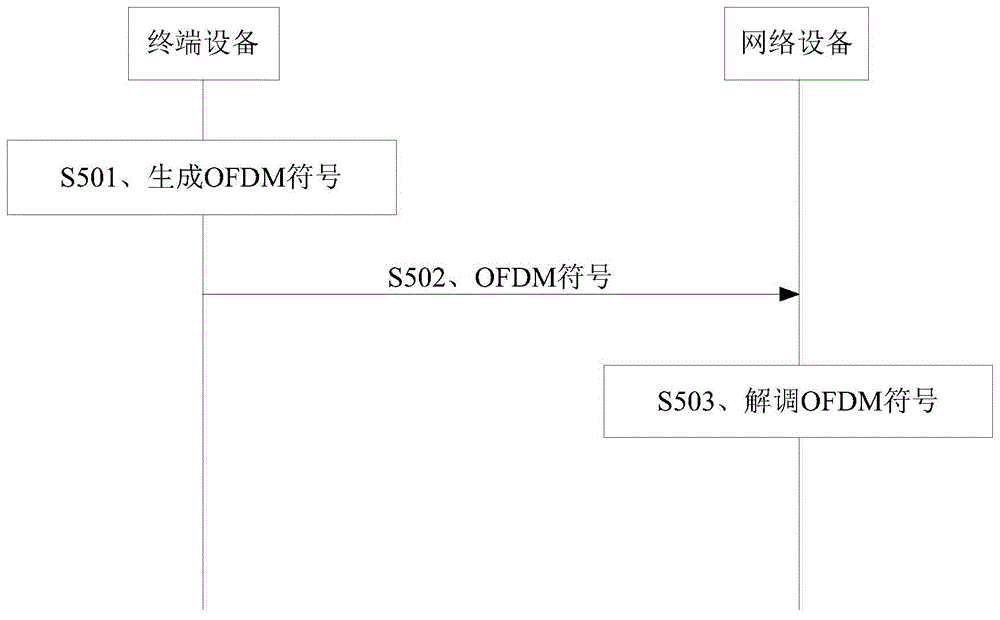
图5为本申请提供的信号接收及发送方法实施例一的交互流程图,如图5所示,该方法包括:FIG. 5 is an interaction flowchart of
S501、终端设备生成OFDM符号。S501. A terminal device generates an OFDM symbol.
S502、终端设备在第一时间单元向网络设备发送至少两个OFDM符号,以及在第二时间单元向网络设备发送至少两个OFDM符号。S502. The terminal device sends at least two OFDM symbols to the network device in the first time unit, and sends at least two OFDM symbols to the network device in the second time unit.
其中,上述第一时间单元的时长和上述第二时间单元的时长相同。Wherein, the duration of the first time unit is the same as the duration of the second time unit.
其中,上述第一时间单元内OFDM符号的相位偏移和上述第二时间单元内OFDM符号的相位偏移相等。上述第一时间内第一OFDM符号的相位偏移与第一时间内除该第一 OFDM符号之外的至少一个OFDM符号的相位偏移不相等。Wherein, the phase offset of the OFDM symbols in the first time unit is equal to the phase offset of the OFDM symbols in the second time unit. The phase offset of the first OFDM symbol within the first time period is not equal to the phase offset of at least one OFDM symbol other than the first OFDM symbol within the first time period.
S503、网络设备在第一时间单元上接收至少两个OFDM符号,以及在第二时间单元上接收至少两个OFDM符号之后,对在第一时间单元接收到的至少两个OFDM符号以及在第二时间单元接收到的至少两个OFDM符号进行解调。S503. The network device receives at least two OFDM symbols in the first time unit, and after receiving the at least two OFDM symbols in the second time unit, compares the at least two OFDM symbols received in the first time unit and the at least two OFDM symbols received in the second time unit. The at least two OFDM symbols received by the time unit are demodulated.
图6为本实施例中终端发送OFDM符号的示意图,如图6所示,以30KHz的子载波间隔为例,终端设备以30KHz的子载波间隔向网络设备发送上行信号,其中,第一时间单元和第二时间单元分别对于两个OFDM符号的时间间隔,即第一时间单元和第二时间单元的时长相同。FIG. 6 is a schematic diagram of the terminal sending OFDM symbols in this embodiment. As shown in FIG. 6, taking the subcarrier interval of 30KHz as an example, the terminal device sends an uplink signal to the network device at the subcarrier interval of 30KHz, wherein the first time unit and the second time unit respectively correspond to the time interval of two OFDM symbols, that is, the duration of the first time unit and the second time unit are the same.
以下结合图6对上述的第一时间单元内OFDM符号的相位偏移和第二时间单元内OFDM符号的相位偏移相等进行解释。The following explains that the phase offset of the OFDM symbol in the first time unit and the phase offset of the OFDM symbol in the second time unit are equal to each other with reference to FIG. 6 .
假设在第一时间单元以及第二时间单元内分别都有k个采样时间点,k为正整数。则第一时间单元内的第m个采样时间点上的相位偏移与第二时间单元内的第m个采样时间点上的相位偏移相等,其中,m可以是小于等于k的任意一个正整数。则从整体上看,第一时间单元的整体相位偏移与第二时间单元的整体相位偏移相等。It is assumed that there are k sampling time points in the first time unit and the second time unit respectively, and k is a positive integer. Then the phase offset at the mth sampling time point in the first time unit is equal to the phase offset at the mth sampling time point in the second time unit, where m can be any positive value less than or equal to k. Integer. As a whole, the overall phase offset of the first time unit is equal to the overall phase offset of the second time unit.
以下结合图6对上述的第一时间内第一OFDM符号的相位偏移与第一时间单元内除该第一OFDM符号之外的至少一个OFDM符号的相位偏移不相等进行解释。The following explains that the phase offset of the first OFDM symbol in the first time unit is not equal to the phase offset of at least one OFDM symbol other than the first OFDM symbol in the first time unit with reference to FIG. 6 .
假设在第一时间单元内有k个采样时间点,k为正整数。则对于第一时间单元内的第 m个采样时间点,其相位偏移和第一时间单元内的第n个采样时间点的相位偏移不同,其中,m和n为小于等于k的正整数,并且m和n不相等。同样的,在第二时间单元内,第m个采样时间点的相位偏移也与第n个采样时间点的相位偏移不相等。即,相位偏移的一个周期为第一时间单元对应的时长,第一时间单元内只有一个相位偏移的周期。It is assumed that there are k sampling time points in the first time unit, and k is a positive integer. Then for the mth sampling time point in the first time unit, the phase offset is different from the phase offset of the nth sampling time point in the first time unit, where m and n are positive integers less than or equal to k , and m and n are not equal. Similarly, in the second time unit, the phase offset of the mth sampling time point is also not equal to the phase offset of the nth sampling time point. That is, one cycle of the phase offset is the duration corresponding to the first time unit, and there is only one cycle of the phase offset in the first time unit.
需要说明的是,本申请可以应用于第一时间单元内的所有OFDM符号的CP长度都相等的情况,另外,对于第一时间单元内的OFDM符号的CP长度不相等的情况,假设第一时间单元内的OFDM符号L的CP为短CP,即CP长度较短,第一时间单元内的OFDM 符号M的CP为长CP,即CP长度较长,则可以将OFDM符号L分为两部分,第一部分中的采样时间点数量与OFDM符号M的采样时间点数量相等,针对该第一部分与OFDM 符号M可以采用本申请所述方案进行处理,在网络设备侧可以进行统一的相位补偿,而OFDM符号L的剩余部分可以按照现有技术单独进行相位补偿。It should be noted that the present application can be applied to the case where the CP lengths of all OFDM symbols in the first time unit are equal. In addition, for the case where the CP lengths of the OFDM symbols in the first time unit are not equal, it is assumed that the first time unit If the CP of the OFDM symbol L in the unit is a short CP, that is, the CP length is short, and the CP of the OFDM symbol M in the first time unit is a long CP, that is, the CP length is long, the OFDM symbol L can be divided into two parts, The number of sampling time points in the first part is equal to the number of sampling time points of the OFDM symbol M, and the first part and the OFDM symbol M can be processed by the solution described in this application, and unified phase compensation can be performed on the network device side, while the OFDM The remainder of the symbol L can be phase compensated individually according to the prior art.
由于本实施例中第一时间单元内OFDM符号的相位偏移和第二时间单元内OFDM符号的相位偏移相等。因此,本实施例也满足第一时间单元内的OFDM符号的CP长度不相等的情况。Because in this embodiment, the phase offset of the OFDM symbols in the first time unit is equal to the phase offset of the OFDM symbols in the second time unit. Therefore, this embodiment also satisfies the situation that the CP lengths of the OFDM symbols in the first time unit are not equal.
本实施例中,终端设备向网络设备发送上行信号的第一时间单元和第二时间单元至少包括两个OFDM符号,第一时间单元和第二时间之间的相位偏移相同,并且第一时间单元内部OFDM符号的相位偏移与其余至少一个OFDM符号的相位偏移不同,因此,相位偏移的周期相较现有的方式进行了扩展,因此,终端设备因相位偏移的周期变化而进行的处理频率降低,因此能够降低终端设备的处理复杂度。In this embodiment, the first time unit and the second time unit in which the terminal device sends the uplink signal to the network device include at least two OFDM symbols, the phase offset between the first time unit and the second time unit is the same, and the first time unit and the second time unit are the same. The phase offset of the OFDM symbol in the unit is different from the phase offset of the other at least one OFDM symbol. Therefore, the period of the phase offset is extended compared with the existing method. The processing frequency is reduced, so the processing complexity of the terminal device can be reduced.
在另一种实施例中,网络设备在第三时间单元从终端设备接收OFDM符号,并且,在第四时间单元从终端设备接收OFDM符号,其中,第三时间单元内OFDM符号的相位偏移和第四时间单元内OFDM符号的相位偏移相等,第三时间单元的时长和第四时间单元的时长相同。In another embodiment, the network device receives OFDM symbols from the terminal device in a third time unit, and receives OFDM symbols from the terminal device in a fourth time unit, wherein the phase offset of the OFDM symbols in the third time unit and The phase offsets of the OFDM symbols in the fourth time unit are equal, and the duration of the third time unit is the same as the duration of the fourth time unit.
具体地,网络设备可以在第三时间单元从一个终端设备接收OFDM符号,在第四时间单元从另一个终端设备接收OFDM符号,这两个终端设备所发送的OFDM符号分别使用不同的子载波间隔。而由于第三时间单元和第四时间单元的时长相同,并且,第三时间单元和第四时间单元的OFDM符号的相位偏移相等,因此,当网络设备在第三时间单元和第四时间单元接收到OFDM符号后,可以统一对OFDM符号进行相位补偿。Specifically, the network device may receive OFDM symbols from one terminal device in a third time unit, and receive OFDM symbols from another terminal device in a fourth time unit, and the OFDM symbols sent by the two terminal devices use different subcarrier intervals respectively. . However, since the durations of the third time unit and the fourth time unit are the same, and the phase offsets of the OFDM symbols of the third time unit and the fourth time unit are equal, therefore, when the network device is in the third time unit and the fourth time unit After the OFDM symbols are received, phase compensation can be performed uniformly on the OFDM symbols.
以下以一个具体实例来说明。A specific example is given below.
图7为本申请提供的信号接收和发送方法实施例二的示例图,如图7所示,假设网络设备同时从第一终端设备和第二终端设备接收上行信号,其中,第一终端设备的子载波间隔为15KHz,第二终端设备的子载波间隔为30KHz。第三时间单元为第一终端设备发送的1个OFDM符号的时间,第四时间单元为第二终端设备发送的2个OFDM符号的时间。其中,第一终端设备在第三时间单元的相位偏移与第二终端设备在第四时间单元的相位偏移相同。则当网络设备接收到第一终端设备和第二终端设备发送的上行信号之后,就可以统一按照第一时间单元对上行信号进行补偿。FIG. 7 is an example diagram of
本实施例中,终端设备向网络设备发送上行信号的第三时间单元和第四时间单元至少包括两个OFDM符号,第三时间单元和第四时间之间的相位偏移相同,并且第三时间单元内部OFDM符号的相位偏移与其余至少一个OFDM符号的相位偏移不同,则当使用不同子载波间隔的终端设备同时向网络设备发送上行信号时,只要各终端设备的第三时间单元的时长相同,并且第三时间单元的相位偏移相同,则网络设备即可统一对各终端设备发送的上行信号进行相位补偿,从而避免相位补偿的复杂度过高。In this embodiment, the third time unit and the fourth time unit in which the terminal device sends the uplink signal to the network device include at least two OFDM symbols, the phase offset between the third time unit and the fourth time unit is the same, and the third time unit and the fourth time unit are the same. The phase offset of the OFDM symbol in the unit is different from the phase offset of the other at least one OFDM symbol. When terminal devices using different subcarrier intervals send uplink signals to the network device at the same time, as long as the duration of the third time unit of each terminal device is are the same, and the phase offset of the third time unit is the same, the network device can uniformly perform phase compensation on the uplink signals sent by each terminal device, thereby avoiding excessive complexity of the phase compensation.
另外,在另一种可选的实施例中,网络设备在第五时间单元从第一终端设备接收OFDM符号以及从第二终端设备接收OFDM符号,其中,第一终端设备的第五时间单元内OFDM符号的相位偏移和第二终端设备的第五时间单元内OFDM符号的相位偏移相等。In addition, in another optional embodiment, the network device receives OFDM symbols from the first terminal device and receives OFDM symbols from the second terminal device in a fifth time unit, wherein the fifth time unit of the first terminal device The phase offset of the OFDM symbol is equal to the phase offset of the OFDM symbol in the fifth time unit of the second terminal device.
具体地,网络设备在同一个时间单元,即第五时间单元分别从两个终端设备接收OFDM符号,这两个终端设备所发送的OFDM符号分别使用不同的子载波间隔。而由于这两个终端设备在第五时间单元内的OFDM符号的相位偏移相等,因此,当网络设备在第五时间单元接收到这两个终端设备发送的OFDM符号后,可以统一对OFDM符号进行相位补偿。Specifically, the network device receives OFDM symbols from two terminal devices in the same time unit, that is, the fifth time unit, respectively, and the OFDM symbols sent by the two terminal devices use different subcarrier intervals respectively. However, since the phase offsets of the OFDM symbols of the two terminal devices in the fifth time unit are equal, when the network device receives the OFDM symbols sent by the two terminal devices in the fifth time unit, it can uniformly evaluate the OFDM symbols. Perform phase compensation.
在一种可选的实施方式中,当上述第一时间单元内的OFDM符号的子载波间隔为30KHz时,第一时间单元的OFDM符号的个数为2。对于第二时间单元也同样适用。In an optional implementation manner, when the subcarrier interval of the OFDM symbols in the first time unit is 30 KHz, the number of OFDM symbols in the first time unit is 2. The same applies to the second time unit.
在另一种可选的实施方式中,当上述第一时间单元内的OFDM符号的子载波间隔为60KHz时,第一时间单元的OFDM符号的个数为4。对于第二时间单元也同样适用。In another optional implementation manner, when the subcarrier interval of the OFDM symbols in the first time unit is 60 KHz, the number of OFDM symbols in the first time unit is four. The same applies to the second time unit.
另外,可选地,上述第一时间单元的时长可以为15KHz的子载波间隔所对应的一个符号长度,或者,上述第一时间单元的时长也可以为15KHz的子载波间隔所对应的一个时隙的时长,或者,上述第一时间单元的时长也可以为一个子帧的时长。以下分别进行说明。In addition, optionally, the duration of the first time unit may be a symbol length corresponding to a 15KHz subcarrier interval, or the duration of the first time unit may also be a time slot corresponding to a 15KHz subcarrier interval or, the duration of the first time unit may also be the duration of one subframe. Each of them will be described below.
1、第一时间单元的时长为15KHz的子载波间隔对应的一个符号长度1. The duration of the first time unit is a symbol length corresponding to the subcarrier interval of 15KHz
图8为第一时间单元的时长为15KHz的子载波间隔对应的一个符号长度的示例图,参照图8以及上述图7,第一时间单元对应30KHz的子载波间隔的2个符号,以及,对应60KHz的子载波间隔的4个符号。则如果网络设备同时接收15KHz的子载波间隔的上行数据以及30KHz的子载波间隔的上行数据,则可以按照该第一时间单元统一进行相位补偿。如果网络设备同时接收15KHz的子载波间隔的上行数据以及60KHz的子载波间隔的上行数据,也可以按照该第一时间单元统一进行相位补偿。以此类推,网络设备也可以统一对30KHz以及60KHz的子载波间隔的上行数据统一进行相位补偿。FIG. 8 is an example diagram of a symbol length corresponding to a subcarrier interval of 15KHz in the first time unit. Referring to FIG. 8 and the above-mentioned FIG. 7 , the first time unit corresponds to 2 symbols of the subcarrier interval of 30KHz, and corresponds to 4 symbols of 60KHz subcarrier spacing. Then, if the network device simultaneously receives the uplink data of the subcarrier interval of 15KHz and the uplink data of the subcarrier interval of 30KHz, the phase compensation can be uniformly performed according to the first time unit. If the network device simultaneously receives uplink data with a subcarrier interval of 15KHz and uplink data with a subcarrier interval of 60KHz, phase compensation may also be uniformly performed according to the first time unit. By analogy, the network device can also uniformly perform phase compensation on the uplink data with the subcarrier spacing of 30KHz and 60KHz.
2、第一时间单元的时长为15KHz的子载波间隔对应的一个时隙的时长2. The duration of the first time unit is the duration of a time slot corresponding to the 15KHz subcarrier interval
图9为第一时间单元的时长为15KHz的子载波间隔对应的一个时隙的时长的示意图,参照图9,第一时间单元的对应15KHz的子载波间隔的一个时隙,即7个OFDM符号,以及,对应30KHz的7个符号的2个时隙。如果网络设备同时接收15KHz的子载波间隔的上行数据以及30KHz的子载波间隔的上行数据,则可以按照该第一时间单元统一进行相位补偿。FIG. 9 is a schematic diagram of the duration of a time slot corresponding to a subcarrier interval of 15KHz in the first time unit. Referring to FIG. 9 , a time slot of the first time unit corresponding to a subcarrier interval of 15KHz, that is, 7 OFDM symbols , and 2 slots of 7 symbols corresponding to 30KHz. If the network device simultaneously receives uplink data with a subcarrier interval of 15KHz and uplink data with a subcarrier interval of 30KHz, phase compensation may be uniformly performed according to the first time unit.
3、第一时间单元的时长为一个子帧的时长3. The duration of the first time unit is the duration of one subframe
图10为第一时间单元的时长为一个子帧的时长的示意图,参照图10,第一时间单元的对应一个子帧,即15KHz的2个时隙,以及,对应30KHz的7个符号的4个时隙。如果网络设备同时接收15KHz的子载波间隔的上行数据以及30KHz的子载波间隔的上行数据,则可以按照该第一时间单元统一进行相位补偿。FIG. 10 is a schematic diagram showing that the duration of the first time unit is the duration of one subframe. Referring to FIG. 10 , the first time unit corresponds to one subframe, that is, two time slots of 15KHz, and four corresponding to 7 symbols of 30KHz. time slot. If the network device simultaneously receives uplink data with a subcarrier interval of 15KHz and uplink data with a subcarrier interval of 30KHz, phase compensation may be uniformly performed according to the first time unit.
在另一种可选的实施方式中,上述相位偏移具体指同一OFDM符号在采用第一子载波映射方式时在第一采样时间点上的第一时域采样值的相位与在采用第二子载波映射方式时在所述第一采样时间点上的第二时域采样值的相位的差值,其中,第二种子载波映射方式中,子载波的中心映射在与所述载波频率存在7.5KHz的频率上。In another optional implementation manner, the above-mentioned phase offset specifically refers to the difference between the phase of the first sample value in the time domain at the first sampling time point of the same OFDM symbol when the first subcarrier mapping method is adopted The difference between the phases of the second time domain sampling values at the first sampling time point in the subcarrier mapping mode, wherein, in the second subcarrier mapping mode, the center of the subcarrier is mapped at 7.5° from the carrier frequency. at the frequency of KHz.
以下结合终端设备设备生成OFDM符号时的公式来进行解释。The explanation will be given below in conjunction with the formula when the terminal equipment generates the OFDM symbol.
终端设备使用上述第一子载波映射方式时,使用如下公式(1)生成OFDM信号。When the terminal device uses the above-mentioned first subcarrier mapping method, the following formula (1) is used to generate the OFDM signal.

其中,


另外,终端设备使用上述第二子载波映射方式时,可以使用如下公式(2)生成OFDM符号。In addition, when the terminal device uses the above-mentioned second subcarrier mapping method, the following formula (2) can be used to generate the OFDM symbol.

其中,Δfshift为第二种子载波映射方式相对于第一种子载波映射方式的子载波偏移,Δφ即为由于该子载波偏移所带来的采样时间点的相位偏移。Wherein, Δf shift is the sub-carrier offset of the second sub-carrier mapping method relative to the first sub-carrier mapping method, and Δφ is the phase offset of the sampling time point caused by the sub-carrier offset.
由上述公式可知,Δφ与Δfshift以及采样时间点相关,因此,对于不同的子载波间隔,只要保证Δfshift以及采样时间点相同,即可保证相位偏移相同。因此,本申请中,可选地,可以预先将不同的子载波间隔的采样时间点设置为相同,并且,对于不同的子载波间隔使用相同的Δfshift,即可以保证相位偏移相同。具体地,Δfshift为7.5KHz。It can be known from the above formula that Δφ is related to Δf shift and sampling time point. Therefore, for different subcarrier intervals, as long as Δf shift and sampling time point are the same, the phase shift can be guaranteed to be the same. Therefore, in this application, optionally, the sampling time points of different subcarrier intervals can be set to be the same in advance, and the same Δf shift is used for different subcarrier intervals, that is, the same phase offset can be guaranteed. Specifically, Δf shift is 7.5KHz.
另外,上述公式(2)中的Δf可以通过如下表(1)来获得,其中,u为表示信号的子载波间隔的参数。In addition, Δf in the above formula (2) can be obtained from the following table (1), where u is a parameter representing the subcarrier spacing of the signal.
表1Table 1
以下为第一时间单元为不同时长下的具体公式示例。The following is an example of specific formulas when the first time unit is of different duration.
当第一时间单元为一个子帧,即相位偏移的周期为一个子帧时,OFDM符号的生成公式可以表示为下述公式(3)。When the first time unit is one subframe, that is, the period of the phase offset is one subframe, the generation formula of the OFDM symbol can be expressed as the following formula (3).

当第一时间单元为一个15KHz子载波间隔的符号长度,即相位偏移的周期为一个15KHz子载波间隔的符号长度时,OFDM符号的生成公式可以表示为下述公式(4)。When the first time unit is a symbol length of a 15KHz subcarrier interval, that is, the period of the phase offset is a symbol length of a 15KHz subcarrier interval, the generation formula of the OFDM symbol can be expressed as the following formula (4).

当第一时间单元为一个15KHz子载波间隔的时隙长度,即相位偏移的周期为1 个15KHz子载波间隔的时隙长度时,OFDM符号的生成公式可以表示为下述公式(5)。When the first time unit is a time slot length of a 15KHz subcarrier interval, that is, the period of the phase offset is a time slot length of a 15KHz subcarrier interval, the generation formula of the OFDM symbol can be expressed as the following formula (5).

其中,
需要说明的是,上述公式只是一种可能的表现形式,当然还可以采用其他形式的公式进行描述,本申请对此不做限定。It should be noted that the above formula is only a possible expression form, and of course other forms of formulas may also be used for description, which is not limited in this application.
例如,可以使用如下公式(6)表示第

当第一时间单元为一个子帧,即相位偏移的周期为一个子帧时,OFDM符号的生成公式可以表示为下述公式(7)。When the first time unit is one subframe, that is, the period of the phase offset is one subframe, the generation formula of the OFDM symbol can be expressed as the following formula (7).

当第一时间单元为一个15KHz子载波间隔的符号长度,即相位偏移的周期为一个15KHz子载波间隔的符号长度时,OFDM符号的生成公式可以表示为下述公式(8)。When the first time unit is a symbol length of a 15KHz subcarrier interval, that is, the period of the phase offset is a symbol length of a 15KHz subcarrier interval, the generation formula of the OFDM symbol can be expressed as the following formula (8).

图11为本申请提供的终端设备实施例一的模块结构图,如图11所示,该终端设备包括:FIG. 11 is a module structure diagram of
处理模块1101,用于生成OFDM符号。The
发送模块1102,用于在第一时间单元向网络设备发送至少两个OFDM符号,以及在第二时间单元向网络设备发送至少两个OFDM符号,第一时间单元内OFDM符号的相位偏移和第二时间单元内OFDM符号的相位偏移相等,并且,第一时间单元内第一OFDM 符号的相位偏移与第一时间单元内除第一OFDM符号之外的至少一个OFDM符号的相位偏移不相等,其中,第一时间单元的时长和第二时间单元的时长相同。The sending
该终端设备用于实现前述方法实施例,其实现原理和技术效果类似,此处不再赘述。The terminal device is used to implement the foregoing method embodiments, and its implementation principles and technical effects are similar, and details are not described herein again.
在一种可选的实施方式中,第一时间单元的时长为15KHz的子载波间隔所对应的一个时隙的时长。In an optional implementation manner, the duration of the first time unit is the duration of one time slot corresponding to the 15KHz subcarrier interval.
在一种可选的实施方式中,第一时间单元的时长为一个子帧的时长。In an optional implementation manner, the duration of the first time unit is the duration of one subframe.
在一种可选的实施方式中,第一时间单元的时长为15KHz的子载波间隔所对应的一个符号长度。In an optional implementation manner, the duration of the first time unit is a symbol length corresponding to a subcarrier interval of 15KHz.
在一种可选的实施方式中,在第一时间单元内的OFDM符号的子载波间隔为30KHz时,第一时间单元内的OFDM符号的个数为2。In an optional implementation manner, when the subcarrier interval of the OFDM symbols in the first time unit is 30 KHz, the number of OFDM symbols in the first time unit is 2.
在一种可选的实施方式中,在第一时间单元内的OFDM符号的子载波间隔为60KHz时,第一时间单元内的OFDM符号的个数为4。In an optional implementation manner, when the subcarrier interval of the OFDM symbols in the first time unit is 60 KHz, the number of OFDM symbols in the first time unit is 4.
在一种可选的实施方式中,上述相位偏移为同一OFDM符号在采用第一子载波映射方式时在第一采样时间点上的第一时域采样值的相位与在采用第二子载波映射方式时在第一采样时间点上的第二时域采样值的相位的差值。In an optional implementation manner, the above-mentioned phase offset is the phase of the first time domain sample value at the first sampling time point of the same OFDM symbol when the first subcarrier mapping method is adopted and the phase of the first time domain sample value at the first sampling time point when the second subcarrier mapping method is adopted. The difference between the phases of the second time domain sample values at the first sample time point in the mapping mode.
其中,在第一子载波映射方式中,子载波的中心映射在载波频率,在第二子载波映射方式中,子载波的中心映射在与载波频率存在预设偏移值的频率上。Wherein, in the first subcarrier mapping method, the center of the subcarrier is mapped on the carrier frequency, and in the second subcarrier mapping method, the center of the subcarrier is mapped on the frequency with a preset offset value from the carrier frequency.
在一种可选的实施方式中,上述预设偏移值为7.5KHz。In an optional implementation manner, the above-mentioned preset offset value is 7.5KHz.
图12为本申请提供的网络设备实施例一的模块结构图,如图12所示,该网络设备包括:FIG. 12 is a module structure diagram of
接收模块1201,用于在第一时间单元从终端设备接收至少两个OFDM符号,以及在第二时间单元接收至少两个OFDM符号,第一时间单元内OFDM符号的相位偏移和第二时间单元内OFDM符号的相位偏移相等,并且,第一时间单元内第一OFDM符号的相位偏移与第一时间单元内除第一OFDM符号之外的至少一个OFDM符号的相位偏移不相等,其中,第一时间单元的时长和第二时间单元的时长相同。A
处理模块1202,用于对在所述第一时间单元接收到的至少两个OFDM符号以及在所述第二时间单元接收到的至少两个OFDM符号进行解调。The
该网络设备用于实现前述方法实施例,其实现原理和技术效果类似,此处不再赘述。The network device is used to implement the foregoing method embodiments, and its implementation principles and technical effects are similar, and details are not described herein again.
在一种可选的实施方式中,第一时间单元的时长为15KHz的子载波间隔所对应的一个时隙的时长。In an optional implementation manner, the duration of the first time unit is the duration of one time slot corresponding to the 15KHz subcarrier interval.
在一种可选的实施方式中,第一时间单元的时长为一个子帧的时长。In an optional implementation manner, the duration of the first time unit is the duration of one subframe.
在一种可选的实施方式中,第一时间单元的时长为15KHz的子载波间隔所对应的一个符号长度。In an optional implementation manner, the duration of the first time unit is a symbol length corresponding to a subcarrier interval of 15KHz.
在一种可选的实施方式中,在第一时间单元内的OFDM符号的子载波间隔为30KHz时,第一时间单元内的OFDM符号的个数为2。In an optional implementation manner, when the subcarrier interval of the OFDM symbols in the first time unit is 30 KHz, the number of OFDM symbols in the first time unit is 2.
在一种可选的实施方式中,在第一时间单元内的OFDM符号的子载波间隔为60KHz时,第一时间单元内的OFDM符号的个数为4。In an optional implementation manner, when the subcarrier interval of the OFDM symbols in the first time unit is 60 KHz, the number of OFDM symbols in the first time unit is 4.
在一种可选的实施方式中,上述相位偏移为同一OFDM符号在采用第一子载波映射方式时在第一采样时间点上的第一时域采样值的相位与在采用第二子载波映射方式时在第一采样时间点上的第二时域采样值的相位的差值。In an optional implementation manner, the above-mentioned phase offset is the phase of the first time domain sample value at the first sampling time point of the same OFDM symbol when the first subcarrier mapping method is adopted and the phase of the first time domain sample value at the first sampling time point when the second subcarrier mapping method is adopted. The difference between the phases of the second time domain sample values at the first sample time point in the mapping mode.
其中,在第一子载波映射方式中,子载波的中心映射在载波频率,在第二子载波映射方式中,子载波的中心映射在与载波频率存在预设偏移值的频率上。Wherein, in the first subcarrier mapping method, the center of the subcarrier is mapped on the carrier frequency, and in the second subcarrier mapping method, the center of the subcarrier is mapped on the frequency with a preset offset value from the carrier frequency.
在一种可选的实施方式中,上述预设偏移值为7.5KHz。In an optional implementation manner, the above-mentioned preset offset value is 7.5KHz.
图13为本申请提供的一种芯片的实体框图,该芯片1300可以用于终端设备,如图13所示,该芯片包括:至少一个通信接口1301,至少一个处理器1302,至少一个存储器1303,其中,通信接口1301、处理器1302和存储器1303通过电路(某些情况下也可以是总线)1304互联,处理器1302调用存储器1303中存储的指令,以执行下述方法:FIG. 13 is a physical block diagram of a chip provided by this application. The
生成OFDM符号;generate OFDM symbols;
在第一时间单元向网络设备发送至少两个OFDM符号,以及在第二时间单元向网络设备发送至少两个OFDM符号,第一时间单元内OFDM符号的相位偏移和第二时间单元内OFDM符号的相位偏移相等,并且,第一时间单元内第一OFDM符号的相位偏移与第一时间单元内除第一OFDM符号之外的至少一个OFDM符号的相位偏移不相等,其中,第一时间单元的时长和第二时间单元的时长相同。At least two OFDM symbols are sent to the network device in a first time unit, and at least two OFDM symbols are sent to the network device in a second time unit, the phase offset of the OFDM symbols in the first time unit and the OFDM symbols in the second time unit and the phase offset of the first OFDM symbol in the first time unit is not equal to the phase offset of at least one OFDM symbol other than the first OFDM symbol in the first time unit, wherein the first The duration of the time unit is the same as the duration of the second time unit.
在一种可选的实施方式中,第一时间单元的时长为15KHz的子载波间隔所对应的一个时隙的时长。In an optional implementation manner, the duration of the first time unit is the duration of one time slot corresponding to the 15KHz subcarrier interval.
在一种可选的实施方式中,第一时间单元的时长为一个子帧的时长。In an optional implementation manner, the duration of the first time unit is the duration of one subframe.
在一种可选的实施方式中,第一时间单元的时长为15KHz的子载波间隔所对应的一个符号长度。In an optional implementation manner, the duration of the first time unit is a symbol length corresponding to a subcarrier interval of 15KHz.
在一种可选的实施方式中,在第一时间单元内的OFDM符号的子载波间隔为30KHz时,第一时间单元内的OFDM符号的个数为2。In an optional implementation manner, when the subcarrier interval of the OFDM symbols in the first time unit is 30 KHz, the number of OFDM symbols in the first time unit is 2.
在一种可选的实施方式中,在第一时间单元内的OFDM符号的子载波间隔为60KHz时,第一时间单元内的OFDM符号的个数为4。In an optional implementation manner, when the subcarrier interval of the OFDM symbols in the first time unit is 60 KHz, the number of OFDM symbols in the first time unit is 4.
在一种可选的实施方式中,上述相位偏移为同一OFDM符号在采用第一子载波映射方式时在第一采样时间点上的第一时域采样值的相位与在采用第二子载波映射方式时在第一采样时间点上的第二时域采样值的相位的差值。In an optional implementation manner, the above-mentioned phase offset is the phase of the first time domain sample value at the first sampling time point of the same OFDM symbol when the first subcarrier mapping method is adopted and the phase of the first time domain sample value at the first sampling time point when the second subcarrier mapping method is adopted. The difference between the phases of the second time domain sample values at the first sample time point in the mapping mode.
其中,在第一子载波映射方式中,子载波的中心映射在载波频率,在第二子载波映射方式中,子载波的中心映射在与载波频率存在预设偏移值的频率上。Wherein, in the first subcarrier mapping method, the center of the subcarrier is mapped on the carrier frequency, and in the second subcarrier mapping method, the center of the subcarrier is mapped on the frequency with a preset offset value from the carrier frequency.
在一种可选的实施方式中,上述预设偏移值为7.5KHz。In an optional implementation manner, the above-mentioned preset offset value is 7.5KHz.
图14为本申请提供的另一种芯片的实体框图,该芯片1400可以用于网络设备,如图 14所示,该芯片包括:至少一个通信接口1401,至少一个处理器1402,至少一个存储器1403,其中,通信接口1401、处理器1402和存储器1403通过电路(某些情况下也可以是总线)1404互联,处理器1402调用存储器1403中存储的指令,以执行下述方法:FIG. 14 is a physical block diagram of another chip provided by this application. The
在第一时间单元从终端设备接收至少两个OFDM符号,以及在第二时间单元接收至少两个OFDM符号,第一时间单元内OFDM符号的相位偏移和第二时间单元内OFDM符号的相位偏移相等,并且,第一时间单元内第一OFDM符号的相位偏移与第一时间单元内除第一OFDM符号之外的至少一个OFDM符号的相位偏移不相等,其中,第一时间单元的时长和第二时间单元的时长相同;At least two OFDM symbols are received from the terminal device in a first time unit, and at least two OFDM symbols are received in a second time unit, the phase offset of the OFDM symbols in the first time unit and the phase offset of the OFDM symbols in the second time unit and the phase offset of the first OFDM symbol in the first time unit is not equal to the phase offset of at least one OFDM symbol other than the first OFDM symbol in the first time unit, wherein the phase offset of the first time unit The duration is the same as the duration of the second time unit;
对在第一时间单元接收到的至少两个OFDM符号以及在第二时间单元接收到的至少两个OFDM符号进行解调。The at least two OFDM symbols received in the first time unit and the at least two OFDM symbols received in the second time unit are demodulated.
在一种可选的实施方式中,第一时间单元的时长为15KHz的子载波间隔所对应的一个时隙的时长。In an optional implementation manner, the duration of the first time unit is the duration of one time slot corresponding to the 15KHz subcarrier interval.
在一种可选的实施方式中,第一时间单元的时长为一个子帧的时长。In an optional implementation manner, the duration of the first time unit is the duration of one subframe.
在一种可选的实施方式中,第一时间单元的时长为15KHz的子载波间隔所对应的一个符号长度。In an optional implementation manner, the duration of the first time unit is a symbol length corresponding to a subcarrier interval of 15KHz.
在一种可选的实施方式中,在第一时间单元内的OFDM符号的子载波间隔为30KHz时,第一时间单元内的OFDM符号的个数为2。In an optional implementation manner, when the subcarrier interval of the OFDM symbols in the first time unit is 30 KHz, the number of OFDM symbols in the first time unit is 2.
在一种可选的实施方式中,在第一时间单元内的OFDM符号的子载波间隔为60KHz时,第一时间单元内的OFDM符号的个数为4。In an optional implementation manner, when the subcarrier interval of the OFDM symbols in the first time unit is 60 KHz, the number of OFDM symbols in the first time unit is 4.
在一种可选的实施方式中,上述相位偏移为同一OFDM符号在采用第一子载波映射方式时在第一采样时间点上的第一时域采样值的相位与在采用第二子载波映射方式时在第一采样时间点上的第二时域采样值的相位的差值。In an optional implementation manner, the above-mentioned phase offset is the phase of the first time domain sample value at the first sampling time point of the same OFDM symbol when the first subcarrier mapping method is adopted and the phase of the first time domain sample value at the first sampling time point when the second subcarrier mapping method is adopted. The difference between the phases of the second time domain sample values at the first sample time point in the mapping mode.
其中,在第一子载波映射方式中,子载波的中心映射在载波频率,在第二子载波映射方式中,子载波的中心映射在与载波频率存在预设偏移值的频率上。Wherein, in the first subcarrier mapping method, the center of the subcarrier is mapped on the carrier frequency, and in the second subcarrier mapping method, the center of the subcarrier is mapped on the frequency with a preset offset value from the carrier frequency.
在一种可选的实施方式中,上述预设偏移值为7.5KHz。In an optional implementation manner, the above-mentioned preset offset value is 7.5KHz.
图15为本申请提供的一种终端设备实施例一的实体框图,如图15所述,该终端设备包括:FIG. 15 is an entity block diagram of
存储器1501和处理器1502。
存储器1501用于存储程序指令,处理器1502用于调用存储器1501中的程序指令,实现上述方法实施例中终端设备的功能。The
图16为本申请提供的一种网络设备实施例一的实体框图,如图16所述,该网络设备包括:FIG. 16 is an entity block diagram of
存储器1601和处理器1602。
存储器1601用于存储程序指令,处理器1602用于调用存储器1601中的程序指令,实现上述方法实施例中网络设备的功能。The
除了上述实施例中所述的问题之外,在上行信号传输时,由于终端设备采用不同参考频率确定的上行信号对应的相位偏差不同,可能会出现信号干扰的问题。而在下行信号传输时,由于网络设备发送下行信号所使用的参考频率与终端设备接收所述下行信号所使用的参考频率可能不同,因此可能会出现终端设备错误接收下行信号的问题。本申请以下实施例所提供的方法可以进一步解决这些问题。In addition to the problems described in the above embodiments, during uplink signal transmission, since the phase deviations corresponding to the uplink signals determined by the terminal equipment using different reference frequencies are different, the problem of signal interference may occur. During downlink signal transmission, since the reference frequency used by the network device to send the downlink signal and the reference frequency used by the terminal device to receive the downlink signal may be different, the problem that the terminal device erroneously receives the downlink signal may occur. The methods provided in the following embodiments of the present application can further solve these problems.
图17为本申请提供的另一种信号发送及接收方法的流程示意图,该方法用于上行信号传输中,如图17所示,该方法包括:FIG. 17 is a schematic flowchart of another method for transmitting and receiving signals provided by this application. The method is used in uplink signal transmission. As shown in FIG. 17 , the method includes:
S1701、终端设备确定第一频率位置,其中,所述第一频率位置用于所述终端设备确定上行信号的参考频率。S1701. A terminal device determines a first frequency location, where the first frequency location is used by the terminal device to determine a reference frequency of an uplink signal.
S1702、终端设备根据所述参考频率向网络设备发送所述上行信号。S1702. The terminal device sends the uplink signal to the network device according to the reference frequency.
可选的,终端设备根据预先定义的规则确定第一频率位置。第一频率位置是预先定义的。作为一种示例,所述第一频率位置为编号为X的频域资源块中的编号为Y的子载波的中心频率,X,Y可以是正整数,也可以是0,此处并不限制X,Y的取值。可选的, X=0,Y=0,即所述第一频率位置为编号为0的频域资源块中的编号为0的子载波的中心频率。需要说明的是,此处的频域资源块的编号可以是频域资源块在部分带宽(bandwidth part)中的编号,也可以是在载波带宽中的编号。该载波带宽可以是终端设备工作载波的带宽,也可以是网络设备通知给终端设备的载波带宽。例如终端设备确定的网络设备的工作载波的带宽,当然还可以是其他类型的带宽,此处不做限制。此处的频域资源块的编号还可以是公共资源块中的编号。公共资源块可以是预先定义的一个或多个资源块。Optionally, the terminal device determines the first frequency position according to a predefined rule. The first frequency position is predefined. As an example, the first frequency position is the center frequency of the subcarrier numbered Y in the frequency domain resource block numbered X, and X and Y may be positive integers or 0, and X is not limited here. , the value of Y. Optionally, X=0, Y=0, that is, the first frequency position is the center frequency of the subcarrier numbered 0 in the frequency domain resource block numbered 0. It should be noted that, the number of the frequency domain resource block here may be the number of the frequency domain resource block in the part bandwidth (bandwidth part), or the number in the carrier bandwidth. The carrier bandwidth may be the bandwidth of the working carrier of the terminal device, or may be the carrier bandwidth notified to the terminal device by the network device. For example, the bandwidth of the working carrier of the network device determined by the terminal device may, of course, be other types of bandwidth, which are not limited here. The numbers of the frequency domain resource blocks here may also be the numbers in the common resource blocks. The common resource block can be one or more predefined resource blocks.
可选的,终端根据从网络设备接收的指示信息确定第一频率位置。其中,所述指示信息指示所述第一频率位置。作为一种示例,所述指示信息指示频域上的公共参考点,从而所述第一频率位置即为所述公共参考点所在的频率。所述公共参考点可以为资源块网格的参考点。例如,所述公共参考点为资源块网格的原点。根据所述公共参考点可以确定资源块的位置。另外,所述公共参考点可以为一个小区中多个终端设备共同的参考点。所述公共参考点所对应的资源块可以认为是公共资源块。可选的,所述指示信息携带在系统消息或者无线资源控制(Radio resource control,RRC)层信令中由网络设备发送给终端设备。具体的,所述指示信息可以指示公共参考点对应的绝对无线频道号(absolute radiofrequency channel number,ARFCN)。其中,ARFCN的取值可以包括0和正整数,不同的ARFCN取值对应不同的频率。例如,新空口系统中的ARFCN的取值范围为0到3279165。其中,0对应0Hz,1对应5kHz,2对应10kHz等。终端设备可以根据所述指示信息中指示的ARFCN的值确定公共参考点对应的频率。具体的,所述公共参考点可以是新空口系统中定义的参考点A(Point A)。Optionally, the terminal determines the first frequency location according to the indication information received from the network device. Wherein, the indication information indicates the first frequency position. As an example, the indication information indicates a common reference point in the frequency domain, so that the first frequency position is the frequency where the common reference point is located. The common reference point may be a reference point of a grid of resource blocks. For example, the common reference point is the origin of the resource block grid. The location of the resource block can be determined according to the common reference point. In addition, the common reference point may be a reference point common to multiple terminal devices in a cell. The resource block corresponding to the common reference point may be regarded as a common resource block. Optionally, the indication information is carried in a system message or a radio resource control (Radio resource control, RRC) layer signaling and sent by the network device to the terminal device. Specifically, the indication information may indicate an absolute radio frequency channel number (absolute radio frequency channel number, ARFCN) corresponding to the common reference point. The value of ARFCN may include 0 and a positive integer, and different ARFCN values correspond to different frequencies. For example, the value range of ARFCN in the NR system is 0 to 3279165. Among them, 0 corresponds to 0Hz, 1 corresponds to 5kHz, 2 corresponds to 10kHz, etc. The terminal device may determine the frequency corresponding to the common reference point according to the value of the ARFCN indicated in the indication information. Specifically, the common reference point may be a reference point A (Point A) defined in a new air interface system.
可选地,所述公共参考点所在的频率为所述上行信号对应的上行基带信号的调制频率。这里的调制频率可以是对上行基带信号进行上变频或其他处理(例如调制或对信号进行频率搬移)所使用的频率。Optionally, the frequency at which the common reference point is located is the modulation frequency of the uplink baseband signal corresponding to the uplink signal. The modulation frequency here may be the frequency used for up-conversion or other processing (eg, modulation or frequency shifting of the signal) for the uplink baseband signal.
作为一种示例,所述指示信息可以指示编号为X的频域资源块中的编号为Y的子载波,或者指示编号为X的频域资源块中的编号为Y的子载波的中心频率。X,Y可以是正整数,也可以是0,此处并不限制X,Y的取值。可选的,所述指示信息只能指示编号为X的频域资源块中的编号为0的子载波,或者编号为6的子载波,或者编号为0或6 的子载波。这样可以减少该指示信息所需的比特数,降低指示开销。As an example, the indication information may indicate the subcarrier numbered Y in the frequency domain resource block numbered X, or the center frequency of the subcarrier numbered Y in the frequency domain resource block numbered X. X and Y can be positive integers or 0, and the values of X and Y are not limited here. Optionally, the indication information can only indicate the subcarrier numbered 0 in the frequency domain resource block numbered X, or the subcarrier numbered 6, or the subcarrier numbered 0 or 6. In this way, the number of bits required for the indication information can be reduced, and the indication overhead can be reduced.
作为另一种示例,所述指示信息可以仅指示编号为X的频域资源块,终端设备根据预先定义的规则确定编号为Y的子载波,例如,Y取值固定为0,或固定为6,或者为其他值。通过这种方式,可以减少信令开销。As another example, the indication information may only indicate the frequency domain resource block numbered X, and the terminal device determines the subcarrier numbered Y according to a predefined rule, for example, the value of Y is fixed to 0, or fixed to 6 , or another value. In this way, signaling overhead can be reduced.
作为另一种示例,所述指示信息间接的指示第一频率位置。例如,所述指示信息指示一个偏移值,该偏移值为所述第一频率位置相对于第二频率位置的偏移,所述第二频率位置为预先定义的位置,例如,所述第二频率位置为编号为X的频域资源块中的编号为Y 的子载波的中心频率。X,Y可以是正整数,也可以是0,此处并不限制X,Y的取值。可选的,X=0,Y=0,即所述第一频率位置为编号为0的频域资源块中的编号为0的子载波的中心频率。所述偏移值可以是以子载波为单位,也可以是以资源块为单位,还可以是以频率为单位。例如,所述第二频率位置对应的频率为f1,在所述指示信息指示的偏移为 N1个子载波的情况下,该子载波对应的子载波间隔为u,则所述第一频率位置对应的频率为f0=f1+N1×u,也可以为f0=f1-N1×u。又例如,所述第二频率位置对应的频率为f1,在所述指示信息指示的偏移为N2个资源块的情况下,该子载波对应的子载波间隔为u,则所述第一频率位置对应的频率为f0=f1+N2×12×u,也可以为f0=f1+N2×12×u-u。需要说明的是,上述“12”为一个资源块中的子载波个数的具体示例,根据不同的网络类型,该值也可以替换为其他值,例如:24。作为一种示例,所述第二频率位置对应的频率为f1,在所述指示信息指示的偏移为f2的情况下,则所述第一频率位置对应的频率为f0=f1+f2,也可以为f0=f1-f2。上述只为举例,并不对方法进行限定。例如,所述第一参考频率为射频参考频率。其中,该射频参考频率可以为射频带宽的中心频率。所述第二参考频率为公共参考点所在的频率,如上述参考点A。As another example, the indication information indirectly indicates the first frequency position. For example, the indication information indicates an offset value, the offset value is an offset of the first frequency position relative to a second frequency position, and the second frequency position is a predefined position, for example, the first frequency position The second frequency position is the center frequency of the subcarrier numbered Y in the frequency domain resource block numbered X. X and Y can be positive integers or 0, and the values of X and Y are not limited here. Optionally, X=0, Y=0, that is, the first frequency position is the center frequency of the subcarrier numbered 0 in the frequency domain resource block numbered 0. The offset value may be in the unit of subcarrier, may be in the unit of resource block, or may be in the unit of frequency. For example, the frequency corresponding to the second frequency position is f1, and when the offset indicated by the indication information is N1 subcarriers, and the subcarrier interval corresponding to the subcarrier is u, then the first frequency position corresponds to The frequency is f0=f1+N1×u, or it can be f0=f1-N1×u. For another example, the frequency corresponding to the second frequency position is f1, and when the offset indicated by the indication information is N2 resource blocks, and the subcarrier interval corresponding to the subcarrier is u, then the first frequency The frequency corresponding to the position is f0=f1+N2×12×u, or f0=f1+N2×12×u-u. It should be noted that the above "12" is a specific example of the number of subcarriers in a resource block. According to different network types, this value can also be replaced with other values, for example: 24. As an example, the frequency corresponding to the second frequency position is f1, and if the offset indicated by the indication information is f2, the frequency corresponding to the first frequency position is f0=f1+f2, and It can be f0=f1-f2. The above is only an example, and does not limit the method. For example, the first reference frequency is a radio frequency reference frequency. Wherein, the radio frequency reference frequency may be the center frequency of the radio frequency bandwidth. The second reference frequency is the frequency where the common reference point is located, such as the reference point A above.
可选的,所述上行信号包括上行数据信号,上行控制信号,上行接入信号或者上行参考信号中的至少一种。上行数据信号可以是物理上行共享信道或者相同功能名称不同的信号,上行控制信号可以是物理上行控制信道或者功能相同名称不同的信号,上行接入信号可以是物理随机接入信号或者相同功能名称不同的信号,上行参考信号可以是解调参考信号,探测参考信号等。Optionally, the uplink signal includes at least one of an uplink data signal, an uplink control signal, an uplink access signal or an uplink reference signal. The uplink data signal can be a physical uplink shared channel or a signal with the same function with different names, the uplink control signal can be a physical uplink control channel or a signal with the same function and a different name, and the uplink access signal can be a physical random access signal or the same function with a different name. The uplink reference signal may be a demodulation reference signal, a sounding reference signal, or the like.
可选的,所述终端设备可以确定所述第一频率位置对应的频率为所述参考频率,也可以根据所述第一频率位置和第一资源块个数确定所述参考频率。其中,所述第一资源块个数可以是所述终端设备预先确定的,也可以是所述网络设备通知的,此处不做限定。例如,所述第一频率位置为f1,所述第一资源块个数为N,所述第一资源块个数对应子载波间隔为u,则所述参考频率f0可以是f0=f1+N/2×12×u,也可以是f0=f1+N/2×12×u-u,当然也可以是其他值,此处不做限定。Optionally, the terminal device may determine the frequency corresponding to the first frequency position as the reference frequency, or may determine the reference frequency according to the first frequency position and the number of first resource blocks. The number of the first resource blocks may be predetermined by the terminal device or notified by the network device, which is not limited here. For example, the first frequency position is f1, the number of the first resource blocks is N, and the subcarrier spacing corresponding to the number of the first resource blocks is u, then the reference frequency f0 may be f0=f1+N /2×12×u, may also be f0=f1+N/2×12×u−u, and of course may be other values, which are not limited here.
可选的,所述参考频率可以是终端设备射频带宽的中心频率,也可以是直流子载波的中心频率。其中,直流子载波可以理解为基带信号中频率为0的子载波,所述参考频率还可以是终端设备生成OFDM信号的中心频率,当然也可以是其他频率。Optionally, the reference frequency may be the center frequency of the radio frequency bandwidth of the terminal device, or may be the center frequency of the DC subcarrier. The DC sub-carrier may be understood as a sub-carrier with a frequency of 0 in the baseband signal, and the reference frequency may also be the center frequency of the OFDM signal generated by the terminal device, and certainly may be other frequencies.
具体的,所述参考频率还可以是射频参考频率。作为一种示例,所述射频参考频率与所述终端设备的中心子载波所在频率位置相同,所述中心子载波可以是载波带宽的中心子载波。关于中心子载波的理解可以为:载波带宽中有Z个频域资源块,编号从0到Z-1,每个频域资源块中有n个子载波,子载波在每个频域资源块中的编号从0到n-1,则载波带宽中总共有Z×n个子载波,编号可以从0到Z×n-1,则该载波带宽的中心子载波即为编号为Z×n/2的子载波或者为编号为(Z×n-1)/2的子载波。例如,载波带宽中有11个频域资源块时,编号从0到10,每个频域资源块中有12个子载波,编号从0到11,则该载波带宽的中心子载波为编号为5的频域资源块中编号为6的子载波,又可以为该11个频域资源块中编号为66的子载波。又例如,载波带宽中有12个频域资源块,编号从0到11,每个频域资源块中有12个子载波,编号从0到11,则该载波带宽的中心子载波为编号为 6的频域资源块中编号为0的子载波,又可以为该12个频域资源块中编号为72的子载波。该载波带宽中的频域资源块个数Z可以是预先规定的值,例如是协议中规定的对应于该载波带宽的资源块个数最大值,也可以是网络设备确定的值,还可以是网络设备通知给终端设备的值,此处不做限定。需要说明的是,当该载波带宽中只配置了第一子载波间隔时,第一子载波间隔可以15kHz或30kHz或其他值,所述射频参考频率为第一子载波间隔对应的频域资源块的中心子载波所在的频率。当该载波带宽中配置了多于一个子载波间隔时,所述射频参考频率为所述多于一个子载波间隔中最小的子载波间隔对应的频域资源块的中心子载波所在的频率。例如,当载波带宽中配置了15kHz和30kHz两种子载波间隔时,射频参考频率为15kHz对应的频域资源块的中心子载波所在的频率。当该载波带宽中配置了多于一个子载波间隔时,所述射频参考频率为所述多于一个子载波间隔中的目标子载波间隔对应的频域资源块的中心子载波所在的频率。所述目标子载波间隔为网络设备向终端设备通知的子载波间隔。所述目标子载波间隔为所述网络设备为终端配置的用于确定所述射频参考频率的子载波间隔。例如,当载波带宽中配置了15kHz和30kHz两种子载波间隔时,网络设备可以向终端设备通知的目标子载波间隔可以是15kHz也可以是30kHz,则终端设备根据通知的目标子载波间隔确定所述射频参考频率。Specifically, the reference frequency may also be a radio frequency reference frequency. As an example, the radio frequency reference frequency is at the same frequency position as the center subcarrier of the terminal device, and the center subcarrier may be the center subcarrier of the carrier bandwidth. The understanding of the central subcarrier can be as follows: There are Z frequency domain resource blocks in the carrier bandwidth, numbered from 0 to Z-1, there are n subcarriers in each frequency domain resource block, and the subcarriers are in each frequency domain resource block. numbered from 0 to n-1, there are Z×n subcarriers in the carrier bandwidth, and the numbers can be from 0 to Z×n-1, then the center subcarrier of the carrier bandwidth is the subcarrier numbered Z×n/2 The subcarriers are either subcarriers numbered (Z×n-1)/2. For example, when there are 11 frequency domain resource blocks in the carrier bandwidth, numbered from 0 to 10, and each frequency domain resource block has 12 subcarriers, numbered from 0 to 11, the center subcarrier of the carrier bandwidth is numbered 5 The subcarrier numbered 6 in the frequency-domain resource block of , may also be the subcarrier numbered 66 in the 11 frequency-domain resource blocks. For another example, there are 12 frequency domain resource blocks in the carrier bandwidth, numbered from 0 to 11, and each frequency domain resource block has 12 subcarriers, numbered from 0 to 11, then the center subcarrier of the carrier bandwidth is numbered 6 The subcarrier numbered 0 in the frequency domain resource block of 12 can be the subcarrier numbered 72 in the 12 frequency domain resource blocks. The number Z of frequency domain resource blocks in the carrier bandwidth may be a predetermined value, such as the maximum number of resource blocks corresponding to the carrier bandwidth specified in the protocol, or a value determined by the network device, or The value notified by the network device to the terminal device is not limited here. It should be noted that when only the first subcarrier spacing is configured in the carrier bandwidth, the first subcarrier spacing may be 15 kHz or 30 kHz or other values, and the radio frequency reference frequency is the frequency domain resource block corresponding to the first subcarrier spacing. The frequency at which the center subcarrier is located. When more than one subcarrier spacing is configured in the carrier bandwidth, the radio frequency reference frequency is the frequency where the center subcarrier of the frequency domain resource block corresponding to the smallest subcarrier spacing among the more than one subcarrier spacings is located. For example, when two subcarrier spacings of 15kHz and 30kHz are configured in the carrier bandwidth, the radio frequency reference frequency is the frequency where the center subcarrier of the frequency domain resource block corresponding to 15kHz is located. When more than one subcarrier interval is configured in the carrier bandwidth, the radio frequency reference frequency is the frequency where the center subcarrier of the frequency domain resource block corresponding to the target subcarrier interval in the more than one subcarrier interval is located. The target subcarrier interval is the subcarrier interval notified by the network device to the terminal device. The target subcarrier interval is a subcarrier interval configured by the network device for the terminal and used for determining the radio frequency reference frequency. For example, when two subcarrier intervals of 15kHz and 30kHz are configured in the carrier bandwidth, the target subcarrier interval notified by the network device to the terminal device may be 15kHz or 30kHz, and the terminal device determines the target subcarrier interval according to the notified target subcarrier interval. RF reference frequency.
可选的,所述终端设备可以根据所述参考频率确定上行基带信号。例如,所述终端设备可以根据所述参考频率确定上行基带信号的相位或者相位偏差。然后,所述终端设备根据所述上行基带信号再确定所述上行信号。Optionally, the terminal device may determine the uplink baseband signal according to the reference frequency. For example, the terminal device may determine the phase or phase deviation of the uplink baseband signal according to the reference frequency. Then, the terminal device re-determines the uplink signal according to the uplink baseband signal.
可选地,所述上行基带信号的相位为根据所述第一频率与所述终端设备的部分带宽的中心确定。例如上行基带信号


可选的,所述终端设备不根据所述参考频率确定上行基带信号,再根据所述参考频率将所述上行基带信号进行上变频,从而确定所述上行信号。作为一种示例,终端设备根据如下公式中的一个确定上行基带信号:
或or


其中,


或or

或or

其中,X可以是与
进一步可选的,终端设备根据如下公式将

其中,f0为参考频率。Among them, f 0 is the reference frequency.
可选的,当所述上行信号为随机接入信号时,终端设备根据如下公式确定所述随机接入信号:Optionally, when the uplink signal is a random access signal, the terminal device determines the random access signal according to the following formula:

K=Δf/ΔfRA K=Δf/Δf RA

其中,


需要说明的是,上述公式的形式可以进行变换,只要是与上述公式等价的公式都属于本发明保护的范围。It should be noted that the form of the above formula can be transformed, as long as the formula is equivalent to the above formula, it belongs to the protection scope of the present invention.
本实施例中,因为终端设备采用不同参考频率确定的上行信号对应的相位偏差会不同,这将导致空分复用的多个终端设备的信号(例如:参考信号)之间出现干扰,从而导致性能损失。本实施例方法能够使得不同终端设备采用相同的参考频率发送上行信号,从而保证这些终端设备在进行空分复用时,参考信号之间能够保持正交,避免性能损失。In this embodiment, because the phase deviations corresponding to the uplink signals determined by the terminal equipment using different reference frequencies will be different, this will cause interference between the signals (for example, reference signals) of multiple terminal equipments in space division multiplexing, thereby causing performance loss. The method in this embodiment can enable different terminal devices to send uplink signals using the same reference frequency, thereby ensuring that when these terminal devices perform space division multiplexing, the reference signals can be kept orthogonal to avoid performance loss.
图18为本申请提供的又一种信号发送及接收方法的流程示意图,该方法用于下行信号传输中,如图18所示,该方法包括:FIG. 18 is a schematic flowchart of another method for sending and receiving signals provided by this application. The method is used in downlink signal transmission. As shown in FIG. 18 , the method includes:
S1801、网络设备确定下行信号,其中,所述下行信号为根据第一频率确定的。S1801. The network device determines a downlink signal, where the downlink signal is determined according to a first frequency.
S1802、网络设备向终端设备发送所述下行信号。S1802. The network device sends the downlink signal to the terminal device.
可选的,所述网络设备向所述终端设备发送指示信息,所述指示信息指示所述第一频率。Optionally, the network device sends indication information to the terminal device, where the indication information indicates the first frequency.
可选的,所述第一频率为载波频率。Optionally, the first frequency is a carrier frequency.
可选的,所述下行信号为所述网络设备将下行基带信号上变频到所述载波频率所得到的信号。例如,所述下行基带信号为


或or

或or

其中,


或or

或or

其中,X可以是与


其中,f0为参考频率。Among them, f0 is the reference frequency.
需要说明的是,上述公式的形式可以进行变换,只要是与上述公式等价的公式都属于本发明保护的范围。It should be noted that the form of the above formula can be transformed, as long as the formula is equivalent to the above formula, it belongs to the protection scope of the present invention.
可选的,所述下行基带信号为根据所述第一频率确定的,具体的,所述下行基带信号的相位为根据所述第一频率确定的。影响所述下行基带信号的因素除了所述第一频率外还有其他因素,例如子载波间隔,带宽等,本申请在此不一一举出。Optionally, the downlink baseband signal is determined according to the first frequency, and specifically, the phase of the downlink baseband signal is determined according to the first frequency. In addition to the first frequency, there are other factors affecting the downlink baseband signal, such as subcarrier spacing, bandwidth, etc., which are not listed here in this application.
可选的,所述下行基带信号为根据所述终端设备的部分带宽的中心频率位置确定的,具体的,所述下行基带信号的相位根据所述终端设备的部分带宽的中心频率位置确定的。Optionally, the downlink baseband signal is determined according to the position of the center frequency of the partial bandwidth of the terminal equipment, and specifically, the phase of the downlink baseband signal is determined according to the position of the center frequency of the partial bandwidth of the terminal equipment.
可选的,所述下行基带信号的相位为根据所述第一频率与所述终端设备的部分带宽的中心确定。例如下行基带信号

可选的,所述下行基带信号的相位为根据所述第一频率与所述终端设备的部分带宽的中心频率的差确定的。例如,下行基带信号

S1803、终端设备确定第一频率位置,其中,所述第一频率位置用于所述终端设备确定下行信号的参考频率。S1803. The terminal device determines a first frequency position, where the first frequency position is used for the terminal device to determine a reference frequency of a downlink signal.
S1804、终端设备根据所述参考频率从网络设备接收所述下行信号。S1804. The terminal device receives the downlink signal from the network device according to the reference frequency.
可选地,本实施例还包括S1805、终端设备对所述下行信号进行解调。Optionally, this embodiment further includes S1805. The terminal device demodulates the downlink signal.
可选的,终端设备根据预先定义的规则确定第一频率位置。作为一种示例,所述第一频率位置为编号为X的频域资源块中的编号为Y的子载波的中心频率,X,Y可以是正整数,也可以是0,此处并不限制X,Y的取值。可选的,X=0,Y=0,即所述第一频率位置为编号为0的频域资源块中的编号为0的子载波的中心频率。需要说明的是,此处的频域资源块的编号可以是频域资源块在部分带宽(bandwidth part)中的编号,也可以是在载波带宽中的编号,该载波带宽可以是终端设备工作载波的带宽,也可以是网络设备通知给终端设备的载波带宽,例如终端设备确定的网络设备的工作载波的带宽,当然还可以是其他类型的带宽,此处不做限制。此处的频域资源块的编号还可以是公共资源块中的编号。公共资源块可以是预先定义的一个或多个资源块。Optionally, the terminal device determines the first frequency position according to a predefined rule. As an example, the first frequency position is the center frequency of the subcarrier numbered Y in the frequency domain resource block numbered X, and X and Y may be positive integers or 0, and X is not limited here. , the value of Y. Optionally, X=0, Y=0, that is, the first frequency position is the center frequency of the subcarrier numbered 0 in the frequency domain resource block numbered 0. It should be noted that the number of the frequency domain resource block here may be the number of the frequency domain resource block in the bandwidth part, or the number in the carrier bandwidth, and the carrier bandwidth may be the working carrier of the terminal equipment. It can also be the carrier bandwidth notified by the network device to the terminal device, such as the bandwidth of the working carrier of the network device determined by the terminal device, or other types of bandwidth, which are not limited here. The numbers of the frequency domain resource blocks here may also be the numbers in the common resource blocks. The common resource block can be one or more predefined resource blocks.
可选的,终端根据从网络设备接收的指示信息确定第一频率位置,其中,所述指示信息指示所述第一频率位置。作为一种示例,所述指示信息指示频域上的公共参考点,从而所述第一频率位置即为所述公共参考点所在的频率。所述公共参考点可以为资源块网格的参考点。例如,所述公共参考点为资源块网格的原点。根据所述公共参考点可以确定资源块的位置。另外,所述公共参考点可以为一个小区中多个终端设备共同的参考点。所述公共参考点所对应的资源块可以认为是公共资源块。可选的,所述指示信息携带在系统消息或者无线资源控制(Radio resource control,RRC)层信令中由网络设备发送给终端设备。具体的,所述指示信息可以指示公共参考点对应的ARFCN。其中,ARFCN的取值可以包括0和正整数,不同的ARFCN取值对应不同的频率。例如,新空口系统中的ARFCN 的取值范围为0到3279165。其中,0对应0Hz,1对应5kHz,2对应10kHz等。终端设备可以根据所述指示信息中指示的ARFCN的值确定公共参考点对应的频率。具体的,所述公共参考点可以是新空口系统中定义的参考点A(Point A)。参考点A可以认为是资源块网格的公共参考点。Optionally, the terminal determines the first frequency location according to indication information received from the network device, where the indication information indicates the first frequency location. As an example, the indication information indicates a common reference point in the frequency domain, so that the first frequency position is the frequency where the common reference point is located. The common reference point may be a reference point of a grid of resource blocks. For example, the common reference point is the origin of the resource block grid. The location of the resource block can be determined according to the common reference point. In addition, the common reference point may be a reference point common to multiple terminal devices in a cell. The resource block corresponding to the common reference point may be regarded as a common resource block. Optionally, the indication information is carried in a system message or a radio resource control (Radio resource control, RRC) layer signaling and sent by the network device to the terminal device. Specifically, the indication information may indicate the ARFCN corresponding to the common reference point. The value of ARFCN may include 0 and a positive integer, and different ARFCN values correspond to different frequencies. For example, the value range of ARFCN in the NR system is 0 to 3279165. Among them, 0 corresponds to 0Hz, 1 corresponds to 5kHz, 2 corresponds to 10kHz, etc. The terminal device may determine the frequency corresponding to the common reference point according to the value of the ARFCN indicated in the indication information. Specifically, the common reference point may be a reference point A (Point A) defined in a new air interface system. Reference point A can be considered as a common reference point for the resource block grid.
作为一种示例,所述指示信息可以指示编号为X的频域资源块中的编号为Y的子载波,或者指示编号为X的频域资源块中的编号为Y的子载波的中心频率,X,Y可以是正整数,也可以是0,此处并不限制X,Y的取值。可选的,所述指示信息只能指示编号为X的频域资源块中的编号为0的子载波,或者编号为6的子载波,或者编号为0或6 的子载波,这样可以减少该指示信息所需的比特数,降低指示开销。As an example, the indication information may indicate the subcarrier numbered Y in the frequency domain resource block numbered X, or the center frequency of the subcarrier numbered Y in the frequency domain resource block numbered X, X and Y can be positive integers or 0, and the values of X and Y are not limited here. Optionally, the indication information can only indicate the subcarrier numbered 0 in the frequency domain resource block numbered X, or the subcarrier numbered 6, or the subcarrier numbered 0 or 6, which can reduce the number of subcarriers. The number of bits required for the indication information reduces the indication overhead.
作为另一种示例,所述指示信息可以仅指示编号为X的频域资源块,终端设备根据预先定义的规则确定编号为Y的子载波,例如,Y取值固定为0,或固定为6,或者为其他值。通过这种方式,可以减少信令开销。As another example, the indication information may only indicate the frequency domain resource block numbered X, and the terminal device determines the subcarrier numbered Y according to a predefined rule, for example, the value of Y is fixed to 0, or fixed to 6 , or another value. In this way, signaling overhead can be reduced.
作为另一种示例,所述指示信息间接的指示第一频率位置,例如,所述指示信息指示一个偏移值,该偏移值为所述第一频率位置相对于第二频率位置的偏移,所述第二频率位置为预先定义的位置,例如,所述第二频率位置为编号为X的频域资源块中的编号为Y 的子载波的中心频率,X,Y可以是正整数,也可以是0,此处并不限制X,Y的取值。可选的,X=0,Y=0,即所述第一频率位置为编号为0的频域资源块中的编号为0的子载波的中心频率。所述偏移值可以是以子载波为单位,也可以是以资源块为单位,还可以是以频率为单位。例如,所述第二频率位置对应的频率为f1,在所述指示信息指示的偏移为 N1个子载波的情况下,该子载波对应的子载波间隔为u,则所述第一频率位置对应的频率为f0=f1+N1×u,也可以为f0=f1-N1×u。又例如,所述第二频率位置对应的频率为f1,在所述指示信息指示的偏移为N2个资源块的情况下,该子载波对应的子载波间隔为u,则所述第一频率位置对应的频率为f0=f1+N2/2×12×u,也可以为f0=f1+N2/2×12×u-u。需要说明的是,上述“12”为一个资源块中的子载波个数的具体示例,根据不同的网络类型,该值也可以替换为其他值。作为一种示例,所述第二频率位置对应的频率为f1,在所述指示信息指示的偏移为f2赫兹的情况下,则所述第一频率位置对应的频率为f0=f1+f2,也可以为f0=f1-f2。上述只为举例,并不对方法进行限定。例如,所述第一参考频率为射频参考频率。其中,该射频参考频率可以为射频带宽的中心频率。所述第二参考频率为公共参考点所在的频率,如上述参考点A。As another example, the indication information indirectly indicates the first frequency position, for example, the indication information indicates an offset value, and the offset value is an offset of the first frequency position relative to the second frequency position , the second frequency location is a predefined location, for example, the second frequency location is the center frequency of the subcarrier numbered Y in the frequency domain resource block numbered X, X, Y can be positive integers, or It can be 0, and the values of X and Y are not limited here. Optionally, X=0, Y=0, that is, the first frequency position is the center frequency of the subcarrier numbered 0 in the frequency domain resource block numbered 0. The offset value may be in the unit of subcarrier, may be in the unit of resource block, or may be in the unit of frequency. For example, the frequency corresponding to the second frequency position is f1, and when the offset indicated by the indication information is N1 subcarriers, and the subcarrier interval corresponding to the subcarrier is u, then the first frequency position corresponds to The frequency is f0=f1+N1×u, or it can be f0=f1-N1×u. For another example, the frequency corresponding to the second frequency position is f1, and when the offset indicated by the indication information is N2 resource blocks, and the subcarrier interval corresponding to the subcarrier is u, then the first frequency The frequency corresponding to the position is f0=f1+N2/2×12×u, or f0=f1+N2/2×12×u-u. It should be noted that the above "12" is a specific example of the number of subcarriers in one resource block, and this value can also be replaced with other values according to different network types. As an example, the frequency corresponding to the second frequency position is f1, and if the offset indicated by the indication information is f2 Hz, the frequency corresponding to the first frequency position is f0=f1+f2, It may also be f0=f1-f2. The above is only an example, and does not limit the method. For example, the first reference frequency is a radio frequency reference frequency. Wherein, the radio frequency reference frequency may be the center frequency of the radio frequency bandwidth. The second reference frequency is the frequency where the common reference point is located, such as the reference point A above.
可选的,所述上行信号包括上行数据信号,上行控制信号,上行接入信号或者上行参考信号中的至少一种。上行数据信号可以是物理上行共享信道或者相同功能名称不同的信号,上行控制信号可以是物理上行控制信道或者功能相同名称不同的信号,上行接入信号可以是物理随机接入信号或者相同功能名称不同的信号,上行参考信号可以是解调参考信号,探测参考信号等。Optionally, the uplink signal includes at least one of an uplink data signal, an uplink control signal, an uplink access signal or an uplink reference signal. The uplink data signal can be a physical uplink shared channel or a signal with the same function with different names, the uplink control signal can be a physical uplink control channel or a signal with the same function and a different name, and the uplink access signal can be a physical random access signal or the same function with a different name. The uplink reference signal may be a demodulation reference signal, a sounding reference signal, or the like.
可选的,所述终端设备可以直接确定所述第一频率位置对应的频率为所述参考频率,也可以根据所述第一频率位置和第一资源块个数确定所述参考频率,其中,所述第一资源块个数可以是所述终端设备预先确定的,也可以是所述网络设备通知的,此处不做限定。例如,所述第一频率位置为f1,所述第一资源块个数为N,所述第一资源块个数对应子载波间隔为u,则所述参考频率f0可以是f0=f1+N/2×12×u,也可以是f0=f1+N/2×12×u-u,当然也可以是其他值,此处不做限定。Optionally, the terminal device may directly determine the frequency corresponding to the first frequency position as the reference frequency, or may determine the reference frequency according to the first frequency position and the number of first resource blocks, wherein, The number of the first resource blocks may be predetermined by the terminal device or notified by the network device, which is not limited here. For example, the first frequency position is f1, the number of the first resource blocks is N, and the subcarrier spacing corresponding to the number of the first resource blocks is u, then the reference frequency f0 may be f0=f1+N /2×12×u, may also be f0=f1+N/2×12×u−u, and of course may be other values, which are not limited here.
可选的,所述下行信号包括下行数据信号,下行控制信号,下行参考信号,同步信号或者广播信号中的至少一种。下行数据信号可以是物理下行共享信道或者相同功能名称不同的信号,下行控制信号可以是物理下行控制信道或者功能相同名称不同的信号,上行接入信号可以是物理随机接入信号或者相同功能名称不同的信号,下行参考信号可以是解调参考信号,信道状态信息参考信号等。Optionally, the downlink signal includes at least one of a downlink data signal, a downlink control signal, a downlink reference signal, a synchronization signal or a broadcast signal. The downlink data signal can be a physical downlink shared channel or a signal with the same function with different names, the downlink control signal can be a physical downlink control channel or a signal with the same function and a different name, and the uplink access signal can be a physical random access signal or the same function with a different name. The downlink reference signal may be a demodulation reference signal, a channel state information reference signal, or the like.
可选的,所述参考频率可以是终端设备射频带宽的中心频率,也可以是直流子载波的中心频率,其中,直流子载波可以理解为基带信号中频率为0的子载波,所述参考频率还可以是终端设备从网络设备接收OFDM信号的中心频率,当然也可以是其他频率。Optionally, the reference frequency may be the center frequency of the radio frequency bandwidth of the terminal device, or the center frequency of the DC sub-carrier, where the DC sub-carrier can be understood as a sub-carrier with a frequency of 0 in the baseband signal, and the reference frequency It may also be the center frequency at which the terminal device receives the OFDM signal from the network device, and certainly may be other frequencies.
具体的,所述参考频率还可以是射频参考频率。作为一种示例,所述射频参考频率与所述终端设备的中心子载波所在频率位置相同,所述中心子载波可以是载波带宽的中心子载波。关于中心子载波的理解可以为:载波带宽中有Z个频域资源块,编号从0到Z-1,每个频域资源块中有n个子载波,子载波在每个频域资源块中的编号从0到n-1,则载波带宽中总共有Z×n个子载波,编号可以从0到Z×n-1,则该载波带宽的中心子载波即为编号为Z×n/2的子载波或者为编号为(Z×n-1)/2的子载波。例如,载波带宽中有11个频域资源块时,编号从0到10,每个频域资源块中有12个子载波,编号从0到11,则该载波带宽的中心子载波为编号为5的频域资源块中编号为6的子载波,又可以为该11个频域资源块中编号为66的子载波。又例如,载波带宽中有12个频域资源块,编号从0到11,每个频域资源块中有12个子载波,编号从0到11,则该载波带宽的中心子载波为编号为 6的频域资源块中编号为0的子载波,又可以为该12个频域资源块中编号为72的子载波。该载波带宽中的频域资源块个数Z可以是预先规定的值,例如是协议中规定的对应于该载波带宽的资源块个数最大值,也可以是网络设备确定的值,还可以是网络设备通知给终端设备的值,此处不做限定。需要说明的是,当该载波带宽中只配置了第一子载波间隔时,第一子载波间隔可以15kHz或30kHz或其他值,所述射频参考频率为第一子载波间隔对应的频域资源块的中心子载波所在的频率。当该载波带宽中配置了多于一个子载波间隔时,所述射频参考频率为所述多于一个子载波间隔中最小的子载波间隔对应的频率资源块的中心子载波所在的频率。例如,当载波带宽中配置了15kHz和30kHz两种子载波间隔时,射频参考频率为15kHz对应的频域资源块的中心子载波所在的频率。当该载波带宽中配置了多于一个子载波间隔时,所述射频参考频率为所述多于一个子载波间隔中的目标子载波间隔对应的频域资源块的中心子载波所在的频率,所述目标子载波间隔为网络设备向终端设备通知的子载波间隔。所述目标子载波间隔为所述网络设备为终端配置的用于确定所述射频参考频率的子载波间隔。例如,当载波带宽中配置了15kHz和30kHz两种子载波间隔时,网络设备可以向终端设备通知的目标子载波间隔可以是15kHz也可以是30kHz,则终端设备根据通知的目标子载波间隔确定所述射频参考频率。Specifically, the reference frequency may also be a radio frequency reference frequency. As an example, the radio frequency reference frequency is at the same frequency position as the center subcarrier of the terminal device, and the center subcarrier may be the center subcarrier of the carrier bandwidth. The understanding of the central subcarrier can be as follows: There are Z frequency domain resource blocks in the carrier bandwidth, numbered from 0 to Z-1, there are n subcarriers in each frequency domain resource block, and the subcarriers are in each frequency domain resource block. numbered from 0 to n-1, there are Z×n subcarriers in the carrier bandwidth, and the numbers can be from 0 to Z×n-1, then the center subcarrier of the carrier bandwidth is the subcarrier numbered Z×n/2 The subcarriers are either subcarriers numbered (Z×n-1)/2. For example, when there are 11 frequency domain resource blocks in the carrier bandwidth, numbered from 0 to 10, and each frequency domain resource block has 12 subcarriers, numbered from 0 to 11, the center subcarrier of the carrier bandwidth is numbered 5 The subcarrier numbered 6 in the frequency domain resource block of 11 can be the subcarrier numbered 66 in the 11 frequency domain resource blocks. For another example, there are 12 frequency domain resource blocks in the carrier bandwidth, numbered from 0 to 11, and each frequency domain resource block has 12 subcarriers, numbered from 0 to 11, then the center subcarrier of the carrier bandwidth is numbered 6 The subcarrier numbered 0 in the frequency domain resource block of 12 can also be the subcarrier numbered 72 in the 12 frequency domain resource blocks. The number Z of frequency domain resource blocks in the carrier bandwidth may be a predetermined value, such as the maximum number of resource blocks corresponding to the carrier bandwidth specified in the protocol, or a value determined by the network device, or The value notified by the network device to the terminal device is not limited here. It should be noted that when only the first subcarrier spacing is configured in the carrier bandwidth, the first subcarrier spacing may be 15 kHz or 30 kHz or other values, and the radio frequency reference frequency is the frequency domain resource block corresponding to the first subcarrier spacing. The frequency at which the center subcarrier is located. When more than one subcarrier spacing is configured in the carrier bandwidth, the radio frequency reference frequency is the frequency where the center subcarrier of the frequency resource block corresponding to the smallest subcarrier spacing among the more than one subcarrier spacings is located. For example, when two subcarrier spacings of 15kHz and 30kHz are configured in the carrier bandwidth, the radio frequency reference frequency is the frequency where the center subcarrier of the frequency domain resource block corresponding to 15kHz is located. When more than one subcarrier interval is configured in the carrier bandwidth, the radio frequency reference frequency is the frequency of the center subcarrier of the frequency domain resource block corresponding to the target subcarrier interval in the more than one subcarrier interval, so The target subcarrier interval is the subcarrier interval notified by the network device to the terminal device. The target subcarrier interval is a subcarrier interval configured by the network device for the terminal and used for determining the radio frequency reference frequency. For example, when two subcarrier intervals of 15kHz and 30kHz are configured in the carrier bandwidth, the target subcarrier interval that the network device can notify to the terminal device can be 15kHz or 30kHz, and the terminal device determines the target subcarrier interval according to the notified target subcarrier interval. RF reference frequency.
可选的,所述终端设备可以根据所述参考频率确定下行基带信号,例如,所述终端设备可以根据所述参考频率确定下行基带信号的相位或者相位偏差。在此之前,所述终端设备可以根据所述下行信号的相位或者相位偏差进行下变频确定所述下行基带信号。Optionally, the terminal device may determine the downlink baseband signal according to the reference frequency, for example, the terminal device may determine the phase or phase deviation of the downlink baseband signal according to the reference frequency. Before this, the terminal device may perform down-conversion according to the phase or phase deviation of the downlink signal to determine the downlink baseband signal.
可选的,所述终端设备可以不根据所述参考频率将所述下行信号进行下变频,以确定下行基带信号,之后,所述终端设备再根据所述参考频率对所述下行基带信号进行检测。Optionally, the terminal device may not down-convert the downlink signal according to the reference frequency to determine the downlink baseband signal, and then the terminal device detects the downlink baseband signal according to the reference frequency. .
在下行信号传输中,网络设备发送下行信号所使用的参考频率可以与终端设备接收所述下行信号所使用的参考频率相同,也可以不同,图19为在下行信号传输中网络设备和终端设备使用参考频率不同时的示意图,如图19所示,网络设备的中心频率为f1,终端设备接收下行信号的频率为f0,f1和f0不相同,即网络设备发送下行信号所使用的参考频率与终端设备接收所述下行信号所使用的参考频率不同,在这种情况下,终端接收到的下行信号相比于网络设备发送的下行信号会出现相位偏差,导致终端设备错误接收所述下行信号。本实施例中的方法能够使得终端设备确定网络设备发送下行信号的参考频率,从而确定所述相位偏差,使得终端设备在接收下行信号时能够将相位偏差进行补偿,以避免终端设备错误接收所述下行信号。In downlink signal transmission, the reference frequency used by the network device to send the downlink signal may be the same as the reference frequency used by the terminal device to receive the downlink signal, or it may be different. A schematic diagram of different reference frequencies. As shown in Figure 19, the center frequency of the network device is f1, and the frequency at which the terminal device receives downlink signals is f0, and f1 and f0 are different. The reference frequencies used by the device to receive the downlink signal are different. In this case, the downlink signal received by the terminal may have a phase deviation compared with the downlink signal sent by the network device, resulting in the terminal device erroneously receiving the downlink signal. The method in this embodiment enables the terminal device to determine the reference frequency of the downlink signal sent by the network device, thereby determining the phase deviation, so that the terminal device can compensate the phase deviation when receiving the downlink signal, so as to prevent the terminal device from erroneously receiving the Downlink signal.
图20为本申请提供的另一种网络设备的模块结构图,如图20所示,该网络设备包括:FIG. 20 is a module structure diagram of another network device provided by this application. As shown in FIG. 20, the network device includes:
处理模块2001,用于确定下行信号,其中,所述下行信号为根据第一频率位置确定的。The
发送模块200,用于向终端设备发送所述下行信号。The sending module 200 is configured to send the downlink signal to the terminal device.
进一步地,所述下行信号为根据第一频率位置确定的,包括:Further, the downlink signal is determined according to the first frequency position, including:
所述下行信号为下行基带信号,所述下行基带信号的相位为根据所述第一频率位置确定的。The downlink signal is a downlink baseband signal, and the phase of the downlink baseband signal is determined according to the first frequency position.
进一步地,所述第一频率位置为预先定义的频率位置。Further, the first frequency position is a predefined frequency position.
进一步地,所述第一频率位置为根据所述网络设备的指示信息确定的频率位置,所述指示信息用于指示所述第一频率位置。Further, the first frequency position is a frequency position determined according to indication information of the network device, and the indication information is used to indicate the first frequency position.
图21为本申请提供的另一种终端设备的模块结构图,如图21所示,该终端设备包括:FIG. 21 is a module structure diagram of another terminal device provided by this application. As shown in FIG. 21 , the terminal device includes:
接收模块2101,用于终端设备从网络设备接收下行信号,其中,所述下行信号为根据第一频率位置确定的,所述第一频率位置为预先定义的频率位置,或者,所述第一频率位置为根据所述网络设备的指示信息确定的频率位置。The
处理模块2102,用于对所述下行信号进行解调。The
进一步地,所述下行信号为根据第一频率位置确定的,包括:Further, the downlink signal is determined according to the first frequency position, including:
所述下行信号为下行基带信号,所述下行基带信号的相位为根据所述第一频率位置确定的。The downlink signal is a downlink baseband signal, and the phase of the downlink baseband signal is determined according to the first frequency position.
进一步地,所述第一频率位置为预先定义的频率位置,包括:Further, the first frequency position is a predefined frequency position, including:
所述第一频率位置为预设频域资源块中的预设子载波的中心频率位置。The first frequency position is a center frequency position of a preset subcarrier in a preset frequency domain resource block.
进一步地,所述第一频率位置为根据所述网络设备的指示信息确定的频率位置。Further, the first frequency position is a frequency position determined according to the indication information of the network device.
接收模块2101还用于:The
从所述网络设备接收所述指示信息,其中,所述指示信息用于指示所述第一频率位置。The indication information is received from the network device, wherein the indication information is used to indicate the first frequency location.
进一步地,所述指示信息用于指示预设频域资源块中的预设子载波,或者,所述指示信息用于指示预设频域资源块中的预设子载波的中心频率,或者,所述指示信息用于指示预设频域资源块;Further, the indication information is used to indicate a preset subcarrier in a preset frequency domain resource block, or, the indication information is used to indicate a center frequency of a preset subcarrier in a preset frequency domain resource block, or, The indication information is used to indicate a preset frequency domain resource block;
若所述指示信息用于指示预设频域资源块,则处理模块2102还用于:If the indication information is used to indicate the preset frequency domain resource block, the
根据所述预设频域资源块以及子载波与频域资源块的预设关系,确定所述预设频域资源块中的子载波。The subcarriers in the preset frequency domain resource block are determined according to the preset frequency domain resource block and the preset relationship between the subcarriers and the frequency domain resource block.
图22为本申请提供的又一种芯片的实体框图,该芯片2200可以用于网络设备,如图 22所示,该芯片包括:至少一个通信接口2201,至少一个处理器2202,至少一个存储器2203,其中,通信接口2201、处理器2202和存储器2203通过电路(某些情况下也可以是总线)2204互联,处理器2202调用存储器2203中存储的指令,以执行上述又一种信号发送及接收方法实施例中网络设备对应的方法步骤。FIG. 22 is a physical block diagram of another chip provided by this application. The
图23为本申请提供的再一种芯片的实体框图,该芯片2300可以用于终端设备,如图 23所示,该芯片包括:至少一个通信接口2301,至少一个处理器2302,至少一个存储器2303,其中,通信接口2301、处理器2302和存储器2303通过电路(某些情况下也可以是总线)2304互联,处理器2302调用存储器2303中存储的指令,以执行上述又一种信号发送及接收方法实施例中终端设备对应的方法步骤。FIG. 23 is a physical block diagram of still another chip provided by this application. The
图24为本申请提供的另一种网络设备实施例一的实体框图,如图24所述,该网络设备包括:FIG. 24 is a physical block diagram of
存储器2401和处理器2402。
存储器2401用于存储程序指令,处理器2402用于调用存储器2401中的程序指令,实现上述又一种信号发送及接收方法实施例中网络设备对应的功能。The
图25为本申请提供的另一种终端设备实施例一的实体框图,如图25所述,该终端设备包括:FIG. 25 is a physical block diagram of
存储器2501和处理器2502。
存储器2501用于存储程序指令,处理器2502用于调用存储器2501中的程序指令,实现上述又一种信号发送及接收方法实施例中终端设备对应的功能。The
在上述实施例中,可以全部或部分地通过软件、硬件、固件或者其任意组合来实现。当使用软件实现时,可以全部或部分地以计算机程序产品的形式实现。所述计算机程序产品包括一个或多个计算机指令。在计算机上加载和执行所述计算机程序指令时,全部或部分地产生按照本申请所述的流程或功能。所述计算机可以是通用计算机、专用计算机、计算机网络、或者其他可编程装置。所述计算机指令可以存储在计算机可读存储介质中,或者从一个计算机可读存储介质向另一个计算机可读存储介质传输,例如,所述计算机指令可以从一个网站站点、计算机、服务器或数据中心通过有线(例如同轴电缆、光纤、数字用户线(DSL))或无线(例如红外、无线、微波等)方式向另一个网站站点、计算机、服务器或数据中心进行传输。所述计算机可读存储介质可以是计算机能够存取的任何可用介质或者是包含一个或多个可用介质集成的服务器、数据中心等数据存储设备。所述可用介质可以是磁性介质,(例如,软盘、硬盘、磁带)、光介质(例如,DVD)、或者半导体介质(例如固态硬盘SolidState Disk(SSD))等。In the above-mentioned embodiments, it may be implemented in whole or in part by software, hardware, firmware or any combination thereof. When implemented in software, it can be implemented in whole or in part in the form of a computer program product. The computer program product includes one or more computer instructions. The computer program instructions, when loaded and executed on a computer, result in whole or in part of the processes or functions described herein. The computer may be a general purpose computer, special purpose computer, computer network, or other programmable device. The computer instructions may be stored in or transmitted from one computer-readable storage medium to another computer-readable storage medium, for example, the computer instructions may be downloaded from a website site, computer, server, or data center Transmission to another website site, computer, server, or data center is by wire (eg, coaxial cable, fiber optic, digital subscriber line (DSL)) or wireless (eg, infrared, wireless, microwave, etc.). The computer-readable storage medium may be any available medium that can be accessed by a computer or a data storage device such as a server, data center, etc. that includes an integration of one or more available media. The usable media may be magnetic media (eg, floppy disks, hard disks, magnetic tapes), optical media (eg, DVD), or semiconductor media (eg, Solid State Disk (SSD)), among others.
本领域内的技术人员应明白,本申请的实施例可提供为方法、系统、或计算机程序产品。因此,本申请可采用完全硬件实施例、完全软件实施例、或结合软件和硬件方面的实施例的形式。而且,本申请可采用在一个或多个其中包含有计算机可用程序代码的计算机可用存储介质(包括但不限于磁盘存储器、CD-ROM、光学存储器等)上实施的计算机程序产品的形式。As will be appreciated by those skilled in the art, the embodiments of the present application may be provided as a method, a system, or a computer program product. Accordingly, the present application may take the form of an entirely hardware embodiment, an entirely software embodiment, or an embodiment combining software and hardware aspects. Furthermore, the present application may take the form of a computer program product embodied on one or more computer-usable storage media (including, but not limited to, disk storage, CD-ROM, optical storage, etc.) having computer-usable program code embodied therein.
本申请是参照根据本申请实施例的方法、装置(系统)、和计算机程序产品的流程图和/或方框图来描述的。应理解可由计算机程序指令实现流程图和/或方框图中的每一流程和/或方框、以及流程图和/或方框图中的流程和/或方框的结合。可提供这些计算机程序指令到通用计算机、专用计算机、嵌入式处理机或其他可编程数据处理设备的处理器以产生一个机器,使得通过计算机或其他可编程数据处理设备的处理器执行的指令产生用于实现在流程图一个流程或多个流程和/或方框图一个方框或多个方框中指定的功能的装置。The present application is described with reference to flowchart illustrations and/or block diagrams of methods, apparatus (systems), and computer program products according to embodiments of the present application. It will be understood that each flow and/or block in the flowchart illustrations and/or block diagrams, and combinations of flows and/or blocks in the flowchart illustrations and/or block diagrams, can be implemented by computer program instructions. These computer program instructions may be provided to the processor of a general purpose computer, special purpose computer, embedded processor or other programmable data processing device to produce a machine such that the instructions executed by the processor of the computer or other programmable data processing device produce Means for implementing the functions specified in a flow or flow of a flowchart and/or a block or blocks of a block diagram.
这些计算机程序指令也可存储在能引导计算机或其他可编程数据处理设备以特定方式工作的计算机可读存储器中,使得存储在该计算机可读存储器中的指令产生包括指令装置的制造品,该指令装置实现在流程图一个流程或多个流程和/或方框图一个方框或多个方框中指定的功能。These computer program instructions may also be stored in a computer-readable memory capable of directing a computer or other programmable data processing apparatus to function in a particular manner, such that the instructions stored in the computer-readable memory result in an article of manufacture comprising instruction means, the instructions The apparatus implements the functions specified in the flow or flow of the flowcharts and/or the block or blocks of the block diagrams.
这些计算机程序指令也可装载到计算机或其他可编程数据处理设备上,使得在计算机或其他可编程设备上执行一系列操作步骤以产生计算机实现的处理,从而在计算机或其他可编程设备上执行的指令提供用于实现在流程图一个流程或多个流程和/或方框图一个方框或多个方框中指定的功能的步骤。These computer program instructions can also be loaded on a computer or other programmable data processing device to cause a series of operational steps to be performed on the computer or other programmable device to produce a computer-implemented process such that The instructions provide steps for implementing the functions specified in the flow or blocks of the flowcharts and/or the block or blocks of the block diagrams.
尽管已描述了本申请的优选实施例,但本领域内的技术人员一旦得知了基本创造性概念,则可对这些实施例作出另外的变更和修改。所以,所附权利要求书意欲解释为包括优选实施例以及落入本申请范围的所有变更和修改。While the preferred embodiments of the present application have been described, additional changes and modifications to these embodiments may occur to those skilled in the art once the basic inventive concepts are known. Therefore, the appended claims are intended to be construed to include the preferred embodiment and all changes and modifications that fall within the scope of this application.
显然,本领域的技术人员可以对本申请进行各种改动和变型而不脱离本申请的精神和范围。这样,倘若本申请的这些修改和变型属于本申请权利要求书及其等同技术的范围之内,则本申请也意图包含这些改动和变型在内。Obviously, those skilled in the art can make various changes and modifications to the present application without departing from the spirit and scope of the present application. Thus, if these modifications and variations of the present application fall within the scope of the claims of the present application and their equivalents, the present application is also intended to include these modifications and variations.
Claims (30)
Priority Applications (3)
| Application Number | Priority Date | Filing Date | Title |
|---|---|---|---|
| PCT/CN2018/099493 WO2019029587A1 (en) | 2017-08-11 | 2018-08-09 | Signal sending method, signal receiving method, terminal device, and network device |
| EP18845142.1A EP3661144B1 (en) | 2017-08-11 | 2018-08-09 | Signal sending method, signal receiving method, terminal device, and network device |
| US16/786,314 US10938526B2 (en) | 2017-08-11 | 2020-02-10 | Signal sending method, signal receiving method, terminal device, and network device |
Applications Claiming Priority (4)
| Application Number | Priority Date | Filing Date | Title |
|---|---|---|---|
| CN201710687865 | 2017-08-11 | ||
| CN2017106878653 | 2017-08-11 | ||
| CN2018100322840 | 2018-01-12 | ||
| CN201810032284 | 2018-01-12 |
Publications (2)
| Publication Number | Publication Date |
|---|---|
| CN109391578A CN109391578A (en) | 2019-02-26 |
| CN109391578B true CN109391578B (en) | 2022-07-22 |
Family
ID=65417435
Family Applications (1)
| Application Number | Title | Priority Date | Filing Date |
|---|---|---|---|
| CN201810450862.2A Active CN109391578B (en) | 2017-08-11 | 2018-05-11 | Signal sending method, signal receiving method, terminal equipment and network equipment |
Country Status (2)
| Country | Link |
|---|---|
| US (1) | US10938526B2 (en) |
| CN (1) | CN109391578B (en) |
Families Citing this family (6)
| Publication number | Priority date | Publication date | Assignee | Title |
|---|---|---|---|---|
| CN109391578B (en) * | 2017-08-11 | 2022-07-22 | 华为技术有限公司 | Signal sending method, signal receiving method, terminal equipment and network equipment |
| CN109510791B (en) * | 2017-09-15 | 2024-10-11 | 华为技术有限公司 | Transmission method and transmission device |
| CN114667782B (en) * | 2019-11-07 | 2025-08-12 | 华为技术有限公司 | Communication method and device |
| WO2021092951A1 (en) * | 2019-11-15 | 2021-05-20 | Nec Corporation | Methods, devices and computer readable media for communication on unlicensed band |
| CN116250311B (en) * | 2020-08-06 | 2025-11-04 | 华为技术有限公司 | A resource allocation method and apparatus |
| WO2023050428A1 (en) * | 2021-09-30 | 2023-04-06 | 华为技术有限公司 | Information transmission method and communication apparatus |
Citations (4)
| Publication number | Priority date | Publication date | Assignee | Title |
|---|---|---|---|---|
| CN101621317A (en) * | 2008-06-30 | 2010-01-06 | 上海贝尔阿尔卡特股份有限公司 | Method and device for allocating uplink control signal resource in multi-base station network |
| CN102300158A (en) * | 2010-06-28 | 2011-12-28 | 中国移动通信集团公司 | Method and device for acquiring carrier information and carrier information indication in time division duplex system |
| CN102882825A (en) * | 2007-06-14 | 2013-01-16 | Lg电子株式会社 | Method of transmitting control signals in wireless communication system |
| WO2016072216A1 (en) * | 2014-11-06 | 2016-05-12 | 株式会社Nttドコモ | User terminal, wireless base station, and wireless communication method |
Family Cites Families (98)
| Publication number | Priority date | Publication date | Assignee | Title |
|---|---|---|---|---|
| US7585493B2 (en) * | 2001-05-24 | 2009-09-08 | Alexza Pharmaceuticals, Inc. | Thin-film drug delivery article and method of use |
| US7090830B2 (en) * | 2001-05-24 | 2006-08-15 | Alexza Pharmaceuticals, Inc. | Drug condensation aerosols and kits |
| US6737042B2 (en) * | 2001-05-24 | 2004-05-18 | Alexza Molecular Delivery Corporation | Delivery of drug esters through an inhalation route |
| US20070122353A1 (en) * | 2001-05-24 | 2007-05-31 | Hale Ron L | Drug condensation aerosols and kits |
| US7645442B2 (en) * | 2001-05-24 | 2010-01-12 | Alexza Pharmaceuticals, Inc. | Rapid-heating drug delivery article and method of use |
| US20080038363A1 (en) * | 2001-05-24 | 2008-02-14 | Zaffaroni Alejandro C | Aerosol delivery system and uses thereof |
| US6928709B2 (en) * | 2001-10-19 | 2005-08-16 | Shell Oil Company | Apparatus for remote installation of devices for reducing drag and vortex induced vibration |
| US6983883B2 (en) * | 2002-04-29 | 2006-01-10 | Speed Trac Technologies, Inc. | System and method for weighing and tracking freight |
| US20060261164A1 (en) * | 2002-04-29 | 2006-11-23 | Speed Trac Technologies, Inc. | System and Method for Tracking Freight |
| US20060106742A1 (en) * | 2002-04-29 | 2006-05-18 | Speed Trac Technologies, Inc. | System and method for weighing and tracking freight |
| US7798402B2 (en) * | 2002-04-29 | 2010-09-21 | Bochicchio Joseph M | System and method for shipping freight |
| AT500672B8 (en) * | 2003-06-12 | 2007-02-15 | Linz Ct Of Mechatronics Gmbh | HYDRAULIC DRIVE FOR DISPLACING A MEMBER |
| US7318209B2 (en) * | 2003-07-10 | 2008-01-08 | International Business Machines Corporation | Pulse-width limited chip clock design |
| RU2006106703A (en) * | 2003-08-05 | 2006-07-10 | Конинклейке Филипс Электроникс Н.В. (Nl) | DATA BUFFER ORGANIZATION SYSTEM, DIGITAL AUDIO RECEIVER, HEADPHONES, LOUDSPEAKER, METHOD OF DATA BUFFERIZATION ORGANIZATION |
| KR20060121138A (en) * | 2003-12-08 | 2006-11-28 | 코닌클리케 필립스 일렉트로닉스 엔.브이. | Fault-tolerant optical disc servo |
| JP2009540767A (en) * | 2006-06-13 | 2009-11-19 | クゥアルコム・インコーポレイテッド | Reverse link pilot transmission for wireless communication systems |
| KR101012444B1 (en) * | 2009-02-13 | 2011-02-08 | 연세대학교 산학협력단 | A method for estimating frequency offset in an orthogonal frequency multiplexing system using pilot symbols |
| RU2496245C2 (en) * | 2009-04-27 | 2013-10-20 | Хуавэй Текнолоджиз Ко., Лтд. | Positioning reference signals |
| US9485069B2 (en) * | 2010-04-15 | 2016-11-01 | Qualcomm Incorporated | Transmission and reception of proximity detection signal for peer discovery |
| CN102263580A (en) * | 2010-05-24 | 2011-11-30 | 华为技术有限公司 | Broadcast signal transmitting method and device |
| CN102835087B (en) | 2010-07-26 | 2015-09-23 | Lg电子株式会社 | Method, user equipment and base station for transmitting sounding reference signal and extended uplink control information in wireless communication system |
| KR101595676B1 (en) * | 2011-08-12 | 2016-02-18 | 인터디지탈 패튼 홀딩스, 인크 | Downlink resource allocation for flexible bandwidth operation in wireless system |
| US9232505B2 (en) | 2012-07-10 | 2016-01-05 | Electronics And Telecommunications Research Institute | Method of generating packet, method of transmitting packet, and method of ranging of physical layer transmitter of wireless personal area network system |
| WO2014018333A2 (en) * | 2012-07-23 | 2014-01-30 | Interdigital Patent Holdings, Inc. | Methods and apparatus for frequency synchronization, power control, and cell configuration for ul-only operation in dss bands |
| WO2014110809A1 (en) * | 2013-01-18 | 2014-07-24 | 华为技术有限公司 | Pilot signal sending method, pilot signal receiving method, base station, and user equipment |
| CN103152294B (en) | 2013-02-27 | 2016-08-31 | 北京晓程科技股份有限公司 | The method and system carrying out noise estimation are eliminated based on signal |
| US9479218B2 (en) * | 2013-04-22 | 2016-10-25 | Mediatek Singapore Pte Ltd. | Methods for LTE cell search with large frequency offset |
| CN109495231B (en) * | 2013-04-25 | 2023-05-09 | 华为技术有限公司 | Method and device for transmitting signals |
| US9860102B2 (en) * | 2013-07-05 | 2018-01-02 | Electronics & Telecommunications Research Institute | Method for transmitting signal in communication system |
| WO2015130029A1 (en) * | 2014-02-28 | 2015-09-03 | 엘지전자 주식회사 | Method and apparatus for generating signal for low latency in wireless communication system |
| CN112187429B (en) * | 2014-08-18 | 2023-10-03 | 瑞典爱立信有限公司 | Method and wireless device for performing random access in a cellular communication network |
| CN105874855B (en) * | 2014-09-30 | 2019-11-29 | 华为技术有限公司 | Method and device for transmitting data |
| EP3200413B1 (en) * | 2014-10-22 | 2020-09-16 | Huawei Technologies Co., Ltd. | Signal processing method, apparatus and device |
| WO2016065537A1 (en) * | 2014-10-28 | 2016-05-06 | 华为技术有限公司 | Registration method, device and system |
| US10383154B2 (en) * | 2015-01-20 | 2019-08-13 | Huawei Technologies Co., Ltd. | Signal sending method and device |
| US10567206B2 (en) * | 2015-01-21 | 2020-02-18 | Huawei Technologies Co., Ltd. | Synchronization method, apparatus, and system |
| CN107409328B (en) * | 2015-03-11 | 2020-11-03 | 华为技术有限公司 | OFDMA transmission method, access point AP and station |
| US9985760B2 (en) * | 2015-03-31 | 2018-05-29 | Huawei Technologies Co., Ltd. | System and method for an adaptive frame structure with filtered OFDM |
| EP4210270B1 (en) * | 2015-04-22 | 2025-12-17 | Apple Inc. | Transmission designs for radio access technologies |
| US10608693B2 (en) * | 2015-05-05 | 2020-03-31 | Huawei Technologies Co., Ltd. | Base station, small cell, and control channel configuration method |
| US20160337105A1 (en) * | 2015-05-14 | 2016-11-17 | Interdigital Technology Corporation | Channel and noise estimation for downlink lte |
| WO2016199989A1 (en) * | 2015-06-11 | 2016-12-15 | 엘지전자 주식회사 | Method and device for performing communication using plurality of subframes in tdd-based wireless communication system |
| CN106453182B (en) * | 2015-08-07 | 2020-06-09 | 中兴通讯股份有限公司 | Preamble sending method and device |
| US10582545B2 (en) * | 2015-08-17 | 2020-03-03 | Alcatel Lucent | System and method for controlling network traffic by restricting a set of cyclic shifts for long-term evolution (LTE) physical random access channel (PRACH) preambles |
| CN110545165B (en) * | 2015-08-26 | 2020-10-27 | 华为技术有限公司 | Method and device for transmitting HE-LTF sequence |
| WO2017039374A1 (en) * | 2015-09-02 | 2017-03-09 | Lg Electronics Inc. | Method and apparatus for performing random access procedure in nb-iot carrier in wireless communication system |
| CN108352953B (en) * | 2015-10-19 | 2021-01-26 | Lg 电子株式会社 | Method and user equipment for receiving downlink signal, and method and base station for transmitting downlink signal |
| EP3361793B1 (en) * | 2015-11-06 | 2021-03-03 | Huawei Technologies Co., Ltd. | Frequency determining method and device |
| US20180220465A1 (en) * | 2015-11-24 | 2018-08-02 | Lei Zhang | Method for reporting transmission mode and ue |
| JP6668482B2 (en) * | 2015-12-30 | 2020-03-18 | 華為技術有限公司Huawei Technologies Co.,Ltd. | Downlink transmission method, base station and terminal |
| KR102702045B1 (en) * | 2016-01-11 | 2024-09-04 | 소니그룹주식회사 | Subcarrier spacing signaling in narrowband Internet of Things communication systems |
| US10285174B2 (en) * | 2016-01-11 | 2019-05-07 | Qualcomm Incorporated | Uplink data channel design for narrowband devices |
| US10575272B2 (en) * | 2016-02-03 | 2020-02-25 | Lg Electronics Inc. | Method and apparatus for synchronizing frequency and time in a wireless communication system |
| WO2017140591A1 (en) * | 2016-02-15 | 2017-08-24 | Telefonaktiebolaget Lm Ericsson (Publ) | Downlink time tracking in a nb-lot device with reduced sampling rate |
| US10397889B2 (en) * | 2016-02-26 | 2019-08-27 | Lg Electronics Inc. | Method for receiving system information in wireless communication system that supports narrowband IOT and apparatus for the same |
| KR102249701B1 (en) * | 2016-03-29 | 2021-05-10 | 한국전자통신연구원 | Scheduling method and appratus |
| KR102677807B1 (en) * | 2016-05-09 | 2024-06-25 | 삼성전자주식회사 | Method and apparatus for transmitting synchronization signal in wirelss cellular communication system |
| US10880146B2 (en) * | 2016-05-09 | 2020-12-29 | Samsung Electronics Co., Ltd. | Method and device for transmitting/receiving synchronization signal in wireless cellular communication system |
| CN112235225B (en) * | 2016-05-09 | 2024-04-12 | 三星电子株式会社 | Method and apparatus for transmitting/receiving synchronization signal in wireless cellular communication system |
| EP3445011B1 (en) * | 2016-05-11 | 2022-01-26 | Huawei Technologies Co., Ltd. | Signal processing methods and transmitter |
| KR102226264B1 (en) * | 2016-06-10 | 2021-03-09 | 에스케이텔레콤 주식회사 | Synchronization signal transmitting apparatus and method |
| CN107734689B (en) * | 2016-08-12 | 2023-08-25 | 华为技术有限公司 | Signal transmitting device, signal receiving device and method |
| CN107733604B (en) * | 2016-08-12 | 2023-06-16 | 华为技术有限公司 | A communication method and device |
| CN107733561B (en) * | 2016-08-12 | 2019-12-13 | 华为技术有限公司 | Signal transmission device, signal detection device and method |
| CN107786473B (en) * | 2016-08-31 | 2020-09-08 | 华为技术有限公司 | Channel estimation method, reference signal sending method, device and system |
| WO2018048187A1 (en) * | 2016-09-06 | 2018-03-15 | Lg Electronics Inc. | Method and apparatus for configuring resource block structure for nr in wireless communication system |
| KR102127753B1 (en) * | 2016-09-23 | 2020-06-30 | 주식회사 케이티 | Apparatus and method for configuring and detecting a length of a cyclic prefix in a cell supporting a plurality of subcarrier spacing |
| US10547417B2 (en) * | 2016-09-27 | 2020-01-28 | Samsung Electronics Co., Ltd. | Method and apparatus for transmitting and receiving signal in communication system using scalable frame structure |
| KR102362461B1 (en) * | 2016-09-29 | 2022-02-15 | 삼성전자 주식회사 | Method and apparatus for transmitting and receiving a signal in a wireless communication system using resource block structure |
| CN110445596B (en) * | 2016-10-10 | 2020-08-07 | 华为技术有限公司 | Method and device for sending and receiving synchronization signal |
| US11284439B2 (en) * | 2017-01-04 | 2022-03-22 | Lg Electronics Inc. | Method and apparatus for sharing spectrum between 3GPP LTE and NR in wireless communication system |
| JP2020036052A (en) * | 2017-01-05 | 2020-03-05 | シャープ株式会社 | Base station device, terminal device and communication method therefor |
| US10425264B2 (en) * | 2017-01-09 | 2019-09-24 | Lg Electronics Inc. | Method of transmitting synchronization signal and apparatus therefor |
| CN110266631B (en) * | 2017-01-26 | 2020-09-08 | 华为技术有限公司 | A method, base station and terminal for sending carrier information |
| JP6842548B2 (en) * | 2017-05-05 | 2021-03-17 | エルジー エレクトロニクス インコーポレイティド | Method of receiving synchronization signal and device for it |
| CN108809592B (en) * | 2017-05-05 | 2021-06-15 | 华为技术有限公司 | Data transmission method and device |
| ES2922025T3 (en) * | 2017-05-05 | 2022-09-06 | Lg Electronics Inc | Method for receiving a synchronization signal and apparatus therefor |
| CN109219130B (en) * | 2017-06-30 | 2020-01-21 | 华为技术有限公司 | A synchronization method and device |
| KR102305906B1 (en) * | 2017-08-10 | 2021-09-28 | 삼성전자 주식회사 | Method and apparatus for uplink transmission in a wireless communication system |
| CN109392135B (en) * | 2017-08-11 | 2021-02-23 | 华为技术有限公司 | A resource scheduling method and device |
| CN109392182B (en) * | 2017-08-11 | 2022-06-10 | 华为技术有限公司 | Information sending method, information receiving method and device |
| CN109391578B (en) * | 2017-08-11 | 2022-07-22 | 华为技术有限公司 | Signal sending method, signal receiving method, terminal equipment and network equipment |
| CN109392181B (en) * | 2017-08-11 | 2022-07-19 | 华为技术有限公司 | Method and apparatus for transmitting and receiving random access preamble |
| WO2019049352A1 (en) * | 2017-09-08 | 2019-03-14 | 株式会社Nttドコモ | Base station device and user device |
| CN109475003B (en) * | 2017-09-08 | 2024-03-29 | 华为技术有限公司 | Signal sending and receiving method and device |
| CN110493870B (en) * | 2017-09-27 | 2020-08-21 | 华为技术有限公司 | Communication method, device and computer readable storage medium |
| WO2019061367A1 (en) * | 2017-09-29 | 2019-04-04 | 华为技术有限公司 | Data transmission method, terminal device and network device |
| JP2019537864A (en) * | 2017-10-02 | 2019-12-26 | エルジー エレクトロニクス インコーポレイティド | Method and user equipment for transmitting uplink on dual connection between LTE and NR |
| US10439779B2 (en) * | 2017-11-26 | 2019-10-08 | Huawei Technologies Co., Ltd. | Sequence determining method and apparatus |
| US10728079B2 (en) * | 2018-01-09 | 2020-07-28 | Huawei Technologies Co., Ltd. | Resource grid offset indication in mixed numerologies |
| KR102788100B1 (en) * | 2018-01-11 | 2025-03-31 | 삼성전자 주식회사 | Method of determining frequency-domain offset parameter, ue, random access method, method for configuring random access information, corresponding device and computer readable medium |
| US10743371B2 (en) * | 2018-01-29 | 2020-08-11 | Apple Inc. | Syncrhonization signals for multefire narrowband internet-of-things (MF NB-IoT) operation in unlicensed spectrum |
| US20190254073A1 (en) * | 2018-02-15 | 2019-08-15 | Sharp Laboratories Of America, Inc. | User equipments, base stations and methods |
| EP3567818B1 (en) * | 2018-05-10 | 2023-06-21 | Nxp B.V. | An ofdm receiver with frequency offset correction |
| KR102412719B1 (en) * | 2018-09-19 | 2022-06-24 | 한국전자통신연구원 | Apparatus and method for physical layer security communication in wireless communication system |
| US11095419B2 (en) * | 2019-01-02 | 2021-08-17 | Ofinno, Llc | Simultaneous bandwidth parts switching |
| US11399393B2 (en) * | 2019-01-09 | 2022-07-26 | Ofinno, Llc | Random access backoff indicator |
| CA3067546A1 (en) * | 2019-01-10 | 2020-07-10 | Comcast Cable Communications, Llc | Access procedures in wireless communications |
-
2018
- 2018-05-11 CN CN201810450862.2A patent/CN109391578B/en active Active
-
2020
- 2020-02-10 US US16/786,314 patent/US10938526B2/en active Active
Patent Citations (4)
| Publication number | Priority date | Publication date | Assignee | Title |
|---|---|---|---|---|
| CN102882825A (en) * | 2007-06-14 | 2013-01-16 | Lg电子株式会社 | Method of transmitting control signals in wireless communication system |
| CN101621317A (en) * | 2008-06-30 | 2010-01-06 | 上海贝尔阿尔卡特股份有限公司 | Method and device for allocating uplink control signal resource in multi-base station network |
| CN102300158A (en) * | 2010-06-28 | 2011-12-28 | 中国移动通信集团公司 | Method and device for acquiring carrier information and carrier information indication in time division duplex system |
| WO2016072216A1 (en) * | 2014-11-06 | 2016-05-12 | 株式会社Nttドコモ | User terminal, wireless base station, and wireless communication method |
Non-Patent Citations (1)
| Title |
|---|
| General views on 5G coexistence study;Huawei, HiSilicon;《3GPP R4-162374》;20160415;全文 * |
Also Published As
| Publication number | Publication date |
|---|---|
| US10938526B2 (en) | 2021-03-02 |
| US20200177328A1 (en) | 2020-06-04 |
| CN109391578A (en) | 2019-02-26 |
Similar Documents
| Publication | Publication Date | Title |
|---|---|---|
| CN109391578B (en) | Signal sending method, signal receiving method, terminal equipment and network equipment | |
| CN108923900B (en) | Reference signal transmission method, apparatus and computer readable medium | |
| US11665656B2 (en) | Information transmission method and information transmission apparatus | |
| EP3657871B1 (en) | Methods, devices, chip and computer storage medium for time slot format indication | |
| CN109475003B (en) | Signal sending and receiving method and device | |
| EP3534659A1 (en) | Downlink control channel indication method, terminal device and network device | |
| CN109309545B (en) | A method, device and system for indicating time slot format | |
| CN108024265B (en) | Method and device for indicating direct current subcarrier and electronic equipment | |
| US20200076649A1 (en) | Method and Apparatus for Sending Demodulation Reference Signal, and Demodulation Method and Apparatus | |
| JP7548387B2 (en) | Terminal device and method | |
| CN109510791A (en) | Transmission method and transmitting device | |
| CN110149293B (en) | An OFDM baseband signal generation method and device | |
| WO2018127177A1 (en) | Method and device for giving notification regarding capability information about communication device | |
| US11528705B2 (en) | Signal transmission method and device | |
| EP3661144B1 (en) | Signal sending method, signal receiving method, terminal device, and network device | |
| CN106230859A (en) | A kind of data transfer device and communication apparatus | |
| CN113016160B (en) | A communication method and device | |
| WO2019047773A1 (en) | Method and device for transmitting and receiving signals |
Legal Events
| Date | Code | Title | Description |
|---|---|---|---|
| PB01 | Publication | ||
| PB01 | Publication | ||
| SE01 | Entry into force of request for substantive examination | ||
| SE01 | Entry into force of request for substantive examination | ||
| GR01 | Patent grant | ||
| GR01 | Patent grant |