CN109376734B - A positive azimuth towing induction method for road rescue equipment based on license plate corner features - Google Patents
A positive azimuth towing induction method for road rescue equipment based on license plate corner features Download PDFInfo
- Publication number
- CN109376734B CN109376734B CN201810920734.XA CN201810920734A CN109376734B CN 109376734 B CN109376734 B CN 109376734B CN 201810920734 A CN201810920734 A CN 201810920734A CN 109376734 B CN109376734 B CN 109376734B
- Authority
- CN
- China
- Prior art keywords
- license plate
- corner
- class
- corner point
- point set
- Prior art date
- Legal status (The legal status is an assumption and is not a legal conclusion. Google has not performed a legal analysis and makes no representation as to the accuracy of the status listed.)
- Expired - Fee Related
Links
Images


Classifications
-
- B—PERFORMING OPERATIONS; TRANSPORTING
- B62—LAND VEHICLES FOR TRAVELLING OTHERWISE THAN ON RAILS
- B62D—MOTOR VEHICLES; TRAILERS
- B62D15/00—Steering not otherwise provided for
- B62D15/02—Steering position indicators ; Steering position determination; Steering aids
- B62D15/029—Steering assistants using warnings or proposing actions to the driver without influencing the steering system
-
- B—PERFORMING OPERATIONS; TRANSPORTING
- B60—VEHICLES IN GENERAL
- B60P—VEHICLES ADAPTED FOR LOAD TRANSPORTATION OR TO TRANSPORT, TO CARRY, OR TO COMPRISE SPECIAL LOADS OR OBJECTS
- B60P3/00—Vehicles adapted to transport, to carry or to comprise special loads or objects
- B60P3/12—Vehicles adapted to transport, to carry or to comprise special loads or objects for salvaging damaged vehicles
- B60P3/125—Vehicles adapted to transport, to carry or to comprise special loads or objects for salvaging damaged vehicles by supporting only part of the vehicle, e.g. front- or rear-axle
-
- B—PERFORMING OPERATIONS; TRANSPORTING
- B60—VEHICLES IN GENERAL
- B60R—VEHICLES, VEHICLE FITTINGS, OR VEHICLE PARTS, NOT OTHERWISE PROVIDED FOR
- B60R11/00—Arrangements for holding or mounting articles, not otherwise provided for
- B60R11/04—Mounting of cameras operative during drive; Arrangement of controls thereof relative to the vehicle
-
- G—PHYSICS
- G06—COMPUTING OR CALCULATING; COUNTING
- G06F—ELECTRIC DIGITAL DATA PROCESSING
- G06F18/00—Pattern recognition
- G06F18/20—Analysing
- G06F18/23—Clustering techniques
-
- G—PHYSICS
- G06—COMPUTING OR CALCULATING; COUNTING
- G06T—IMAGE DATA PROCESSING OR GENERATION, IN GENERAL
- G06T5/00—Image enhancement or restoration
- G06T5/70—Denoising; Smoothing
-
- G—PHYSICS
- G06—COMPUTING OR CALCULATING; COUNTING
- G06T—IMAGE DATA PROCESSING OR GENERATION, IN GENERAL
- G06T7/00—Image analysis
- G06T7/0002—Inspection of images, e.g. flaw detection
-
- G—PHYSICS
- G06—COMPUTING OR CALCULATING; COUNTING
- G06T—IMAGE DATA PROCESSING OR GENERATION, IN GENERAL
- G06T7/00—Image analysis
- G06T7/70—Determining position or orientation of objects or cameras
-
- G—PHYSICS
- G06—COMPUTING OR CALCULATING; COUNTING
- G06T—IMAGE DATA PROCESSING OR GENERATION, IN GENERAL
- G06T7/00—Image analysis
- G06T7/70—Determining position or orientation of objects or cameras
- G06T7/73—Determining position or orientation of objects or cameras using feature-based methods
-
- G—PHYSICS
- G06—COMPUTING OR CALCULATING; COUNTING
- G06V—IMAGE OR VIDEO RECOGNITION OR UNDERSTANDING
- G06V10/00—Arrangements for image or video recognition or understanding
- G06V10/20—Image preprocessing
- G06V10/24—Aligning, centring, orientation detection or correction of the image
- G06V10/245—Aligning, centring, orientation detection or correction of the image by locating a pattern; Special marks for positioning
-
- G—PHYSICS
- G06—COMPUTING OR CALCULATING; COUNTING
- G06V—IMAGE OR VIDEO RECOGNITION OR UNDERSTANDING
- G06V10/00—Arrangements for image or video recognition or understanding
- G06V10/20—Image preprocessing
- G06V10/25—Determination of region of interest [ROI] or a volume of interest [VOI]
-
- G—PHYSICS
- G06—COMPUTING OR CALCULATING; COUNTING
- G06V—IMAGE OR VIDEO RECOGNITION OR UNDERSTANDING
- G06V20/00—Scenes; Scene-specific elements
- G06V20/60—Type of objects
- G06V20/62—Text, e.g. of license plates, overlay texts or captions on TV images
- G06V20/625—License plates
-
- B—PERFORMING OPERATIONS; TRANSPORTING
- B60—VEHICLES IN GENERAL
- B60R—VEHICLES, VEHICLE FITTINGS, OR VEHICLE PARTS, NOT OTHERWISE PROVIDED FOR
- B60R11/00—Arrangements for holding or mounting articles, not otherwise provided for
- B60R2011/0042—Arrangements for holding or mounting articles, not otherwise provided for characterised by mounting means
- B60R2011/008—Adjustable or movable supports
-
- G—PHYSICS
- G06—COMPUTING OR CALCULATING; COUNTING
- G06T—IMAGE DATA PROCESSING OR GENERATION, IN GENERAL
- G06T2207/00—Indexing scheme for image analysis or image enhancement
- G06T2207/10—Image acquisition modality
- G06T2207/10004—Still image; Photographic image
-
- G—PHYSICS
- G06—COMPUTING OR CALCULATING; COUNTING
- G06T—IMAGE DATA PROCESSING OR GENERATION, IN GENERAL
- G06T2207/00—Indexing scheme for image analysis or image enhancement
- G06T2207/10—Image acquisition modality
- G06T2207/10024—Color image
-
- G—PHYSICS
- G06—COMPUTING OR CALCULATING; COUNTING
- G06T—IMAGE DATA PROCESSING OR GENERATION, IN GENERAL
- G06T2207/00—Indexing scheme for image analysis or image enhancement
- G06T2207/20—Special algorithmic details
- G06T2207/20112—Image segmentation details
- G06T2207/20164—Salient point detection; Corner detection
-
- G—PHYSICS
- G06—COMPUTING OR CALCULATING; COUNTING
- G06T—IMAGE DATA PROCESSING OR GENERATION, IN GENERAL
- G06T2207/00—Indexing scheme for image analysis or image enhancement
- G06T2207/30—Subject of image; Context of image processing
- G06T2207/30248—Vehicle exterior or interior
- G06T2207/30252—Vehicle exterior; Vicinity of vehicle
-
- G—PHYSICS
- G06—COMPUTING OR CALCULATING; COUNTING
- G06V—IMAGE OR VIDEO RECOGNITION OR UNDERSTANDING
- G06V30/00—Character recognition; Recognising digital ink; Document-oriented image-based pattern recognition
- G06V30/10—Character recognition
Landscapes
- Engineering & Computer Science (AREA)
- Theoretical Computer Science (AREA)
- Physics & Mathematics (AREA)
- General Physics & Mathematics (AREA)
- Multimedia (AREA)
- Computer Vision & Pattern Recognition (AREA)
- Data Mining & Analysis (AREA)
- Mechanical Engineering (AREA)
- Transportation (AREA)
- Combustion & Propulsion (AREA)
- Chemical & Material Sciences (AREA)
- Bioinformatics & Computational Biology (AREA)
- Life Sciences & Earth Sciences (AREA)
- Artificial Intelligence (AREA)
- Bioinformatics & Cheminformatics (AREA)
- Evolutionary Biology (AREA)
- Evolutionary Computation (AREA)
- General Engineering & Computer Science (AREA)
- Quality & Reliability (AREA)
- Health & Medical Sciences (AREA)
- Public Health (AREA)
- Traffic Control Systems (AREA)
Abstract
本发明公开了一种基于车牌角点特征的道路救援装备正方位拖牵诱导方法,该方法结合道路救援装备的结构及正方位拖牵作业的特点,首先通过安装摄像头采集作业区域图像,并进行灰度处理及高斯平滑滤波;接着对平滑后的灰度图像进行角点检测并根据角点强度实现优选;随后对优选得到的角点进行层次聚类;然后筛选出车牌字符有效角点集合,实现车牌定位;进而根据车牌定位的结果实施拖牵诱导,从而达到提高道路救援装备救援效率的目的。本发明提出的诱导方法具有良好的实时性、环境适应力和抗干扰能力,有效提高了道路救援装备的救援效率。
The invention discloses a method for inducing frontal towing of road rescue equipment based on the corner point features of a license plate. The method combines the structure of road rescue equipment and the characteristics of frontal towing operations. First, a camera is installed to collect an image of an operation area, and the Grayscale processing and Gaussian smoothing filtering; then, corner detection is performed on the smoothed grayscale image and optimization is achieved according to the intensity of the corners; then hierarchical clustering is performed on the corners obtained by optimization; Realize license plate positioning; and then implement towing induction according to the result of license plate positioning, so as to achieve the purpose of improving the rescue efficiency of road rescue equipment. The induction method proposed by the invention has good real-time performance, environmental adaptability and anti-interference ability, and effectively improves the rescue efficiency of road rescue equipment.
Description
技术领域technical field
本发明属于道路救援装备智能化操作领域,尤其涉及一种基于车牌角点特征的道路救援装备正方位拖牵诱导方法。The invention belongs to the field of intelligent operation of road rescue equipment, and in particular relates to a method for inducing positive azimuth towing of road rescue equipment based on the corner point feature of a license plate.
背景技术Background technique
随着社会经济的不断增长,我国道路交通基础设施建设及汽车工业得到飞速发展,机动车保有量在大幅增加,汽车在行驶途中由于驾驶不当或车辆自身故障等导致的车辆无法正常行驶等特殊情况与日俱增,作为汽车后市场的道路清障救援行业逐渐被社会和民众重视,道路清障救援行业对保障道路运输安全高效的重要性日益凸显。但是由于交通事故的发生具有无法彻底预防的客观必然性,因此在很多汽车交通事故后,常有因清障救援不及时或救援效率不高而导致城市交通拥堵或二次连锁事故发生,比如道路救援装备无法快速准确从正方位把事故车辆托离现场而导致交通堵塞就是其中之一。一般正方位救援环境比较复杂,大多面对狭窄及拥堵环境,作业空间严重受限,被拖车夹在左右两车中间,呈“三”字形排列,此时道路救援装备只能从被拖车的前方实施拖牵救援。With the continuous growth of the social economy, my country's road transportation infrastructure construction and automobile industry have developed rapidly, and the number of motor vehicles has increased significantly. The vehicles cannot be driven normally due to improper driving or the vehicle's own failure. With each passing day, the road clearance and rescue industry, as the automotive aftermarket, is gradually being valued by the society and the public. The importance of the road clearance and rescue industry to ensure the safety and efficiency of road transportation has become increasingly prominent. However, due to the objective inevitability of the occurrence of traffic accidents that cannot be completely prevented, after many automobile traffic accidents, urban traffic congestion or secondary chain accidents often occur due to untimely clearance and rescue or low rescue efficiency, such as road rescue. One of them is the inability of the equipment to quickly and accurately lift the accident vehicle away from the scene and cause traffic jams. Generally, the frontal rescue environment is more complicated. Most of them face a narrow and congested environment, and the working space is severely limited. They are sandwiched between the left and right vehicles by the trailer and are arranged in a "three" shape. At this time, the road rescue equipment can only be pulled from the front of the trailer. Carry out tow rescue.
道路救援装备的拖牵装置主要由折臂、伸缩臂、摆臂及两侧托臂组成,在正方位拖牵作业实施的过程中,道路救援装备位于被拖车车头的前方,首先道路救援装备通过倒车作业,将其两侧托臂分别与被拖车两前轮进行对准,然后对被拖车两前轮进行抱胎固定,最后通过折臂牵拉起吊,将被拖车拖离。但是传统情况下在进行正方位拖牵作业时,主要凭借驾驶员经验,通过多次反复倒车进行位置修正,实现托臂与被拖车前轮的对准,进而完成拖牵作业,这种现状过于依赖作业人员操作经验,且费时过长,救援效率低下。The towing device of the road rescue equipment is mainly composed of the folding arm, the telescopic arm, the swing arm and the support arms on both sides. During the implementation of the towing operation in the positive direction, the road rescue equipment is located in front of the head of the towed vehicle. First, the road rescue equipment passes through. For reversing operation, align the supporting arms on both sides with the two front wheels of the towed vehicle, then fix the two front wheels of the towed vehicle with tires, and finally pull and hoist the towed vehicle through the folding arms. However, in the traditional towing operation, it is mainly based on the driver's experience, and the position is corrected by repeatedly reversing the vehicle to achieve the alignment of the support arm and the front wheel of the towed vehicle, and then complete the towing operation. This status quo is too Relying on the operating experience of the operators, it takes too long and the rescue efficiency is low.
为了解决上述问题,本发明提出一种基于车牌角点特征的正方位拖牵诱导方法辅助驾驶员实施拖牵作业,从而达到提高道路救援装备救援效率的目的。由于拖牵环境的复杂多变性,本发明所提出的正方位拖牵诱导方法不仅应具有良好的实时性,还应具有适应各种车型及环境变化的能力以及抗各种噪声和干扰的能力,这也是该方法可靠性的前提保证。In order to solve the above problems, the present invention proposes a positive azimuth towing induction method based on the corner point feature of the license plate to assist the driver to carry out the towing operation, so as to achieve the purpose of improving the rescue efficiency of the road rescue equipment. Due to the complexity and variability of the towing environment, the positive azimuth towing induction method proposed by the present invention should not only have good real-time performance, but also have the ability to adapt to various vehicle types and environmental changes, as well as the ability to resist various noises and disturbances. This is also the premise guarantee of the reliability of the method.
发明内容SUMMARY OF THE INVENTION
发明目的:针对以上问题,本发明提出一种既具有良好实时性,又具有较强环境自适应能力和抗干扰能力的道路救援装备正方位拖牵诱导方法。Objectives of the invention: In view of the above problems, the present invention proposes a forward azimuth towing induction method for road rescue equipment that has both good real-time performance and strong environmental adaptability and anti-interference ability.
技术方案:为实现本发明的目的,本发明所采用的技术方案是:一种基于车牌角点特征的道路救援装备正方位拖牵诱导方法,该方法包括如下步骤:Technical solution: In order to achieve the purpose of the present invention, the technical solution adopted in the present invention is: a method for inducing frontal azimuth towing of road rescue equipment based on the feature of the corner point of the license plate, the method comprises the following steps:
(1)采集拖车后方作业区域图像并对图像进行预处理;(1) Collect the image of the working area behind the trailer and preprocess the image;
(2)对预处理后的图像进行角点检测及优选;(2) Corner detection and optimization are performed on the preprocessed image;
(3)对优选的角点进行聚类;(3) Clustering the preferred corner points;
(4)根据优选的角点对车牌定位并得到车牌中心;(4) locate the license plate according to the preferred corner point and obtain the center of the license plate;
(5)根据车牌中心实施拖牵诱导。(5) Implement towing induction according to the license plate center.
其中,在步骤(1)中,图像采集及预处理方法如下:在道路救援装备尾部折臂上安装车载摄像头,对拖车后方作业区域图像采集,并且先将彩色采集图像转成灰度图像,减小图像处理数据量,对灰度图像平滑滤波。Among them, in step (1), the image acquisition and preprocessing method is as follows: install a vehicle-mounted camera on the rear folding arm of the road rescue equipment, collect the image of the working area behind the trailer, and first convert the color collected image into a grayscale image, reduce Small amount of image processing data, smooth filtering of grayscale images.
其中,在步骤(2)中,采用哈里斯角点检测算法对平滑后的灰度图像进行角点检测,获得图像中的角点,并将得到的所有角点存储到角点集合O中;对哈里斯角点检测获得的角点进行优选,得到优质角点集合A,方法如下:Wherein, in step (2), the Harris corner detection algorithm is used to perform corner detection on the smoothed grayscale image to obtain the corners in the image, and store all the obtained corners in the corner set O; The corner points obtained by Harris corner point detection are optimized to obtain a high-quality corner point set A. The method is as follows:
(2.1)按照角点横、纵坐标依次递增的顺序,遍历角点集合O中的所有角点,并在以每个角点为中心,半径为5像素的圆形区域内,将该区域角点强度最大的角点保存到优质角点集合A中;(2.1) Traverse all the corner points in the corner point set O in the order of increasing horizontal and vertical coordinates of the corner points, and in a circular area with each corner point as the center and a radius of 5 pixels, the corner of the area is The corner point with the highest point intensity is saved to the high-quality corner point set A;
(2.2)上述遍历结束后,对优质角点集合A中重复保存的具有相同坐标及角点强度的角点,只保留其中一个,并将多余的相同角点从优质角点集合A中删除,最后可得到N个不同的优质角点。(2.2) After the above traversal is completed, only one of the corner points with the same coordinates and corner strengths that are repeatedly saved in the high-quality corner point set A is retained, and the redundant identical corner points are deleted from the high-quality corner point set A. Finally, N different high-quality corner points can be obtained.
其中,在步骤(3)中,角点聚类方法如下:根据角点之间的距离对优选得到的优质角点集合A进行凝聚层次聚类,得到I个车牌字符预选角点集合Bi,i=1,2,3…,I,其中,i表示预选角点集合的序号,方法如下:Wherein, in step (3), the corner clustering method is as follows: perform agglomerative hierarchical clustering on the preferably obtained high-quality corner point set A according to the distance between the corner points, and obtain 1 license plate character pre-selected corner point set B i , i=1,2,3...,I, where i represents the sequence number of the preselected corner point set, the method is as follows:
(3.1)把优质角点集合A中的每个角点an,n=1,2,3…,N,各视为一个类,每个类中有且只有一个角点,计算当前所有类两两之间的类间距Drg,Drg表示第r类和第g类之间的类间距,定义类间距Drg为第r类中的每个角点与第g类中的每个角点之间欧式距离的平均值,由于当前每个类中有且只有一个角点,即第r类中只有角点ar,第g类中只有角点ag,故此时类间距Drg计算公式为:(3.1) Treat each corner point an , n =1, 2, 3..., N in the high-quality corner point set A as a class, each class has one and only one corner point, calculate all current classes The class distance D rg between pairs, D rg represents the class distance between the rth class and the gth class, and the class distance D rg is defined as each corner point in the rth class and each corner in the gth class The average value of the Euclidean distance between points, since there is only one corner point in each class, that is, only the corner point a r in the rth class, and only the corner point a g in the gth class, so the class distance D rg is calculated at this time. The formula is:
Drg=drg D rg =d rg
式中,drg表示角点ar和ag之间的欧式距离,即


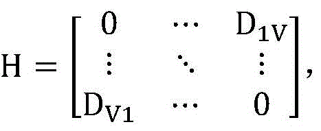
根据类间距Drg的物理意义,则有Drg=Dgr,且当r=g时,Drg=0,将上述计算得到的所有类间距用矩阵形式表示,可得到初始的N×N类间距矩阵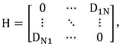
(3.2)遍历当前的类间距矩阵H,找到矩阵H中的非对角线最小元素,即当前类间距最小值,设为Dst,且s≠t,表示第s类和第t类为当前距离最近的两个类,若Dst<Dth,则将第t类中的角点归并到第s类中,进而将第s类和第t类合并为一个新类,并将合并后的角点总类数记为V,进入子步骤(3.3);否则结束聚类计算,可得到I个车牌字符预选角点集合Bi,i=1,2,3…,I,其中,i表示预选角点集合的序号;I表示车牌字符预选角点集合的总数,且I=V,该子步骤的判别条件中,Dst为当前矩阵H中的非对角线最小元素;Dth为类间距最小值阈值;(3.2) Traverse the current class spacing matrix H, find the off-diagonal minimum element in the matrix H, that is, the minimum current class spacing, set D st , and s≠t, indicating that the sth class and the tth class are the current The two closest classes, if D st < D th , merge the corners in the t-th class into the s-th class, and then merge the s-th class and the t-th class into a new class, and combine the merged The total number of corner points is denoted as V, and the sub-step (3.3) is entered; otherwise, the clustering calculation is ended, and I preselected corner point sets B i of license plate characters can be obtained, i=1, 2, 3..., I, where i represents The serial number of the pre-selected corner point set; I represents the total number of the license plate character pre-selected corner point set, and I=V, in the judgment condition of this sub-step, D st is the off-diagonal minimum element in the current matrix H; D th is the class Spacing minimum threshold;
(3.3)重新计算当前剩余的类与合并得到的新类两两之间的类间距Drg,此时类间距Drg的计算公式为:(3.3) Recalculate the class spacing D rg between the current remaining classes and the new merged class pairwise. At this time, the calculation formula of the class spacing D rg is:
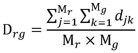
式中,Mr表示第r类中的角点个数,该类中的角点表示为pj,j=1,2,3…,Mr;Mg表示第g类中的角点个数,该类中的角点表示为qk,k=1,2,3…,Mg;djk表示角点pj和qk之间的欧式距离,即


用上述重新计算得到的类间距,根据类间距Drg及类间距矩阵H的物理意义,对类间距矩阵H进行更新,可得到新的V×V类间距矩阵
其中,在步骤(4)中,车牌定位方法如下:对于步骤(3)中聚类得到的车牌字符预选角点集合Bi,i=1,2,3…,I,从车牌字符预选角点集合Bi中筛选出车牌字符有效角点集合C,进而确定车牌位置,方法如下:Wherein, in step (4), the license plate positioning method is as follows: for the license plate character preselected corner point set B i obtained by clustering in step (3), i=1,2,3...,I, preselect the corner points from the license plate character The valid corner point set C of the license plate characters is filtered out from the set B i , and then the position of the license plate is determined. The method is as follows:
(4.1)初始化i=1;(4.1) Initialize i=1;
(4.2)若车牌字符预选角点集合Bi满足
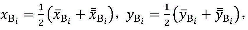
(4.3)遍历车牌字符预选角点集合Bi,确定该集合中角点的最大横坐标


(4.4)若车牌字符预选角点集合Bi满足


(4.5)若i<I,则将i的值增1,重新返回上述子步骤(4.2);否则结束车牌定位过程,返回步骤(1)图像采集及预处理。(4.5) If i<1, increase the value of i by 1, and return to the above sub-step (4.2); otherwise, end the license plate positioning process and return to step (1) image acquisition and preprocessing.
其中,在步骤(5)中,实施拖牵诱导方法如下:根据步骤(4)中车牌定位中已确定的车牌中心(x0,y0)在图像中的位置,实时给出方向提示,诱导驾驶员进行倒车作业:若图像中被拖车车牌中心在图像中心的左侧,则提示驾驶员向右倒;若图像中被拖车车牌中心在图像中心的右侧,则提示驾驶员向左倒,从而完成两侧托臂与被拖车两前轮的对准,进而对被拖车进行抱胎固定,将其牵拉拖离。Wherein, in step (5), the method of implementing the towing induction is as follows: according to the position of the license plate center (x 0 , y 0 ) in the image that has been determined in the license plate positioning in step (4), a direction prompt is given in real time, and the induction The driver is reversing: if the center of the towed license plate is on the left side of the image center in the image, the driver will be prompted to reverse to the right; if the center of the towed license plate is on the right side of the image center, the driver will be prompted to reverse to the left, In this way, the alignment of the support arms on both sides with the two front wheels of the towed vehicle is completed, and the towed vehicle is then fixed with tires and pulled away.
有益效果:与现有技术相比,本发明的技术方案具有以下有益技术效果:Beneficial effects: compared with the prior art, the technical solution of the present invention has the following beneficial technical effects:
1、针对道路救援装备的结构及正方位拖牵作业工作特点而提出,能有效加快正方位拖牵车轮对准过程,对拖牵作业形成诱导辅助,提高道路救援装备救援效率。1. According to the structure of the road rescue equipment and the working characteristics of the directional towing operation, it can effectively speed up the alignment process of the directional towing wheels, form an induction assistance for the towing operation, and improve the rescue efficiency of the road rescue equipment.
2、诱导可靠性高,抗干扰能力强,具有良好的环境适应能力。本发明所提出的诱导方法充分考虑并利用了不同车辆在车牌上共同具有的字符角点特征,能够适应各种不同的车型。2. High induction reliability, strong anti-interference ability, and good environmental adaptability. The induction method proposed by the present invention fully considers and utilizes the character corner features common to different vehicles on the license plate, and can adapt to various vehicle types.
3、处理速度快,实时性好,本发明所提出的诱导方法采用灰度图像进行角点检测,并在角点聚类前先进行角点优选,有效提高了该诱导方法的运行速度,保证了实时性。3. The processing speed is fast and the real-time performance is good. The induction method proposed by the present invention uses grayscale images to detect corner points, and performs corner point selection before corner point clustering, which effectively improves the running speed of the induction method and ensures that real-time.
附图说明Description of drawings
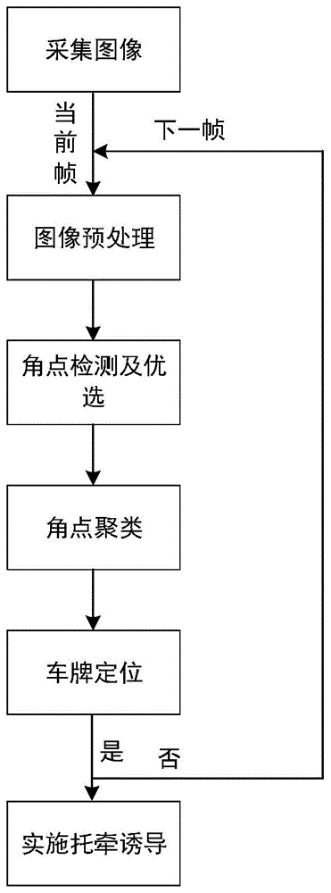
图1是本发明提出的道路救援装备正方位拖牵诱导方法的流程图;Fig. 1 is the flow chart of the road rescue equipment positive azimuth towing induction method proposed by the present invention;
图2是道路救援装备正方位拖牵作业的立体示意图;Fig. 2 is the three-dimensional schematic diagram of the towing operation of the road rescue equipment in the positive direction;
图3是道路救援装备正方位拖牵作业的俯视图;Figure 3 is a top view of the frontal towing operation of road rescue equipment;
图4是道路救援装备拖牵装置结构及摄像头安装位置示意图;Figure 4 is a schematic diagram of the structure of the road rescue equipment towing device and the installation position of the camera;
图5是采集的某帧图像;Fig. 5 is a certain frame image collected;
图6是采集图像预处理结果图;Fig. 6 is the preprocessing result diagram of the collected image;
图7是采集图像角点检测结果图;Fig. 7 is the result graph of the corner point detection of the collected image;
图8是采集图像角点优选结果图;Fig. 8 is the result diagram of the corner point optimization of the collected image;
图9是采集图像角点聚类结果图;Fig. 9 is the result graph of collecting image corner point clustering;
图10是采集图像车牌字符有效角点筛选结果图;Fig. 10 is a result of filtering the valid corner points of the license plate characters of the collected image;
图11是车牌定位结果图。Figure 11 is a result map of license plate location.
具体实施方式Detailed ways
下面结合附图和实施例对本发明的技术方案作进一步的说明。The technical solutions of the present invention will be further described below with reference to the accompanying drawings and embodiments.
随着社会经济的不断增长,我国道路交通基础设施建设及汽车工业得到飞速发展,机动车保有量在大幅增加,汽车在行驶途中由于驾驶不当或车辆自身故障等导致的车辆无法正常行驶等特殊情况与日俱增,作为汽车后市场的道路清障救援行业逐渐被社会和民众重视,道路清障救援行业对保障道路运输安全高效的重要性日益凸显。但是由于交通事故的发生具有无法彻底预防的客观必然性,在很多交通事故发生后,常有因清障救援不及时或救援效率太低而导致的城市交通拥堵或二次连锁事故,比如道路救援装备无法快速准确从正方位将事故车拖离现场而导致交通堵塞就是其中之一。究其原因,一方面正方位救援环境比较复杂,大多面对狭窄及拥堵环境,作业空间严重受限,如说明书附图2和说明书附图3所示,被拖车夹在左右两车中间,呈“三”字形排列,此时道路救援装备只能从被拖车的前方实施拖牵救援;另一方面道路救援装备智能化水平低,没有利用现有科学技术手段,对拖牵作业进行诱导辅助,也是导致救援效率低的一个重要因素,但目前对于道路救援装备正方位拖牵诱导相关技术尚未见有研究。With the continuous growth of the social economy, my country's road transportation infrastructure construction and automobile industry have developed rapidly, and the number of motor vehicles has increased significantly. The vehicles cannot be driven normally due to improper driving or the vehicle's own failure. With each passing day, the road clearance and rescue industry, as the automotive aftermarket, is gradually being valued by the society and the public. The importance of the road clearance and rescue industry to ensure the safety and efficiency of road transportation has become increasingly prominent. However, due to the objective inevitability of traffic accidents that cannot be completely prevented, after many traffic accidents, there are often urban traffic congestion or secondary chain accidents caused by untimely rescue or rescue efficiency, such as road rescue equipment. One of them is the inability to quickly and accurately tow the accident vehicle away from the scene and cause traffic jams. The reason is that, on the one hand, the frontal rescue environment is relatively complex, most of them face a narrow and congested environment, and the working space is severely limited. The "three" shape is arranged. At this time, the road rescue equipment can only carry out towing rescue from the front of the towed vehicle; on the other hand, the intelligent level of the road rescue equipment is low, and the existing scientific and technological means are not used to induce and assist the towing operation. It is also an important factor that leads to low rescue efficiency, but there is no research on the related technology of road rescue equipment directional drag induction.
以皮卡救援车为例的道路救援装备的拖牵装置主要由折臂、伸缩臂、摆臂及两侧托臂组成,具体形式如附图4所示。在正方位拖牵作业实施的过程中,道路救援装备位于被拖车车头的前方,首先道路救援装备通过倒车作业,将其两侧托臂分别与被拖车两前轮进行对准,然后对被拖车两前轮进行抱胎固定,最后通过折臂牵拉起吊,将被拖车拖离。在传统的正方位拖牵作业过程中,将被拖车前轮与道路救援装备托臂进行对准这一操作,其效率主要依赖于驾驶员技术经验等人为因素,通常需要多次反复倒车进行位置修正,作业耗时过长,救援效率低下。Taking the pickup truck rescue vehicle as an example, the towing device of the road rescue equipment is mainly composed of a folding arm, a telescopic arm, a swing arm and two supporting arms, and the specific form is shown in Figure 4. During the implementation of the towing operation in the positive direction, the road rescue equipment is located in front of the head of the towed vehicle. First, the road rescue equipment through the reversing operation, aligns its two side arms with the two front wheels of the towed vehicle, and then aligns the two front wheels of the towed vehicle. The two front wheels are fixed by holding the tires, and finally pulled and lifted by the folding arm, which will be towed away by the trailer. In the traditional directional towing operation, the operation of aligning the front wheel of the towed vehicle with the support arm of the road rescue equipment mainly depends on the driver's technical experience and other human factors, and usually requires repeated reversing to position the vehicle Correction, the operation takes too long and the rescue efficiency is low.
针对道路救援装备正方位拖牵作业的特点,本发明提出一种既具有良好实时性,又具有较强环境自适应能力和抗干扰能力的道路救援装备正方位拖牵诱导方法,总流程参见说明书附图1,该方法主要包括下面几个步骤:Aiming at the characteristics of road rescue equipment directional towing operation, the present invention proposes a forward azimuth towing induction method for road rescue equipment, which not only has good real-time performance, but also has strong environmental adaptability and anti-interference ability. Accompanying drawing 1, this method mainly comprises the following steps:
(1)图像采集及预处理(1) Image acquisition and preprocessing
在道路救援装备尾部折臂上离地面40~60厘米处的中间位置上安装车载摄像头,摄像头水平朝向救援装备的后方,其采集范围为包含救援装备摆臂、托臂及被拖车车头等关键部位的后方作业区域,具体形式如说明书附图4所示。对采集的后方作业区域图像,参见说明书附图5,进行预处理,参见说明书附图6:先将彩色采集图像转成灰度图像,减小图像处理数据量,提高该方法的实时性,然后对灰度图像进行3×3邻域高斯平滑滤波,消除一些不必要的孤立点和凸起。Install a vehicle-mounted camera at the middle position of the rear folded arm of the road rescue equipment at a distance of 40-60 cm from the ground. The camera is horizontally facing the rear of the rescue equipment. The specific form of the rear working area is shown in Figure 4 of the manual. For the collected image of the rear working area, see Figure 5 in the description, and preprocess it, see Figure 6 in the description: first convert the color captured image into a grayscale image, reduce the amount of image processing data, and improve the real-time performance of the method, and then A 3×3 neighborhood Gaussian smoothing filter is performed on the grayscale image to remove some unnecessary outliers and bulges.
(2)角点检测及优选(2) Corner detection and optimization
应当指出,目前国内大部分社会车辆为蓝牌小型汽车,本发明所提出的诱导方法主要面向蓝牌小型汽车的拖牵救援,而车辆牌照是大部分社会车辆的共同特征,具有普遍性,且车牌字符属于印刷字符,字符笔画中蕴含比较丰富的角点信息,因此可通过角点检测提取车牌区域角点特征。It should be pointed out that at present, most of the social vehicles in China are blue-brand small cars, and the induction method proposed by the present invention is mainly oriented to the towing and rescue of blue-brand small cars, and the vehicle license plate is a common feature of most social vehicles, which is universal, and License plate characters belong to printed characters, and the character strokes contain relatively rich corner information, so corner features of the license plate area can be extracted through corner detection.
典型的角点检测方法包括Moravec角点检测、Susan角点检测、Fast角点检测、Harris角点检测等算法,其中Moravec角点检测算法简单,但计算量大,误检率很高,Susan角点检测算法对噪声不敏感,但定位精度较差,Harris角点检测算法简单,计算量不大,角点提取较为均匀,适应性强,具有较好的稳定性。本发明采用哈里斯(Harris)角点检测算法对平滑后的灰度图像进行检测,获得图像中的角点,参见说明书附图7,并将得到的所有角点存储到角点集合O中。Typical corner detection methods include Moravec corner detection, Susan corner detection, Fast corner detection, Harris corner detection and other algorithms. Among them, the Moravec corner detection algorithm is simple, but it requires a large amount of calculation and has a high false detection rate. The point detection algorithm is not sensitive to noise, but the positioning accuracy is poor. The Harris corner detection algorithm is simple, the calculation amount is not large, the corner extraction is relatively uniform, the adaptability is strong, and it has good stability. The present invention uses the Harris corner detection algorithm to detect the smoothed grayscale image, obtains the corners in the image, see FIG.
Harris角点检测的位置相对准确,角点提取也相对较为均匀,但所得到的角点位置大多还是以邻域的形式成批出现的,参见说明附图7,为了进一步减小后续角点聚类过程中的计算量,提高该诱导方法的实时性,可根据角点强度对上述Harris角点检测获得的角点进行优选,获得更具代表性的角点位置。正方位拖牵作业的有效作业距离一般为1~5米,摄像头的焦距选择为4~8毫米,本发明中摄像头采集的图像尺寸为960×540,可设置角点间最小允许距离为5像素,对Harris角点检测获得的角点进行优选,得到优质角点集合A,参见说明书附图8,具体子步骤为:The position of Harris corner point detection is relatively accurate, and the corner point extraction is relatively uniform, but most of the obtained corner point positions appear in batches in the form of neighborhoods. The calculation amount in the class process is improved, the real-time performance of the induction method is improved, and the corner points obtained by the above Harris corner point detection can be optimized according to the corner point strength to obtain a more representative corner point position. The effective working distance of the towing operation in the positive direction is generally 1 to 5 meters, the focal length of the camera is selected to be 4 to 8 mm, the size of the image collected by the camera in the present invention is 960 × 540, and the minimum allowable distance between the corner points can be set to 5 pixels. , optimize the corner points obtained by Harris corner point detection to obtain a high-quality corner point set A, see Figure 8 in the description, and the specific sub-steps are:
(2.1)按照角点横、纵坐标依次递增的顺序,遍历角点集合O中的所有角点,并在以每个角点为中心,半径为5像素的圆形区域内,将该区域角点强度最大的角点保存到优质角点集合A中;(2.1) Traverse all the corner points in the corner point set O in the order of increasing horizontal and vertical coordinates of the corner points, and in a circular area with each corner point as the center and a radius of 5 pixels, the corner of the area is The corner point with the highest point intensity is saved to the high-quality corner point set A;
(2.2)上述遍历结束后,对优质角点集合A中重复保存的具有相同坐标及角点强度的角点,只保留其中一个,并将多余的相同角点从优质角点集合A中删除,最后可得到N个不同的优质角点。(2.2) After the above traversal is completed, only one of the corner points with the same coordinates and corner strengths that are repeatedly saved in the high-quality corner point set A is retained, and the redundant identical corner points are deleted from the high-quality corner point set A. Finally, N different high-quality corner points can be obtained.
(3)角点聚类(3) Corner clustering
车牌区域字符角点分布密集且有规则,可根据角点之间的距离对优选得到的优质角点集合A进行凝聚层次聚类,参见说明书附图9,得到I个车牌字符预选角点集合Bi,i=1,2,3…,I,其中,i表示预选角点集合的序号,具体子步骤为:The distribution of character corner points in the license plate area is dense and regular, and agglomerative hierarchical clustering can be carried out to the high-quality corner point set A that is preferably obtained according to the distance between the corner points, referring to the accompanying drawing 9 of the description, obtain 1 license plate character pre-selected corner point set B i , i=1,2,3...,I, where i represents the sequence number of the pre-selected corner point set, and the specific sub-steps are:
(3.1)把优质角点集合A中的每个角点an,n=1,2,3…,N,各视为一个类,每个类中有且只有一个角点,计算当前所有类两两之间的类间距Drg,Drg表示第r类和第g类之间的类间距,本发明中定义类间距Drg为第r类中的每个角点与第g类中的每个角点之间欧式距离的平均值,由于当前每个类中有且只有一个角点,即第r类中只有角点ar,第g类中只有角点ag,故此时类间距Drg计算公式为:(3.1) Treat each corner point an , n =1, 2, 3..., N in the high-quality corner point set A as a class, each class has one and only one corner point, calculate all current classes The class distance D rg between pairs, D rg represents the class distance between the rth class and the gth class. In the present invention, the class distance D rg is defined as the difference between each corner point in the rth class and the distance between the gth class. The average value of the Euclidean distance between each corner point. Since there is only one corner point in each class, that is, only the corner point a r in the rth class, and only the corner point a g in the gth class, so at this time the class distance The formula for calculating D rg is:
Drg=drg D rg =d rg
式中,drg表示角点ar和ag之间的欧式距离,即


根据类间距Drg的物理意义,则有Drg=Dgr,且当r=g时,Drg=0,将上述计算得到的所有类间距用矩阵形式表示,可得到初始的N×N类间距矩阵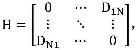
(3.2)遍历当前的类间距矩阵H,找到矩阵H中的非对角线最小元素,即当前类间距最小值,设为Dst,且s≠t,表示第s类和第t类为当前距离最近的两个类。若Dst<Dth,则将第t类中的角点归并到第s类中,进而将第s类和第t类合并为一个新类,并将合并后的角点总类数记为V,进入子步骤(3.3);否则结束聚类计算,可得到I个车牌字符预选角点集合Bi,i=1,2,3…,I,其中,i表示预选角点集合的序号;I表示车牌字符预选角点集合的总数,且I=V。该子步骤的判别条件中,Dst为当前矩阵H中的非对角线最小元素;Dth为类间距最小值阈值,该阈值在10~15内取值;(3.2) Traverse the current class spacing matrix H, find the off-diagonal minimum element in the matrix H, that is, the minimum current class spacing, set D st , and s≠t, indicating that the sth class and the tth class are the current The two closest classes. If D st < D th , merge the corners in the t-th class into the s-th class, and then merge the s-th class and the t-th class into a new class, and record the total number of corners after the merge as V, enter sub-step (3.3); otherwise, end the clustering calculation, and obtain I license plate character pre-selected corner point sets B i , i=1,2,3...,I, wherein, i represents the sequence number of the pre-selected corner point set; I represents the total number of preselected corner point sets of license plate characters, and I=V. In the discrimination conditions of this sub-step, D st is the off-diagonal minimum element in the current matrix H; D th is the minimum threshold of the class spacing, and the threshold is within 10 to 15;
(3.3)重新计算当前剩余的类与合并得到的新类两两之间的类间距Drg,此时类间距Drg的计算公式为:(3.3) Recalculate the class spacing D rg between the current remaining classes and the new merged class pairwise. At this time, the calculation formula of the class spacing D rg is:

式中,Mr表示第r类中的角点个数,该类中的角点表示为pj,j=1,2,3…,Mr;Mg表示第g类中的角点个数,该类中的角点表示为qk,k=1,2,3…,Mg;djk表示角点pj和qk之间的欧式距离,即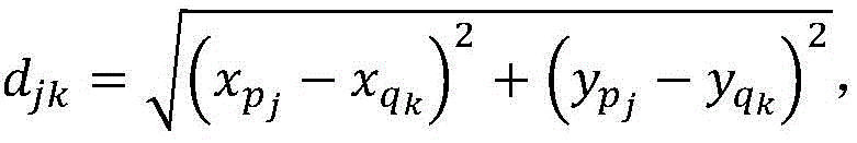


用上述重新计算得到的类间距,根据类间距Drg及类间距矩阵H的物理意义,对类间距矩阵H进行更新,可得到新的V×V类间距矩阵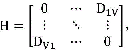
(4)车牌定位(4) License plate positioning
对于步骤(3)中聚类得到的车牌字符预选角点集合Bi,i=1,2,3…,I,根据车牌尺寸的先验性知识,从车牌字符预选角点集合Bi中筛选出车牌字符有效角点集合C,参见说明书附图10,进而确定车牌位置,参见说明书附图11,具体子步骤为:For the license plate character pre-selected corner point set B i obtained by clustering in step (3), i=1,2,3...,I, according to the prior knowledge of the license plate size, filter from the license plate character pre-selected corner point set B i For the set C of valid corner points of the characters of the license plate, see Figure 10 in the description, and then determine the position of the license plate, see Figure 11 in the description, and the specific sub-steps are:
(4.1)初始化i=1;(4.1) Initialize i=1;
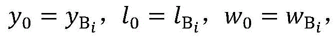
(4.2)若车牌字符预选角点集合Bi满足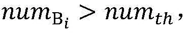

(4.3)遍历车牌字符预选角点集合Bi,确定该集合中角点的最大横坐标


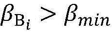


(4.4)若车牌字符预选角点集合Bi满足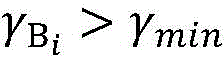


(4.5)若i<I,则将i的值增1,重新返回上述子步骤(4.2);否则结束车牌定位过程,返回步骤(1)图像采集及预处理。(4.5) If i<1, increase the value of i by 1, and return to the above sub-step (4.2); otherwise, end the license plate positioning process and return to step (1) image acquisition and preprocessing.
上述车牌字符有效角点集合筛选算法的两点补充说明:①国内的蓝色牌照具有国家标准,其印刷字符均为七位,其中每个字符至少含有一个角点,七位印刷字符的长宽比约为4;②摄像头安装在道路救援装备折臂的中间固定位置处,且水平朝向道路救援装备后方,在进行正方位拖牵作业的过程中,被拖车位于道路救援装备的后方区域,作业距离一般为1~5米,摄像头的焦距可选择为4~8毫米,本发明中摄像头采集的图像尺寸为960×640,在有效作业距离1~5米范围内,采集图像中车牌字符区域的像素大小在300~5000范围内变化。Two supplementary explanations for the above-mentioned effective corner point set screening algorithm for license plate characters: ① The domestic blue license plate has a national standard, and its printed characters are all seven digits, of which each character contains at least one corner point, and the length and width of the seven printed characters are The ratio is about 4; ② The camera is installed at the middle fixed position of the road rescue equipment folding arm, and faces the rear of the road rescue equipment horizontally. During the forward towing operation, the towed vehicle is located in the rear area of the road rescue equipment. The distance is generally 1 to 5 meters, and the focal length of the camera can be selected to be 4 to 8 mm. The pixel size varies from 300 to 5000.
(5)实施拖牵诱导(5) Implement drag induction
如说明书附图4所示,在正方位拖牵作业的实施过程中,道路救援装备一般位于被拖车车头的前方,二者近似呈“一”字形排列,车载摄像头安装于道路救援装备折臂上中间固定位置处,且水平朝向道路救援装备后方,摄像头采集区域的中轴线与道路救援装备及其拖牵装置的中轴线相一致,而被拖车前车牌一般位于其车头中间位置,因而可根据摄像头输出画面的中心与画面中被拖车车牌中心的左右位置关系判断道路救援装备与被拖车的相对位置关系。As shown in Figure 4 of the description, during the implementation of the towing operation in the positive direction, the road rescue equipment is generally located in front of the head of the towed vehicle, and the two are approximately arranged in a "one" shape, and the on-board camera is installed on the folding arm of the road rescue equipment. At the fixed position in the middle, and horizontally facing the rear of the road rescue equipment, the central axis of the camera capture area is consistent with the central axis of the road rescue equipment and its towing device, and the license plate in front of the towed vehicle is generally located in the middle of the front of the vehicle. The left and right positional relationship between the center of the output screen and the center of the license plate of the towed vehicle in the screen determines the relative positional relationship between the road rescue equipment and the towed vehicle.
在实施正方位拖牵作业的过程中,驾驶员面向道路救援装备前方,故可根据步骤(4)中车牌定位中已确定的车牌中心(x0,y0)在图像中的位置,参见说明书附图11,实时给出方向提示,诱导驾驶员进行倒车作业:若图像中被拖车车牌中心在图像中心的左侧,则提示驾驶员向右倒;若图像中被拖车车牌中心在图像中心的右侧,则提示驾驶员向左倒,从而完成两侧托臂与被拖车两前轮的对准,进而对被拖车进行抱胎固定,将其牵拉拖离。In the process of carrying out the azimuth towing operation, the driver faces the front of the road rescue equipment, so the position of the license plate center (x 0 , y 0 ) in the image that has been determined in the license plate positioning in step (4) can be referred to the manual. Figure 11, the direction prompt is given in real time to induce the driver to reverse the vehicle: if the center of the license plate of the towed vehicle is on the left side of the center of the image, the driver is prompted to reverse to the right; On the right side, the driver is prompted to fall to the left, so as to complete the alignment of the support arms on both sides with the two front wheels of the towed vehicle, and then fix the towed vehicle with tires and pull it away.
经过上述步骤,本发明提出的方法能够实现救援装备正方位拖牵作业过程中的实时诱导,有效提高了道路救援装备的救援效率。After the above steps, the method proposed by the present invention can realize the real-time induction during the positive azimuth towing operation of the rescue equipment, and effectively improve the rescue efficiency of the road rescue equipment.
Claims (4)


Priority Applications (3)
| Application Number | Priority Date | Filing Date | Title |
|---|---|---|---|
| CN201810920734.XA CN109376734B (en) | 2018-08-13 | 2018-08-13 | A positive azimuth towing induction method for road rescue equipment based on license plate corner features |
| US17/057,915 US11367215B2 (en) | 2018-08-13 | 2019-05-29 | Positive azimuth towing guidance method for road rescue equipment based on license plate corner features |
| PCT/CN2019/089077 WO2020034722A1 (en) | 2018-08-13 | 2019-05-29 | License-plate corner point feature-based method for roadside assistance equipment to perform towing and guiding from the front |
Applications Claiming Priority (1)
| Application Number | Priority Date | Filing Date | Title |
|---|---|---|---|
| CN201810920734.XA CN109376734B (en) | 2018-08-13 | 2018-08-13 | A positive azimuth towing induction method for road rescue equipment based on license plate corner features |
Publications (2)
| Publication Number | Publication Date |
|---|---|
| CN109376734A CN109376734A (en) | 2019-02-22 |
| CN109376734B true CN109376734B (en) | 2020-07-31 |
Family
ID=65404377
Family Applications (1)
| Application Number | Title | Priority Date | Filing Date |
|---|---|---|---|
| CN201810920734.XA Expired - Fee Related CN109376734B (en) | 2018-08-13 | 2018-08-13 | A positive azimuth towing induction method for road rescue equipment based on license plate corner features |
Country Status (3)
| Country | Link |
|---|---|
| US (1) | US11367215B2 (en) |
| CN (1) | CN109376734B (en) |
| WO (1) | WO2020034722A1 (en) |
Families Citing this family (5)
| Publication number | Priority date | Publication date | Assignee | Title |
|---|---|---|---|---|
| CN109376734B (en) | 2018-08-13 | 2020-07-31 | 东南大学 | A positive azimuth towing induction method for road rescue equipment based on license plate corner features |
| US12183028B2 (en) * | 2019-12-04 | 2024-12-31 | Beijing Smarter Eye Technology Co. Ltd. | Object-based short range measurement method, device and system, and storage medium |
| CN113077513B (en) | 2021-06-03 | 2021-10-29 | 深圳市优必选科技股份有限公司 | Visual positioning method and device and computer equipment |
| CN119942520A (en) * | 2024-12-15 | 2025-05-06 | 北京工业大学 | A 3D target detection method for vehicle formation based on license plate information |
| CN120235860B (en) * | 2025-05-29 | 2025-07-25 | 西安嘉和华亨热系统有限公司 | Intelligent recognition method for surface cracks in radiator vibration test |
Citations (2)
| Publication number | Priority date | Publication date | Assignee | Title |
|---|---|---|---|---|
| CN103632550A (en) * | 2013-11-05 | 2014-03-12 | 广东工业大学 | Method and system for identifying vehicles on road on basis of fixed cameras |
| CN106027997A (en) * | 2016-07-13 | 2016-10-12 | 孙福盛 | Device and method for positioning container truck under assistance of wireless video |
Family Cites Families (10)
| Publication number | Priority date | Publication date | Assignee | Title |
|---|---|---|---|---|
| US9238483B2 (en) * | 2011-04-19 | 2016-01-19 | Ford Global Technologies, Llc | Trailer backup assist system with trajectory planner for multiple waypoints |
| WO2014152470A2 (en) * | 2013-03-15 | 2014-09-25 | Tk Holdings, Inc. | Path sensing using structured lighting |
| AT514588B1 (en) * | 2013-08-29 | 2015-02-15 | Univ Wien Tech | Method for controlling a vehicle |
| US9464886B2 (en) * | 2013-11-21 | 2016-10-11 | Ford Global Technologies, Llc | Luminescent hitch angle detection component |
| US20160375831A1 (en) * | 2015-06-23 | 2016-12-29 | GM Global Technology Operations LLC | Hitching assist with pan/zoom and virtual top-view |
| US9696723B2 (en) * | 2015-06-23 | 2017-07-04 | GM Global Technology Operations LLC | Smart trailer hitch control using HMI assisted visual servoing |
| CN107861510A (en) | 2017-11-01 | 2018-03-30 | 龚土婷 | A kind of intelligent vehicle control loop |
| US11669104B2 (en) * | 2018-05-08 | 2023-06-06 | Continental Automotive Systems, Inc. | User-adjustable trajectories for automated vehicle reversing |
| US11603100B2 (en) * | 2018-08-03 | 2023-03-14 | Continental Autonomous Mobility US, LLC | Automated reversing by following user-selected trajectories and estimating vehicle motion |
| CN109376734B (en) | 2018-08-13 | 2020-07-31 | 东南大学 | A positive azimuth towing induction method for road rescue equipment based on license plate corner features |
-
2018
- 2018-08-13 CN CN201810920734.XA patent/CN109376734B/en not_active Expired - Fee Related
-
2019
- 2019-05-29 US US17/057,915 patent/US11367215B2/en active Active
- 2019-05-29 WO PCT/CN2019/089077 patent/WO2020034722A1/en not_active Ceased
Patent Citations (2)
| Publication number | Priority date | Publication date | Assignee | Title |
|---|---|---|---|---|
| CN103632550A (en) * | 2013-11-05 | 2014-03-12 | 广东工业大学 | Method and system for identifying vehicles on road on basis of fixed cameras |
| CN106027997A (en) * | 2016-07-13 | 2016-10-12 | 孙福盛 | Device and method for positioning container truck under assistance of wireless video |
Also Published As
| Publication number | Publication date |
|---|---|
| CN109376734A (en) | 2019-02-22 |
| WO2020034722A1 (en) | 2020-02-20 |
| US11367215B2 (en) | 2022-06-21 |
| US20210312653A1 (en) | 2021-10-07 |
Similar Documents
| Publication | Publication Date | Title |
|---|---|---|
| CN109376734B (en) | A positive azimuth towing induction method for road rescue equipment based on license plate corner features | |
| CN110232835B (en) | Underground garage parking space detection method based on image processing | |
| CN106064587B (en) | A multi-lane inter-vehicle distance recognition method and device based on license plate recognition | |
| CN110443225A (en) | A virtual and real lane line recognition method and device based on feature pixel statistics | |
| CN110733416B (en) | A Lane Departure Warning Method Based on Inverse Perspective Transformation | |
| CN109299674B (en) | Tunnel illegal lane change detection method based on car lamp | |
| WO2019200938A1 (en) | Early warning system for vehicles rolling on line | |
| CN101750049A (en) | Monocular vision vehicle distance measuring method based on road and vehicle information | |
| CN201825037U (en) | Lane departure alarm device for vehicles on highway | |
| CN101608924A (en) | A Lane Line Detection Method Based on Gray Level Estimation and Cascaded Hough Transform | |
| CN107284455B (en) | An ADAS system based on image processing | |
| CN106156723A (en) | A kind of crossing fine positioning method of view-based access control model | |
| CN103150556A (en) | Safety belt automatic detection method for monitoring road traffic | |
| CN111539303A (en) | Monocular vision-based vehicle driving deviation early warning method | |
| CN106887004A (en) | A kind of method for detecting lane lines based on Block- matching | |
| CN104966049A (en) | Lorry detection method based on images | |
| CN111783666A (en) | A Fast Lane Line Detection Method Based on Corner Feature Matching of Continuous Video Frames | |
| CN103699899B (en) | Method for detecting lane lines based on equidistant curve model | |
| CN105654073A (en) | Automatic speed control method based on visual detection | |
| CN105966314B (en) | Lane departure warning method based on double inexpensive cameras | |
| CN110335467A (en) | A Method of Using Computer Vision to Realize Vehicle Behavior Detection on Expressway | |
| CN103481842B (en) | A kind of changing method of moving vehicles detection and tracking pattern | |
| CN105059184A (en) | Device for early warning, active prevention, and active control of side tumbling of passenger vehicle at bend, and judgment method thereof | |
| CN107220632B (en) | A road image segmentation method based on normal feature | |
| CN109285169B (en) | Road rescue equipment side direction towing induction method based on wheel identification |
Legal Events
| Date | Code | Title | Description |
|---|---|---|---|
| PB01 | Publication | ||
| PB01 | Publication | ||
| SE01 | Entry into force of request for substantive examination | ||
| SE01 | Entry into force of request for substantive examination | ||
| GR01 | Patent grant | ||
| GR01 | Patent grant | ||
| CF01 | Termination of patent right due to non-payment of annual fee | ||
| CF01 | Termination of patent right due to non-payment of annual fee |
Granted publication date: 20200731 |