Detailed Description
Embodiments of the present invention are described below with reference to the drawings so as to be easily implemented by those skilled in the art. It will be appreciated by those skilled in the art that the embodiments described below can be modified in various ways without departing from the spirit and scope of the invention and are not limited to the embodiments described herein. In order to clearly explain the present invention, portions that are not related to the description are omitted in the drawings, and the same reference numerals are given to the same or similar components throughout the specification.
As shown in fig. 1, an iontophoresis device 100 according to an embodiment of the present invention includes a power supply unit 110, two contact electrodes 121 and 122, and a control unit 130.
When power is applied, the two contact electrodes 121, 122 generate a potential difference in the skin of the user to change the electrical environment of the skin, thereby increasing skin penetration of the ionic drug or the active ingredient.
That is, the two contact electrodes 121 and 122 are used to realize an iontophoresis function, and when a current is applied to the skin of the user by the power supplied from the power supply unit 110, the skin of the user and the two contact electrodes 121 and 122 constitute a closed circuit, so that the movement of ions can occur. Wherein the power supply unit 110 may be a known battery, and when the iontophoresis device 100 according to the present invention is applied to the beauty treatment apparatus 1000, the power supply unit 110 may be a battery (see reference numeral 110 of fig. 5) for driving the beauty treatment apparatus 1000.
For example, when the ionic drug or the active ingredient is applied to the skin of the user, the two contact electrodes 121 and 122 are brought into contact with the skin of the user, and then a current is applied to the two contact electrodes 121 and 122, an iontophoresis effect is produced in which the ionic drug or the active ingredient applied to the skin of the user is ionized, and the ionic drug or the active ingredient easily penetrates through the skin mucosa and into the skin tissue.
At this time, when a current is caused to flow through the skin of the user through the two contact electrodes 121 and 122 by the power supplied from the power supply unit 110, the amount of the current flowing through the skin of the user may vary according to the skin state of the user. Thus, even if voltages of the same magnitude are applied to the two contact electrodes 121, 122, the intensity of the electrical stimulation felt by the user may vary according to the skin state of the user.
This is because the magnitude of the skin resistance may be different according to the moisture content contained in the skin of the user or the thickness of the skin of the user, and may also be different according to the coating thickness of the ionic drug or the active ingredient coated on the skin surface of the user for the iontophoresis function.
For example, even if the same magnitude of voltage is applied to the contact electrodes 121 and 122, in the case where the user's skin is in a dry state with a low moisture content or the user's skin is thick, the skin resistance may be relatively increased as compared to the case where the user's skin is in a wet state with a high moisture content or the user's skin is thin. Thus, when the user's skin is in a dry state with a low moisture content or the user's skin is thick, the intensity of the electrical stimulation felt by the user may be low because the amount of current flowing through the user's skin is small. In contrast, in the case where the user's skin is in a wet state with a high moisture content or the user's skin is thin, the amount of current flowing through the user's skin increases because the skin resistance is relatively small compared to the above case, and thus the intensity of the electrical stimulation felt by the user is relatively high.
Even if the same voltage is applied to the contact electrodes 121 and 122, if the coating thickness of the ionic drug or the active ingredient applied to the skin of the user is small, the amount of current flowing through the ionic drug or the active ingredient is relatively reduced as compared to the case where the coating thickness of the ionic drug or the active ingredient is large. Thus, the intensity of the electrical stimulation felt by the user may be relatively low as compared to the case where the coating thickness of the ionic drug or the active ingredient is thick. In contrast, when the ionic drug or the active ingredient applied to the skin of the user is applied in a thick thickness, the amount of current flowing through the ionic drug or the active ingredient is relatively increased as compared with the above case, and thus the intensity of the electrical stimulation felt by the user is relatively high.
In the present invention, the output value of any one of the voltage and current applied to the above-described contact electrodes 121, 122 may be adjusted according to the skin state of the user, so that the user can always feel the constant-intensity electrical stimulation regardless of the skin state.
The factors for determining the skin condition of the user include at least one of the moisture content of the skin surface of the user, the thickness of the skin of the user in contact with the contact electrodes 121 and 122, the presence or absence of the ionic drug or the active ingredient, and the coating thickness of the ionic drug or the active ingredient to be coated.
For example, the output value may be adjusted by changing any one of the magnitude of the voltage applied to the contact electrodes 121 and 122, the magnitude of the current, and the duty ratio (b/a) of the pulse current, that is, by changing any one of the magnitude of the voltage applied to the contact electrodes 121 and 122, the magnitude of the current, and the duty ratio of the pulse current based on the amount of change in the voltage value or the amount of change in the current value that changes according to the state of the skin of the user in contact with the two contact electrodes 121 and 122 when power is applied.
For this, the control unit 130 may include: a sensing unit 131 that determines a skin state of the user; an integrated control unit 133 for determining the skin state of the user measured by the sensing unit 131 and controlling the overall operation; and an output generating unit 132 for changing the output value according to the signal outputted from the integrated control unit 133.
The control unit 130 may be implemented in the form of a chip set mounted on one surface of the circuit board 244, and when the iontophoresis device 100 according to the present invention is applied to the skin beauty apparatus 1000, the control unit 130 may also function to control the entire driving of the skin beauty apparatus 1000. The integrated control unit 133 may calculate the output value output from the output generation unit 132 based on a variation amount of the voltage value or a variation amount of the current value according to the skin state change of the user.
At this time, the sensing unit 131 may confirm whether the two contact electrodes 121 and 122 are in contact with the skin of the user based on the magnitude of the voltage value or the current value measured between the two contact electrodes 121 and 122.
For example, in a state where the two contact electrodes 121 and 122 are not in contact with the skin, when power is applied, current does not flow due to infinite resistance, and a voltage applied between the two contact electrodes 121 and 122 may have the same magnitude as the applied voltage.
However, in a state where the two contact electrodes 121 and 122 are in contact with the skin, when power is applied, a current flows according to the skin of the user, so that a current of a predetermined magnitude or a voltage drop due to skin resistance may be measured.
Based on the above principle, when the variation amount of the voltage value or the current value measured by the sensing unit 131 is equal to or larger than a predetermined magnitude when power is applied, the control unit 130 determines that the skin is in contact with the two contact electrodes 121 and 122, and applies an output value of a predetermined magnitude to the two contact electrodes 121 and 122 by the output generation unit 132.
The integrated control unit 133 may store a voltage value or a change amount of a current value according to a change in a skin state of a user through a lookup table, thereby changing any one of a magnitude of a voltage, a magnitude of a current, and a duty ratio of a pulse current output through the output generating unit 132. The voltage value or the current value stored in the lookup table may be information that matches the voltage value or the current value measured by the sensing unit 131 in a one-to-one manner.
As an example, when the voltage applied between the two contact electrodes 121 and 122 becomes 1V or more, the control unit 130 determines that the contact electrodes 121 and 122 are in a state of being in contact with the skin of the user, and thus may apply a voltage of a predetermined magnitude (e.g., 25V) to the contact electrodes 121 and 122.
In this state, when the variation of the voltage applied to the two contact electrodes 121 and 122, which is generated according to the skin condition of the user, is 1V or more, the integrated control unit 133 determines the skin condition of the user based on the variation amount of the voltage value measured by the sensing unit 131 in the control unit 130, and the output generation unit 132 outputs a voltage of 20 to 25V or adjusts the magnitude of the current applied to the skin side through a variable resistance according to the determined skin condition of the user. Thus, the user can always feel the electrical stimulation of constant intensity regardless of the skin state.
That is, if the current can smoothly flow along the skin of the user due to the skin of the user being wet, the integrated control unit 133 may decrease the magnitude of the output voltage output from the output generation unit 132 to 20V so that the intensity of the stimulation is weak, and if the amount of current flowing along the skin of the user is relatively small due to the skin of the user being dry, the integrated control unit 133 may increase the magnitude of the output voltage output from the output generation unit 132 to 25V so that the intensity of the stimulation is increased, so that the user can always feel the electrical stimulation of a constant intensity regardless of the skin state.
As another mode, when the voltage applied between the two contact electrodes 121 and 122 becomes 1V or more, the control unit 130 determines that the contact electrodes 121 and 122 are in a state of being in contact with the skin of the user, so that a pulse current having a duty ratio of 30% may be applied to the contact electrodes 121 and 122.
In this state, when the voltage applied to the two contact electrodes 121 and 122 is changed according to the skin state of the user, the integrated control unit 133 in the control unit 130 determines the skin state of the user based on the change amount of the voltage value measured by the sensing unit 131, and controls the output generation unit 132 to output the pulse current such that the duty ratio of the pulse current is in the range of 25 to 35% according to the determined skin state of the user, so that the user can feel the same magnitude of electrical stimulation.
That is, if the current can smoothly flow along the skin of the user due to the skin of the user being wet, the integrated control unit 133 may decrease the duty ratio of the pulse current output from the output generation unit 132 to 25% so that the intensity of the stimulus is weak, and if the amount of current flowing along the skin of the user is relatively small due to the skin of the user being dry, the integrated control unit 133 may increase the duty ratio of the pulse current output from the output generation unit 132 to 35% so that the intensity of the stimulus is increased. Thus, the user can always feel the electrical stimulation of constant intensity regardless of the skin state, as in the above-described method.
In addition, in the iontophoresis device 100 according to the present invention, even if the skin state of the user is changed due to the penetration of the ionic drug or the active ingredient applied to the skin of the user into the skin, the amount of change in the voltage value is measured in real time by the sensing unit 131, so that the integrated control unit 133 can control the output generation unit 132 to output an output value suitable for the current skin state of the user. Thus, the user always feels an electrical stimulus of uniform intensity during the operation time of the iontophoresis device 100.
It should be understood that, in the present invention, although it is exemplified that the voltage applied to adjust the intensity of the electrical stimulation felt by the user is varied within a range of 23 to 25V or the duty ratio of the pulse current is varied within a range of 25 to 35%, the present invention is not limited thereto and may be modified within a different range according to the design conditions.
On the other hand, when the iontophoresis device 100 is driven by operating the switch unit (see reference numeral 140 in fig. 5), the voltages applied to the contact electrodes 121 and 122 may be always applied at the same magnitude, but the magnitude of the voltage applied to the two contact electrodes 121 and 122 to confirm whether the contact electrodes 121 and 122 are in contact with the skin may be relatively smaller than the magnitude of the voltage applied to the two contact electrodes 121 and 122 to permeate the ionic drug or the active ingredient applied to the skin of the user into the skin.
That is, in an initial state in which the iontophoresis device 100 is driven by operating the switch unit 140, a small voltage of about 10V may be applied to confirm whether the contact electrodes 121 and 122 are in contact with the skin, and in a state in which whether the contact electrodes 121 and 122 are in contact with the skin, a voltage of 25V, which is relatively greater than the voltage in the initial state, may be applied to the two contact electrodes 121 and 122 to smoothly permeate the ionic drug or the active ingredient applied to the skin of the user into the skin. This is to prevent power from being unnecessarily consumed in the standby state to increase the use time of the power supply unit 110.
Also, the iontophoresis device 100 according to the present invention can be changed to a plurality of output modes having different ranges of output values by controlling the above-described control unit 130 when the switch unit 140 is operated by the user. As an example, the switch unit 140 may be implemented as at least one button 142 that can be pressed by a user, and a strong mode, a general mode, and a weak mode, which are different in intensity of electrical stimulation, may be switched by a control signal of the control unit 130 based on the number of times the button 142 is pressed.
Specifically, when the user operates the button 142 to drive the control unit 130 in the strong mode, the magnitude of the voltage applied to the two contact electrodes 121 and 122 may be varied within a range of 35 to 45V according to the skin condition of the user, when the control unit 130 is driven in the normal mode, the magnitude of the voltage applied to the two contact electrodes 121 and 122 may be varied within a range of 25 to 35V according to the skin condition of the user, and when the control unit 130 is driven in the weak mode, the magnitude of the voltage applied to the two contact electrodes 121 and 122 may be varied within a range of 15 to 25V according to the skin condition of the user.
As another example, when the user drives the control unit 130 in the strong mode by operating the button 142, the duty ratio of the pulse current applied to the two contact electrodes 121 and 122 may be varied within a range of 60 to 80% according to the skin condition of the user, when the control unit 130 is driven in the normal mode, the duty ratio of the pulse current applied to the two contact electrodes 121 and 122 may be varied within a range of 40 to 60% according to the skin condition of the user, and when the control unit 130 is driven in the weak mode, the duty ratio of the pulse current applied to the two contact electrodes 121 and 122 may be varied within a range of 20 to 40% according to the skin condition of the user (see fig. 3a to 3 c).
Accordingly, the user can select any one of a strong mode, a general mode, and a weak mode as the driving mode of the control unit 130 by operating the button 142, and thus can select the intensity of the electrical stimulation applied to the skin. The output value in the selected output mode is adjusted within a predetermined range according to the skin state of the user, so that the user can feel uniform electrical stimulation of a desired intensity regardless of the skin state.
As an example, when the iontophoresis device 100 according to the present invention operates in the strong mode, the user may feel the intensity of the electrical stimulation when the voltage of about 40V is applied in the general skin state since the magnitude of the voltage applied to the above-mentioned contact electrodes 121, 122 is adjusted according to the current skin state, and even though the state of the skin is changed by the permeation of the ionic drug or the effective ingredient, the magnitude of the voltage applied to the above-mentioned contact electrodes 121, 122 is adjusted according to the changed skin state, so that the user may feel the intensity of the electrical stimulation when the voltage of about 40V is applied in the general skin state.
As shown in fig. 4 to 12, the iontophoresis device 100 according to the present invention as described above may be applied to a dermocosmetic apparatus 1000 including at least one light source 300 that generates light having a predetermined wavelength band and irradiates the light to the skin side of a user.
Thereby, the skin improvement effect by the light source 300 and the skin permeation effect of the ionic drug or the active ingredient through the iontophoresis device 100 can be simultaneously obtained.
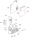
As an example, as shown in fig. 4 to 6, a dermocosmetic apparatus 1000 to which the iontophoresis device 100 according to the present invention is applied may include a housing portion 210, a frame portion 220, and a cap portion 230.
The housing part 210 may form an entire outer shape and includes a main body 211, and the main body 211 serves to accommodate various components such as the light source 300, the circuit board 242, and the known battery 110 serving as a power supply unit therein to protect the components from an external environment.
That is, the case part 210 may include a main body 211, and the main body 211 is provided in a box shape having a predetermined receiving space so as to receive various components. Also, the cap 230 may be detachably coupled to the body 211.
For example, the lower portion of the body 211 may be openly formed such that the various components are inserted into the accommodating space side, and the open lower portion is sealed by a cap 230 detachably coupled to the lower portion of the body 211.
At this time, two contact electrodes 121 and 122 for implementing an ion introduction function are provided on one side of the body 211 to be exposed to the outside, and a light transmitting member 212 for protecting the light source 300 from the external environment and protecting the eyes of the user may be provided on the front side of the light source 300.
For this, a seating surface 214 on which the two contact electrodes 121 and 122 are seated may be provided on one surface of the body 211, and the seating surface 214 may be formed in a hollow shape extending inward by a predetermined length from an upper edge of the body 211. In addition, the light-transmitting member 212 may be disposed in a hollow portion of the seating surface 214.
At this time, in the case part 210 described above, the main body 211, the two contact electrodes 121 and 122, and the light transmitting member 212 may be detachably connected, but may be integrally formed to increase assembly convenience and minimize the entry of foreign substances due to contact with the skin of the user during use.
For example, the main body 211, the two contact electrodes 121 and 122, and the light transmitting member 212 may be integrally formed, and as a specific example, they may be integrally formed by insert injection.
That is, the two contact electrodes 121 and 122 and the light-transmitting member 212 are integrated by one-time injection and ejection such that the two contact electrodes 121 and 122 are disposed on the outer edge side of the light-transmitting member 212 in a state of being physically separated from each other.
In this case, the light-transmitting member 212 may have a pair of insertion grooves 212a cut to a predetermined depth from an upper surface thereof, and the two contact electrodes 121 and 122 may be formed with extension portions 221a and 222a extending downward from outer edges thereof. Thereby, the extension parts 221a and 222a are disposed at the insertion groove 212a, so that the two contact electrodes 121 and 122 can be integrated with the light transmitting member 212.
Further, the main body 211 is formed by the second insert injection in a state where the light transmitting member 212 and the two contact electrodes 121 and 122 are integrated, so that the light transmitting member 212, the two contact electrodes 121 and 122, and the main body 211 can be integrated in a state where the two contact electrodes 121 and 122 are arranged on the mounting surface 214.
At this time, the light-transmitting member 212 and the main body 211 formed by insert injection may be made of a known thermoplastic resin. The thermoplastic resin used for forming the light transmitting member 212 and the thermoplastic resin used for forming the main body 211 may be the same material, but the melting point of the thermoplastic resin used for forming the light transmitting member 212 is relatively higher than the melting point of the thermoplastic resin used for forming the main body 211. This is to prevent the light-transmitting member 212 integrated with the two contact electrodes 121 and 122 by the primary burying injection from melting in the process of the secondary burying injection for integration with the main body 211.
For example, the light-transmitting member 212 may be made of a polymer material having a melting point of about 300 ℃, and the body 211 may be made of ABS resin having a melting point of about 1000 ℃. However, it is to be understood that the materials of the light-transmitting member 212 and the main body 211 described above are not limited thereto, and may be made of any known thermoplastic resin having different melting points and capable of being injected.
On the other hand, the two contact electrodes 121, 122 may be formed of a plate-shaped member having a predetermined area so as to enlarge a contact area with the skin, and may be provided wholly or partially on the seating surface 214.
Further, the outer edge sides of the two contact electrodes 121 and 122 connected to the extension portions 221a and 222a may be formed as curved surfaces. Accordingly, in the process of wiping the skin of the user by contacting the two contact electrodes 121 and 122 with the skin of the user, the skin of the user can be prevented from being damaged by the sharp edges or the ionic medicine or foreign substances existing in the skin can be prevented from being scraped by the edges.
At this time, the seating surface 214 may be formed as an inclined surface having a predetermined inclination with respect to a horizontal plane. As an example, as shown in fig. 4, the seating surface 214 may include an inclined surface having a height relatively lower than a height of a right side with respect to a left side of the bottom surface of the case part 210, and the two contact electrodes 121 and 122 may be disposed on the inclined surface.
Thereby, the two contact electrodes 121, 122 arranged at the above-described inclined surfaces may also be arranged to have a predetermined inclination with respect to the horizontal plane. Thereby, the contact area of the skin in contact with the two contact electrodes 121, 122 can be increased when in contact with the skin of the user. Also, during use, even if the wrist is not excessively bent in a state where the user grips the body 211 so that the two contact electrodes 121, 122 are brought into contact with the skin, natural contact between the skin of the user and the contact electrodes 121, 122 can be achieved.
In this case, the entire seating surface 214 may be formed as an inclined surface, or a part of the seating surface 214 may be formed as an inclined surface.
The frame part 220 is disposed in the inner space of the main body 211, and fixes the circuit board 242 on which the light source 300 is mounted, so that the light source 300 can be located at a region corresponding to the light-transmitting member 212 when the cap part 230 and the case part 210 are combined.
To this end, the frame part 220 may include an upper plate frame 121, and the circuit board 242 may be detachably coupled to the upper plate frame 121.
The upper frame 121 may be a frame structure having an open interior or may be a plate-shaped member.
Thus, the circuit board 242 may be fixed to the frame part 220 by a fastening member such as a bolt member, and in a state where the lower side of the frame part 220 is fixed to the cap part 230, if the cap part 230 and the housing part 210 are fastened, the light source 300 mounted on the circuit board 242 may be located in a region corresponding to the light-transmitting member 212.
Among them, an insulating member 245 for electrical insulation between the circuit board 242 and the upper board frame 121 may be disposed between the circuit board 242 and the upper board frame 121.
At this time, the frame part 220 may include at least one support frame 122 extending downward from the upper plate frame 121, and a lower end side of the support frame 122 may be detachably coupled to the cap part 230.
Specifically, the support frame 122 may be provided with at least one coupling member 223, the coupling member 223 may be fastened to the cap 230, and a coupling hole 231 may be formed through the cap 230 at a position corresponding to the coupling member 223.
At this time, the coupling member 223 may include a cut-out piece 225, the cut-out piece 225 may be formed by cutting a portion of the coupling member 223 and may be elastically deformable, and the cut-out piece 225 may be formed such that one end side thereof protrudes outward from one surface of the coupling member 223.
Accordingly, when the cut-off member 225 and the cap 230 are coupled, the cut-off member 225 is inserted into the coupling hole 231 by elastic deformation caused by an external force and returns to an original state to be caught at an edge side of the coupling hole 231, so that it can be prevented from being separated from the coupling hole 231.
The cut-out part 225 may be formed on the central portion side of the coupling part 223 or may be formed on the side end portion side of the coupling part 223.
In this case, a catching groove 232 may be formed on a lower surface of the cap 230, the catching groove 232 may be formed to have a predetermined depth from a lower surface of the cap 230 so as to be connected to the coupling hole 231, and an end of the cut-out 225 passing through the coupling hole 231 may be caught in the catching groove 232 when the frame part 220 is coupled thereto.
Accordingly, when the cap 230 and the frame 220 need to be reassembled or separated, the cut-out member 225 exposed to the locking groove 232 is pressed by a tool such as a screwdriver, so that the cap 230 and the frame 220 can be easily separated.
Thus, when the cap 230 and the frame 220 need to be reassembled or separated, the cut-out member 225 is elastically deformed by applying an external force to the cut-out member 225, so that the holding force of the cut-out member 225 can be released. Accordingly, the cut-off member 225 passes through the coupling hole 231 in a state of being elastically deformed by an external force, so that the cap 230 and the frame 220 can be separated.
Wherein the support frame 122 may be provided as a pair of frames extending downward from both side ends of the upper plate frame 121, and a pair of vertical bars 122a having a predetermined length and extending from the side ends of the upper plate frame 121 may be connected to each other by at least one support bar 122 b.
On the other hand, the support frame 122 includes at least one protrusion rod 226, and the protrusion rod 226 protrudes from the main body to the inner space by a predetermined length such that the battery 110 disposed inside the frame part 220 can be restricted from moving upward when the cap part 230 and the frame part 220 are combined.
For example, the protruding rod 226 may extend inward from the supporting rod 122b by a predetermined length, and the upper surface of the battery 110 may contact the lower surface of the supporting rod 122 b.
On the other hand, in the case where the two contact electrodes 121 and 122 for performing the ion introduction function are disposed on one surface of the case part 210, the two contact electrodes 121 and 122 may be electrically connected to the circuit board 242 on which the light source 300 is mounted by a contact method using a pair of elastic members 243 when the cap part 230 and the case part 210 are combined.
Thereby, the above-described contact electrodes 121, 122 apply galvanic current to the body of the user using the electric power supplied through the battery 110, so that the skin of the user and the two contact electrodes 121, 122 constitute a closed circuit.
For this, the elastic member 243 may be formed of a material having conductivity and elasticity.
As a specific example, the elastic member 243 may include a first portion 234a mounted on the circuit board 242 and a second portion 243b inclined at a predetermined angle from an end of the first portion 234a, and at least a portion of the second portion 243b may be disposed between the circuit board 242 and the contact electrodes 121 and 122 in contact with lower surfaces of the contact electrodes 121 and 122.
Thus, after the frame portion 220 to which the circuit board 242 is fixed to the cap portion 230, the cap portion 230 and the case portion 210 are joined to each other, so that the second portion 243b can be held in close contact with the corresponding contact electrodes 121 and 122. Thereby, the two contact electrodes 121 and 122 and the circuit board 122 fixed to the frame portion 220 can be electrically connected to each other through the elastic member 243.
That is, in the skin beauty apparatus 1000, the contact electrodes 121 and 122 and the circuit board 242 are electrically connected to each other by the close contact using the elastic member 243 without a separate wire connection work or a wire connection work for electrically connecting the circuit board 242 and the two contact electrodes 121 and 122, and thus, the working process can be simplified and the assemblability can be improved.
The mounting surface 214 may include a through hole 215 having an elongated hole, and the through hole 215 may be formed to penetrate so as to be closely attached to the contact electrodes 121 and 122 through the second portion 243b of the elastic member 243. Further, although it is illustrated in the drawings that the above-described elastic member 243 is linear, the present invention is not limited thereto, and the above-described elastic member 243 may have a predetermined width so as to increase a contact area.
On the other hand, at least one protruding rib 216 protruding inward in the height direction may be provided on the inner side surface of the above-described main body 211. When the cap part 230 and the case part 210 are coupled, the protruding ribs 216 may apply pressure to a side portion of the circuit board 242 fixed to the upper board frame 121 of the frame part 220 so that the circuit board 242 is aligned directly below the light-transmitting member 212.
Accordingly, in the case where the plurality of light sources 300 are mounted on the circuit board 242, an imaginary center line of the circuit board 242 may be positioned directly below an imaginary center line of the light-transmitting member 212 when the cap part 230 and the case part 210 are assembled.
Thereby, even if the light sources 300 are disposed at predetermined intervals from the lower surface of the light transmitting member 212, light generated from the respective light sources 300 may be emitted to the outside at an initially designed irradiation angle.
For example, the protruding rib 216 is provided to have a thickness that protrudes inward from a lower portion to an upper portion along the height direction of the body 211, so that the side portion of the circuit board 242 can be gradually pressed in the process of inserting the frame portion 220 fastened to the cap portion 230 into the inner space side.
The cap part 230 is formed to seal one side of the inner space of the case part 210.
The cap 230 may be formed integrally with the housing 210, or may be detachably connected to the housing 210.
For example, a plurality of hooks 233 for fastening to the body 211 may be formed at a predetermined height on an outer edge side of the cap 230, and fastening grooves 217 having a stepped structure may be formed on an inner surface of the body 211, respectively, such that ends of the hooks 233 are inserted into positions corresponding to the hooks 233 and are hooked.
Accordingly, when the cap 230 is coupled to the body 211, the ends of the hooks 233 are inserted into the fastening grooves 217, so that the ends of the hooks 233 are caught by the fastening grooves 217, thereby preventing the cap 230 from being separated from the body 211.
Thus, the skin care device 1000 can be assembled by integrally forming the light transmitting member 212, the contact electrodes 121 and 122, and the main body 211 to form the housing portion 210, inserting the frame portion 220 to which various components are fastened into the inner space of the housing portion 210, and then fastening the cap portion 230 to the main body 211.
In which at least one fastening hole 234 through which a fastening member such as a bolt member passes is formed through the cap 230 to increase a coupling force with the case part 210, so that the cap 230 can be fastened to the case part 210 by the fastening member.
Further, the above cap part 230 can be detachably attached to the framing part 220 for fixing the circuit board 242 on which the light source 300 is mounted.
For example, a coupling hole 231 is formed through the cap 230 at a position corresponding to the coupling member 223 such that when the cut member 225 formed at one end of the frame part 220 is coupled to the cap 230, the cut member 225 is inserted into the coupling hole 231 by elastic deformation caused by an external force and returns to an original state to be caught at an edge of the coupling hole 231.
A catching groove 232 is formed on the lower surface of the cap 230, and the catching groove 232 is formed to have a predetermined depth from the lower surface of the cap 230 to be connected to the coupling hole 231 such that the cut-off member 225 is exposed to the catching groove 232 side. Accordingly, when it is necessary to re-assemble or separate the cap part 230 and the frame part 220, the cut-away piece 225 exposed to the catching groove 232 is pressed using a tool such as a screwdriver, so that the cut-away piece 225 can pass through the coupling hole 231, and thus, the cap part 230 and the frame part 220 can be separated from each other.
On the other hand, the cap 230 may fix a main circuit board 244 constituting the control unit 130, and may also fix a circuit board 144 constituting the switch unit 140 for sensing an operation signal of a user.
The battery 110 may be disposed on one surface of the main circuit board 244, and the circuit board 242 on which the battery 110, the main circuit board 244, and the light source 300 are mounted and the circuit board 144 constituting the switching unit 140 may be electrically connected to each other.
As a specific example, at least one fixing rib 235 for fixing the main circuit board 244 may be formed at the cap part 230 with a predetermined height.
That is, the fixing ribs 235 may be provided as a pair of ribs arranged at a predetermined interval on the upper surface of the cap part 230, and the main circuit board 244 may be fixed to the pair of fixing ribs 235 by a fastening member such as a bolt member.
Wherein, when the frame part 220 and the cap part 230 are combined, the battery 110 may be disposed at a side directly below the upper board frame 221, and may be disposed between the pair of support frames 222.
That is, when the cap part 230 and the frame part 220 are coupled, one surface of the battery 110 may be in contact with the main circuit board 244, the upper end of the battery 110 may be in contact with the protruding rod 226, and the lower end of the battery 110 may be in contact with the upper surface of the cap part 230.
At this time, the buffer member 249 having a predetermined area is disposed between the support frame 222 and the battery 110 in such a manner as to be in contact with the battery 110 and the support frame 222, respectively, and thus, it is possible to prevent the flow of the battery 110 and to absorb the impact generated from the outside. In addition, a separate buffer member 249 may be further provided between the lower surface of the battery 110 and the upper surface of the cap 230.
Also, at least one support rib 236 for supporting the circuit board 144 constituting the switch unit 140 for sensing the operation signal of the user may be formed at the cap part 230 at a predetermined height.
As an example, the support ribs 236 may be provided as a pair of ribs arranged at a predetermined interval on the upper surface of the cap 230, and the pair of support ribs 236 may be formed with guide grooves 237 cut out in a height direction from an upper end thereof for insertion of both side segments of the circuit board 144.
As described above, since the cap 230 is fastened to the frame part 220, the battery 110 as a power supply source, the main circuit board 244, the circuit board 144 of the switch unit 140, and the like, the skin beauty apparatus 1000 can be easily assembled.
That is, in a state where the frame part 220, the battery 110, the main circuit board 244, and the circuit board 144 of the switch unit 140 are all coupled to the cap part 230, when the cap part 230 and the case part 210 are fastened, assembly can be completed.
Wherein a separate final member 238 for preventing the coupling hole 231 and the catching groove 232 from being exposed to the outside may be attached to the lower surface of the cap 230.
On the other hand, the above-described light source 300 generates light having a predetermined wavelength band and irradiates the light to the skin side of the user, so that it is possible to obtain an inherent advantageous effect that the user can obtain in the wavelength band of the light.
At this time, the above-described skin beauty apparatus 1000 can be implemented to obtain each inherent effect obtained at different wavelength bands by one device.
For this, the light source 300 may be configured to be capable of irradiating light of different wavelength bands. For example, the light source 300 may be configured by a plurality of light sources having light of different wavelength bands, or may be configured by integrally forming a plurality of light emitting elements 331, 332, and 333 for emitting light of different wavelength bands with one light source 300 (see fig. 5 and 15).
That is, the light source 300 may be implemented in a single package form by mounting a plurality of light emitting elements that irradiate light of different wavelength bands on one substrate. As an example, the light source 300 may include an LED device as the light emitting element, and a plurality of LED devices irradiating light of different wavelength bands may be used as the plurality of light emitting elements to realize a single LED package.
As a specific example, the plurality of light emitting elements may include: a first light emitting element 331 which irradiates light having an arbitrary wavelength in a 400 to 480nm wavelength band; a second light emitting element 332 for emitting light having an arbitrary wavelength within a wavelength range of 550 to 610 nm; and a third light emitting element 333 for emitting light of an arbitrary wavelength within a wavelength range of 610 to 650 nm.
Thus, the user operates by selecting any one of the first light emitting element 331, the second light emitting element 332, and the third light emitting element 333 constituting the above-described light source 300, and thus effects such as calming the skin, improving the skin texture, calming sensitive skin, improving the skin profile, improving the skin elasticity, restoring the skin elasticity, improving the skin lift, and improving the skin luster can be obtained by one light source.
For this, as shown in fig. 15 to 17, the light source 300 may include a mold 310, a plurality of connection electrodes 321 and 322, a plurality of light emitting elements 331, 332 and 333, and a sealing material 340.
The mold body 310 is used to form a light source in a single structure by molding a plurality of light emitting elements 331, 332, 333 and a plurality of connection electrodes 321, 322.
That is, the mold body 310 may integrally mold the plurality of light emitting elements 331, 332, 333 and the plurality of connection electrodes 321, 322 using a single material.
The mold body 310 may be formed of a mold material known in the art. The mold body 310 may be made of silicon, silicon oxide, and various transparent resins, for example.
At this time, the mold body 310 may be formed with a receiving portion 312 that enters a predetermined depth from an upper surface.
The accommodating part 312 provides a space for accommodating the plurality of light emitting elements 331, 332, and 333, and an inner side surface thereof is formed as an inclined surface inclined from an upper portion toward a lower portion at a predetermined angle, so that an emission angle of light generated from the plurality of light emitting elements 331, 332, and 333 can be controlled.
On the other hand, a reflective material having excellent light reflection efficiency may be coated on the inclined surface at a predetermined thickness to improve light efficiency by reflecting light generated when the plurality of light emitting elements 331, 332, 333 emit light.
The plurality of connection electrodes 321 and 322 and the plurality of light emitting elements 331, 332, and 333 are electrically connected to each other, and thus can be used as terminals for supplying power supplied from the outside of the light source 300 to the plurality of light emitting elements 331, 332, and 333.
That is, at least a portion of the plurality of connection electrodes 321 and 322 is exposed to the outside of the mold 310 to be electrically connected to the electrode pattern of the circuit board 242 on which the light source 300 is mounted, so that it can receive power required by the plurality of light emitting elements 331, 332, and 333.
To this end, the plurality of connection electrodes 321 and 322 may include a first electrode 321 and a second electrode 322 to which power of different polarities is applied when power is supplied, respectively, and the first electrode 321 and the second electrode 322 may be integrated with the mold body 310 in such a manner that a portion thereof is exposed to the outside.
The first electrode 321 and the second electrode 322 may be formed of a conductive member having a predetermined length, and a portion of the entire length may be exposed to the bottom surface of the receiving portion 312, and a portion of the remaining length may be exposed to the outside of the mold body 310.
That is, as shown in fig. 16 and 17, the first and second electrodes 321 and 322 are formed to have a substantially "ㄷ" shape and may be integrated with the mold body 310 such that portions of the first and second electrodes 321 and 322 are exposed to the bottom surface of the receiving portion 312 and the outer surface of the mold body 310, respectively.
Thus, the first and second electrodes 321 and 322 are electrically connected to the light emitting elements 331, 332, and 333 through first portions 321a and 322a exposed to the bottom surface of the receiving portion 312, and are electrically connected to the circuit board 242 through second portions 321b and 322b exposed to the outside of the mold body 310.
Although it is shown that the second portions 321b and 322b of the conductive member constituting the first and second electrodes 321 and 322 are exposed to the side and lower surfaces of the mold body 310, the present invention is not limited thereto, and the second portions 321b and 322b may be exposed only to the lower surface of the mold body 310 or may be exposed only to the side of the mold body 310.
At this time, the light source 300 may include a plurality of first electrodes 321 and second electrodes 322 to which power of different polarities are respectively applied when power is supplied, and the number of the plurality of first electrodes 321 and second electrodes 322 may be a number that matches one another one-to-one.
Thus, a plurality of light emitting elements 331, 332, 333 having different characteristics (e.g., wavelengths) may be included in one light source 300, so that desired various characteristics can be achieved by one light source 300. This will be explained in detail below.
When the first and second electrodes 321 and 322 are respectively provided in plurality, the respective second portions 321b and 322b of the plurality of first and second electrodes 321 and 322 may be disposed to be exposed to different surfaces of the mold body 310, and the plurality of first portions 321a and 322a formed at the bottom surface of the receiving portion 312 may have the same or different shapes.
As an example, the respective second portions 321b of the plurality of first electrodes 321 may be disposed to be positioned on right and lower sides of the mold body 310, and the respective second portions 322b of the plurality of second electrodes 322 may be disposed to be positioned on left and lower sides of the mold body 310.
Accordingly, the positions of the first electrode 321 and the second electrode 322, to which power of different polarities is applied at the time of power supply, are clearly distinguished, so that it is possible to prevent wrong polarity connection in advance in a process in which a worker mounts the light source 300 on the circuit board 242.
At this time, at least one display portion 316 may be formed on an upper surface of the mold 310, so that a worker may more easily distinguish polarities of the first and second electrodes 321 and 322. For example, the display portion 316 may be a cut portion formed by cutting an edge of the mold body 310. However, the display portion 316 is not limited thereto as long as it can be easily recognized by a worker, for example, a color, a guide line label, and the like.
On the other hand, a seating groove 318 may be formed inwardly into a predetermined depth in a bottom surface of the mold body 310, and a portion of the second portion 321b, 322b may be disposed in the seating groove 318.
The plurality of light emitting elements 331, 332, 333 may function as light emitting sources for generating light having a predetermined wavelength band when power is supplied. That is, the plurality of light emitting elements 331, 332, 333 may generate light of a predetermined wavelength band for a skin improvement effect of a user. The light emitting elements 331, 332, and 333 can generate light of any wavelength band selected from the 400 to 970nm wavelength bands.
In this case, the plurality of light emitting elements 331, 332, and 333 may be provided as three light emitting elements that generate light in different wavelength bands. Each of the light emitting elements 331, 332, 333 may be individually mounted directly on any one of the plurality of first electrodes 321 and the plurality of second electrodes 322, respectively, and connected to the other electrodes paired with each other through wires 335.
That is, the respective light emitting elements 331, 332, 333 are directly mounted on the first portions 321a, 322a of any one of the first electrode 321 and the second electrode 322 exposed to the bottom surface of the receiving portion 312 to be electrically connected to the first electrode 321 or the second electrode 322, and are electrically connected to the first portions 321a, 322a of the other electrodes paired with each other through the wires 335.
Thus, when power is supplied, any one of the plurality of light emitting devices 331, 332, 333 is selectively operated, so that light of a wavelength band desired by a user can be selectively emitted.
For example, the plurality of light emitting elements 331, 332, 333 may be a first light emitting element 331 that irradiates light having an arbitrary wavelength in a 400 to 480nm wavelength band, a second light emitting element 332 that irradiates light having an arbitrary wavelength in a 550 to 610nm wavelength band, and a third light emitting element 333 that irradiates light having an arbitrary wavelength in a 610 to 650nm wavelength band.
Accordingly, the user operates by selecting any one of the first light emitting element 331, the second light emitting element 332, and the third light emitting element 333, so that effects such as calming the skin, improving the texture of the skin, calming sensitive skin, improving the contour of the skin, improving the elasticity of the skin, restoring the elasticity of the skin, improving the lift of the skin, treating wounds, relieving pain, treating acne, and improving the luster of the skin can be obtained by one light source 300.
The light emitting elements 331, 332, and 333 may be horizontal light emitting elements or vertical light emitting elements. Further, although it is explained in the drawings and the description that the light emitting elements 331, 332, 333 are directly mounted on any one of the first electrode 321 and the second electrode 322 described above and electrically connected to the other electrodes through the wire 335, the present invention is not limited thereto, and various types of electrical connection structures known in the art to which the present invention pertains may also be employed.
Further, the number and wavelength band of the light emitting elements applied to the light source 300 are not limited to the above, and an appropriate light emitting element capable of producing a wavelength suitable for a desired skin improvement effect may be used. Alternatively, each of the above-described light emitting elements may emit light of any different wavelength band selected within a wavelength band of 400 to 970nm, and two light emitting elements emitting light of different wavelength bands may be disposed to irradiate light of wavelength bands in which a part of the wavelength bands overlap with each other.
On the other hand, a protective element 334 for protecting the respective light emitting elements 331, 332, and 333 from static electricity may be attached to any of the first electrode 321 and the second electrode 322. The protective member 334 may be directly mounted on the first portion 322a exposed to the bottom surface of the receiving portion 312, and connected to the first portions 321a of the other electrodes mated with each other by wires 335, like the light emitting elements 331, 332, 333. As an example of the protection element 334, a known zener diode can be used. However, the protection element 334 is not limited thereto as long as it has a form capable of protecting a circuit from static electricity.
At this time, the respective light emitting elements 331, 332, 333 that emit light of different wavelength bands are set to emit different amounts of light according to the wavelength bands used.
For example, among the plurality of light emitting elements 331, 332, 333, the light emitting element 331 having a wavelength band smaller than 500nm is set to emit a relatively smaller amount of light than the light emitting elements 332, 333 having a wavelength band equal to or larger than 500 nm.
Specifically, a light emitting element having a wavelength band of less than 500nm may have a luminous flux of 6 lumens (lm) or less, and a light emitting element having a wavelength band of 500nm or more may have a luminous flux of 8 lumens (lm) or less.
That is, the first light emitting element 331 emitting light in the 400 to 480nm band may emit light having a luminous flux of 6 lumens or less, the second light emitting element 332 emitting light in the 550 to 610nm band and the third light emitting element 333 emitting light in the 610 to 650nm band may emit light having a luminous flux of 8 lumens or less.
This is to prevent problems that a user feels discomfort due to heat generated from the respective light emitting devices 331, 332, 333 and harmful effects such as impairment of visual acuity due to light emitted from the respective light emitting elements 331, 332, 333 in case of body contact when the above-described light source 300 is applied to the skin beauty appliance 200 in contact with the user's body because the first light emitting element 331 having a relatively shorter wavelength generates relatively higher heat than the second light emitting element 332 and the third light emitting element 333 having a relatively longer wavelength.
That is, in the present invention, luminous fluxes emitted from the respective light emitting elements 331, 332, 333 are controlled by the control unit 130 so as to emit light with a luminous flux of 8 lumens or 6 lumens or less according to the wavelength bands of the light emitting elements 331, 332, 333, and thus, the light emitting elements may be set so that a temperature of 40 ℃ or less similar to a temperature of a human body may be generated when the light emitting elements emit light.
The sealing material 340 may be a resin material filled in the housing 312 so as to cover and protect the light emitting elements 331, 332, 333 and the conductive wire 335 disposed in the housing 312.
The sealing material 340 as described above may be a transparent resin that emits the color of light generated from the light emitting elements 331, 332, 333 arranged in the above-described housing portion 312 as it is, or may be a transparent resin including phosphors that convert the wavelength of light generated at the above-described light emitting elements 331, 332, 333 and emit in other colors.
At this time, a protrusion 314 protruding at a predetermined height along an edge of the receiving portion 312 may be formed on an upper surface of the mold body 310. The protrusion 314 as described above serves to prevent the sealing material 340 filled in the receiving portion 312 from overflowing or being lost through the opened upper portion of the receiving portion 312 during a curing process in a process of manufacturing the light source 300.
However, it is to be understood that the type of the light source described above is not limited thereto, and an appropriate light source capable of producing a wavelength suitable for a desired skin improvement effect may be used.
For example, the light emitting elements 331, 332, and 333 may emit light in any of different wavelength bands selected from the wavelength bands of 400 to 970nm, and two different light emitting elements may be arranged to emit light in wavelength bands in which some of the wavelength bands overlap with each other.
The light source may be a single light emitting element that emits light in a predetermined wavelength band within a wavelength band of 400 to 970 nm. In this case, as the light source, two or more light sources that irradiate light of different wavelength bands may be suitably used.
The light source may be continuously turned on or repeatedly turned on and off.
On the other hand, when the light source 300 includes a plurality of light emitting elements for emitting light of different wavelength bands, the selection of the light emitting mode of the light source 300 may be performed by the operation of the switching unit 140 provided at one side of the housing part 210, and the driving thereof may be controlled by the control unit 130.
As shown in fig. 4, the switch unit 140 may include at least one button 142 and a circuit board 144, the at least one button 142 is exposed to one side of the housing part 210, the circuit board 144 is disposed inside the housing part 210 and has a circuit part generating a signal corresponding to an operation of the button 142, and the circuit board 144 may be electrically connected to the main circuit board 134 constituting the control unit 130.
For example, the switch unit 140 may be a known tact switch, and the first light emitting mode, the second light emitting mode, and the third light emitting mode may be sequentially changed by the driving of the control unit 130 based on the number of times the user presses the button 142, or the strong mode, the normal mode, and the weak mode may be switched. The present invention is not limited thereto, and an operation of turning on and off the entire driving of the beauty instrument may be implemented in addition to an operation of selecting a light emitting mode or an intensity mode of the light source at the time of the operation of the above-described button 142.
The control unit 130 may include a timer function for cutting off power supplied to the light emitting elements 331, 332, and 333 after a predetermined time elapses while the light emitting elements 331, 332, and 333 are continuously operated.
The light source 300 as described above may be mounted in a predetermined pattern on the circuit board 242 fixed to the upper board frame 221 of the frame part 220, and may be disposed at a lower side of the light-transmitting member 212 when the cap part 230 and the housing part 210 are combined.
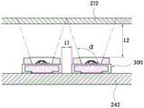
At this time, one side of the light source 300 may be disposed to be in contact with the light-transmitting member 212, or may be disposed to be spaced apart from one surface of the light-transmitting member 212 by a predetermined interval. Further, when the light source 300 is provided in plurality, the plurality of light sources 300 may be disposed at the same interval from the light-transmitting member 212, or may be disposed at different intervals from the light-transmitting member 212.
As a specific example, when the light sources 300 are provided in plurality and the respective light sources 300 are disposed at predetermined intervals from the light-transmitting member 212, the interval distance L1 between the adjacent light sources 300 and the interval distance L2 from the respective light sources 300 to the light-transmitting member 212 may satisfy the following formula 1.
Mathematical formula 1
When the spaced distance from each light source 300 to the light-transmitting member 212 is 1.6 times or less the spaced distance from each adjacent light source 300 to the light-transmitting member 212, the lights emitted from each light source 300 and reaching the above-described light-transmitting member 212 do not overlap with each other, so that attenuation or loss of light due to superposition may not occur.
Thereby, the advantageous effects that the user needs to obtain in the predetermined wavelength band can be obtained by preventing the reduction of the amount of light generated by each light source 300 in advance, and all the problems due to heat generation can be solved since light can be emitted at a luminous flux of 8 lumens or 6 lumens or less.
As described above, the above-described dermocosmetic apparatus 200 can simultaneously use the plurality of light emitting elements 331, 332, 333 that emit light of different wavelength bands by limiting the spacing distance between the light sources 300 and the light transmitting member 212 to a predetermined range, and can achieve a desired light distribution even if the plurality of light sources 300 are arranged.
On the other hand, when the light source 300 is disposed with a predetermined interval from the light transmitting member 212 by the combination of the cap part 230 and the housing part 210, the light source 300 may be disposed directly below an area corresponding to the transparent member 212. Thus, in the skin beauty apparatus 1000 of the present invention, the light sources 300 generating light are disposed at a predetermined interval on the lower side of the light-transmitting member 212 in a state of being accommodated in the housing part 210, so that the emission angle of light emitted to the outside can be restricted.
That is, light emitted from the above-described light source 300 is emitted through the light-transmitting member 212 arranged in the hollow portion of the above-described seating surface 214 in a relatively narrow angle range compared with the irradiation angle of the light source itself.
Thereby, even if the light source 300 is operated in a state of being close to the skin of the user, particularly, the face of the user, the light generated from the light source 300 can be emitted in a narrow range toward the skin side to be treated, so that the light can be prevented from entering the eyes of the user.
At this time, the light source 300 may be turned on only when the distance between the light source 300 and the skin is within a predetermined range, and the light source 300 may be turned off when the distance between the light source 300 and the skin is beyond the predetermined range.
This is to prevent the light emitted from the light source 300 from being directly irradiated to the eyes of the user even if the above-described light-transmitting member 212 side faces the eyes of the user regardless of the intention of the user during use, thereby preventing the eyes of the user from being damaged by the light in advance.
For this, at least one proximity sensor 246 may be provided on the circuit board 242 on which the light source 300 is mounted, and the proximity sensor 246 may control the light on and off of the light source 300 by sensing a distance between the light source 300 and the skin.
The proximity sensor 246 may be provided in plural, may be disposed between adjacent light sources 300, or may be disposed outside the outermost light source 300.
Further, the light source 300 may be initially turned on only when the two contact electrodes 121 and 122 are all in contact with the skin of the user and the distance between the light source 300 and the skin is within a predetermined range.
This is to control initial lighting of the light source 300 by sensing whether or not contact with the skin of the user is made even if the distance between the light source 300 and the skin is located at an approach distance within a predetermined range in the process that the user moves to the body part to be cared for, so that initial lighting can be achieved in a state where the user finally moves to a correct position to be cared for. Thereby, the light source 300 can be prevented from suddenly operating regardless of the intention of the user.
On the other hand, the light-transmitting member 212 is formed integrally with the body 211 and is disposed in front of the light source 300, thereby protecting the light source 300 from the external environment and protecting the eyes of the user from the light emitted to the outside when the light source 300 is turned on. In addition, the light-transmitting member 212 may also perform a function of improving the diffusivity of light generated from the light source 300 so that the light is uniformly emitted to the outside.
For this, the light-transmitting member 212 may have a predetermined transmittance so as to reduce the intensity of light generated from the light source 300 and emitted to the outside. In addition, the light-transmitting cover 140 may contain a component for diffusing light so that the light is uniformly emitted to the outside.
For example, the light-transmitting member 212 may have a transmittance of 70 to 90%, and preferably, a light-diffusing PC having a transmittance of 70 to 90% may be used. Although the light-transmitting member 212 has a transmittance of 70 to 90%, the present invention is not limited thereto, and the transmittance may be appropriately adjusted as long as the light diffusibility of light can be enhanced while protecting the eyes of the user.
Also, the body 211 may include a light blocking material, so that light generated at the light source 300 may be blocked from being emitted to the outside through the body 211. The light-shielding material may be a known black resin or black pigment, but is not limited thereto, as long as it can prevent the light leakage phenomenon by blocking light, and can simultaneously achieve the electromagnetic wave shielding property and the light-shielding effect by including metal components such as chromium (Cr), gold (Au), silver (Ag), copper (Cu), and platinum (Pt).
On the other hand, the skin beauty apparatus 1000 may include a control unit which controls the entire driving by processing a light emitting pattern change of the light source based on the operation of the button 142, supply/blocking of the power source, on/off of the light source, information obtained by the proximity sensor 246, and the like.
The control unit may be the control unit 130 used in the iontophoresis device 100, and the control unit 130 may include a light emission mode change of the light source, power supply/shutoff, on/off of the light source, an information processing function by the proximity sensor 246, and a timer function, which are based on the operation of the button 142.
Further, the above-described control unit may store a lookup table (lookup table) for adjusting the operating state and output intensity of the light source 300 or appropriately adjusting the magnitude of the direct current applied to the contact electrodes 121, 122 according to the distance between the skin and the light source 300 obtained by the proximity sensor 246.
The skin care device 1000 may further include a notification unit that is linked to the operation of the button 142. The driving of the notification unit is controlled by the control unit when the user operates the button 142, so that the user can easily recognize whether the button 142 is operated. For example, the notification means may be a vibration tool 247 electrically connected to the circuit board 242, or may be a sound output tool (not shown) such as a speaker for outputting sound to the outside. The vibration tool 247 may be a vibration motor or a vibration sensor.
That is, when the user presses the button 142, the control unit recognizes the operation of the button 142 through a signal transmitted from the circuit board 144 disposed at the rear side of the button 142, causes the notification unit to be driven, thereby enabling the vibration tool 247 to vibrate for a predetermined time or output a sound to the outside. Thus, the user can easily recognize the turning on and off of the power source and the change of the light emitting mode of the light source by the operation of the button 142, and can correctly switch to a desired mode.
Wherein the output mode of the notification unit may be different according to each light emitting mode. As an example, in the case of a vibration mode occurring by the vibration tool 247, at least one of the intensity of vibration and the duration of vibration may be output in different modes when selecting or converting to the first, second, and third light emitting modes, and when outputting sound through a speaker, inherent sound may be output to the outside according to each mode.
On the other hand, the skin beauty apparatus 1000 may include a cover 250, and the cover 250 may be detachably coupled to the case part 210 so as to protect the two contact electrodes 121 and 122 and the light transmitting member 212 exposed to the outside at the upper side of the case part 210 from the external environment.
In addition, the beauty treatment apparatus 1000 may include a charging terminal 248 exposed to the outside at one side of the housing part 210. Thereby, the battery disposed inside the case part 210 can be easily charged.
The charging terminal 248 may be electrically connected to the main circuit board 244 to charge the battery by using power from the outside.
Although it is exemplified that the iontophoresis device 100 according to the present invention is applied to the above-described dermopharmaceutical apparatus 1000, the structure of the above-described dermopharmaceutical apparatus 1000 is not limited thereto, and the structures of various known dermopharmaceutical apparatuses including the light source 300 may be suitably employed.
The two contact electrodes 121 and 122 constituting the iontophoresis device 100 may be realized in a bipolar manner disposed on the same surface of the housing 210 at a distance from each other, or may be realized in a manner disposed at different positions of the two contact electrodes 121 and 122.
Further, in the case of the light source 300 described in the above-described embodiment, it may be suitably applied to the structure of various known dermocosmetic instruments including the light source 300, or may also be separately applied to known dermocosmetic instruments that do not use an iontophoresis function, in addition to the above-described dermocosmetic instrument 1000.
While the embodiments of the present invention have been described above, the gist of the present invention is not limited to the embodiments of the present invention, and those skilled in the art can easily propose other embodiments by adding, modifying, deleting, adding, etc. components within the same gist of the present invention, and these embodiments fall within the gist of the present invention.