[go: up one dir, main page]

CN109285974B - Secondary battery top cover assembly and secondary battery - Google Patents

Secondary battery top cover assembly and secondary battery Download PDF

Info

Publication number
CN109285974B
CN109285974B CN201710599686.4A CN201710599686A CN109285974B CN 109285974 B CN109285974 B CN 109285974B CN 201710599686 A CN201710599686 A CN 201710599686A CN 109285974 B CN109285974 B CN 109285974B
Authority
CN
China
Prior art keywords
pole
top cover
secondary battery
piece
contact piece
Prior art date
Legal status (The legal status is an assumption and is not a legal conclusion. Google has not performed a legal analysis and makes no representation as to the accuracy of the status listed.)
Active
Application number
CN201710599686.4A
Other languages
Chinese (zh)
Other versions
CN109285974A (en
Inventor
陈柏松
王鹏
吴凯
王志宇
陈小波
朱涛声
Current Assignee (The listed assignees may be inaccurate. Google has not performed a legal analysis and makes no representation or warranty as to the accuracy of the list.)
Contemporary Amperex Technology Co Ltd
Original Assignee
Contemporary Amperex Technology Co Ltd
Priority date (The priority date is an assumption and is not a legal conclusion. Google has not performed a legal analysis and makes no representation as to the accuracy of the date listed.)
Filing date
Publication date
Application filed by Contemporary Amperex Technology Co Ltd filed Critical Contemporary Amperex Technology Co Ltd
Priority to CN201710599686.4A priority Critical patent/CN109285974B/en
Priority to US15/950,617 priority patent/US10770696B2/en
Publication of CN109285974A publication Critical patent/CN109285974A/en
Application granted granted Critical
Publication of CN109285974B publication Critical patent/CN109285974B/en
Active legal-status Critical Current
Anticipated expiration legal-status Critical

Links

Images

Classifications

    • HELECTRICITY
    • H01ELECTRIC ELEMENTS
    • H01MPROCESSES OR MEANS, e.g. BATTERIES, FOR THE DIRECT CONVERSION OF CHEMICAL ENERGY INTO ELECTRICAL ENERGY
    • H01M50/00Constructional details or processes of manufacture of the non-active parts of electrochemical cells other than fuel cells, e.g. hybrid cells
    • H01M50/50Current conducting connections for cells or batteries
    • H01M50/572Means for preventing undesired use or discharge
    • H01M50/574Devices or arrangements for the interruption of current
    • H01M50/581Devices or arrangements for the interruption of current in response to temperature
    • HELECTRICITY
    • H01ELECTRIC ELEMENTS
    • H01MPROCESSES OR MEANS, e.g. BATTERIES, FOR THE DIRECT CONVERSION OF CHEMICAL ENERGY INTO ELECTRICAL ENERGY
    • H01M50/00Constructional details or processes of manufacture of the non-active parts of electrochemical cells other than fuel cells, e.g. hybrid cells
    • H01M50/10Primary casings; Jackets or wrappings
    • H01M50/147Lids or covers
    • H01M50/148Lids or covers characterised by their shape
    • H01M50/15Lids or covers characterised by their shape for prismatic or rectangular cells
    • HELECTRICITY
    • H01ELECTRIC ELEMENTS
    • H01MPROCESSES OR MEANS, e.g. BATTERIES, FOR THE DIRECT CONVERSION OF CHEMICAL ENERGY INTO ELECTRICAL ENERGY
    • H01M50/00Constructional details or processes of manufacture of the non-active parts of electrochemical cells other than fuel cells, e.g. hybrid cells
    • H01M50/50Current conducting connections for cells or batteries
    • H01M50/543Terminals
    • H01M50/547Terminals characterised by the disposition of the terminals on the cells
    • H01M50/55Terminals characterised by the disposition of the terminals on the cells on the same side of the cell
    • HELECTRICITY
    • H01ELECTRIC ELEMENTS
    • H01MPROCESSES OR MEANS, e.g. BATTERIES, FOR THE DIRECT CONVERSION OF CHEMICAL ENERGY INTO ELECTRICAL ENERGY
    • H01M50/00Constructional details or processes of manufacture of the non-active parts of electrochemical cells other than fuel cells, e.g. hybrid cells
    • H01M50/50Current conducting connections for cells or batteries
    • H01M50/543Terminals
    • H01M50/552Terminals characterised by their shape
    • H01M50/553Terminals adapted for prismatic, pouch or rectangular cells
    • HELECTRICITY
    • H01ELECTRIC ELEMENTS
    • H01MPROCESSES OR MEANS, e.g. BATTERIES, FOR THE DIRECT CONVERSION OF CHEMICAL ENERGY INTO ELECTRICAL ENERGY
    • H01M50/00Constructional details or processes of manufacture of the non-active parts of electrochemical cells other than fuel cells, e.g. hybrid cells
    • H01M50/50Current conducting connections for cells or batteries
    • H01M50/572Means for preventing undesired use or discharge
    • H01M50/574Devices or arrangements for the interruption of current
    • H01M50/578Devices or arrangements for the interruption of current in response to pressure
    • HELECTRICITY
    • H01ELECTRIC ELEMENTS
    • H01MPROCESSES OR MEANS, e.g. BATTERIES, FOR THE DIRECT CONVERSION OF CHEMICAL ENERGY INTO ELECTRICAL ENERGY
    • H01M50/00Constructional details or processes of manufacture of the non-active parts of electrochemical cells other than fuel cells, e.g. hybrid cells
    • H01M50/50Current conducting connections for cells or batteries
    • H01M50/572Means for preventing undesired use or discharge
    • H01M50/584Means for preventing undesired use or discharge for preventing incorrect connections inside or outside the batteries
    • H01M50/59Means for preventing undesired use or discharge for preventing incorrect connections inside or outside the batteries characterised by the protection means
    • H01M50/593Spacers; Insulating plates
    • HELECTRICITY
    • H01ELECTRIC ELEMENTS
    • H01MPROCESSES OR MEANS, e.g. BATTERIES, FOR THE DIRECT CONVERSION OF CHEMICAL ENERGY INTO ELECTRICAL ENERGY
    • H01M2200/00Safety devices for primary or secondary batteries
    • H01M2200/10Temperature sensitive devices
    • H01M2200/103Fuse
    • HELECTRICITY
    • H01ELECTRIC ELEMENTS
    • H01MPROCESSES OR MEANS, e.g. BATTERIES, FOR THE DIRECT CONVERSION OF CHEMICAL ENERGY INTO ELECTRICAL ENERGY
    • H01M2200/00Safety devices for primary or secondary batteries
    • H01M2200/20Pressure-sensitive devices
    • YGENERAL TAGGING OF NEW TECHNOLOGICAL DEVELOPMENTS; GENERAL TAGGING OF CROSS-SECTIONAL TECHNOLOGIES SPANNING OVER SEVERAL SECTIONS OF THE IPC; TECHNICAL SUBJECTS COVERED BY FORMER USPC CROSS-REFERENCE ART COLLECTIONS [XRACs] AND DIGESTS
    • Y02TECHNOLOGIES OR APPLICATIONS FOR MITIGATION OR ADAPTATION AGAINST CLIMATE CHANGE
    • Y02EREDUCTION OF GREENHOUSE GAS [GHG] EMISSIONS, RELATED TO ENERGY GENERATION, TRANSMISSION OR DISTRIBUTION
    • Y02E60/00Enabling technologies; Technologies with a potential or indirect contribution to GHG emissions mitigation
    • Y02E60/10Energy storage using batteries

Landscapes

  • Chemical & Material Sciences (AREA)
  • Chemical Kinetics & Catalysis (AREA)
  • Electrochemistry (AREA)
  • General Chemical & Material Sciences (AREA)
  • Connection Of Batteries Or Terminals (AREA)
  • Fuses (AREA)

Abstract

本申请涉及二次电池顶盖组件及二次电池。二次电池顶盖组件,包括:第一极柱、导电件、第二极柱以及顶盖片,所述顶盖片与所述第一极柱绝缘设置,所述顶盖片与所述第二极柱电连接,所述二次电池还包括接触片,所述接触片附接于所述顶盖片,所述导电件与所述顶盖片绝缘设置,所述导电件包括极柱连接部、第一熔断构件以及接触片连接部,所述第一熔断构件具有比所述极柱连接部和所述接触片连接部低的熔点,所述导电件还包括连接层,所述第一熔断构件经由所述连接层与所述极柱连接部连接,和/或,所述第一熔断构件经由所述连接层与所述接触片连接部连接。该方案提高了二次电池的安全性。

Figure 201710599686

The present application relates to secondary battery cap assemblies and secondary batteries. A secondary battery top cover assembly, comprising: a first pole, a conductive member, a second pole and a top cover piece, the top cover piece is insulated from the first pole pole, and the top cover piece is connected to the first pole piece. Diode poles are electrically connected, the secondary battery further includes a contact piece, the contact piece is attached to the top cover piece, the conductive member is insulated from the top cover piece, and the conductive piece includes a pole connection part, a first fuse member and a contact piece connecting part, the first fuse member has a lower melting point than the pole connecting part and the contact piece connecting part, the conductive member further includes a connection layer, the first The fuse member is connected to the pole connection portion via the connection layer, and/or the first fuse member is connected to the contact piece connection portion via the connection layer. This solution improves the safety of the secondary battery.

Figure 201710599686

Description

Secondary cell top cap subassembly and secondary cell
Technical Field
The application relates to the technical field of energy storage devices, in particular to a secondary battery top cover assembly and a secondary battery.
Background
Because the power battery (such as a lithium ion battery) has the advantages of high energy density, high power density, multiple recycling times, long storage time and the like, the power battery is widely used in portable electronic equipment such as mobile phones, digital cameras, portable computers and the like, has wide application prospects in large and medium-sized electric equipment such as electric vehicles such as electric automobiles, electric bicycles and the like, energy storage facilities and the like, and becomes a key for solving global problems such as energy crisis, environmental pollution and the like.
When the power battery is overcharged, the decomposition of the electrolyte in the power battery can increase the internal pressure of the power battery, so that the battery can catch fire and explode. In order to prevent ignition and explosion caused by an increase in internal pressure, an external short-circuiting unit is generally provided and a fuse is provided between the positive electrode tab and the positive electrode post. When the internal pressure of the power battery increases, the external short-circuiting unit short-circuits the positive and negative electrode tabs of the electrode assembly to form a large current to fuse the fuse disposed between the positive electrode tab and the positive post, thereby terminating the state of charge of the electrode assembly.
However, the above structure may reduce the capability of the power battery to cope with high temperature environment, for example, when the above structure is used for Hot Box (Hot-Box) test, the probability of thermal runaway of the power battery is greatly increased. The specific reason is as follows: in a high-temperature environment, the internal gas pressure in the power battery is increased along with the decomposition of the electrolyte at high temperature, and the internal resistance of the electrode assembly is also increased; at this time, if the external short-circuit unit causes the positive plate and the negative plate of the power battery to form a short circuit, the electrode assembly generates more heat due to the increase of the internal resistance and the presence of the short-circuit current, so that the risk of fire and explosion of the power battery is increased. In other words, the conventional external short circuit unit can only solve the overcharge problem of the power battery under normal temperature conditions, but can increase the thermal runaway probability under high temperature environment.
In order to reduce the thermal runaway probability of the secondary battery, in the related art, the secondary battery further includes a fusing member made of a low-melting-point alloy, and the fusing member is connected to the negative electrode conductive member, so that the fusing member can be fused to disconnect a short circuit loop when the secondary battery is subjected to a hot box test. However, when the connection strength between the fusing member and the negative electrode conductive member is low, the contact resistance between the fusing member and the negative electrode conductive member is high, so that the fusing member is fused when overcharged at normal temperature to form short-circuit current, and the problem of overcharging of the power battery at normal temperature after the fusing member is fused cannot be solved, thereby reducing the safety of the secondary battery.
Disclosure of Invention
The embodiment of the application provides a secondary battery top cover assembly, which can improve the safety of a secondary battery.
The application provides a secondary cell top cap subassembly includes: a first pole column, a conductive piece, a second pole column and a top cover plate,
the top cover plate is insulated from the first pole column and electrically connected with the second pole column,
the secondary battery further includes a contact piece attached to the top cover piece, the conductive member is arranged insulated from the top cover piece,
the conductive member includes a post connection portion, a first fuse member having a lower melting point than the post connection portion and the contact piece connection portion,
when the internal pressure of the secondary battery exceeds a reference pressure, the contact piece is deformed by the internal pressure and electrically connected with the contact piece connecting portion to form an electrical connection path through the first terminal and the second terminal,
the conductive piece further comprises a connecting layer, the first fusing member is connected with the pole connecting portion through the connecting layer, and/or the first fusing member is connected with the contact piece connecting portion through the connecting layer.
As an embodiment of the present application, the post connection portion and/or the contact piece connection portion are made of a first metal material, the first fuse member is made of a second metal material, the connection layer is made of a third metal material,
the joint force formed by the third metal material and the first metal material and the joint force formed by the third metal material and the second metal material are both larger than the joint force formed by the first metal material and the second metal material.
As an embodiment of the present application, the third metal material is nickel, a nickel alloy, tin, a tin alloy, bismuth, or a bismuth alloy, the first metal material is aluminum or an aluminum alloy, and the second metal material is a metal at least containing one or more elements of bismuth, tin, lead, zinc, or indium.
As an embodiment of the present application, the number of the connection layers is two, one of the connection layers is connected to the post connection portion, the other of the connection layers is connected to the first fuse member, and the two connection layers are welded.
As an embodiment of the present application, the present application further includes an insulating member, the conductive member is insulated from the top cover sheet by the insulating member,
the insulating member is provided with a first through hole through which the deformed contact piece passes to be in contact with the contact piece connecting portion.
As an embodiment of the present application, the insulating member includes a first portion and a second portion connected, the first portion being fixed between the pole connection portion and the top cover sheet, the second portion surrounding the periphery of the contact piece connection portion,
the first through hole is opened in the second portion.
The heat-insulating material further comprises a heat expansion part which is made of an insulating material and expands when heated,
the first fusing member and the thermal expansion part are arranged along the thickness direction of the conductive piece, the thermal expansion part is located above the first fusing member, and the thermal expansion part is respectively attached to the pole connecting part and the contact piece connecting part.
As an embodiment of the present application, the heat expansion part is provided with a heat insulation part, and the heat expansion part is arranged on the top cover plate.
The second aspect of the present application also provides a secondary battery including a secondary battery cap assembly, a case, and an electrode assembly, the secondary battery cap assembly being coupled to the opening of the case and forming an encapsulation space,
the electrode assembly comprises a first pole piece, a second pole piece and a partition plate arranged between the first pole piece and the second pole piece, wherein the first pole is electrically connected with the first pole piece, and the second pole is electrically connected with the second pole piece;
the electrode assembly is packaged in the packaging space, and the secondary battery top cover assembly is the secondary battery top cover assembly described in any one of the above.
As an embodiment of the present application, the battery further includes a second fuse member, the first terminal post is electrically connected to the first pole piece through the second fuse member,
and/or the presence of a gas in the gas,
the secondary battery further includes a third fusing member, and the second pole tab is electrically connected to the second pole tab through the third fusing member.
The technical scheme provided by the application can achieve the following beneficial effects:
the application provides a secondary cell top cap subassembly, including electrically conductive, electrically conductive including utmost point post connecting portion, first fusing component and contact piece connecting portion, the melting point of first fusing component is less than utmost point post connecting portion and contact piece connecting portion, in order to improve the risk of first fusing component and utmost point post connecting portion and the virtual connection of contact piece connecting portion, electrically conductive still includes the articulamentum, the articulamentum sets up on at least one of utmost point post connecting portion and contact piece connecting portion, first fusing component can be connected with utmost point post connecting portion via the articulamentum, perhaps be connected with contact piece connecting portion via this articulamentum, again perhaps, the articulamentum sets up respectively on utmost point post connecting portion and contact piece connecting portion, first fusing component is connected with above-mentioned both through the articulamentum respectively. The connection layer may function to increase the connection strength of the first fuse member with the post connection portion and the contact piece connection portion. On one hand, in a hot box test, current can be reliably transmitted among the pole connecting part, the first fusing member and the contact piece connecting part, and when the temperature reaches the temperature when the first fusing member fuses, the first fusing member fuses reliably; on the other hand, under the normal temperature condition, when secondary battery is in the overcharge state, the contact piece is deformed and is electrically connected with the contact piece connecting part under the action of internal pressure, and the arrangement of the connecting layer can reduce the contact resistance of the first fusing component with the pole connecting part and the contact piece connecting part so as to ensure that the first fusing component is not fused due to the fact that the resistance is too large and heat is generated, and the safety of the secondary battery is improved.
It is to be understood that both the foregoing general description and the following detailed description are exemplary and explanatory only and are not restrictive of the application.
Drawings
Fig. 1 is a sectional view of a secondary battery provided in an embodiment of the present application;
fig. 2 is an exploded view of a secondary battery top cap assembly provided in an embodiment of the present application;
fig. 3 is a sectional view of a secondary battery top cap assembly provided in an embodiment of the present application;
fig. 4 is an enlarged view of a portion a in fig. 3.
Reference numerals:
1-a top cover assembly;
11-a first pole;
11 a-a riveted joint portion;
11 b-a flange portion;
12-a conductive member;
12 a-a pole connection;
12 b-a first fuse member;
12 c-contact piece connecting part;
13-a second pole;
14-a top cover sheet;
141-holes;
15-a second pole conductive member;
16-resistance;
2-an electrode assembly;
3-a shell;
4-an insulating member;
41-a first part;
42-a second portion;
421-a through hole;
5-a seal;
6-contact piece;
61-edge portion;
62-a deformation portion;
63-a central portion;
7-a thermal expansion section;
101-a second fuse member;
102-a third fuse member;
104-a first insulator;
104 a-air holes;
105-a second insulator;
106-explosion-proof valve;
107-explosion-proof valve protection patch;
108-liquid injection hole.
The accompanying drawings, which are incorporated in and constitute a part of this specification, illustrate embodiments consistent with the present application and together with the description, serve to explain the principles of the application.
Detailed Description
The present application is described in further detail below with reference to specific embodiments and with reference to the attached drawings.
As shown in fig. 1, the present application provides a secondary battery top cap assembly 1 including a first pole post 11, a conductive member 12, a second pole post 13, and a top cap sheet 14. Wherein the first and second poles 11 and 13 are for electrical connection to the electrode assembly 2 and are mounted to protrude from the top cover sheet 14, enabling the electrode assembly 2 to be electrically connected to components outside the case 3, so that electrical energy within the electrode assembly 2 is output. The polarity of the first pole post 11 and the polarity of the second pole post 13 are not limited, and when the first pole post 11 is an anode pole post, the second pole post 13 is a cathode pole post, or vice versa.
As shown in fig. 2, the first pole post 11 and the second pole post 13 respectively include a rivet portion 11a and a flange portion 11b, the flange portion 11b is located inside the housing 3, the rivet portion 11a is located outside the housing 3, and the conductive member 12 is riveted to the rivet portion 11a such that the conductive member 12 is supported on a first side (e.g., an outer side) of the top cover 14 from outside the housing 3, and the flange portion 11b is supported on a second side (e.g., an inner side) of the top cover 14 from inside the housing 3, the first side being opposite to the second side, when the cap assembly 1 is mounted to the housing 3, so that the first pole post 11 and the second pole post 13 are fixed to the top cover 14.
It should be noted that the connection mode of the conductive member 12 and the first terminal 11 is not limited to the riveting mode, alternatively, the riveting portion 11a may be replaced by a screw portion, the conductive member 12 is screwed with the first terminal 11, and of course, the conductive member 12 may also be welded to the first terminal 11.
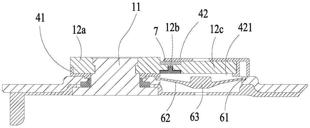
The conductive device 12 includes a post connection portion 12a, a first fuse member 12b, and a contact piece connection portion 12c, and more specifically, the post connection portion 12a is riveted to the riveting portion 11a, the first fuse member 12b and the contact piece connection portion 12c are suspended, and the first fuse member 12b and the contact piece connection portion 12c are disposed on a side of the post connection portion 12a close to the second post 13.
As shown in fig. 3-4, the top cover 14 is electrically connected to the second pole post 13, the top cover 14 is respectively insulated from the first pole post 11 and the conductive piece 12, the top cover 14 is insulated from the first pole post 11 and the conductive piece 12, and the top cover assembly 1 further includes an insulating member 4 and a sealing member 5, the insulating member 4 includes a first portion 41 and a second portion 42, wherein the first portion 41 is clamped and fixed between the top cover plate 14 and the conductive member 12, the rivet portion 11a of the first post 11 passes through the first portion 41 and protrudes outside the top cover plate 14, the second portion 42 surrounds the peripheral edges of the contact piece connecting portion 12c and the first fusing member 12b, the sealing member 5 is fitted over the outside of the lower portion of the rivet portion 11a, and contact with insulating component 4, insulating component 4 has realized the top cover plate 14 with the insulating of first utmost point post 11, and sealing member 5 has realized the sealed of top cover plate 14 with first utmost point post 11.
The rivet portion 11a of the second pole post 13 is further connected with a second pole post conductive member 15, the second pole post 13 can be electrically connected with external components conveniently by the second pole post conductive member 15, and a sealing member having the same structure as the sealing member 5 of the first pole post 11 side is provided at one side of the second pole post 13 to achieve sealing at the second pole post 13. A resistor 16 is connected between the second pole conductive member 15 and the top cover plate 14, the resistor 16 is used for reducing the current in the loop, when the conductor passes through the housing 3 to cause a short circuit in the secondary battery, the resistor 16 can reduce the short circuit current and reduce the occurrence probability of accidents such as fire, and the resistor 16 is designed based on the safety consideration of the secondary battery.
With continued reference to fig. 2 to 4, the secondary battery further includes a contact piece 6, the contact piece 6 is attached to the top cover piece 14, the top cover piece 14 is opened with a hole 141, the contact piece 6 is deformed by the internal pressure when the internal pressure of the secondary battery exceeds the reference pressure, the deformed contact piece 6 can be contacted with the contact piece connecting portion 12c through the hole 141, at this time, the first pole post 11 is electrically connected with the second pole post 13, and the short-circuited state of the secondary battery can be maintained.
Second portion 42 has a through hole 421 formed at a position facing contact piece 6, so that contact piece 6 after deformation contacts contact piece connection portion 12c via through hole 421.
The contact piece 6 includes an edge portion 61, a deformed portion 62, and a central portion 63, the deformed portion 62 connects the edge portion 61 and the central portion 63, the edge portion 61 is attached to the top cover sheet 14, the contact piece 6 after the action is in contact with the contact piece connecting portion 12c via the central portion 63, and the deformed portion 62 is bent to protrude in a direction away from the top cover sheet 14.
The contact piece 6 may be a member having different thicknesses in its respective portions, and the portions having different thicknesses may be protruding portions at portions where the contact piece 6 is in contact with the contact-piece connecting portions 12c, or the contact piece 6 may have a thickness gradually changing from its peripheral region toward its central region and thickest in the central region so as to be in contact with the contact-piece connecting portions 12c when the contact piece 6 is operated.
The first fuse member 12b is capable of fusing at a preset temperature, and thus, has a lower melting point than the pole connection portion 12a and the contact piece connection portion 12c, in order to ensure the reliability of the connection between the first fuse member 12b and both the post connection portion 12a and the contact piece connection portion 12c, so as to function in a hot box test, the conductive member 12 further includes a connection layer (not shown in the drawing), which may be provided on at least one of the post connection portion 12a and the contact piece connection portion 12c, and accordingly, the first fuse member 12b may be connected with the post connection portion 12a via the connection layer, or connected to the contact-piece connecting portion 12c via the connecting layer, or the connecting layer is provided on each of the post connecting portion 12a and the contact-piece connecting portion 12c, and the first fusing member 12b is connected to both of them via the connecting layer.
In the above description, the connection layer may function to increase the connection strength of the first fuse member 12b with the post connection portion 12a and the contact piece connection portion 12 c. On the one hand, in the hot box test, the current can be reliably transmitted between the pole connecting portion 12a and the first fusing member 12b and the contact piece connecting portion 12c, and when the current is heated and reaches the temperature at which the first fusing member 12b fuses, the first fusing member 12b fuses reliably; on the other hand, under normal temperature conditions, when the secondary battery is in an overcharged state, the contact piece deforms under the action of internal pressure and is electrically connected with the contact piece connecting portion, and the arrangement of the connecting layer can reduce the contact resistance of the first fusing member 12b with the pole connecting portion 12a and the contact piece connecting portion 12c, so that the first fusing member 12b is prevented from being fused due to heat generated by overlarge resistance, and the safety of the secondary battery is improved.
According to an embodiment, at least one of the post connection portion 12a and the contact connection portion 12c is made of a first metal material, the first fuse member 12b is made of a second metal material, and the connection layer is made of a third metal material. For different metal materials, the bonding capability is different when the metal materials are cold bonded or hot bonded, and the connecting layer is arranged by utilizing the inherent property of the metal materials, so that the first fusing member 12b has good bonding firmness with the pole connecting part 12a and the contact piece connecting part 12c respectively, and the phenomenon that the connection between the first fusing member 12b and the conductive piece 12 is unreliable is improved.
Optionally, the third metal material may be nickel, nickel alloy, tin alloy, bismuth alloy or the like, the first metal material may be aluminum or aluminum alloy, and the second metal material may be metal at least containing one or more elements of bismuth, tin, lead, zinc or indium. The metal material has good welding manufacturability, and the metal material has higher joint degree and better joint firmness during welding.
Of course, the first metal material, the second metal material and the third metal material are not limited to the above description, and in other embodiments, the three materials may have other different choices.
It should be noted that the connection layer may be provided as a solid component, or may be a plating layer provided on the solid component, which is not limited in the present application. In one embodiment, the connecting layers may be plated, in which case, the number of the connecting layers may be two, one is plated on the pole connecting portion 12a, the other is plated on the first fuse member 12b, and the two connecting layers are joined by welding. The connection layer arranged by plating can reduce the occupation of space, is beneficial to the compactness of the structure of the top cover component 1, and meanwhile, the plating mode can reduce the connection of other modes, thereby reducing the risk of connection failure.
In this application, the top cap assembly 1 further includes a thermal expansion portion 7, the thermal expansion portion 7 is made of an insulating material that expands when heated, as shown in fig. 4, the first fuse member 12b and the thermal expansion portion 7 are arranged along the thickness direction of the conductive member 12, the thermal expansion portion 7 is located above the first fuse member 12b, and the thermal expansion portion 7 is attached to the post connection portion 12a and the contact piece connection portion 12c, respectively. When the heat is applied, the thermal expansion portion 7 expands and deforms, and the contact piece connecting portion 12c is displaced to the side away from the post connecting portion 12a by the expansion force of the thermal expansion portion 7, and at this time, a gap is generated between the post connecting portion 12a and the contact piece connecting portion 12c, and the gap can provide a flow path for the melted first fusing member 12b, so that the first fusing member 12b flows out along the flow path, and thus, the electrical connection loop between the post connecting portion 12a and the contact piece connecting portion 12c is reliably broken.
The thermal expansion part 7 may be made of a plastic material, and may be further provided as an integrated structure with the insulating member 4. Of course, the thermal expansion part 7 may be made of a plastic material separately.
The present application also provides a secondary battery comprising the secondary battery cap assembly 1, the electrode assembly 2 and the case 3 in any of the above embodiments, wherein the secondary battery cap assembly 1 is connected to the opening of the case 3 and forms an encapsulation space, and the electrode assembly 2 is encapsulated in the encapsulation space.
The electrode assembly 2 includes a first pole piece, a second pole piece, and a separator disposed between the first pole piece and the second pole piece, the flange portion 11b of the first pole post 11 is electrically connected to the first pole piece, and the flange portion 11b of the second pole post 13 is electrically connected to the second pole piece.
The electrode assembly 2 is formed by spirally winding a first pole piece, a second pole piece having a polarity opposite to that of the first pole piece, and a separator together. The separator is an insulator between the first and second pole pieces. Alternatively, the electrode assembly 2 may be formed by stacking a plurality of first pole pieces, a plurality of separators, and a plurality of second pole pieces, which are formed in a plate shape or a sheet shape.
The first pole piece may be a negative pole piece, correspondingly, the second pole piece is a positive pole piece; likewise, the first pole piece may also be a positive pole piece, and correspondingly, the second pole piece is a negative pole piece.
The first and second pole pieces each have a thin plate serving as a current collector, the thin plate of the first pole piece having a first coating region coated with an active material and a first tab not coated with the active material; the sheet of the second pole piece has a second coated area coated with an active material and a second tab that is not coated with an active material.
The case 3 is formed to have a substantially cubic shape to form a cavity for accommodating the electrode assembly 2 therein, and the case 3 has an opening at one side.
In order to avoid the phenomena of fire and the like caused by the overheating of the secondary battery in an external short circuit state, the secondary battery further comprises a second fusing member 101, the second fusing member 101 is connected between the first pole post 11 and the first pole piece, and the second fusing member 101 can realize rapid fusing under a large current through a material with a low melting point or a small overcurrent area, so that the current loop is effectively protected.
Similarly, the secondary battery further includes a third fuse member 102, the third fuse member 102 is connected between the second pole 13 and the second pole piece, and the third fuse member 102 has the same function as the second fuse member 101, and thus, the description thereof is omitted.
In addition, a first insulator 104 and a second insulator 105 are disposed between the top cap plate 14 and the electrode assembly 2, the first insulator 104 is used to insulate the top cap plate 14 from the first tab, and the second insulator 105 is used to insulate the top cap plate 14 from the second tab.
The first insulating member 104 has an air hole 104a, and the gas decomposed in the electrode assembly applies pressure to the contact piece 6 through the air hole 104a to deform the contact piece 6.
The secondary battery further includes an explosion-proof valve 106 and an explosion-proof valve protection sheet 107, a pour hole 108, and a pour hole seal and the like. Here, the explosion-proof valve 106 is designed to open when the internal pressure of the secondary battery reaches a predetermined pressure, which may be higher than a threshold pressure at which the contact piece 6 is deformed.
The above description is only a preferred embodiment of the present application and is not intended to limit the present application, and various modifications and changes may be made by those skilled in the art. Any modification, equivalent replacement, improvement and the like made within the spirit and principle of the present application shall be included in the protection scope of the present application.

Claims (9)

1.一种二次电池顶盖组件,包括:第一极柱、导电件、第二极柱以及顶盖片,其特征在于,1. A secondary battery top cover assembly, comprising: a first pole, a conductive member, a second pole and a top cover, characterized in that, 所述顶盖片与所述第一极柱绝缘设置,所述顶盖片与所述第二极柱电连接,所述二次电池还包括接触片,所述接触片附接于所述顶盖片,所述导电件与所述顶盖片绝缘设置,The top cover sheet is insulated from the first pole, the top cover sheet is electrically connected to the second pole, and the secondary battery further includes a contact piece attached to the top a cover sheet, the conductive member is insulated from the top cover sheet, 所述导电件包括极柱连接部、第一熔断构件以及接触片连接部,所述第一熔断构件具有比所述极柱连接部和所述接触片连接部低的熔点,The conductive member includes a pole connecting portion, a first fuse member and a contact piece connecting portion, and the first fuse member has a lower melting point than the pole connecting portion and the contact piece connecting portion, 当二次电池的内部压力超过基准压力时,所述接触片在所述内部压力的作用下变形并与所述接触片连接部电连接,以形成通过所述第一极柱与所述第二极柱的电连接路径,When the internal pressure of the secondary battery exceeds a reference pressure, the contact piece is deformed under the action of the internal pressure and is electrically connected with the contact piece connecting portion to form a connection between the first pole and the second pole through the first pole. the electrical connection path of the pole, 所述导电件还包括连接层,所述第一熔断构件经由所述连接层与所述极柱连接部连接,和/或,所述第一熔断构件经由所述连接层与所述接触片连接部连接;The conductive member further includes a connection layer, the first fuse member is connected to the pole connecting portion via the connection layer, and/or the first fuse member is connected to the contact piece via the connection layer connection; 所述二次电池顶盖组件还包括热膨胀部,所述热膨胀部由绝缘且受热时发生膨胀的材质制成,The secondary battery top cover assembly further includes a thermal expansion part, and the thermal expansion part is made of a material that is insulating and expands when heated, 所述第一熔断构件与所述热膨胀部沿所述导电件的厚度方向排布,所述热膨胀部位于所述第一熔断构件的上方,且所述热膨胀部分别与所述极柱连接部以及所述接触片连接部贴合。The first fuse member and the thermal expansion portion are arranged along the thickness direction of the conductive member, the thermal expansion portion is located above the first fuse member, and the thermal expansion portion is connected to the pole connecting portion and the pole connecting portion, respectively. The contact piece connecting parts are attached. 2.根据权利要求1所述的二次电池顶盖组件,其特征在于,所述极柱连接部和/或所述接触片连接部由第一金属材质制成,所述第一熔断构件由第二金属材质制成,所述连接层由第三金属材质制成,2 . The secondary battery top cover assembly according to claim 1 , wherein the pole connecting portion and/or the contact piece connecting portion is made of a first metal material, and the first fuse member is made of 2 . The second metal material is made of, and the connection layer is made of the third metal material, 所述第三金属材质与所述第一金属材质形成的接合力以及所述第三金属材质与所述第二金属材质形成的接合力均大于所述第一金属材质与所述第二金属材质形成的接合力。The bonding force formed by the third metal material and the first metal material and the bonding force formed by the third metal material and the second metal material are both greater than the first metal material and the second metal material formed bonding force. 3.根据权利要求2所述的二次电池顶盖组件,其特征在于,所述第三金属材质为镍、镍合金、锡、锡合金、铋或铋合金,所述第一金属材质为铝或铝合金,所述第二金属材质为至少包含铋、锡、铅、锌或铟中的一种或几种元素的金属。3. The secondary battery top cover assembly according to claim 2, wherein the third metal material is nickel, nickel alloy, tin, tin alloy, bismuth or bismuth alloy, and the first metal material is aluminum Or an aluminum alloy, the second metal material is a metal containing at least one or several elements of bismuth, tin, lead, zinc or indium. 4.根据权利要求1所述的二次电池顶盖组件,其特征在于,所述连接层的数量为两个,一者连接于所述极柱连接部,另一者连接于所述第一熔断构件,两个所述连接层焊接。4 . The top cover assembly of claim 1 , wherein the number of the connecting layers is two, one is connected to the pole connecting portion, and the other is connected to the first In the fuse member, the two connection layers are welded. 5.根据权利要求1-4任一项所述的二次电池顶盖组件,其特征在于,还包括绝缘构件,所述导电件通过所述绝缘构件与所述顶盖片绝缘设置,5. The secondary battery top cover assembly according to any one of claims 1-4, further comprising an insulating member, and the conductive member is insulated from the top cover sheet through the insulating member, 所述绝缘构件设置有第一通孔,变形后的所述接触片穿过所述第一通孔与所述接触片连接部接触。The insulating member is provided with a first through hole, and the deformed contact piece passes through the first through hole and contacts with the contact piece connecting portion. 6.根据权利要求5所述的二次电池顶盖组件,其特征在于,所述绝缘构件包括相连接的第一部分和第二部分,所述第一部分固定于所述极柱连接部与所述顶盖片之间,所述第二部分包围所述接触片连接部的周围,6 . The secondary battery top cover assembly according to claim 5 , wherein the insulating member comprises a first part and a second part that are connected to each other, and the first part is fixed between the pole connecting part and the Between the top cover sheets, the second part surrounds the periphery of the connection part of the contact sheet, 所述第一通孔开设于所述第二部分。The first through hole is opened in the second part. 7.根据权利要求1-4任一项所述的二次电池顶盖组件,其特征在于,还包括绝缘构件,所述导电件通过所述绝缘构件与所述顶盖片绝缘设置,所述绝缘构件和所述热膨胀部为一体式结构。7. The secondary battery top cover assembly according to any one of claims 1-4, further comprising an insulating member, the conductive member is insulated from the top cover sheet through the insulating member, and the The insulating member and the thermal expansion part have a one-piece structure. 8.一种二次电池,包括二次电池顶盖组件、壳体以及电极组件,所述二次电池顶盖组件连接于所述壳体的开口处并形成封装空间,8. A secondary battery, comprising a secondary battery top cover assembly, a casing and an electrode assembly, the secondary battery top cover assembly being connected to an opening of the casing and forming an encapsulation space, 所述电极组件包括第一极片、第二极片以及设置在所述第一极片与所述第二极片之间的隔板,所述第一极柱与所述第一极片电连接,所述第二极柱与所述第二极片电连接;The electrode assembly includes a first pole piece, a second pole piece, and a separator disposed between the first pole piece and the second pole piece, and the first pole piece is electrically connected to the first pole piece. connected, the second pole is electrically connected to the second pole piece; 所述电极组件封装在所述封装空间内,其特征在于,The electrode assembly is encapsulated in the encapsulation space, and is characterized in that: 所述二次电池顶盖组件为权利要求1-7任一项所述的二次电池顶盖组件。The secondary battery top cover assembly is the secondary battery top cover assembly of any one of claims 1-7. 9.根据权利要求8所述的二次电池,其特征在于,还包括第二熔断构件,所述第一极柱通过所述第二熔断构件与所述第一极片电连接,9 . The secondary battery according to claim 8 , further comprising a second fuse member, the first pole post is electrically connected to the first pole piece through the second fuse member, 10 . 和/或,and / or, 所述二次电池还包括第三熔断构件,所述第二极柱通过所述第三熔断构件与所述第二极片电连接。The secondary battery further includes a third fuse member, and the second pole post is electrically connected to the second pole piece through the third fuse member.
CN201710599686.4A 2017-07-20 2017-07-20 Secondary battery top cover assembly and secondary battery Active CN109285974B (en)

Priority Applications (2)

Application Number Priority Date Filing Date Title
CN201710599686.4A CN109285974B (en) 2017-07-20 2017-07-20 Secondary battery top cover assembly and secondary battery
US15/950,617 US10770696B2 (en) 2017-07-20 2018-04-11 Top cover assembly of secondary battery and secondary battery

Applications Claiming Priority (1)

Application Number Priority Date Filing Date Title
CN201710599686.4A CN109285974B (en) 2017-07-20 2017-07-20 Secondary battery top cover assembly and secondary battery

Publications (2)

Publication Number Publication Date
CN109285974A CN109285974A (en) 2019-01-29
CN109285974B true CN109285974B (en) 2021-08-03

Family

ID=65023207

Family Applications (1)

Application Number Title Priority Date Filing Date
CN201710599686.4A Active CN109285974B (en) 2017-07-20 2017-07-20 Secondary battery top cover assembly and secondary battery

Country Status (2)

Country Link
US (1) US10770696B2 (en)
CN (1) CN109285974B (en)

Families Citing this family (16)

* Cited by examiner, † Cited by third party
Publication number Priority date Publication date Assignee Title
KR102632924B1 (en) * 2018-09-19 2024-02-02 삼성에스디아이 주식회사 Secondary Battery
JP7442269B2 (en) * 2019-03-29 2024-03-04 三洋電機株式会社 secondary battery
CN110176557B (en) * 2019-04-09 2024-04-05 宁德时代新能源科技股份有限公司 Secondary battery and top cover assembly thereof
CN113224427A (en) * 2020-01-21 2021-08-06 常州微宙电子科技有限公司 PCB type battery cover plate, preparation method thereof and battery with PCB type battery cover plate
JP7414701B2 (en) * 2020-12-03 2024-01-16 プライムプラネットエナジー&ソリューションズ株式会社 Secondary batteries and assembled batteries
KR102908429B1 (en) * 2021-02-16 2026-01-06 에스케이온 주식회사 battery module
CN215816073U (en) * 2021-08-17 2022-02-11 厦门海辰新能源科技有限公司 Top cover assembly of battery core, battery core and power battery
CN216720246U (en) * 2022-01-28 2022-06-10 宁德时代新能源科技股份有限公司 Insurance structure, battery and electrical device
CN217468606U (en) * 2022-07-01 2022-09-20 宁德时代新能源科技股份有限公司 End cap components, battery cells, batteries and electrical equipment
CN115939691A (en) * 2023-02-09 2023-04-07 深圳海润新能源科技有限公司 End cover assembly, energy storage device and electric equipment
CN116470243A (en) * 2023-05-04 2023-07-21 珠海冠宇电池股份有限公司 A safety structure and electrochemical device
CN116526086B (en) * 2023-06-29 2023-09-19 楚能新能源股份有限公司 Posts and batteries
CN120784583A (en) * 2024-04-08 2025-10-14 宁德时代新能源科技股份有限公司 Battery cell, battery, energy storage device and electricity utilization device
CN222927658U (en) * 2024-05-27 2025-05-30 宁德时代新能源科技股份有限公司 Battery cell, battery, energy storage device and electricity utilization device
CN121054977A (en) * 2024-05-31 2025-12-02 宁德时代新能源科技股份有限公司 Battery cells, batteries, energy storage devices and electrical appliances
CN121238190A (en) * 2024-06-27 2025-12-30 宁德时代新能源科技股份有限公司 Battery monomer, battery, energy storage equipment and electric equipment

Citations (9)

* Cited by examiner, † Cited by third party
Publication number Priority date Publication date Assignee Title
CN1621113A (en) * 2003-11-25 2005-06-01 楠盛股份有限公司 Bonding structure of golf club head
CN101112740A (en) * 2006-07-25 2008-01-30 日产自动车株式会社 Joining method, joining structure and joining device of dissimilar metals
CN101643899A (en) * 2009-09-05 2010-02-10 中国船舶重工集团公司第七二五研究所 Preparation method of different-metal material welding middle layer
US8455977B2 (en) * 2009-06-22 2013-06-04 Broadcom Corporation Programmable fuse
CN103247817A (en) * 2012-02-01 2013-08-14 三星Sdi株式会社 Rechargeable battery
CN103580001A (en) * 2012-07-24 2014-02-12 三星Sdi株式会社 Current breaking device and battery pack having the same
CN104425446A (en) * 2013-08-20 2015-03-18 中芯国际集成电路制造(上海)有限公司 Fuse structure and using method thereof
CN106159183A (en) * 2014-11-20 2016-11-23 现代自动车株式会社 Expansion type current interrupt device
JP2017050091A (en) * 2015-08-31 2017-03-09 矢崎総業株式会社 Battery terminal block

Family Cites Families (11)

* Cited by examiner, † Cited by third party
Publication number Priority date Publication date Assignee Title
US9368772B1 (en) * 2009-06-15 2016-06-14 Sakti3, Inc. Packaging and termination structure for a solid state battery
US9478774B2 (en) * 2010-12-02 2016-10-25 Samsung Sdi Co., Ltd. Rechargeable battery
KR101666257B1 (en) * 2013-01-16 2016-10-13 삼성에스디아이 주식회사 Rechargeable battery for supressing arc occurance
CN203644815U (en) * 2013-12-18 2014-06-11 江阴长电先进封装有限公司 LED packaging structure
KR102273768B1 (en) * 2014-04-01 2021-07-06 삼성에스디아이 주식회사 Secondary battery
KR102246729B1 (en) * 2014-04-17 2021-04-29 삼성에스디아이 주식회사 Rechargeable battery having current dispersion member
KR102303568B1 (en) * 2014-08-08 2021-09-17 삼성에스디아이 주식회사 Rechargeable battery having fuse
JP6707367B2 (en) * 2016-02-29 2020-06-10 三洋電機株式会社 Secondary battery and battery pack
CN109417134B (en) * 2016-06-29 2021-12-03 三洋电机株式会社 Secondary battery
KR102325844B1 (en) * 2016-10-21 2021-11-11 삼성에스디아이 주식회사 Rechargeable battery
CN113488747B (en) * 2017-02-14 2024-01-09 宁德时代新能源科技股份有限公司 Power battery

Patent Citations (9)

* Cited by examiner, † Cited by third party
Publication number Priority date Publication date Assignee Title
CN1621113A (en) * 2003-11-25 2005-06-01 楠盛股份有限公司 Bonding structure of golf club head
CN101112740A (en) * 2006-07-25 2008-01-30 日产自动车株式会社 Joining method, joining structure and joining device of dissimilar metals
US8455977B2 (en) * 2009-06-22 2013-06-04 Broadcom Corporation Programmable fuse
CN101643899A (en) * 2009-09-05 2010-02-10 中国船舶重工集团公司第七二五研究所 Preparation method of different-metal material welding middle layer
CN103247817A (en) * 2012-02-01 2013-08-14 三星Sdi株式会社 Rechargeable battery
CN103580001A (en) * 2012-07-24 2014-02-12 三星Sdi株式会社 Current breaking device and battery pack having the same
CN104425446A (en) * 2013-08-20 2015-03-18 中芯国际集成电路制造(上海)有限公司 Fuse structure and using method thereof
CN106159183A (en) * 2014-11-20 2016-11-23 现代自动车株式会社 Expansion type current interrupt device
JP2017050091A (en) * 2015-08-31 2017-03-09 矢崎総業株式会社 Battery terminal block

Also Published As

Publication number Publication date
US20190027717A1 (en) 2019-01-24
CN109285974A (en) 2019-01-29
US10770696B2 (en) 2020-09-08

Similar Documents

Publication Publication Date Title
CN109285974B (en) Secondary battery top cover assembly and secondary battery
CN100483830C (en) Rechargeable battery
KR100922474B1 (en) Secondary battery
CN102035186B (en) Current interrupting device and secondary battery including current interrupting device
US9059459B2 (en) Secondary battery
US10411225B2 (en) Power battery and cap structure of the power battery
CN109659483B (en) Secondary battery top cover assembly and secondary battery
CN207038570U (en) Secondary battery top cover assembly and secondary battery
CN106654137B (en) Battery cell
CN100474663C (en) Rechargeable battery
CN109585771B (en) Secondary battery top cover assembly and secondary battery
JP2016521449A (en) Connexing component for secondary battery and secondary battery including the same
US20070020509A1 (en) Rechargeable battery with ptc device
KR20050110504A (en) Secondary battery
KR100561311B1 (en) Secondary Battery
KR100490547B1 (en) Lithium secondary battery having a protective mean
KR20090030711A (en) Bare cell and secondary battery including same
KR100515355B1 (en) Secondary battery
JP2009527885A (en) Safety device for high power battery
KR20080038662A (en) Secondary battery
KR20080036737A (en) Secondary battery

Legal Events

Date Code Title Description
PB01 Publication
PB01 Publication
SE01 Entry into force of request for substantive examination
GR01 Patent grant
GR01 Patent grant