CN109270668B - Telecentric projection lens and image output equipment - Google Patents
Telecentric projection lens and image output equipment Download PDFInfo
- Publication number
- CN109270668B CN109270668B CN201811485621.8A CN201811485621A CN109270668B CN 109270668 B CN109270668 B CN 109270668B CN 201811485621 A CN201811485621 A CN 201811485621A CN 109270668 B CN109270668 B CN 109270668B
- Authority
- CN
- China
- Prior art keywords
- lens
- lens group
- image
- group
- biconvex
- Prior art date
- Legal status (The legal status is an assumption and is not a legal conclusion. Google has not performed a legal analysis and makes no representation as to the accuracy of the status listed.)
- Active
Links
- 230000003287 optical effect Effects 0.000 claims abstract description 30
- 238000003384 imaging method Methods 0.000 claims abstract description 20
- 230000005499 meniscus Effects 0.000 claims description 34
- 230000001681 protective effect Effects 0.000 claims description 4
- 238000004519 manufacturing process Methods 0.000 abstract description 7
- 230000004075 alteration Effects 0.000 description 14
- 238000010586 diagram Methods 0.000 description 12
- 239000011521 glass Substances 0.000 description 11
- 239000000463 material Substances 0.000 description 7
- 239000010453 quartz Substances 0.000 description 5
- VYPSYNLAJGMNEJ-UHFFFAOYSA-N silicon dioxide Inorganic materials O=[Si]=O VYPSYNLAJGMNEJ-UHFFFAOYSA-N 0.000 description 5
- 230000000694 effects Effects 0.000 description 3
- 230000006870 function Effects 0.000 description 3
- 238000005286 illumination Methods 0.000 description 3
- 230000004304 visual acuity Effects 0.000 description 3
- 230000009286 beneficial effect Effects 0.000 description 2
- 230000004048 modification Effects 0.000 description 2
- 238000012986 modification Methods 0.000 description 2
- 210000001747 pupil Anatomy 0.000 description 2
- 206010010071 Coma Diseases 0.000 description 1
- 230000008859 change Effects 0.000 description 1
- 239000007795 chemical reaction product Substances 0.000 description 1
- 238000004939 coking Methods 0.000 description 1
- 230000006872 improvement Effects 0.000 description 1
- 230000001678 irradiating effect Effects 0.000 description 1
- 238000000034 method Methods 0.000 description 1
- 230000008569 process Effects 0.000 description 1
- 239000000047 product Substances 0.000 description 1
- 230000009467 reduction Effects 0.000 description 1
- 238000002834 transmittance Methods 0.000 description 1
Images


Classifications
-
- G—PHYSICS
- G02—OPTICS
- G02B—OPTICAL ELEMENTS, SYSTEMS OR APPARATUS
- G02B13/00—Optical objectives specially designed for the purposes specified below
- G02B13/001—Miniaturised objectives for electronic devices, e.g. portable telephones, webcams, PDAs, small digital cameras
- G02B13/0015—Miniaturised objectives for electronic devices, e.g. portable telephones, webcams, PDAs, small digital cameras characterised by the lens design
- G02B13/002—Miniaturised objectives for electronic devices, e.g. portable telephones, webcams, PDAs, small digital cameras characterised by the lens design having at least one aspherical surface
- G02B13/0045—Miniaturised objectives for electronic devices, e.g. portable telephones, webcams, PDAs, small digital cameras characterised by the lens design having at least one aspherical surface having five or more lenses
-
- G—PHYSICS
- G02—OPTICS
- G02B—OPTICAL ELEMENTS, SYSTEMS OR APPARATUS
- G02B13/00—Optical objectives specially designed for the purposes specified below
- G02B13/001—Miniaturised objectives for electronic devices, e.g. portable telephones, webcams, PDAs, small digital cameras
- G02B13/0055—Miniaturised objectives for electronic devices, e.g. portable telephones, webcams, PDAs, small digital cameras employing a special optical element
- G02B13/006—Miniaturised objectives for electronic devices, e.g. portable telephones, webcams, PDAs, small digital cameras employing a special optical element at least one element being a compound optical element, e.g. cemented elements
-
- G—PHYSICS
- G02—OPTICS
- G02B—OPTICAL ELEMENTS, SYSTEMS OR APPARATUS
- G02B13/00—Optical objectives specially designed for the purposes specified below
- G02B13/22—Telecentric objectives or lens systems
-
- G—PHYSICS
- G02—OPTICS
- G02B—OPTICAL ELEMENTS, SYSTEMS OR APPARATUS
- G02B13/00—Optical objectives specially designed for the purposes specified below
- G02B13/24—Optical objectives specially designed for the purposes specified below for reproducing or copying at short object distances
-
- G—PHYSICS
- G03—PHOTOGRAPHY; CINEMATOGRAPHY; ANALOGOUS TECHNIQUES USING WAVES OTHER THAN OPTICAL WAVES; ELECTROGRAPHY; HOLOGRAPHY
- G03B—APPARATUS OR ARRANGEMENTS FOR TAKING PHOTOGRAPHS OR FOR PROJECTING OR VIEWING THEM; APPARATUS OR ARRANGEMENTS EMPLOYING ANALOGOUS TECHNIQUES USING WAVES OTHER THAN OPTICAL WAVES; ACCESSORIES THEREFOR
- G03B21/00—Projectors or projection-type viewers; Accessories therefor
- G03B21/14—Details
- G03B21/142—Adjusting of projection optics
Landscapes
- Physics & Mathematics (AREA)
- Optics & Photonics (AREA)
- General Physics & Mathematics (AREA)
- Lenses (AREA)
Abstract
The invention provides a telecentric projection lens and image output equipment, and relates to the field of projection lenses. This telecentric projection lens includes: the lens comprises a first lens group, a second lens group, a third lens group and a prism, wherein the first lens group is close to an object plane, the third lens group is close to an image plane, the second lens group is arranged between the first lens group and the third lens group, and the prism is arranged between the third lens group and the image plane. The optical axes of the first lens group, the second lens group and the third lens group are coincident. The first lens group has negative diopter, the second lens group has positive diopter, and the third lens group has positive diopter, wherein the first lens group, the second lens group and the third lens group form a telecentric structure. The projection lens has the advantages of short focal length, small lens size and compact structure, and meanwhile, the imaging quality is improved, and the cost is reduced during mass production.
Description
Technical Field
The invention relates to the technical field of projection lenses, in particular to a telecentric projection lens and image output equipment.
Background
The projector is more and more widely used in teaching, life and work, the projection quality of the projector is a key factor for judging the quality of the projector, the projection lens is the last part of the light path of the projector, the quality of the projection lens determines the projection quality, the quality of the projection lens is improved, and the projection quality of the projector can be directly improved.
In the process that projection lens developed towards the little projection direction, the requirement to projection lens is higher and higher, and the camera lens structure among the prior art is loose, and the camera lens size is big, and the resolving power is not good enough, and luminance is not enough, and the volume production is with high costs, can't satisfy present demand to miniaturized, the short coking of projecting apparatus.
Therefore, a projection lens with compact structure and good projection effect, which is suitable for mass production, is needed.
Disclosure of Invention
The present invention is directed to provide a telecentric projection lens and an image output apparatus, which solve the problems of large size, poor projection effect, and high cost of mass production of the projection lens.
In order to achieve the above purpose, the embodiment of the present invention adopts the following technical solutions:
in a first aspect, an embodiment of the present invention provides a telecentric projection lens, including:
the lens comprises a first lens group, a second lens group, a third lens group and a prism, wherein the first lens group is close to an object plane, the third lens group is close to an image plane, the second lens group is arranged between the first lens group and the third lens group, and the prism is arranged between the third lens group and the image plane. The optical axes of the first lens group, the second lens group, the third lens group and the prism are coincident. The first lens group has negative diopter, the second lens group has positive diopter, and the third lens group has positive diopter, wherein the first lens group, the second lens group and the third lens group form a telecentric structure.
Further, the first lens group includes: the lens comprises a first negative meniscus lens and a second negative meniscus lens, wherein the first negative meniscus lens is arranged close to an object plane, and the second negative meniscus lens is arranged close to an image plane. The first negative meniscus lens and the second negative meniscus lens have a negative refractive power. The object side surface and the image side surface of the first negative meniscus lens are both convex and concave and are aspheric. The object side surface and the image side surface of the second negative meniscus lens are convex and concave, and are spherical.
Further, the second lens group includes a first biconvex lens. The first biconvex lens has a positive refractive power. The object side surface and the image side surface of the first biconvex lens are both convex surfaces and are both spherical surfaces.
Further, the third lens group includes: the optical lens comprises a first cemented lens and a second biconvex lens, wherein the first cemented lens is arranged close to an object plane, and the second biconvex lens is arranged close to an image plane. The first cemented lens has a negative refractive power and includes a first biconcave lens and a third biconvex lens, and an image-side surface of the first biconcave lens is attached to an object-side surface of the third biconvex lens. The object side surface of the first biconcave lens, the image side surface of the third biconvex lens, and the joint surfaces of the first biconcave lens and the third biconvex lens are all spherical surfaces. The second biconvex lens has a positive refractive power, and both the object side surface and the image side surface of the second biconvex lens are convex and aspheric.
Furthermore, the lens further comprises a diaphragm which is arranged between the second lens group and the third lens group and is used for controlling the throughput of the light rays.
And the protection lens is arranged between the prism and the image plane and is used for protecting an imaging component placed on the image plane.
Optionally, 4.5< TTL/f <7.5, where TTL is a total lens length and represents a distance from the object plane of the first lens group to the image plane, and f is an effective focal length of the lens.
Optionally, BFL/f >2.2, where BFL is a back focal length of the lens, which represents a distance from the image side surface of the third lens group to the image plane, and f is an effective focal length of the lens.
Optionally, when the distance between the object plane and the telecentric projection lens is changed, the distances between the first lens group, the second lens group, the third lens group and the image plane are adjusted to obtain a clear image.
In a second aspect, an embodiment of the present invention further provides an image output apparatus, including the telecentric projection lens in the first aspect.
The invention has the beneficial effects that: through first lens group, second lens group, third lens group constitutes the telecentric structure of side of giving an image, light is through first lens group, second lens group, the refraction of third lens group back, the telecentric light path has been realized, therefore the focus is short, the camera lens size is little, compact structure, it is little to have the throw simultaneously, image plane illuminance is even, the contrast is good, the effect that energy utilization is high, the imaging quality has been promoted, and the assembly tolerance is loose, easily production and assembly, cost reduction during mass production.
Drawings
In order to more clearly illustrate the technical solutions of the embodiments of the present invention, the drawings needed to be used in the embodiments will be briefly described below, it should be understood that the following drawings only illustrate some embodiments of the present invention and therefore should not be considered as limiting the scope, and for those skilled in the art, other related drawings can be obtained according to the drawings without inventive efforts.
Fig. 1 is a schematic structural diagram of a telecentric projection lens according to an embodiment of the present invention;
FIG. 2 is a schematic view of a telecentric projection lens according to an embodiment of the present invention;
FIG. 3 is a field curvature and distortion aberration diagram of a telecentric projection lens according to a first embodiment of the present invention;
fig. 4 is a Modulation Transfer Function (MTF) graph of a telecentric projection lens according to a first embodiment of the present invention;
FIG. 5 is a vertical axis aberration diagram of a telecentric projection lens according to a first embodiment of the present invention;
FIG. 6 is a field curvature and distortion aberration diagram of a telecentric projection lens provided in a second embodiment of the present invention;
fig. 7 is a graph of MTF of a telecentric projection lens provided in a second embodiment of the present invention;
FIG. 8 is a vertical axis aberration diagram of a telecentric projection lens provided in a second embodiment of the present invention;
fig. 9 is a schematic structural diagram of an image output apparatus according to an embodiment of the present invention.
Icon: 1-a first lens group; 11-a first negative meniscus lens; 12-a second negative meniscus lens; 2-a second lens group; 21-a first biconvex lens; 3-a third lens group; 31-a first biconcave lens; 32-a third lenticular lens; 33-a second biconvex lens; 4-a diaphragm; 5-a prism; 6-protective lens; 7-Digital Micromirror Device (DMD).
Detailed Description
In order to make the objects, technical solutions and advantages of the embodiments of the present invention clearer, the technical solutions in the embodiments of the present invention will be clearly and completely described below with reference to the drawings in the embodiments of the present invention, and it is obvious that the described embodiments are some, but not all, embodiments of the present invention. The components of embodiments of the present invention generally described and illustrated in the figures herein may be arranged and designed in a wide variety of different configurations.
Thus, the following detailed description of the embodiments of the present invention, presented in the figures, is not intended to limit the scope of the invention, as claimed, but is merely representative of selected embodiments of the invention. All other embodiments, which can be derived by a person skilled in the art from the embodiments given herein without making any creative effort, shall fall within the protection scope of the present invention. It should be noted that: like reference numbers and letters refer to like items in the following figures, and thus, once an item is defined in one figure, it need not be further defined and explained in subsequent figures.
In the description of the present invention, it should be noted that the terms "first", "second", "third", and the like are used for distinguishing description only and are not to be construed as indicating or implying relative importance, and meanwhile, the image side and the object side are in a conjugate relationship.
Fig. 1 is a schematic structural diagram of a telecentric projection lens according to an embodiment of the present invention.
As shown in fig. 1, the telecentric projection lens includes:
the image sensor comprises a first lens group 1, a second lens group 2, a third lens group 3 and a prism 5, wherein the first lens group 1 is close to an object plane, the third lens group 3 is close to an image plane, the second lens group 2 is arranged between the first lens group 1 and the third lens group 3, and the prism 5 is arranged between the third lens group 3 and the image plane.
The prism 5 is a beam splitter prism for turning the optical path, for example, in the use of the telecentric projection lens, there are an illumination optical path and an imaging optical path, and the illumination optical path and the imaging optical path are connected by the beam splitter prism to form a complete projection optical path.
The optical axes of the first lens group 1, the second lens group 2, the third lens group 3 and the prism 5 coincide with each other. The first lens group 1 has negative diopter, the second lens group 2 has positive diopter, and the third lens group 3 has positive diopter, wherein the first lens group 1, the second lens group 2, and the third lens group 3 constitute a telecentric structure.
The telecentric structure is that the chief ray is approximately parallel to the optical axis after the light passes through the lens, and in this embodiment, the included angle between the chief ray and the optical axis after the light passes through the lens is less than 1 °.
It should be noted that the lens group refers to a lens combination composed of at least one lens, and the at least one lens achieves the optical performance required by the lens group, and the number and the type of the lenses in the lens group are not limited, so as to achieve the optical performance.
According to the telecentric projection lens provided by the embodiment of the invention, the first lens group, the second lens group and the third lens group form the imaging telecentric structure, and light rays are refracted by the first lens group, the second lens group and the third lens group to realize a telecentric light path, so that the telecentric projection lens has the advantages of short focal length, small lens size, compact structure, small projection ratio, uniform image plane illumination, good contrast, high energy utilization rate and high energy utilization rate, improves the imaging quality, has loose assembly tolerance, is easy to produce and assemble, and reduces the cost in mass production.
To better illustrate the structure of the telecentric projection lens shown in fig. 1 and its mirror parameters, a description of one possible implementation is given below.
Specifically, fig. 2 is a schematic view of a mirror surface of a telecentric projection lens according to an embodiment of the present invention.
As shown in fig. 1 and 2, the first lens group 1 includes: the image pickup lens includes a first negative meniscus lens 11 and a second negative meniscus lens 12, wherein the first negative meniscus lens 11 is disposed close to the object plane, and the second negative meniscus lens 12 is disposed close to the image plane S15.
The first negative meniscus lens 11 and the second negative meniscus lens 12 have a negative refractive power. The object-side surface S1 and the image-side surface S2 of the first negative meniscus lens 11 are aspheric. The object-side surface S3 and the image-side surface S4 of the second negative meniscus lens 12 are both convex and concave.
It should be noted that, f is used herein to denote the focal length, and the unit is millimeter; r represents a surface radius of curvature of the optical lens in millimeters; d is the on-axis distance in millimeters from the corresponding optical surface to the subsequent optical surface; nd is a refractive index of the optical lens corresponding to d light (the wavelength of light is 587nm), and Vd is an Abbe number of the optical lens corresponding to d light.
In this embodiment, the first negative meniscus lens 11 is made of plastic, and the focal length satisfies-21.4 < f < -15.1; the refractive index satisfies: 1.50< Nd < 1.65; the Abbe number satisfies: 22< Vd < 60.
The first negative meniscus lens 11 is an aspherical mirror, the imaging quality of the lens can be effectively improved by using the aspherical mirror, and the aspherical surface of the lens can be represented by the following formula:

wherein: z represents a distance in the optical axis direction from a point on the aspherical surface to the vertex of the aspherical surface, r represents a distance from a point on the non-surface to the optical axis, c represents a central curvature of the aspherical surface, k represents a conicity, and a4, a6, a8, a10, a12 represent aspherical high-order term coefficients.
The second negative meniscus lens 12 is made of glass, and the focal length satisfies: -21.7< f < -18.5, the refractive index satisfying: 1.48< Nd <1.6, the abbe number satisfies: 55< Vd < 85.
Optionally, the first negative meniscus lens 11 may be made of glass, quartz, or other materials meeting optical performance, and the second negative meniscus lens 12 may be made of plastic, quartz, or other materials meeting optical performance.
The second lens group 2 includes a first biconvex lens 21.
The first biconvex lens 21 has a positive refractive power. The object-side surface S5 and the image-side surface S6 of the first biconvex lens 21 are both convex and spherical.
Wherein, the material of first biconvex lens 21 is glass, and the focus satisfies: 8.2< f <12.1, the refractive index satisfies: 1.75< Nd <1.92, the abbe number satisfies: 30< Vd < 40.
Optionally, the first biconvex lens 21 may also be made of plastic, quartz, or other materials that satisfy optical properties.
The third lens group 3 includes: a first cemented lens disposed near the object plane and a second biconvex lens 33 disposed near the image plane S15. The first cemented lens has a negative refractive power and includes a first biconcave lens 31 and a third biconvex lens 32, and an image-side surface of the first biconcave lens 31 is attached to an object-side surface of the third biconvex lens 32. The object side surface S7 of the first double-concave lens 31, the image side surface S9 of the third double-convex lens 32, and the attaching surface S8 of the first double-concave lens 31 and the third double-convex lens 32 are all spherical surfaces. The second biconvex lens 33 has positive refractive power, and both the object side surface S10 and the image side surface S11 of the second biconvex lens 33 are convex and aspheric.
Optionally, the first cemented lens of the first double-concave lens 31 and the third double-convex lens 32 is made of glass.
Wherein, first biconcave lens 31 and third biconvex lens 32 constitute two cemented lens, and behind the two cemented lens of constitution, this two cemented lens's focus satisfies: -60< f < -20, the refractive index of the first biconcave lens 31 satisfying: 1.75< Nd <1.95, and the refractive index of the third biconvex lens 32 satisfies: 1.50< Nd < 1.75. The abbe number of the first biconcave lens 31 satisfies: 22< Vd <35, the abbe number of the third lenticular lens 32 satisfies: 45< Vd < 65.
Alternatively, the first biconcave lens 31 and the third biconvex lens 32 may be made of plastic, quartz, or other materials that satisfy optical properties.
The second biconvex lens 33 is made of glass, and the focal length satisfies: 7.5< f <10.2, the refractive index satisfies: 1.65< Nd <1.75, the abbe number satisfies: 45< Vd < 57.
The second biconvex lens 33 is an aspherical mirror made of glass, and the aspherical representation is the same as the above formula, which is not described herein again. The aspherical mirror made of glass materials is used in the lens, so that the imaging quality of the lens can be improved, and the problem of lens thermal defocus can be solved.
Optionally, the second biconvex lens 33 may also be made of plastic, quartz, or other materials that satisfy optical properties.
Furthermore, the telecentric projection lens further comprises a diaphragm 4, and the diaphragm 4 is arranged between the second lens group 2 and the third lens group 3 and is used for controlling the throughput of light rays.
In this embodiment, the diaphragm 4 is disposed between the second lens group 2 and the third lens group 3, so that the overall structure of the lens is relatively symmetrical, coma aberration and distortion can be effectively balanced, and the imaging quality of the lens is improved.
Optionally, as for the diaphragm 4 in the embodiment of the present invention, the position of the diaphragm may also be between the first lens group 1 and the second lens group 2, and the specific position thereof may be defined according to product requirements. The final implementation form can be obtained by a person skilled in the art without creative work after reading the scheme provided by the embodiment of the invention.
Further, the telecentric projection lens further comprises a protective lens 6, wherein the protective lens 6 is arranged between the prism 5 and the image plane S15 and is used for protecting the imaging element placed on the image plane S15.
The imaging element includes DMD7, and DMD7 is integrally formed with protective lens 6.
Optionally, 4.5< TTL/f <7.5, where TTL is a total lens length and represents a distance from the object side surface of the first lens group 1 to the image plane S15, and f is an effective focal length of the lens.
In this embodiment, in order to reduce the size of the lens, it is necessary to limit the total lens length, and the effective focal length of the lens is constant after the lens structure is determined, so that the TTL/f is limited to 4.5-7.5, and the range of the total lens length is limited, which can balance the total lens length and the aberration to make the total lens length in a better range under the condition of ensuring the total lens length and the transmittance.
Optionally, BFL/f >2.2, where BFL is a back lens focal length, representing a distance from the image side surface of the third lens group 3 to the image plane S15, and f is a lens effective focal length.
In the present embodiment, in order to have enough space for placing the prism 5, it is necessary to make some limitation on the back focal length of the lens, and when BFL/f >2.2, there is enough space for placing the prism 5 between the second biconvex lens 33 and the image plane S15.
Optionally, when the distance between the object plane and the telecentric projection lens is changed, the distances between the first lens group 1, the second lens group 2, the third lens group 3 and the image plane S15 are adjusted to obtain a sharp image.
In this embodiment, when the image projected by the lens is irradiated on the display medium, the plane of the display medium and the object plane are not in the same plane, which results in a blurred projected image, in this case, a focusing operation needs to be performed, for example, by adjusting the distances between the first lens group 1, the second lens group 2, the third lens group 3 and the image plane S15, to change the position of the plane of the object plane, so as to obtain a sharp image, wherein the distances between the first lens group 1, the second lens group 2, and the third lens group 3 and the image plane S15 are kept unchanged.
Optionally, the focusing operation may also be implemented by changing distances among the first lens group 1, the second lens group 2, and the third lens group 3, and how to implement the focusing operation is not limited herein.
The telecentric projection lens provided by the invention has multiple possible implementation modes, and the telecentric projection lens is explained by taking a scene one and a scene two as examples. The parameters in scene one and scene two are merely examples of implementations of telecentric projection lenses, and are not limited to necessarily being set as such.
Scene one
Referring to fig. 1 and 2, in scenario one, the parameters of the respective glasses of the first lens group 1, the second lens group 2, and the third lens group 3, the prism 5, the protection glass 6, and the DMD7 are as follows:


the first negative meniscus lens 11 and the second biconvex lens 33 are aspherical lenses, and the coefficients of the respective orders are shown in the following table:
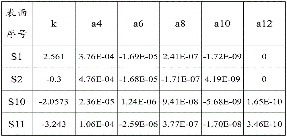
the focal length F of the telecentric projection lens is 6.27mm, the total length TTL is 38.3mm, and the aperture FNo.1.7, where the aperture is the reciprocal of the relative aperture. It should be noted that the relative aperture is the ratio of the diameter of the entrance pupil, which is the diameter of the diaphragm 4 imaged on the optical system in front of it, to the focal length.
Fig. 3 is a field curvature and distortion aberration diagram of a telecentric projection lens according to a first embodiment of the present invention.
As shown in fig. 3, the field curvature of the telecentric projection lens provided by the first scene of the present embodiment is less than 0.05mm, and the maximum distortion is 0.8%.
Fig. 4 is a graph of MTF of a telecentric projection lens according to a first embodiment of the invention.
As shown in FIG. 4, the MTF of the full field of the telecentric projection lens provided in the first embodiment of the scene is > 48% at the spatial frequency of 93 lp/mm.
Fig. 5 is a vertical axis chromatic aberration diagram of a telecentric projection lens according to a first embodiment of the present invention.
As shown in FIG. 5, the vertical axis chromatic aberration of the imaging system of the telecentric projection lens provided in the first scenario of the present embodiment is at most 3.6 μm.
According to the parameters, the telecentric projection lens provided by the first scene has small distortion, excellent MTF performance, small vertical axis chromatic aberration, short focal length, strong resolving power, F1.7 aperture, excellent imaging quality and solves the problem of thermal defocusing to a certain degree.
Scene two
Referring to fig. 1 and 2, in a second scenario, the parameters of the respective glasses of the first lens group 1, the second lens group 2, and the third lens group 3, the prism 5, the protection glass 6, and the DMD7 are as follows:


the first negative meniscus lens 11 and the second biconvex lens 33 are aspherical lenses, and the coefficients of the respective orders are shown in the following table:
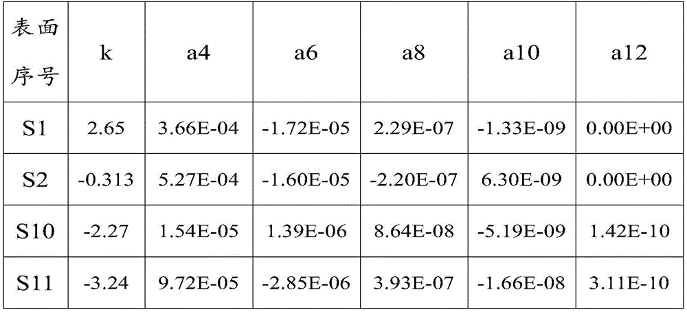
the focal length F of the telecentric projection lens is 6.30mm, the total length TTL is 37.8mm, and the aperture FNo.1.7, where the aperture is the reciprocal of the relative aperture. It should be noted that the relative aperture is the ratio of the diameter of the entrance pupil, which is the diameter of the diaphragm 4 imaged on the optical system in front of it, to the focal length.
Fig. 6 is a field curvature and distortion aberration diagram of a telecentric projection lens according to a second embodiment of the invention.
As shown in fig. 6, the field curvature of the telecentric projection lens provided by the second scene of the present embodiment is less than 0.05mm, and the maximum distortion is 1.0%.
Fig. 7 is a graph of MTF of a telecentric projection lens provided in a second embodiment of the invention.
As shown in fig. 7, the MTF of the full field of the telecentric projection lens provided by the second embodiment of the second embodiment is > 45% at the spatial frequency of 93 lp/mm.
Fig. 8 is a vertical axis chromatic aberration diagram of a telecentric projection lens provided in a second embodiment of the present invention.
As shown in FIG. 8, the vertical axis chromatic aberration of the imaging system is 4.0 μm at the maximum.
According to the parameters, the telecentric projection lens provided by the scene two has small distortion, excellent MTF performance, small vertical axis chromatic aberration, short focal length, strong resolving power, F1.7 aperture, excellent imaging quality and solves the problem of thermal defocusing to a certain degree.
Further, with respect to the telecentric projection lens provided by the above embodiment, which can be applied to an image output device, such as a desktop projector, a writing projector or other end products with projection function, a description of the image output device is given below as a possible implementation manner.
Fig. 9 is a schematic structural diagram of an image output apparatus according to an embodiment of the present invention.
As shown in fig. 9, the apparatus includes: telecentric projection lens 901, light source 903 and imaging element 902.
The light source is used for irradiating on the imaging element and projecting an image on the imaging element through the telecentric projection lens.
Optionally, the apparatus may further comprise: a processor, memory, radio frequency circuitry, and other associated input/output components for implementing the corresponding functions of the device, which are not limited herein.
The image output device uses the telecentric projection lens, so that the beneficial effects are similar to those of the telecentric projection lens, and the description is omitted.
The above description is only a preferred embodiment of the present invention and is not intended to limit the present invention, and various modifications and changes may be made by those skilled in the art. Any modification, equivalent replacement, or improvement made within the spirit and principle of the present invention should be included in the protection scope of the present invention.
Claims (7)
1. A telecentric projection lens, comprising:
the lens comprises a first lens group, a second lens group, a third lens group and a prism, wherein the first lens group is close to an object plane, the third lens group is close to an image plane, the second lens group is arranged between the first lens group and the third lens group, and the prism is arranged between the third lens group and the image plane;
the optical axes of the first lens group, the second lens group, the third lens group and the prism are coincident;
the first lens group has negative diopter, the second lens group has positive diopter, and the third lens group has positive diopter, wherein the first lens group, the second lens group, and the third lens group constitute a telecentric structure;
the first lens group includes:
the lens comprises a first negative meniscus lens and a second negative meniscus lens, wherein the first negative meniscus lens is arranged close to an object plane, and the second negative meniscus lens is arranged close to an image plane;
the first negative meniscus lens and the second negative meniscus lens have a negative refractive power;
the object side surface of the first negative meniscus lens is a convex surface, the image side surface of the first negative meniscus lens is a concave surface and both surfaces are aspheric surfaces;
the object space surface and the image space surface of the second negative meniscus lens are convex and concave, and are spherical;
the second lens group includes:
a first biconvex lens;
the first biconvex lens has positive diopter;
the object side surface and the image side surface of the first biconvex lens are both convex surfaces and both spherical surfaces;
the third lens group includes:
the optical lens comprises a first cemented lens and a second biconvex lens, wherein the first cemented lens is arranged close to an object plane, and the second biconvex lens is arranged close to an image plane;
the first cemented lens has negative diopter and comprises a first biconcave lens and a third biconvex lens, and the image side surface of the first biconcave lens is attached to the object side surface of the third biconvex lens;
the object side surface of the first biconcave lens, the image side surface of the third biconvex lens, and the joint surfaces of the first biconcave lens and the third biconvex lens are spherical surfaces;
the second biconvex lens has positive diopter, and the object side surface and the image side surface of the second biconvex lens are both convex surfaces and are both aspheric surfaces.
2. A telecentric projection lens of claim 1, further comprising an aperture stop disposed between the second lens group and the third lens group for controlling the throughput of light.
3. The telecentric projection lens of claim 2, further comprising a protective lens disposed between the prism and the image plane for protecting the imaging component disposed at the image plane.
4. A telecentric projection lens system as in claim 3, wherein 4.5< TTL/f <7.5, where TTL is the total lens length, representing the distance from the object surface to the image plane of the first lens group, and f is the effective focal length of the lens.
5. A telecentric projection lens as in claim 4, wherein BFL/f >2.2, wherein BFL is the back lens focal length, representing the distance from the image side surface of the third lens group to the image plane, and f is the effective lens focal length.
6. A telecentric projection lens of claim 1, wherein the distances between the first lens group, the second lens group, the third lens group and the image plane are adjusted to obtain a sharp image when the distance between the object plane and the telecentric projection lens is changed.
7. An image output apparatus comprising a telecentric projection lens according to any one of claims 1 to 6.
Priority Applications (1)
| Application Number | Priority Date | Filing Date | Title |
|---|---|---|---|
| CN201811485621.8A CN109270668B (en) | 2018-12-04 | 2018-12-04 | Telecentric projection lens and image output equipment |
Applications Claiming Priority (1)
| Application Number | Priority Date | Filing Date | Title |
|---|---|---|---|
| CN201811485621.8A CN109270668B (en) | 2018-12-04 | 2018-12-04 | Telecentric projection lens and image output equipment |
Publications (2)
| Publication Number | Publication Date |
|---|---|
| CN109270668A CN109270668A (en) | 2019-01-25 |
| CN109270668B true CN109270668B (en) | 2021-09-21 |
Family
ID=65186425
Family Applications (1)
| Application Number | Title | Priority Date | Filing Date |
|---|---|---|---|
| CN201811485621.8A Active CN109270668B (en) | 2018-12-04 | 2018-12-04 | Telecentric projection lens and image output equipment |
Country Status (1)
| Country | Link |
|---|---|
| CN (1) | CN109270668B (en) |
Families Citing this family (7)
| Publication number | Priority date | Publication date | Assignee | Title |
|---|---|---|---|---|
| CN110596854A (en) * | 2019-07-24 | 2019-12-20 | 浙江蓝特光学股份有限公司 | Optical system applied to vehicle-mounted projection lamp |
| CN110632741A (en) * | 2019-09-23 | 2019-12-31 | 深圳市点睛创视技术有限公司 | Projection lens |
| CN110579927B (en) * | 2019-10-09 | 2021-07-30 | 安徽仁和光电科技有限公司 | Small low-F-number high-definition projection lens |
| CN110989143A (en) * | 2020-01-03 | 2020-04-10 | 杭州有人光电技术有限公司 | Virtual object lighting lens with object space telecentric |
| CN213987007U (en) * | 2020-08-31 | 2021-08-17 | 深圳市光鉴科技有限公司 | Light Projector with Telecentric Lens |
| CN114690369B (en) * | 2020-12-25 | 2023-10-13 | 成都极米科技股份有限公司 | Projection lens |
| CN114019661B (en) * | 2021-12-07 | 2023-09-26 | 广东省科学院半导体研究所 | projection objective system |
Citations (1)
| Publication number | Priority date | Publication date | Assignee | Title |
|---|---|---|---|---|
| CN106154506A (en) * | 2015-03-30 | 2016-11-23 | 鸿富锦精密工业(深圳)有限公司 | Projection lens |
Family Cites Families (9)
| Publication number | Priority date | Publication date | Assignee | Title |
|---|---|---|---|---|
| JP2005164839A (en) * | 2003-12-01 | 2005-06-23 | Canon Inc | Lens system and image projection apparatus having the same |
| US7123426B2 (en) * | 2003-12-05 | 2006-10-17 | 3M Innovative Properties Company | Projection lens and display device |
| US7633688B2 (en) * | 2005-06-01 | 2009-12-15 | Olympus Imaging Corp. | Image forming optical system |
| JP5320224B2 (en) * | 2009-09-03 | 2013-10-23 | 富士フイルム株式会社 | Projection variable focus lens and projection display device |
| CN102455483B (en) * | 2010-10-20 | 2014-07-09 | 鸿富锦精密工业(深圳)有限公司 | Projection lens |
| CN102455489A (en) * | 2010-10-27 | 2012-05-16 | 鸿富锦精密工业(深圳)有限公司 | Projection lens |
| JP2016188893A (en) * | 2015-03-30 | 2016-11-04 | 日立マクセル株式会社 | Imaging lens system and imaging apparatus |
| CN107153265A (en) * | 2017-07-03 | 2017-09-12 | 松林光电科技(湖北)有限公司 | The varifocal DLP types digital projection camera lens of telecentricity type large aperture |
| CN209044168U (en) * | 2018-11-01 | 2019-06-28 | 北京乐都展陈科技发展有限公司 | A kind of projection lens |
-
2018
- 2018-12-04 CN CN201811485621.8A patent/CN109270668B/en active Active
Patent Citations (1)
| Publication number | Priority date | Publication date | Assignee | Title |
|---|---|---|---|---|
| CN106154506A (en) * | 2015-03-30 | 2016-11-23 | 鸿富锦精密工业(深圳)有限公司 | Projection lens |
Also Published As
| Publication number | Publication date |
|---|---|
| CN109270668A (en) | 2019-01-25 |
Similar Documents
| Publication | Publication Date | Title |
|---|---|---|
| CN109270668B (en) | Telecentric projection lens and image output equipment | |
| CN106353877B (en) | Optical imaging system | |
| CN107203030B (en) | Optical imaging system | |
| CN108279480B (en) | Optical imaging system | |
| CN109307923B (en) | Optical imaging system | |
| CN114859559A (en) | Optical lens | |
| CN107272147B (en) | optical imaging system | |
| CN107045179A (en) | Optical imaging system | |
| TWI695993B (en) | Fixed focus lens | |
| CN107272146B (en) | optical imaging system | |
| CN106896480B (en) | Telecentric zoom lens of projector | |
| CN110275274B (en) | Optical imaging system | |
| CN107589520A (en) | Optical imaging system | |
| CN106842498A (en) | Optical imaging system | |
| CN114509860B (en) | Projection lens and projection equipment | |
| CN109298584B (en) | Projection lens and projector | |
| CN206074892U (en) | Focus lens in a kind of long-focus | |
| CN107229103A (en) | Optical imaging system | |
| CN109254387B (en) | Projection lens and image output apparatus | |
| CN111638588B (en) | Optical zoom system, lens and video camera | |
| CN114253053B (en) | Projection lens and projection equipment | |
| TWI831882B (en) | Zoom projection lens | |
| US2889745A (en) | Wide angle attachment for objective lenses | |
| CN115453716B (en) | Optical projection system and projection device | |
| CN216748252U (en) | Optical imaging system |
Legal Events
| Date | Code | Title | Description |
|---|---|---|---|
| PB01 | Publication | ||
| PB01 | Publication | ||
| SE01 | Entry into force of request for substantive examination | ||
| SE01 | Entry into force of request for substantive examination | ||
| GR01 | Patent grant | ||
| GR01 | Patent grant | ||
| TR01 | Transfer of patent right |
Effective date of registration: 20220113 Address after: 609, 6th floor, building 1, Saiba science and technology building, no.6, Langshan 2nd Road, songpingshan community, Xili street, Nanshan District, Shenzhen, Guangdong 518000 Patentee after: Shenzhen Xiaoxiang light display Co.,Ltd. Address before: 518000 511 Saiba electronics, No.16, Beier Road, Science Park, Yuehai street, Nanshan District, Shenzhen City, Guangdong Province Patentee before: ELEPN PROJECTION DISPLAY TECHNOLOGY CO.,LTD. |
|
| TR01 | Transfer of patent right |