CN109228317B - Changeable facula mirror holder structure of SLA 3D printer - Google Patents
Changeable facula mirror holder structure of SLA 3D printer Download PDFInfo
- Publication number
- CN109228317B CN109228317B CN201811219055.6A CN201811219055A CN109228317B CN 109228317 B CN109228317 B CN 109228317B CN 201811219055 A CN201811219055 A CN 201811219055A CN 109228317 B CN109228317 B CN 109228317B
- Authority
- CN
- China
- Prior art keywords
- lens
- mirror
- screw
- plate
- sla
- Prior art date
- Legal status (The legal status is an assumption and is not a legal conclusion. Google has not performed a legal analysis and makes no representation as to the accuracy of the status listed.)
- Active
Links
Images


Classifications
-
- B—PERFORMING OPERATIONS; TRANSPORTING
- B29—WORKING OF PLASTICS; WORKING OF SUBSTANCES IN A PLASTIC STATE IN GENERAL
- B29C—SHAPING OR JOINING OF PLASTICS; SHAPING OF MATERIAL IN A PLASTIC STATE, NOT OTHERWISE PROVIDED FOR; AFTER-TREATMENT OF THE SHAPED PRODUCTS, e.g. REPAIRING
- B29C64/00—Additive manufacturing, i.e. manufacturing of three-dimensional [3D] objects by additive deposition, additive agglomeration or additive layering, e.g. by 3D printing, stereolithography or selective laser sintering
- B29C64/10—Processes of additive manufacturing
- B29C64/106—Processes of additive manufacturing using only liquids or viscous materials, e.g. depositing a continuous bead of viscous material
- B29C64/124—Processes of additive manufacturing using only liquids or viscous materials, e.g. depositing a continuous bead of viscous material using layers of liquid which are selectively solidified
- B29C64/129—Processes of additive manufacturing using only liquids or viscous materials, e.g. depositing a continuous bead of viscous material using layers of liquid which are selectively solidified characterised by the energy source therefor, e.g. by global irradiation combined with a mask
- B29C64/135—Processes of additive manufacturing using only liquids or viscous materials, e.g. depositing a continuous bead of viscous material using layers of liquid which are selectively solidified characterised by the energy source therefor, e.g. by global irradiation combined with a mask the energy source being concentrated, e.g. scanning lasers or focused light sources
-
- B—PERFORMING OPERATIONS; TRANSPORTING
- B29—WORKING OF PLASTICS; WORKING OF SUBSTANCES IN A PLASTIC STATE IN GENERAL
- B29C—SHAPING OR JOINING OF PLASTICS; SHAPING OF MATERIAL IN A PLASTIC STATE, NOT OTHERWISE PROVIDED FOR; AFTER-TREATMENT OF THE SHAPED PRODUCTS, e.g. REPAIRING
- B29C64/00—Additive manufacturing, i.e. manufacturing of three-dimensional [3D] objects by additive deposition, additive agglomeration or additive layering, e.g. by 3D printing, stereolithography or selective laser sintering
- B29C64/20—Apparatus for additive manufacturing; Details thereof or accessories therefor
- B29C64/264—Arrangements for irradiation
-
- B—PERFORMING OPERATIONS; TRANSPORTING
- B33—ADDITIVE MANUFACTURING TECHNOLOGY
- B33Y—ADDITIVE MANUFACTURING, i.e. MANUFACTURING OF THREE-DIMENSIONAL [3-D] OBJECTS BY ADDITIVE DEPOSITION, ADDITIVE AGGLOMERATION OR ADDITIVE LAYERING, e.g. BY 3-D PRINTING, STEREOLITHOGRAPHY OR SELECTIVE LASER SINTERING
- B33Y30/00—Apparatus for additive manufacturing; Details thereof or accessories therefor
Landscapes
- Chemical & Material Sciences (AREA)
- Engineering & Computer Science (AREA)
- Materials Engineering (AREA)
- Physics & Mathematics (AREA)
- Optics & Photonics (AREA)
- Manufacturing & Machinery (AREA)
- Mechanical Engineering (AREA)
- Health & Medical Sciences (AREA)
- Toxicology (AREA)
- Lens Barrels (AREA)
Abstract
The invention discloses a variable facula mirror bracket structure of an SLA 3D printer, which comprises a support, a left adjusting plate and a right adjusting plate, wherein the left adjusting plate and the right adjusting plate are installed at the lower end of the support through a screw M4X25, a dimming bottom plate is installed at the lower end of the left adjusting plate and the right adjusting plate through a screw M5X35, a lens barrel fixing plate, an idler wheel seat and a stepping motor are sequentially installed on the bottom surface of the dimming bottom plate, a lens barrel is fixedly installed at the lower end of the lens barrel fixing plate, a convex lens and a concave lens are installed at one end inside the lens barrel, a movable lens sleeve is installed at the other end of the inside of the lens barrel on the movable lens sleeve through a linear bearing, a; step motor and last all transmission connection of idler seat install the synchronizing wheel, and the transmission is installed annular belt between two synchronizing wheels, the downside of annular belt and the top fixed connection who removes the post. The invention uses the series combination structure of the concave mirror, the convex mirror and the extended mirror to adjust the size of the light spot, and the adjustment precision is high.
Description
Technical Field
The invention relates to a variable light spot mirror frame structure, in particular to a variable light spot mirror frame structure of an SLA 3D printer, and belongs to the technical field of printing equipment.
Background
The variable spot structure on the market at present uses a single lens structure: when the big and small light spots change, the electric cylinder is used for driving the mirror expanding to stretch and intervene in the light path, when the light spots are enlarged, the mirror expanding can enlarge the light spots, and when the light spots are reduced, the mirror expanding is evacuated to restore the light spots to be reduced. The structure has low positioning precision and concentricity when adjusting the light spot, and the printing precision is poor because the light spot positioning changes when the size is changed and the light spot is switched. When a large light spot is switched, the light transmittance of one expanding mirror is increased, and the light transmittance is lost, so that the power is unstable when the large light spot is changed, and the quality of the printed surface is poor.
In order to overcome the defects of poor positioning precision, low concentricity and unstable power in light spot switching, the light spot size is adjusted by using a concave-convex lens and mirror expanding series combination structure, and the mirror bracket adopts a combination of a three-point plane spring and a side surface right-left spring to adjust the light path concentricity.
Disclosure of Invention
The technical problem to be solved by the invention is to overcome the defects that the positioning precision and concentricity are low when the light spot is adjusted by a variable light spot structure on the market at present, and the printing precision is poor due to the fact that the light spot positioning changes when the size is changed and the light spot is switched, and provide a variable light spot mirror bracket structure of an SLA 3D printer.
In order to solve the technical problems, the invention provides the following technical scheme:
the invention provides a variable light spot mirror frame structure of an SLA 3D printer, which comprises a lens cone, a dimming bottom plate, a support and a left and right adjusting plate, wherein the lower end of the support is provided with the left and right adjusting plate through a screw M4X25, the two ends of the left and right adjusting plate are respectively provided with a long-strip-shaped screw hole for mounting a screw M4X25, the two ends of the side surface of the left and right adjusting plate are respectively provided with a screw M5X40, a spring is clamped and sleeved between the screw M5X40 and the left and right adjusting plate, the lower end of the left and right adjusting plate is provided with the dimming bottom plate through a screw M5X35, a spring is sleeved on the screw M5X35 and clamped between the bottom surface of the left and right adjusting plate and the top surface of the dimming bottom plate, the bottom surface of the dimming bottom plate is sequentially provided with a lens cone fixing plate, an idler, the other end of the movable mirror sleeve is provided with a movable mirror sleeve through a linear bearing, one end of the movable mirror sleeve, which is positioned in the lens cone, is provided with a movable mirror expander, the upper end of the linear bearing is fixedly provided with a movable column, and the upper end of the movable column penetrates through the lens cone and is positioned on the outer side above the lens cone; step motor and idler seat are gone up equal transmission connection and are installed the synchronizing wheel, and the transmission is installed annular belt between two synchronizing wheels, the downside of annular belt and the top fixed connection who removes the post.
As a preferred technical solution of the present invention, the bottom surface of the light adjusting bottom plate is provided with a limit stop piece located at one side of the moving column.
As a preferable technical scheme of the invention, spring blocking sheets are arranged at two ends of the spring.
As a preferred technical scheme of the invention, the outer diameters of the convex mirror and the concave mirror are matched and locked with the inner hole of the lens cone in a taper way.
As a preferable technical solution of the present invention, an outer diameter of the linear bearing is interference-fitted with an inner diameter of the lens barrel.
The invention has the following beneficial effects: the three lenses are sleeved in the same lens cone, so that the coaxiality of the three lenses is ensured; the movable extended mirror is sleeved on the inner diameter of the linear bearing, and the outer diameter of the linear bearing is in interference fit with the inner hole of the lens cone, so that the movable extended mirror can coaxially move with the concave mirror of the convex mirror; the springs are adjustable, so that the lens barrel can be adjusted in multiple dimensions, and the position of the lens barrel is located on the optimal coaxial line of the optical path.
Drawings
The accompanying drawings, which are included to provide a further understanding of the invention and are incorporated in and constitute a part of this specification, illustrate embodiments of the invention and together with the description serve to explain the principles of the invention and not to limit the invention. In the drawings:
FIG. 1 is a schematic structural view of the present invention;
FIG. 2 is a cross-sectional view taken along plane A-A of FIG. 1 in accordance with the present invention;
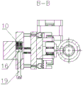
FIG. 3 is a cross-sectional view taken along line B-B of FIG. 1 in accordance with the present invention;
in the figure: 1. the device comprises a lens barrel, a dimming bottom plate, a support, a lens barrel fixing plate, a left adjusting plate, a right adjusting plate, a movable extended mirror, a convex mirror, a concave mirror, a movable mirror sleeve, a spring, a idler wheel seat, a synchronous wheel, a ring-shaped belt, a stepping motor, a linear bearing, a spring baffle, a photoelectric switch, a limit baffle, a screw M5X40, a screw M5X35, a screw M4X25 and a screw M22, wherein the movable extended mirror is arranged on the lens barrel, the convex mirror is arranged on the lens barrel, the concave mirror is arranged on the lens barrel, the movable mirror sleeve is arranged on the lens barrel, the spring is arranged on.
Detailed Description
The preferred embodiments of the present invention will be described in conjunction with the accompanying drawings, and it will be understood that they are described herein for the purpose of illustration and explanation and not limitation.
Example 1
As shown in fig. 1-3, the present invention provides a variable light spot mirror holder structure of SLA 3D printer, comprising a lens barrel 1, a light adjusting base plate 2, a support 3, a left and right adjusting plate 5, wherein the lower end of the support 3 is provided with the left and right adjusting plate 5 through a screw M4X 2521, two ends of the left and right adjusting plate 5 are respectively provided with a long strip screw hole for mounting the screw M4X 2521, two ends of a side surface of the left and right adjusting plate 5 are respectively provided with a screw M5X 4019, a spring 10 is clamped and sleeved between the screw M5X 4019 and the left and right adjusting plate 5, the lower end of the left and right adjusting plate 5 is provided with the light adjusting base plate 2 through a screw M5X 3520, the screw M5X 3520 is sleeved with a spring 10, the spring 10 is clamped and positioned between the bottom surface of the left and right adjusting plate 5 and the top surface of the light adjusting base plate 2, a convex mirror 7 and a concave mirror 8 are arranged at one end inside the lens cone 1, a movable mirror sleeve 9 is arranged at the other end through a linear bearing 15, a movable mirror expanding mirror 6 is arranged at one end, positioned inside the lens cone 1, on the movable mirror sleeve 9, a movable column 22 is fixedly arranged at the upper end of the linear bearing 15, and the upper end of the movable column 22 penetrates through the lens cone 1 and is positioned on the outer side above the lens cone 1; synchronous wheels 12 are arranged on the stepping motor 14 and the idler wheel seat 11 in a transmission connection mode, an annular belt 13 is arranged between the two synchronous wheels 12 in a transmission mode, and the lower side face of the annular belt 13 is fixedly connected with the top end of the movable column 22.
The bottom surface of the light adjusting bottom plate 2 is provided with a limit stop piece 18 positioned at one side of the moving column 22 to prevent the moving column 22 from excessively displacing. Spring 10 is provided with spring stops 16 at each end to prevent the spring from impressing the contact surface of the object at each end. The outer diameters of the convex mirror 7 and the concave mirror 8 are matched and locked with the inner hole taper of the lens cone 1. The outer diameter of the linear bearing 15 is interference-fitted with the inner diameter of the lens barrel 1.
The specific working principle is as follows: in the invention, the outer diameters of a convex mirror 7 and a concave mirror 8 are matched and locked with the inner hole of a lens barrel 1 in a taper fit manner, so that the concentricity of the two lenses and the lens barrel 1 is ensured, the movable expanding mirror 6 and a movable mirror sleeve 9 are mutually sleeved in the inner hole of the lens barrel 1 along with the inner diameter and the outer diameter of a linear bearing 15, and the coaxiality of the movable expanding mirror 6 and the convex mirror 7 and the concave mirror 8 as well as the relative front-back coaxial sliding of the movable expanding mirror 6 and the convex mirror 7 and the concave mirror; the stepping motor 14 drives the synchronizing wheel 12 to rotate, the annular belt 13 is pulled, the annular belt 13 drives the movable mirror expanding 6 assembly to move back and forth through the moving column 22, and the change switching of the large and small light spots is realized.
The lens cone 1 is fixed on the lens cone fixing plate 4, the lens cone fixing plate 4 is connected with the dimming bottom plate 2, the dimming bottom plate 2 is connected with a left-right adjusting plate through a spring 10 and a screw M5X35, the lens cone 1 can be adjusted up and down and in an inclined mode through an adjusting screw M5X35, the left-right adjusting plate 5 is connected with the spring 10 and a screw M5X40 in a clamping mode, the lens cone 1 can be adjusted left and right and in an inclined mode through an adjusting screw M5X40, and the position of the lens cone 1 is located on.
The invention has the following beneficial effects: the three lenses are sleeved in the same lens cone, so that the coaxiality of the three lenses is ensured; the movable extended mirror is sleeved on the inner diameter of the linear bearing, and the outer diameter of the linear bearing is in interference fit with the inner hole of the lens cone, so that the movable extended mirror can coaxially move with the concave mirror of the convex mirror; the springs are adjustable, so that the lens barrel can be adjusted in multiple dimensions, and the position of the lens barrel is located on the optimal coaxial line of the optical path.
Finally, it should be noted that: although the present invention has been described in detail with reference to the foregoing embodiments, it will be apparent to those skilled in the art that changes may be made in the embodiments and/or equivalents thereof without departing from the spirit and scope of the invention. Any modification, equivalent replacement, or improvement made within the spirit and principle of the present invention should be included in the protection scope of the present invention.
Claims (5)
1. The utility model provides a changeable facula mirror holder structure of SLA 3D printer, includes lens cone (1), adjusts luminance bottom plate (2), support (3) and controls regulating plate (5), its characterized in that, regulating plate (5) about the lower extreme of support (3) is installed through screw M4X25 (21), just the both ends of controlling regulating plate (5) all are provided with the rectangular shape screw hole that is used for installing screw M4X25 (21), screw M5X40 (19) are all installed to the both ends of controlling regulating plate (5) side, the clamp sleeve is equipped with spring (10) between screw M5X40 (19) and the controlling regulating plate (5), the lower extreme of controlling regulating plate (5) passes through screw M5X35 (20) and installs the bottom plate (2) of adjusting luminance about, the cover is equipped with spring (10) on screw M5X35 (20), and spring (10) clamp is located between the bottom surface of controlling regulating plate (5) and the top surface of adjusting plate (2) of adjusting luminance, the bottom surface of the dimming bottom plate (2) is sequentially provided with a lens cone fixing plate (4), an idler pulley seat (11) and a stepping motor (14), the lower end of the lens cone fixing plate (4) is fixedly provided with a lens cone (1), one end of the interior of the lens cone (1) is provided with a convex lens (7) and a concave lens (8), the other end of the interior of the lens cone (1) is provided with a movable lens sleeve (9) through a linear bearing (15), one end of the movable lens sleeve (9) located in the interior of the lens cone (1) is provided with a movable extended lens (6), the upper end of the linear bearing (15) is fixedly provided with a movable column (22), and the upper end of the movable column (22) penetrates through the outside; step motor (14) and idler seat (11) are gone up equal transmission connection and are installed synchronizing wheel (12), and endless belt (13) are installed in the transmission between two synchronizing wheel (12), the downside of endless belt (13) and the top fixed connection who removes post (22).
2. An SLA 3D printer variable spot mirror bracket structure according to claim 1, characterised in that the bottom surface of the dimming bottom plate (2) is provided with a limit stop (18) on one side of the moving post (22).
3. An SLA 3D printer variable spot mirror bracket structure according to claim 1, characterised in that spring catches (16) are mounted at both ends of the spring (10).
4. The SLA 3D printer variable spot mirror bracket structure according to claim 1, characterized in that the outer diameters of the convex mirror (7) and the concave mirror (8) are locked with the inner hole of the lens barrel (1) in a taper fit manner.
5. The SLA 3D printer variable spot mirror bracket structure according to claim 1, characterized in that the outer diameter of the linear bearing (15) is interference fit with the inner diameter of the lens barrel (1).
Priority Applications (1)
| Application Number | Priority Date | Filing Date | Title |
|---|---|---|---|
| CN201811219055.6A CN109228317B (en) | 2018-10-19 | 2018-10-19 | Changeable facula mirror holder structure of SLA 3D printer |
Applications Claiming Priority (1)
| Application Number | Priority Date | Filing Date | Title |
|---|---|---|---|
| CN201811219055.6A CN109228317B (en) | 2018-10-19 | 2018-10-19 | Changeable facula mirror holder structure of SLA 3D printer |
Publications (2)
| Publication Number | Publication Date |
|---|---|
| CN109228317A CN109228317A (en) | 2019-01-18 |
| CN109228317B true CN109228317B (en) | 2020-08-21 |
Family
ID=65053697
Family Applications (1)
| Application Number | Title | Priority Date | Filing Date |
|---|---|---|---|
| CN201811219055.6A Active CN109228317B (en) | 2018-10-19 | 2018-10-19 | Changeable facula mirror holder structure of SLA 3D printer |
Country Status (1)
| Country | Link |
|---|---|
| CN (1) | CN109228317B (en) |
Citations (6)
| Publication number | Priority date | Publication date | Assignee | Title |
|---|---|---|---|---|
| US20100228369A1 (en) * | 2007-10-10 | 2010-09-09 | Materialise Nv | Method and apparatus for automatic support generation for an object made by means of a rapid prototype production method |
| CN205539735U (en) * | 2016-01-25 | 2016-08-31 | 东莞市鸿泰自动化设备有限公司 | A laser spot size automatic regulating apparatus for printer |
| CN205522519U (en) * | 2016-01-25 | 2016-08-31 | 东莞市鸿泰自动化设备有限公司 | A variable facula controlling means for printer |
| CN206085681U (en) * | 2016-10-10 | 2017-04-12 | 深圳市金石三维打印科技有限公司 | 3D printing apparatus becomes facula mechanism |
| CN207432803U (en) * | 2017-08-18 | 2018-06-01 | 佛山吗卡工程技术有限公司 | A kind of optical path adjusting component for laser 3D printing machine adjustable spot size |
| CN207724853U (en) * | 2017-06-29 | 2018-08-14 | 深圳市金石三维打印科技有限公司 | A kind of hot spot automatic adjusting mechanism and SLA light-cured resin printers |
-
2018
- 2018-10-19 CN CN201811219055.6A patent/CN109228317B/en active Active
Patent Citations (6)
| Publication number | Priority date | Publication date | Assignee | Title |
|---|---|---|---|---|
| US20100228369A1 (en) * | 2007-10-10 | 2010-09-09 | Materialise Nv | Method and apparatus for automatic support generation for an object made by means of a rapid prototype production method |
| CN205539735U (en) * | 2016-01-25 | 2016-08-31 | 东莞市鸿泰自动化设备有限公司 | A laser spot size automatic regulating apparatus for printer |
| CN205522519U (en) * | 2016-01-25 | 2016-08-31 | 东莞市鸿泰自动化设备有限公司 | A variable facula controlling means for printer |
| CN206085681U (en) * | 2016-10-10 | 2017-04-12 | 深圳市金石三维打印科技有限公司 | 3D printing apparatus becomes facula mechanism |
| CN207724853U (en) * | 2017-06-29 | 2018-08-14 | 深圳市金石三维打印科技有限公司 | A kind of hot spot automatic adjusting mechanism and SLA light-cured resin printers |
| CN207432803U (en) * | 2017-08-18 | 2018-06-01 | 佛山吗卡工程技术有限公司 | A kind of optical path adjusting component for laser 3D printing machine adjustable spot size |
Also Published As
| Publication number | Publication date |
|---|---|
| CN109228317A (en) | 2019-01-18 |
Similar Documents
| Publication | Publication Date | Title |
|---|---|---|
| CN109228317B (en) | Changeable facula mirror holder structure of SLA 3D printer | |
| CN208477271U (en) | It is a kind of based on servo motor realize can continuous vari-focus laser illuminator | |
| CN208418576U (en) | A kind of automobile lamp dimming light source mechanism | |
| CN109668122B (en) | Lead screw motor zoom control device of stage lamp | |
| CN113028326A (en) | A wire casing lamp that is used for rail vehicle's ability to adjust luminous angle | |
| CN112936042A (en) | Spare part grinding device is used in production of planar transformer | |
| CN205424590U (en) | Shot -light of adjustable light ring size | |
| CN1034887C (en) | microscope stand | |
| CN205316183U (en) | Spot lamp | |
| CN209604861U (en) | Photographic equipment and its shoulder-supporting type camera mounting | |
| CN212890989U (en) | Optical lens fixing device for high-definition aerial photography instrument | |
| CN212723491U (en) | Optical lens and imaging device | |
| CN211680490U (en) | Portable electric welding machine | |
| CN220232210U (en) | Multi-camera and light supplementing device thereof | |
| CN204020497U (en) | A kind of anti-dazzle mirrror | |
| CN218064601U (en) | Adjustable LED ceiling lamp | |
| CN220584469U (en) | Optical element adjusting device | |
| CN212256687U (en) | Combined optical mirror device for college physics experiments | |
| CN219473477U (en) | Ultrathin LED car light source bracket | |
| CN220446182U (en) | Lens clamping device for sunglasses processing | |
| US10241271B2 (en) | Windproof cover unit for optical fiber fusion splicer | |
| CN221171974U (en) | Light guide strip of atmosphere lamp | |
| CN212901012U (en) | Variable-focus lamp module with easily-replaceable lens | |
| CN214948563U (en) | But rotation regulation's line lamp | |
| CN218380667U (en) | Zoom cam barrel of sighting device |
Legal Events
| Date | Code | Title | Description |
|---|---|---|---|
| PB01 | Publication | ||
| PB01 | Publication | ||
| SE01 | Entry into force of request for substantive examination | ||
| SE01 | Entry into force of request for substantive examination | ||
| GR01 | Patent grant | ||
| GR01 | Patent grant | ||
| CP03 | Change of name, title or address |
Address after: 518000 Floor 1-4, No. 5, Longfu Industrial Zone, Huarong Road, Henglang Community, Dalang Street, Longhua District, Shenzhen City, Guangdong Province Patentee after: Shenzhen Aurora Innovation Technology Co.,Ltd. Address before: 518000 5 / F, building 1, Longquan science and Technology Industrial Park, Tongsheng community, Dalang street, Longhua District, Shenzhen City, Guangdong Province Patentee before: SHENZHEN AURORA TECHNOLOGY CO.,LTD. |
|
| CP03 | Change of name, title or address |