CN109155949B - Method and device for interworking between networks in wireless communication - Google Patents
Method and device for interworking between networks in wireless communication Download PDFInfo
- Publication number
- CN109155949B CN109155949B CN201880002078.3A CN201880002078A CN109155949B CN 109155949 B CN109155949 B CN 109155949B CN 201880002078 A CN201880002078 A CN 201880002078A CN 109155949 B CN109155949 B CN 109155949B
- Authority
- CN
- China
- Prior art keywords
- network
- epc
- procedure
- mme
- handover
- Prior art date
- Legal status (The legal status is an assumption and is not a legal conclusion. Google has not performed a legal analysis and makes no representation as to the accuracy of the status listed.)
- Active
Links
Images


Classifications
-
- H—ELECTRICITY
- H04—ELECTRIC COMMUNICATION TECHNIQUE
- H04W—WIRELESS COMMUNICATION NETWORKS
- H04W92/00—Interfaces specially adapted for wireless communication networks
- H04W92/02—Inter-networking arrangements
-
- H—ELECTRICITY
- H04—ELECTRIC COMMUNICATION TECHNIQUE
- H04W—WIRELESS COMMUNICATION NETWORKS
- H04W12/00—Security arrangements; Authentication; Protecting privacy or anonymity
- H04W12/60—Context-dependent security
- H04W12/69—Identity-dependent
- H04W12/72—Subscriber identity
-
- H—ELECTRICITY
- H04—ELECTRIC COMMUNICATION TECHNIQUE
- H04W—WIRELESS COMMUNICATION NETWORKS
- H04W36/00—Hand-off or reselection arrangements
- H04W36/0005—Control or signalling for completing the hand-off
- H04W36/0011—Control or signalling for completing the hand-off for data sessions of end-to-end connection
-
- H—ELECTRICITY
- H04—ELECTRIC COMMUNICATION TECHNIQUE
- H04W—WIRELESS COMMUNICATION NETWORKS
- H04W36/00—Hand-off or reselection arrangements
- H04W36/14—Reselecting a network or an air interface
- H04W36/144—Reselecting a network or an air interface over a different radio air interface technology
-
- H—ELECTRICITY
- H04—ELECTRIC COMMUNICATION TECHNIQUE
- H04W—WIRELESS COMMUNICATION NETWORKS
- H04W8/00—Network data management
- H04W8/02—Processing of mobility data, e.g. registration information at HLR [Home Location Register] or VLR [Visitor Location Register]; Transfer of mobility data, e.g. between HLR, VLR or external networks
-
- H—ELECTRICITY
- H04—ELECTRIC COMMUNICATION TECHNIQUE
- H04W—WIRELESS COMMUNICATION NETWORKS
- H04W36/00—Hand-off or reselection arrangements
- H04W36/0005—Control or signalling for completing the hand-off
- H04W36/0055—Transmission or use of information for re-establishing the radio link
- H04W36/0066—Transmission or use of information for re-establishing the radio link of control information between different types of networks in order to establish a new radio link in the target network
-
- H—ELECTRICITY
- H04—ELECTRIC COMMUNICATION TECHNIQUE
- H04W—WIRELESS COMMUNICATION NETWORKS
- H04W60/00—Affiliation to network, e.g. registration; Terminating affiliation with the network, e.g. de-registration
-
- H—ELECTRICITY
- H04—ELECTRIC COMMUNICATION TECHNIQUE
- H04W—WIRELESS COMMUNICATION NETWORKS
- H04W60/00—Affiliation to network, e.g. registration; Terminating affiliation with the network, e.g. de-registration
- H04W60/06—De-registration or detaching
Landscapes
- Engineering & Computer Science (AREA)
- Computer Networks & Wireless Communication (AREA)
- Signal Processing (AREA)
- Databases & Information Systems (AREA)
- Computer Security & Cryptography (AREA)
- Mobile Radio Communication Systems (AREA)
Abstract
One aspect of the present invention relates to a method of interworking between networks of terminals in a wireless communication system, the method comprising the steps of: performing a first interworking procedure for changing a network of the terminal from a 5-generation core network (5GC) network to an Evolved Packet Core (EPC) network, wherein the step of performing the first interworking procedure may include the steps of: receiving a first indication of an access and mobility management function (AMF) from a 5GC network if an interface does not exist between the 5GC and an EPC network; and performing a handover attach procedure in the EPC network based on the first indication.
Description
Technical Field
The present invention relates to wireless communication, and more particularly, to an interworking method between networks and an apparatus for the same.
Background
A mobile communication system has been developed to provide voice services while guaranteeing user activities. However, the mobile communication system expands the area to data services as well as voice, and currently, a shortage phenomenon of resources is caused due to explosive increase of traffic and a service requiring higher speed is used, and as a result, a more developed mobile communication system is required.
The requirements of the next generation mobile communication systems are mainly to support the accommodation of explosive data traffic, epoch-making increase of transmission rate per user, significant increase of the number of connected devices, very low end-to-end delay, and high energy efficiency. To this end, various technologies have been investigated, including dual connectivity, massive Multiple Input Multiple Output (MIMO), in-band full duplex, non-orthogonal multiple access (NOMA), ultra-wideband support, device networking, and so on.
In particular, for devices whose power consumption significantly affects the lifetime of the device, various techniques for reducing power consumption have been vigorously developed.
Disclosure of Invention
Technical problem
The present invention proposes a method of efficiently performing an interworking procedure between an EPC and a 5G core network in a wireless communication system. In particular, the present invention proposes a solution in relation to a network node in order to reduce the load imposed on a User Equipment (UE) during interworking.
Embodiments of methods and apparatuses for solving the above technical problems are provided. It is to be understood that both the foregoing general description and the following detailed description are exemplary and explanatory and are not restrictive of the invention, as defined by the appended claims and their equivalents.
Technical scheme
According to an aspect of the present invention, there is provided an interworking method between networks of User Equipments (UEs) in a wireless communication system, including: performing a first interworking procedure for changing a network of the UE from a 5-generation core network (5GC) network to an Evolved Packet Core (EPC) network, wherein when an interface between the 5GC and the EPC network does not exist, performing the first interworking procedure includes: receiving a first indication from an access and mobility management function (AMF) of the 5GC network; and performing a handover attach procedure in the EPC network based on the first indication.
Performing the first interworking procedure may include not receiving the first indication from the AMF when an interface between the 5GC and the EPC network exists, and performing a Tracking Area Update (TAU) procedure in the EPC network.
A Packet Data Unit (PDU) session generated for the UE in the 5GC may be transferred to the EPC network through a handover attach procedure or a TAU procedure.
Performing the handover attach procedure may include: sending a PDN connection request message, wherein the request type is set to a Mobility Management Entity (MME) of the EPC.
The interworking method may further include: information indicating that the UE moves from 5GC is transmitted to the MME.
The EPC may have an EPC-GUTI mapped with a globally unique temporary user equipment identification (GUTI) of 5 GC.
The interworking method may further include: when an interface between the 5GC and the EPC network does not exist and the UE is in a connected mode in the 5GC, Radio Resource Control (RRC) release is performed with "Next Generation (NG)" - "Radio Access Network (RAN)" of the 5GC and camped on a cell connected to the EPC.
The interworking method may further include: performing a second interworking procedure for changing a network of the UE from the EPC network to the 5GC network, wherein when an interface between the 5GC and the EPC network does not exist, performing the second interworking procedure includes: receiving a second indication from a Mobility Management Entity (MME) of the EPC network; and performing a registration procedure in the 5GC network based on the second indication.
A Packet Data Unit (PDU) session generated for the UE in the EPC may be transferred to the 5GC network through a registration procedure.
The registration procedure may be a registration procedure in which the registration type is set to mobility registration update.
The interworking method may further include: information indicating that the UE moves from the EPC is transmitted to the AMF.
The 5GC may have a 5GC-GUTI mapped with a globally unique temporary user equipment identification (GUTI) of the EPC.
The interworking method may further include: when the interface between the 5GC and the EPC network does not exist and the UE is in connected mode in the EPC: radio Resource Control (RRC) release is performed using the evolved Universal terrestrial radio Access network (E-UTRAN) of the EPC.
According to another aspect of the present invention, there is provided a User Equipment (UE) performing an interworking method between networks in a wireless communication system, comprising: a communication module configured to transmit and receive a signal; a processor configured to control the communication module, wherein the processor is configured to: performing a first interworking procedure for changing a network of the UE from a5 generation core network (5GC) network to an Evolved Packet Core (EPC) network, receiving an indication of an access and mobility management function (AMF) from the 5GC network when an interface between the 5GC and the EPC network does not exist; and performing a handover attach procedure in the EPC network based on the indication.
When an interface between the 5GC and the EPC network exists, the processor may not receive an indication from the AMF and may perform a Tracking Area Update (TAU) procedure in the EPC.
Advantageous effects
According to one or more embodiments of the present invention, since the interworking procedure between networks is clearly defined, ambiguity in the execution of the procedure is eliminated.
Further, according to one or more embodiments of the present invention, since a network node instructs a User Equipment (UE) whether to perform a TAU or a handover attach/registration procedure in order to interwork with each other, a burden of the UE is reduced, and a service interruption time due to interworking is reduced by appropriately performing the TAU.
The effects obtained by the present invention are not limited to the above-described effects, and other effects not mentioned can be clearly understood by those skilled in the art from the following description.
Drawings
The accompanying drawings, which are included to provide a further understanding of the invention as a part of the detailed description, illustrate embodiments of the invention and together with the description serve to explain the technical principles of the invention.
Fig. 1 shows an Evolved Packet System (EPS) to which the present invention can be applied.
Fig. 2 shows an example of an evolved universal terrestrial radio access network (E-UTRAN) to which the present invention can be applied.
Fig. 3 shows the structure of an E-UTRAN and an EPC in a wireless communication system to which the present invention can be applied.
Fig. 4 illustrates a radio interface protocol structure between a UE and an E-UTRAN in a wireless communication system to which the present invention can be applied.
Fig. 5 shows an S1 interface protocol structure in a wireless communication system to which the present invention can be applied.
Fig. 6 shows a physical channel structure in a wireless communication system to which the present invention can be applied.
Fig. 7 shows EMM and ECM states in a wireless communication system to which the present invention can be applied.
Fig. 8 illustrates a contention-based random access procedure in a wireless communication system to which the present invention can be applied.
Fig. 9 shows a 5G system architecture using a reference point representation.
Fig. 10 illustrates a 5G system architecture using a service-based representation.
Fig. 11 shows a NG-RAN architecture to which the present invention can be applied.
Fig. 12 shows a radio protocol stack to which the present invention can be applied.
FIG. 13 illustrates a RM state model to which the present invention may be applied.
Fig. 14 shows a CM state model to which the present invention can be applied.
Fig. 15 illustrates classification of QoS flows and user plane marking and mapping of QoS flows to AN resources according to AN embodiment of the present invention.
Figure 16 is a flow chart illustrating an E-UTRAN to UTRAN Iu mode inter-RAT HO (handover) preparation phase applicable to the present invention.
Figure 17 is a flow chart illustrating an E-UTRAN to UTRAN Iu mode inter-RAT HO (handover) execution phase according to an embodiment of the present invention.
Figure 18 is a flow diagram illustrating E-UTRAN to UTRAN Iu mode inter-RAT HO (handover) rejection according to an embodiment of the present invention.
Fig. 19 is a flowchart illustrating a UTRAN lu mode to E-UTRAN inter-RAT HO (handover) preparation phase according to an embodiment of the present invention.
Figure 20 shows a UTRAN lu mode to E-UTRAN inter-RAT HO (handover) execution phase according to an embodiment of the present invention.
Fig. 21 shows an interworking architecture between EPC and 5GC (or NGC (next generation core network)) that can be applied to the present invention.
Fig. 22 is a diagram illustrating a deployment of 5G RANs that may be connected to an NG core network.
Fig. 23 and 24 show the arrangement of a 5G network to which the present invention can be applied.
Fig. 25 is a flowchart illustrating an interworking procedure when a UE moves from an EPC to a 5GC according to an embodiment of the present invention.
Fig. 26 is a flowchart illustrating an interworking procedure when a UE moves from an EPC to a 5GC according to an embodiment of the present invention.
Fig. 27 to 29 are flowcharts illustrating an eNB/gNB operation procedure for determining whether handover attachment/registration is possible based on whether an NGx (e.g., N26) interface exists according to an embodiment of the present invention.
Fig. 30 is a diagram illustrating a failed handover preparation operation according to an embodiment of the present invention.
Fig. 31 is a flowchart illustrating an interworking method between networks of a UE according to an embodiment of the present invention.
Fig. 32 shows a block diagram of a communication device according to an embodiment of the invention.
Fig. 33 shows a block diagram of a communication device according to an embodiment of the invention.
Detailed Description
Hereinafter, preferred embodiments according to the present invention will be described in detail with reference to the accompanying drawings. The detailed description provided below in connection with the appended drawings is intended only to explain illustrative embodiments of the present invention and should not be considered as the only embodiments of the present invention. The following detailed description includes specific information to provide a thorough understanding of the invention. However, those skilled in the art will appreciate that the present invention may be practiced without specific information.
In some cases, structures and devices well known to the public may be omitted or may be shown in block diagram form using their basic functions in order to avoid obscuring the technical principles of the present invention.
The base station in this document is regarded as a terminal node of the network, which performs communication directly with the UE. In this document, a specific operation that is considered to be performed by the base station may be performed by an upper node of the base station according to circumstances. In other words, it is apparent that, in a network composed of a plurality of network nodes including a base station, various operations for communicating with a UE may be performed by the base station or network nodes other than the base station. The term Base Station (BS) may be replaced by a fixed station, a node B, an evolved node B (enb), a Base Transceiver System (BTS), or an Access Point (AP). Further, terminals may be fixed or mobile; the term may be replaced with User Equipment (UE), a Mobile Station (MS), a User Terminal (UT), a mobile subscriber station (MSs), a Subscriber Station (SS), an Advanced Mobile Station (AMS), a Wireless Terminal (WT), a Machine Type Communication (MTC) device, a machine-to-machine (M2M) device, or a device-to-device (D2D) device.
Hereinafter, Downlink (DL) refers to communication from a base station to a terminal, and Uplink (UL) refers to communication from a terminal to a base station. In downlink transmission, the transmitter may be part of a base station and the receiver may be part of a terminal. Similarly, in uplink transmissions, the transmitter may be part of a terminal and the receiver may be part of a base station.
Specific terms used in the following description are introduced to help understanding of the present invention, and specific terms may be used in various ways as long as they do not depart from the technical scope of the present invention.
The techniques described below may be used for various types of wireless access systems based on Code Division Multiple Access (CDMA), Frequency Division Multiple Access (FDMA), Time Division Multiple Access (TDMA), Orthogonal Frequency Division Multiple Access (OFDMA), single carrier frequency division multiple access (SC-FDMA), or non-orthogonal multiple access (NOMA). CDMA may be implemented by a radio technology such as Universal Terrestrial Radio Access (UTRA) or CDMA 2000. TDMA may be implemented by radio technologies such as global system for mobile communications (GSM), General Packet Radio Service (GPRS), or enhanced data rates for GSM evolution (EDGE). OFDMA may be implemented by radio technologies such as IEEE 802.11(Wi-Fi), IEEE 802.16(WiMAX), IEEE 802-20, or evolved UTRA (E-UTRA). UTRA is part of the Universal Mobile Telecommunications System (UMTS). Third generation partnership project (3GPP) Long Term Evolution (LTE) is a part of evolved UMTS (E-UMTS) that uses E-UTRA, OFDMA for downlink and SC-FDMA for uplink transmissions. LTE-a (advanced) is an evolved version of the 3GPP LTE system.
Embodiments of the present invention may be supported by standard documents disclosed in at least one wireless access system including IEEE 802, 3GPP, and 3GPP2 specifications. In other words, in the embodiments of the present invention, those steps or portions which are omitted for clearly describing the technical principles of the present invention may be supported by the above-described documents. Further, all terms disclosed in this document can be explained with reference to standard documents.
For the sake of clarification of the description, this document is based on 3GPP LTE/LTE-a, but the technical features of the present invention are not limited to the current description.
The terms used in this document are defined as follows:
universal Mobile Telecommunications System (UMTS): GSM-based third generation mobile communication technology developed by 3GPP
-Evolved Packet System (EPS): network systems including an Evolved Packet Core (EPC), an Internet Protocol (IP) based packet switched core network, and access networks such as LTE and UTRAN. EPS is a network evolved from UMTS.
-a node B: a base station of a UMTS network. The node B is installed outside and provides coverage of the macro cell.
-an enodeb: a base station of an EPS network. The enode B is installed outside and provides coverage of the macro cell.
-a home node B: it is installed indoors as a base station, and the coverage is of a micro cell level.
-home enodeb: it is installed indoors as a base station of the EPS network, and the coverage is of a micro cell level.
-User Equipment (UE): the UE may be referred to as a terminal, Mobile Equipment (ME), or Mobile Station (MS). The UE may be a portable device, such as a notebook computer, a mobile phone, a Personal Digital Assistant (PDA), a smart phone, or a multimedia device; or a stationary device such as a Personal Computer (PC) or an in-vehicle device. The term UE may refer to an MTC terminal in the MTC related description.
IP Multimedia Subsystem (IMS): subsystem for providing multimedia service based on IP
-International Mobile Subscriber Identity (IMSI): globally unique subscriber identifier assigned in a mobile communication network
-Machine Type Communication (MTC): communications performed by a machine without human intervention. It may be referred to as machine-to-machine (M2M) communication.
MTC terminal (MTC UE or MTC device or MRT device): a terminal (e.g., a vending machine, a meter, etc.) equipped with a communication function (e.g., communication with an MTC server through a PLMN) that operates through a mobile communication network and performs MTC functions.
-an MTC server: a server on a network that manages MTC terminals. It may be installed inside or outside the mobile communication network. It may provide an interface through which MTC users may access the server. Furthermore, the MTC server may provide MTC related services to other servers (in the form of a Service Capability Server (SCS)), or the MTC server itself may be an MTC application server.
- (MTC) applications: service (application MTC) (e.g., remote metering, traffic motion tracking, weather observation sensors, etc.)
- (MTC) application server: server on network executing (MTC) applications
-MTC features: network functions of MTC applications are supported. For example, MTC monitoring is a feature for preparing device loss in MTC applications (such as remote metering), and low mobility is a feature of MTC applications for MTC terminals (such as vending machines).
-MTC user: the MTC user uses a service provided by the MTC server.
-MTC subscriber: an entity having a connection relationship with a network operator and providing a service to one or more MTC terminals.
-MTC group: an MTC group shares at least one or more MTC features and represents a group of MTC terminals belonging to an MTC subscriber.
-Service Capability Server (SCS): an entity connected to a 3GPP network and configured to communicate with a MTC interworking function (MTC-IWF) on a home plmn (hplmn) and MTC terminal. SCS provides the usage capabilities of one or more MTC applications.
-an external identifier: a globally unique identifier used by an external entity (e.g., SCS or application server) of the 3GPP network to indicate (or identify) the MTC terminal (or the subscriber to which the MTC terminal belongs). The external identifier includes a domain identifier and a local identifier, as described below.
-a domain identifier: an identifier for identifying a domain in a control area of a mobile communication network service provider. The service provider may use a separate domain identifier for each service to provide access to different services.
-a local identifier: an identifier for deriving or obtaining an International Mobile Subscriber Identity (IMSI). The local identifier should be unique within the application domain and managed by the mobile communication network service provider.
-a Radio Access Network (RAN): an element includes a node B, a Radio Network Controller (RNC) controlling the node B, and an enodeb in a 3GPP network. The RAN is defined at the terminal level and provides connectivity to the core network.
-Home Location Register (HLR)/Home Subscriber Server (HSS): databases within the 3GPP network supply subscriber information. The HSS may perform functions such as configuration storage, identity management, user state storage, etc.
RAN application part (RANAP): the interface between the RAN and the node responsible for controlling the core network (in other words, Mobility Management Entity (MME)/serving GPRS (general packet radio service) support node (SGSN)/Mobile Switching Center (MSC)).
-Public Land Mobile Network (PLMN): formed as a network providing mobile communication services to individuals. PLMNs may be formed separately for each operator.
-Non Access Stratum (NAS): a functional layer for exchanging signals and traffic messages between the terminal and the core network at the UMTS and EPS protocol stacks. NAS is mainly used to support mobility of a terminal and a session management procedure for establishing and maintaining an IP connection between the terminal and a PDN GW.
-Service Capability Exposure Function (SCEF): an entity in the 3GPP architecture for service capability disclosure provides a means for securely disclosing the services and capabilities provided by the 3GPP network interface.
MME (mobility management entity): network node in an EPS network performing mobility management and session management functions
PDN-GW (packet data network gateway): a network node in an EPS network that performs UE IP address assignment, packet screening and filtering, and charging data collection functions.
Serving GW (serving gateway): a network node in an EPS network that performs functions such as mobility anchor, packet routing, idle mode packet buffering, and triggered paging for the ME of the MME.
-a Policy and Charging Rules Function (PCRF): a node in an EPS network that performs policy decisions to dynamically apply differentiated QoS and charging policies for each service flow.
Open mobile alliance device management (OMA DM): protocols for managing mobile devices (such as mobile phones, PDAs, and portable computers) that perform functions such as device configuration, firmware upgrades, and error reporting
-Operation Administration and Maintenance (OAM): network management function group providing network fault indication, performance information and data and diagnostic functions
NAS configuration MO (management object): a Management Object (MO) to configure parameters associated with the NAS functionality for the UE.
PDN (packet data network): a network where a server supporting a specific service (e.g., an MMS server, a WAP server, etc.) is located.
-PDN connectivity: connection from the UE to the PDN, i.e. association (connection) between the UE represented by the IP address and the PDN represented by the APN.
-APN (access point name): a string that references or identifies the PDN. It is a name (string) predefined in the network when accessing the P-GW to access the requested service or network (PDN) (e.g., internet. mncm012. mcc345. gprs).
-Home Location Register (HLR)/Home Subscriber Server (HSS): a Database (DB) representing subscriber information in a 3GPP network.
NAS (non access stratum): upper layers of the control plane between the UE and the MME. It supports mobility management, session management and IP address maintenance between the UE and the network.
AS (access stratum): it includes a protocol stack between the UE and the radio (or access) network and is responsible for transmitting data and network control signals.
Hereinafter, the present invention will be described based on the terms defined above.
Overview of a System to which the invention can be applied
Fig. 1 shows an Evolved Packet System (EPS) to which the present invention can be applied.
The network architecture of fig. 1 is a simplified diagram reconstructed from an Evolved Packet System (EPS) including an Evolved Packet Core (EPC).
The EPC is a major component of System Architecture Evolution (SAE) for improving the performance of 3GPP technologies. SAE is a research project to determine network structures that support mobility between multiple heterogeneous networks. For example, SAE aims to provide an optimized packet-based system that supports various IP-based radio access technologies, provides more improved data transfer capabilities, and the like.
More specifically, the EPC is a core network of an IP-based mobile communication system for a 3GPP LTE system, and is capable of supporting packet-based real-time and non-real-time services. In existing mobile communication systems (i.e., second generation or third generation mobile communication systems), the functions of the core network have been implemented through two independent sub-domains: a Circuit Switched (CS) sub-field for voice and a Packet Switched (PS) sub-field for data. However, in the 3GPP LTE system, CS and PS sub-domains evolved from the third generation mobile communication system have been unified into a single IP domain. In other words, in the 3GPP LTE system, a connection between IP-capable UEs can be established through an IP-based base station (e.g., enodeb), EPC, and application domain (e.g., IMS). In other words, the EPC provides the architecture necessary to implement end-to-end IP services.
The EPC includes various components, wherein fig. 1 shows a portion of the EPC components including a serving gateway (SGW or S-GW), a packet data network gateway (PDN GW or PGW or P-GW), a Mobility Management Entity (MME), a Serving GPRS Support Node (SGSN), and an enhanced packet data gateway (ePDG).
The SGW operates as a boundary point between a Radio Access Network (RAN) and a core network and maintains a data path between the enodeb and the PDN GW. Also, in the case of a UE moved by an enodeb across the service area, the SGW acts as an anchor for local mobility. In other words, packets may be routed through the SGW to ensure mobility within E-UTRAN (evolved UMTS (universal mobile telecommunications system) terrestrial radio access network) defined for later releases of 3GPP release 8. Furthermore, the SGW may act as an anchor for mobility between E-UTRAN and other 3GPP networks (RAN defined before 3GPP release 8, e.g., UTRAN or GERAN (GSM (global system for mobile communications)/EDGE (enhanced data rates for global evolution) radio access network).
The PDN GW corresponds to a termination point of a data interface to a packet data network. The PDN GW may support policy enforcement functions, packet filtering, charging support, etc. In addition, the PDN GW may act as an anchor point for mobility management between 3GPP and non-3 GPP networks (e.g., unreliable networks such as interworking wireless local area networks (I-WLANs) or reliable networks such as Code Division Multiple Access (CDMA) networks and Wimax).
In the example of the network structure shown in fig. 1, the SGW and the PDN GW are considered as independent gateways; however, both gateways may be implemented according to a single gateway configuration option.
The MME performs signaling, support allocation, tracking, paging, roaming, switching of network resources, etc. for the UE to access the network; and a control function. The MME controls control plane functions related to subscriber and session management. The MME manages multiple enodebs and performs signaling of selection of a conventional gateway for handover to other 2G/3G networks. In addition, the MME performs functions such as security procedures, terminal-to-network session handling, idle terminal location management, etc.
The SGSN processes various packet data including packet data for mobility management and user authentication with respect to other 3GPP networks (e.g., GPRS networks).
For unreliable non-3 GPP networks (e.g., I-WLAN, WiFi hotspots, etc.), the ePDG acts as a security node.
As described with respect to fig. 1, an IP-capable UE may access an IP traffic network (e.g., IMS) provided by a service provider (i.e., operator) based not only on 3GPP access, but also on non-3 GPP access via various components within the EPC.
In addition, FIG. 1 shows various reference points (e.g., S1-U, S1-MME, etc.). The 3GPP system defines a reference point as a conceptual link connecting two functions defined in different functional entities of E-UTAN and EPC. Table 1 below summarizes the reference points shown in fig. 1. In addition to the example of fig. 1, various other reference points may be defined according to the network structure.
[ TABLE 1]

In the reference points shown in fig. 1, S2a and S2b correspond to non-3 GPP interfaces. S2a is a reference point that provides reliable non-3 GPP access related control between PDN GWs and mobility resources to the user plane. S2b is a reference point that provides the user plane between the ePDG and the PDN GW with related control and mobility resources.
Figure 2 shows an example of an evolved universal terrestrial radio access network (E-UTRAN) to which the present invention can be applied.
The E-UTRAN system has evolved, for example, from the existing UTRAN system and may be a 3GPP LTE/LTE-A system. Communication networks are widely deployed to provide various communication services including, for example, voice (e.g., VoIP (voice over internet protocol)) through IMS and packet data.
Referring to FIG. 2, an E-UMTS network includes an E-UTRAN, an EPC, and one or more UEs. The E-UTRAN includes enbs that provide control plane and user plane protocols to the UE, wherein the enbs are interconnected through an X2 interface.
An X2 user plane interface (X2-U) is defined between enbs. The X2-U interface provides for the guaranteed-nothing delivery of user plane Protocol Data Units (PDUs). An X2 control plane interface (X2-CP) is defined between two neighboring enbs. The X2-CP performs the functions of context transfer between enbs, control of user plane tunnels between the source eNB and the target eNB, transfer of handover related messages, uplink load management, etc.
The eNB is connected to the UE through a radio interface and to an Evolved Packet Core (EPC) through an S1 interface.
An S1 user plane interface (S1-U) is defined between the eNB and the serving gateway (S-GW). An S1 control plane interface is defined between the eNB and the Mobility Management Entity (MME) (S1-MME). The S1 interface performs functions such as EPS bearer service management, non-access stratum (NAS) signaling transport, network sharing, MME load balancing management, etc. The S1 interface supports a many-to-many relationship between the eNB and the MME/S-GW.
The MME can perform various functions, such as: NAS signaling security, Access Stratum (AS) security control, inter-Core Network (CN) node signaling to support mobility between 3GPP access networks, idle mode UE reachability (including performing paging retransmissions and control), Tracking Area Identity (TAI) management (for UEs in idle and active modes), PDN GW and SGW selection, MME selection to change handover of MME, SGSN selection to handover to 2G or 3G3GPP access networks, roaming, authentication, bearer management functions including dedicated bearer establishment, and transmission of PWS (public warning system) support (including Earthquake and Tsunami Warning System (ETWS) and Commercial Mobile Alert System (CMAS)) messages.
Fig. 3 shows the structure of an E-UTRAN and an EPC in a wireless communication system to which the present invention can be applied.
Referring to fig. 3, the eNB can perform functions such as selecting a gateway (e.g., MME), routing to the gateway during RRC (radio resource control) activation, scheduling and transmitting BCH (broadcast channel), allocating dynamic resources for the UE in uplink and downlink, mobility control connection in LTE _ ACTIVE state. As described above, the gateway belonging to the EPC is able to perform functions such as paging origination, LTE _ IDLE state management, user plane ciphering, SAE (system architecture evolution) bearer control, NAS signaling ciphering, and integrity protection.
Fig. 4 illustrates a radio interface protocol structure between a UE and an E-UTRAN in a wireless communication system to which the present invention can be applied.
Fig. 4(a) shows a radio protocol structure of a control plane, and fig. 4(b) shows a radio protocol structure of a user plane.
Referring to fig. 4, layers of a radio interface protocol between the UE and the E-UTRAN may be divided into a first layer (L1), a second layer (L2), and a third layer (L3) based on the lower three layers of the Open System Interconnection (OSI) model, which is well known in the art of communication systems. The radio interface protocol between the UE and the E-UTRAN consists of a physical layer, a data link layer, and a network layer in the horizontal direction, and the radio interface protocol consists of a user plane as a protocol stack for transferring data information and a control plane as a protocol stack for transferring control signals in the vertical direction.
The control plane serves as a path through which control messages for the UE and the network to manage the call are transmitted. The user plane refers to a path through which data (e.g., voice data, internet packet data, etc.) generated in the application layer is transmitted. In the following, each layer of the control and user plane of the radio protocol will be described.
The physical layer (PHY), which is the first layer (L1), provides an information transfer service to an upper layer by using a physical channel. The physical layer is connected to a Medium Access Control (MAC) layer located at an upper layer through a transport channel through which data is transmitted between the MAC layer and the physical layer. The transport channels are classified according to the manner in which data is transmitted over the radio interface and the characteristics of the data transmitted over the radio interface. And data is transmitted through physical channels between different physical layers and between a physical layer of a transmitter and a physical layer of a receiver. The physical layer performs modulation according to an Orthogonal Frequency Division Multiplexing (OFDM) scheme and uses time and frequency as radio resources.
Some physical control channels are used in the physical layer. A Physical Downlink Control Channel (PDCCH) informing the UE of resource allocation of a Paging Channel (PCH) and a downlink shared channel (DL-SCH); and hybrid automatic repeat request (HARQ) information related to an uplink shared channel (UL-SCH). In addition, the PDCCH may carry an UL grant for notifying the UE of resource allocation for uplink transmission. A Physical Control Format Indicator Channel (PCFICH) informs the UE of the number of OFDM symbols used by the PDCCH and transmitted at each subframe. A Physical HARQ Indicator Channel (PHICH) carries HARQ ACK (acknowledgement)/NACK (non-acknowledgement) signals in response to uplink transmission. The Physical Uplink Control Channel (PUCCH) carries uplink control information such as HARQ ACK/NACK regarding downlink transmission, scheduling request, Channel Quality Indicator (CQI), and the like. The Physical Uplink Shared Channel (PUSCH) carries the UL-SCH.
The MAC layer of the second layer (L2) provides a service to a Radio Link Control (RLC) layer, which is an upper layer thereof, through a logical channel. Also, the MAC layer provides a function of mapping between logical channels and transport channels; and multiplexing/demultiplexing a MAC Service Data Unit (SDU) belonging to the logical channel to a transport block, which is provided to a physical channel on the transport channel.
The RLC layer of the second layer (L2) supports reliable data transmission. The functions of the RLC layer include concatenation, segmentation, reassembly, etc. of RLC SDUs. To meet the varying quality of service (QoS) requested by the Radio Bearer (RB), the RLC layer provides three modes of operation: transparent Mode (TM), Unacknowledged Mode (UM), and Acknowledged Mode (AM). The AM RLC provides error correction through automatic repeat request (ARQ). Meanwhile, in the case where the MAC layer performs the RLC function, the RLC layer may be incorporated into the MAC layer as a functional block.
A Packet Data Convergence Protocol (PDCP) layer of the second layer (L2) performs functions of delivery, header compression, ciphering of user data in the user plane, and the like. Header compression refers to a function of reducing the size of an Internet Protocol (IP) packet header, which is relatively large and includes unnecessary control, to efficiently transmit IP packets such as IPv4 (internet protocol version 4) or IPv6 (internet protocol version 6) packets over a narrow bandwidth radio interface. The functions of the PDCP layer in the control plane include delivery of control plane data and ciphering/integrity protection.
A Radio Resource Control (RRC) layer in a lowest part of the third layer (L3) is defined only in the control plane. The RRC layer performs a role of controlling radio resources between the UE and the network. For this, the UE and the network exchange RRC messages through the RRC layer. The RRC layer controls logical channels, transport channels, and physical channels with respect to configuration, reconfiguration, and release of radio bearers. The radio bearer refers to a logical path provided by the second layer (L2) for data transmission between the UE and the network. Configuring the radio bearer to indicate that characteristics of radio protocol layers and channels are defined to provide a particular service; and determines its various parameters and its method of operation. Radio bearers can be divided into Signaling Radio Bearers (SRBs) and data rbs (drbs). SRBs are used as a path for transmitting RRC messages in the control plane, and DRBs are used as a path for transmitting user data in the user plane.
A non-access stratum (NAS) layer above the RRC layer performs functions of session management, mobility management, and the like.
A cell constituting a base station is set to one of bandwidths of 1.25, 2.5, 5, 10, and 20MHz, providing a downlink or uplink transmission service to a plurality of UEs. Different cells may be set to different bandwidths.
Downlink transport channels for transmitting data from the network to the UE include a Broadcast Channel (BCH) for transmitting system information, a PCH for transmitting a paging message, a DL-SCH for transmitting user traffic or control messages, and the like. Traffic or control messages of a downlink multicast or broadcast service may be transmitted through the DL-SCH or through a separate downlink Multicast Channel (MCH). Meanwhile, uplink transport channels for transmitting data from the UE to the network include a Random Access Channel (RACH) for transmitting an initial control message and an uplink shared channel (UL-SCH) for transmitting user traffic or control messages.
The logical channels are located above and mapped to the transport channels. The logical channel may be divided into a control channel for transferring control region information and a traffic channel for transferring user region information. The control channel may include BCCH (broadcast control channel), PCCH (paging control channel), CCCH (common control channel), DCCH (dedicated control channel), MCCH (multicast control channel). Traffic channels may include DTCH (dedicated traffic channel) and MTCH (multicast traffic channel). The PCCH is a downlink channel that conveys paging information and is used when the network does not know the cell to which the UE belongs. The CCCH is used by UEs that do not have an RRC connection with the network. The MCCH is a point-to-multipoint downlink channel used to deliver MBMS (multimedia broadcast and multicast service) control information from the network to the UEs. The DCCH is a point-to-point bi-directional channel used by UEs having an RRC connection that conveys dedicated control information between the UE and the network. DTCH is a point-to-point channel dedicated to the UE for communicating user information that may be present in the uplink and downlink. The MTCH is a point-to-multipoint downlink channel for delivering traffic data from the network to the UE.
In case of an uplink connection between a logical channel and a transport channel, DCCH may be mapped to UL-SCH, DTCH may be mapped to UL-SCH, and CCCH may be mapped to UL-SCH. In case of a downlink connection between a logical channel and a transport channel, BCCH may be mapped to BCH or DL-SCH, PCCH may be mapped to PCH, DCCH may be mapped to DL-SCH, DTCH may be mapped to DL-SCH, MCCH may be mapped to MCH, and MTCH may be mapped to MCH.
Fig. 5 shows an S1 interface protocol structure in a wireless communication system to which the present invention can be applied.
Fig. 5(a) shows a control plane protocol stack in the S1 interface and fig. 5(b) shows a user plane interface protocol structure in the S1 interface.
Referring to fig. 5, an S1 control plane interface is defined between an eNB and an MME (S1-MME). Like the user plane, the transport network layer is based on IP transport. However, in order to ensure reliable transmission of message signaling, the transport network layer is added to a Stream Control Transmission Protocol (SCTP) layer located above the IP layer. The application layer signaling protocol is referred to as the S1 application protocol (S1-AP).
The SCTP layer provides guaranteed delivery of application layer messages.
The transport IP layer employs point-to-point transport for Protocol Data Unit (PDU) signaling.
For each S1-MME interface instance, a single SCTP association uses a pair of flow identifiers for the S-MME common procedure. Only partial flow identifier pairs are used for S1-MME specific procedures. MME communication context identifiers are allocated by the MME for S1-MME specific procedures and eNB communication context identifiers are allocated by the eNB for S1-MME specific procedures. The MME communication context identifier and the eNB communication context identifier are used to identify the UE-specific S1-MME signaling transport bearer. A communication context identifier is communicated within each S1-AP message.
In case that the S1 signaling transport layer notifies the S1AP layer of signaling disconnection, the MME changes the state of the UE that has used the corresponding signaling connection to the ECM-idle state. And the eNB releases the RRC connection of the corresponding UE.
An S1 user plane interface is defined between the eNB and the S-GW (S1-U). The S1-U interface provides for the guaranteed-nothing transfer of user plane PDUs between the eNB and the S-GW. The transport network layer is based on IP transport and the GPRS tunneling protocol user plane (GTP-U) layer is used above the UDP/IP layer to pass user plane PDUs between the eNB and the S-GW.
Fig. 6 shows a physical channel structure in a wireless communication system to which the present invention can be applied.
Referring to fig. 6, a physical channel transfers signaling and data by using radio resources including one or more subcarriers in a frequency domain and one or more symbols in a time domain.
One subframe having a length of 1.0ms includes a plurality of symbols. A specific symbol of the subframe (e.g., a first symbol of the subframe) may be used for the PDCCH. The PDCCH carries information about dynamically allocated resources (e.g., resource blocks and MCS (modulation and coding scheme)).
EMM and ECM status
Hereinafter, EPS Mobility Management (EMM) and EPS Connection Management (ECM) states will be described.
Fig. 7 shows EMM and ECM states in a wireless communication system to which the present invention can be applied.
Referring to fig. 7, in order to manage mobility of the UE in the NAS layer defined in the control plane of the UE and the MME, EMM registration and EMM deregistration states may be defined according to attachment or detachment of the UE to or from the network. The EMM registration state and EMM deregistration state may apply to the UE and MME.
Initially, the UE remains in the EMM deregistered state as when the UE is first powered on, and performs registration with the network to connect to the network through an initial attach procedure. If the connection procedure is successfully performed, the UE and MME transition to the EMM registration state. Further, in case the UE is powered off or fails to establish a radio link (i.e., the packet error rate of the radio link exceeds a reference value), the UE detaches from the network and transitions to the EMM deregistered state.
In addition, to manage the signaling connection between the UE and the network, an ECM-connected and ECM-idle state may be defined. ECM-connected and ECM-idle states may also be applied to the UE and MME. The ECM connection includes an RRC connection formed between the UE and the eNB; s1 and S1 signaling connections are formed between the eNB and MME. In other words, establishing/releasing the ECM connection indicates that both the RRC connection and the S1 signaling connection have been established/released.
The RRC state indicates whether the RRC layer of the UE is logically connected to the RRC layer of the eNB. In other words, in case that the RRC layer of the UE is connected to the RRC layer of the eNB, the UE remains in the RRC connected state. If the RRC layer of the UE is not connected to the RRC layer of the eNB, the UE remains in an RRC idle state.
The network can identify the UE remaining in the ECM-connected state at a cell unit level and can control the UE in an efficient manner.
On the other hand, the network cannot know the existence of the UE remaining in the ECM-idle state, and the Core Network (CN) manages the UE based on a tracking area unit which is an area unit larger than the cell. While the UE remains in the ECM-idle state, the UE performs NAS-configured Discontinuous Reception (DRX) by using an ID uniquely allocated in a tracking area. In other words, the UE may receive broadcast signals of system information and paging information by monitoring paging signals at specific paging occasions for each UE specific paging DRX cycle.
When the UE is in ECM idle state, the network does not carry context information of the UE. Accordingly, a UE remaining in an ECM-idle state can perform mobility-related procedures, such as cell selection or cell reselection, based on the UE, without having to follow the commands of the network. In case the location of the UE is different from the location identified by the network while the UE is in the ECM-idle state, the UE may inform the network of the corresponding location of the UE through a Tracking Area Update (TAU) procedure.
On the other hand, when the UE is in the ECM-connected state, the mobility of the UE is managed by the command of the network. While the UE remains in the ECM-connected state, the network knows to which cell the UE currently belongs. Thus, the network may transmit and/or receive data to and/or from the UE, control the mobility (e.g., handover) of the UE, and perform cell measurements for neighboring cells.
As described above, the UE must transition to the ECM-connected state in order to receive a general mobile communication service such as a voice or data communication service. When the UE is powered on for the first time, the UE in its initial state remains in the ECM-idle state as in the EMM state, and if the UE is successfully registered to the corresponding network through the initial attach procedure, the UE and the MME transition to the ECM-connected state. Further, in case that the UE has registered with the network but has not allocated radio resources due to inactive traffic, the UE remains in the ECM-idle state, and if new uplink or downlink traffic is generated for the corresponding UE, the UE and the MME are transferred to the ECM-connected state through a service request procedure.
Random access procedure
Hereinafter, a random access procedure provided by the LTE/LTE-a system will be described.
The UE employs a random access procedure to obtain uplink synchronization with the eNB or to have uplink radio resources. After power-up, the UE acquires downlink synchronization with the initial cell and receives system information. Based on the system information, the UE obtains a set of available random access preambles and information on radio resources used for transmitting the random access preambles. The radio resource for transmitting the random access preamble may be specified by a combination of at least one or more subframe indexes and an index on the frequency domain. The UE transmits a random access preamble selected in a random manner from the set of random access preambles, and the eNB receiving the random access preamble transmits a TA (timing alignment) value for uplink synchronization through a random access response. By using the above procedure, the UE obtains uplink synchronization.
The random access procedure is common to FDD (frequency division duplex) and TDD (time division duplex) schemes. The random access procedure is independent of the cell size and, in case CA (carrier aggregation) is configured, also the number of serving cells.
First, the UE performs a random access procedure in the following case.
-case of UE performing initial access in RRC idle state without RRC connection to eNB
Case of UE performing RRC connection reestablishment procedure
-case of first connection of UE to target cell while performing handover procedure
Case of requesting random access procedure by command from eNB
-case of generating downlink data while not satisfying uplink synchronization in RRC connected state
-case of generating uplink data or of not allocating designated radio resources for requesting radio resources while uplink synchronization is not satisfied in RRC connected state
-case of performing positioning of a UE while requiring timing advance in RRC connected state
-case of performing a recovery procedure upon radio link failure or handover failure
The 3GPP Rel-10 specification considers the common application of a TA (timing advance) value applicable to one specific cell (e.g., a P cell) to multiple cells in a wireless access system. However, the UE may combine multiple cells belonging to different frequency bands (i.e., separated by a large distance in the frequency domain) or multiple cells having different propagation characteristics. Further, in the case of a specific cell, if a UE performs communication with an eNB (i.e., macro eNB) through one cell and performs communication with an eNB (i.e., macro eNB) through other cells while a small cell such as an RRH (remote radio header) (i.e., repeater), femto cell or pico cell, or secondary eNB (SeNB) is set within the cell for coverage extension or removal of a coverage hole, a plurality of cells may have different propagation delays. In this case, when the UE performs uplink transmission such that one TA value is commonly applied to a plurality of cells, synchronization of uplink signals transmitted between the plurality of cells may be seriously affected. Therefore, it may be preferable to have a plurality of TA values in the CA mode in which a plurality of cells are aggregated. The 3GPP Rel-11 specification considers assigning a TA value to each particular cell group separately to support multiple TA values. This is called TA group (TAG); the TAG may have one or more cells, and the same TA value may be commonly applied to one or more cells belonging to the TAG. To support multiple TA values, the MAC TA command control element consists of a 2-bit TAG Identification (ID) and a 6-bit TA command field.
The UE on which carrier aggregation is configured performs the random access procedure in case that the previously described random access procedure is required in conjunction with the PCell. In case of a TAG (i.e., a primary TAG (pTAG)) to which the PCell belongs, a TA determined based on the PCell as in the existing case or adjusted by a random access procedure accompanying the PCell may be applied to all cells within the pTAG. Meanwhile, in case of a TAG (i.e., a secondary TAG (TAG)) configured with only scells, a TA determined based on a specific SCell within the TAG may be applied to all cells within the corresponding TAG, and at this time, the TA may be acquired through a random access procedure initiated by the eNB. Specifically, the SCell in the tag is set to a (random access channel) RACH resource, and the eNB requests RACH access in the SCell to determine the TA. That is, the eNB initiates RACH transmission on the SCell through a PDCCH order transmitted from the PCell. And transmitting a response message of the SCell preamble through the PCell by using the RA-RNTI. The TA determined based on the SCell successfully completing random access may be applied by the UE to all cells in the corresponding setag. As such, a random access procedure may also be performed in the SCell in order to obtain timing alignment of the tag to which the respective SCell belongs.
In selecting a random access preamble (RACH preamble), the LTE/LTE-a system supports a contention-based random access procedure and a non-contention-based random access procedure. In the former procedure, the UE selects an arbitrary preamble from a specific set, while in the latter procedure, the UE uses a random access preamble that the eNB allocates only to a specific UE. It should be noted, however, that the non-contention based random access procedure may be limited to the handover procedure described above, the case requested by the command from the eNB, and the UE positioning and/or timing advance alignment for the tag. After the random access procedure is completed, normal uplink/downlink transmission occurs.
Meanwhile, the Relay Node (RN) also supports a contention-based random access procedure and a non-contention-based random access procedure. And when the relay node executes the random access process, suspending RN subframe configuration. That is, this means temporarily dropping the RN subframe configuration. Thereafter, the RN subframe structure is restored when the random access procedure is successfully completed.
Fig. 8 illustrates a contention-based random access procedure in a wireless communication system to which the present invention can be applied.
(1) Msg1 (message 1)
First, the UE randomly selects one random access preamble (RACH preamble) from a group of random access preambles indicated by system information or a handover command. Then, the UE selects a PRACH (physical RACH) resource capable of transmitting the random access preamble, and transmits the random access preamble by using the PRACH resource.
The random access preamble is transmitted on the RACH transport channel in six bits, wherein the six bits include a 5-bit random identity for identifying the UE transmitting the RACH preamble and 1 bit for representing additional information (e.g., indicating the size of Msg 3).
The eNB, which has received the random access preamble from the UE, decodes the preamble and obtains an RA-RNTI. The time-frequency resource of the random access preamble transmitted by the corresponding UE determines the RA-RNTI associated with the PRACH to which the random access preamble is transmitted.
(2) Msg 2 (message 2)
The eNB sends a random access response to the UE, wherein the random access response is addressed by the RA-RNTI obtained using the preamble on Msg 1. The random access response may include an RA preamble index/identifier, an UL grant indicating uplink radio resources, a temporary cell RNTI (TC-RNTI), and a Time Alignment Command (TAC). The TAC indicates a time synchronization value that the eNB sends to the UE to maintain uplink time alignment. The UE updates the uplink transmission timing by using the time synchronization value. If the UE updates the time synchronization, the UE initiates or restarts the time alignment timer. The UL grant includes uplink resource allocation and TPC (transmit power command) for transmitting a scheduling message (Msg 3) described later. TPC is used to determine the transmission power of the scheduled PUSCH.
The UE attempts to receive a random access response through system information or a handover command within a random access response window indicated by the eNB, detects a PDCCH masked with an RA-RNTI corresponding to the PRACH, and receives a PDSCH indicated by the detected PDCCH. The random access response information may be transmitted in the form of MAC PDU (MAC packet data unit), and the MAC PDU may be transmitted through the PDSCH. Preferably, the PDCCH should include information of UEs that must receive the PDSCH, frequency and time information of radio resources of the PDSCH, and a transmission format of the PDSCH. As described above, once the UE successfully detects the PDCCH transmitted to itself, it can correctly receive the random access response transmitted to the PDSCH according to the information of the PDCCH.
The random access response window refers to a maximum time interval in which the UE transmitting the preamble waits to receive the random access response message. The random access response window has a length of "ra-ResponseWindowSize" starting from a subframe three subframes after the last subframe in which the preamble is transmitted. In other words, the UE waits to receive a random access response during a random access window protected three subframes after starting from a subframe in which preamble transmission is completed. The UE may obtain a random access window size ('ra-ResponseWindowsize') parameter through system information, and the random access window size is determined to be a value between 2 and 10.
The UE stops monitoring for the random access response if it receives a random access response with the same random access preamble delimiter/identity as the random access preamble transmitted to the eNB. On the other hand, if the random access response message cannot be received or a valid random access response having the same random access preamble identification as the random access preamble transmitted to the eNB cannot be received until the random access response window is terminated, the UE may regard the reception of the random access response as having failed and then perform retransmission of the preamble.
As described above, the reason why the random access preamble identification is required for the random access response is that one random access response may include random access response information of one or more UEs, and thus it is necessary to indicate to which UE the UL grant, the TC-RNTI, and the TAC are valid.
(3) Msg3 (message 3)
After receiving the valid random access response, the UE processes the information included in the random access response alone. In other words, the UE applies the TAC and stores the TC-RNTI. Further, by using the UL grant, the UE transmits data stored in its buffer or newly generated data to the eNB. In case that the UE is connected for the first time, an RRC connection request generated in the RRC layer and transmitted through the CCCH may be included in Msg3 and transmitted. And in case of the RRC connection reestablishment procedure, an RRC connection reestablishment request generated at the RRC layer and transmitted through the CCCH may be included in the Msg3 and transmitted. Further, the NAS connection request message may be included in message 3.
There are two methods for including the UE identity. In the first method, if the UE already has a valid cell identity (C-RNTI) allocated by a corresponding cell before performing a random access procedure, the UE transmits its cell identity through an uplink transmission signal corresponding to the UL grant. On the other hand, if the UE has not received a valid cell identity before performing the random access procedure, the UE sends its unique identity (e.g., s (sae) -TMSI or random number). In most cases, the unique identity is longer than the C-RNTI.
The UE transmits on the UL-SCH using UE-specific scrambling. In the case where the UE has received the C-RNTI, the UE can perform scrambling by using the C-RNTI. In case the UE has not received the C-RNTI, the UE cannot perform C-RNTI based scrambling but uses the TC-RNTI received from the random access response. If data corresponding to the UL grant has been received, the UE initiates a contention resolution timer for resolving contention.
(4) Msg 4 (message 4)
After receiving the C-RNTI of the UE through the Msg3 from the corresponding UE, the eNB transmits the Msg 4 to the UE by using the received C-RNTI. On the other hand, in case that the eNB receives a unique identity (i.e., S-TMSI or random number) through Msg3, the eNB transmits Msg 4 to the UE by using TC-RNTI allocated to the corresponding UE from the random access response. As one example, Msg 4 may include an RRC connection setup message.
After transmitting the data including the identification through the UL grant included in the random access response, the UE waits for a command from the eNB to resolve the contention. In other words, two methods can also be used for the method of receiving the PDCCH. As described above, in the case where the identity in Msg3 transmitted in response to the UL grant is C-RNTI, the UE attempts to receive PDCCH by using its C-RNTI. In case the identity is a unique identity (in other words, S-TMSI or random number), the UE attempts to receive the PDCCH by using the TC-RNTI included in the random access response. Thereafter, in the former case, if the UE receives the PDCCH through its C-RNTI before the contention resolution timer expires, the UE determines that the random access procedure has been normally performed and terminates the random access procedure. In the latter case, if the UE receives the PDCCH through the TC-RNTI before the contention resolution timer is completed, the UE checks data transmitted by the PDSCH indicated by the PDCCH. If the data includes the unique identity of the UE, the UE determines that the random access procedure has been successfully performed and terminates the random access procedure. The UE obtains the C-RNTI through the Msg 4, and thereafter the UE and the network transmit and receive UE-specific messages by using the C-RNTI.
Next, a method for resolving contention during random access will be described.
The reason why contention occurs during random access is that the number of random access preambles is limited in principle. In other words, since the eNB cannot assign a unique random access preamble to each UE, the UEs select and transmit one from the common random access preambles. Therefore, although there is a case where two or more UEs select and transmit the same random access preamble by using the same radio resource (PRACH resource), the eNB regards the random access preamble as a random access preamble transmitted from a single UE. Therefore, the eNB transmits a random access response to the UE, and it is expected that only one UE receives the random access response. However, as described above, two or more UEs receive the same random access response due to the possibility of contention, and each receiving UE performs an operation due to the random access response. In other words, a problem occurs in the case where two or more UEs transmit different data to the same radio resource by using one UL grant included in the random access response. Therefore, transmission of data may fail all over, or the eNB may successfully receive data only from a specific UE according to the location of the transmission power of the UE. In the latter case, since two or more UEs assume that they have all successfully transmitted their data, the eNB must inform those UEs that have failed in the contention about their failure. In other words, contention resolution is an operation directed to the UE informing whether it has succeeded or failed.
Two methods are used for contention resolution. One of the methods uses a contention resolution timer, and the other method uses the identity of the successful UE to be sent to the other UEs. The former case is used when the UE already has a unique C-RNTI before performing the random access procedure. In other words, the UE that already has the C-RNTI transmits data including its C-RNTI to the eNB according to the random access response, and operates the contention resolution timer. And if the UE receives the PDCCH indicated by its C-RNTI before the contention resolution timer expires, the UE determines that it has won the contention and normally completes the random access. On the other hand, if the UE fails to receive the PDCCH indicated by its C-RNTI before the contention resolution timer expires, the UE determines that it has lost the contention and performs the random access procedure again or notifies the upper layer of the failure. The latter contention resolution method, i.e., a method for transmitting the identity of a successful UE, is used when the UE does not have a unique cell identity before performing the random access procedure. In other words, in case that the UE has no cell identity, the UE transmits data by including an upper layer identity (S-TMSI or random number) higher than the cell identity in the data according to the UL grant information included in the random access response and operates the contention resolution timer. In case that data including an upper layer identification of the UE is transmitted to the DL-SCH before the contention resolution timer expires, the UE determines that the random access procedure has been successfully performed. On the other hand, the UE determines that the random access procedure has failed in case that data including an upper layer identification of the UE is not transmitted to the DL-SCH before the contention resolution data expires.
Meanwhile, unlike the contention-based random access procedure shown in fig. 11, the non-contention-based random access procedure completes its procedure only by transmitting Msg1 and 2. However, the eNB allocates the random access preamble to the UE before the UE transmits the random access preamble as Msg1 to the eNB. When the UE transmits the allocated random access preamble to the eNB as Msg1 and receives a random access response from the eNB, the random access procedure is terminated.
5G system architecture to which the present invention can be applied
The 5G system is a technology developed from the 4 th generation LTE mobile communication technology and a new Radio Access Technology (RAT) by an extension technology of an evolution and Long Term Evolution (LTE) of an existing mobile communication network structure or a clean state structure, and it supports extended LTE (eelte), non-3 GPP (e.g., WLAN) access, and the like.
A 5G system is defined based on services, and interaction between Network Functions (NFs) within an architecture for the 5G system can be represented by the following two methods.
Reference point representation (fig. 9): indicating interactions between NF services within an NF described by a point-to-point reference point (e.g., N11) between two NFs (e.g., AMF and SMF).
Service-based representation (fig. 10): a network function (e.g., AMF) within the Control Plane (CP) allows other authenticated network functions to access its own services. If such a representation is desired, it also includes point-to-point reference points.
Fig. 9 is a diagram showing a 5G system architecture using reference point representation.
Referring to fig. 9, a 5G system architecture may include various elements (i.e., Network Functions (NFs)). The figure shows AN authentication server function (AUSF), (core) access and mobility management function (AMF), a Session Management Function (SMF), a Policy Control Function (PCF), AN Application Function (AF), Unified Data Management (UDM), a Data Network (DN), a User Plane Function (UPF), (radio) access network ((R) AN), and User Equipment (UE) corresponding to some of the various elements.
Each NF supports the following functions.
The AUSF stores data for authentication of the UE.
The AMF provides the functions for access and mobility management of the UE unit and may be connected to essentially one AMF per UE.
In particular, the AMF supports functions such AS signaling between CN nodes for mobility between 3GPP access networks, termination of Radio Access Network (RAN) CP interface (i.e., N2 interface), termination of NAS signaling (N1), NAS signaling security (NAS ciphering and integrity protection), AS security control, registration area management, connection management, idle mode UE reachability (including control and execution of page retransmission), mobility management control (subscription and policy), intra-and inter-system mobility support, network slicing support, SMF selection, lawful interception (interface to AMF events and LI systems), providing transport of Session Management (SM) messages between UE and SMF, transparent proxy for SM message routing, access authentication, access authorization including roaming authorization, providing transport of SMs messages between UE and SMSF (SMs (short message service) functions), access management (SMs management) messages, and access control (management) management, Security anchor function (SEA) and/or Security Context Management (SCM).
Some or all of the functions of an AMF may be supported within a single instance of the AMF.
DN denotes e.g. operator services, internet access or third party services. The DN transmits or receives downlink Protocol Data Units (PDUs) to or from the UPF.
The PCF provides functions for receiving information about the packet flow from the application server and determining policies such as mobility management and session management. In particular, the PCF supports functions such as supporting a unified policy framework for controlling network behavior, providing policy rules so that CP functions (e.g., AMF or SMF) can enforce policy rules, and implementation of a front end for accessing relevant subscription information in order to determine policies within a User Data Repository (UDR).
If the UE has multiple sessions, the SMF provides session management functions and can be managed by different SMFs for each session.
In particular, SMF supports functions such as session management (e.g. session establishment, modification and release, which includes maintenance of tunnels between UPF and AN nodes), UE IP address assignment and management (optionally including authentication), selection and control of UP functions, traffic steering configuration for routing traffic from UPF to appropriate destinations, termination of interfaces of policy control functions, execution of control part of policies and QoS, lawful interception (interface to SM events and LI systems), termination of SM part of NAS messages, downlink data notification, initiator of AN-specific SM information (transferred to AN by AMF via N2), determination of SSC mode of session and roaming functions.
Some or all of the functions of an SMF may be supported within a single instance of an SMF.
UDM stores subscription data, policy data, etc. of users. The UDM comprises two parts, namely an application Front End (FE) and a User Data Repository (UDR).
The FEs include UDM FEs responsible for handling location management, subscription management, and credentials, and PCFs responsible for policy control. The UDR stores data required by the functions provided by the UDM-FE and policy profiles required by the PCF. The data stored within the UDR includes user subscription data, including subscription IDs, security credentials, access and mobility related subscription data, and session related subscription data and policy data. The UDM-FE supports functions such as access to subscription information stored in the UDR, authentication credential handling, user identification handling, access authentication, registration/mobility management, subscription management and SMS management.
-the UPF transmits downlink PDUs received from the DN to the UE via the (R) AN and transmits uplink PDUs received from the UE to the DN via the (R) AN.
In particular, the UPF supports functions such as anchor points for intra/inter RAT mobility, interconnected external PDU session points to the data network, packet routing and forwarding, user plane parts for performing packet inspection and policy rules, lawful interception, traffic usage reporting, uplink classifiers that support routing of data network traffic flows, branch points that support multi-homed PDU sessions, QoS processing of the user plane (e.g., performance of packet filtering, gating, and uplink/downlink rates), uplink traffic validation (SDF mapping between traffic data flows (SDFs) and QoS flows), transport level packet marking within uplink and downlink, downlink packet buffering, and downlink data notification trigger functions. Some or all of the functions of a UPF may be supported within a single instance of a UPF.
The AF interoperates with the 3GPP core network to provide services (e.g., support functions such as application impact on traffic routing, network capability disclosure access, interaction with policy framework for policy control).
The- (R) AN is collectively referred to as a new radio access network, i.e., advanced version of 4G radio access technology, that supports all evolved E-UTRA (E-UTRA) and New Radio (NR) access technologies (e.g., gNB).
The network node responsible for transmitting/receiving wireless signals with the UE is the gNB and plays the same role as the eNB.
The gNB supports the functions of radio resource management (i.e., radio bearer control and radio admission control), connection mobility control, dynamic allocation of resources to UEs in the uplink/downlink (i.e., scheduling), Internet Protocol (IP) header compression, ciphering and integrity protection of user data flows, selection of AMF at the time of attachment of a UE if the route to the AMF has not been determined based on information provided to the UE, selection of AMF at the time of attachment of a UE, user plane data routing to UPF, control plane information routing to AMF, connection establishment and release, scheduling and transmission of paging messages (generated from AMF), scheduling and transmission system broadcast information (generated by AMF or operation and maintenance (O & M)), measurement and measurement reporting configuration for mobility and scheduling, transmission level data packet marking in the uplink, session management, handover management, and handover management, Support for network slicing, QoS flow management and mapping to data radio bearers, support for UEs as inactive mode, distribution function of NAS messages, NAS node selection function, radio access network sharing, dual connectivity and tight interworking between NR and E-UTRA.
-UE denotes a user equipment. The user equipment may be referred to as a term such as a terminal, Mobile Equipment (ME), or Mobile Station (MS). Further, the user device may be a portable device such as a notebook, a mobile phone, a Personal Digital Assistant (PDA), a smart phone, or a multimedia device, or may be a non-portable device such as a Personal Computer (PC) or a vehicle-mounted device.
In the drawings, the unstructured data storage network function (UDSF), the structured data storage network function (SDSF), the network disclosure function (NEF), and the NF Repository Function (NRF) are not shown for clarity of description, but all NFs shown in the drawing may perform interoperation with UDSF, NEF, and NRF, if necessary.
NEF provides means for securely publishing services and capabilities provided by 3GPP network functions (e.g. third parties), internal publishing/republishing, application functions and edge computing. The NEF receives information from other network functions (based on the other network functions' public capabilities). The NEF may use a standardized interface to store information received as structured data as a data storage network function. The stored information is re-disclosed by the NEF to other network functions and application functions and can be used for other purposes, such as analysis.
NRF supports service discovery function. It receives an NF discovery request from an NF instance and provides information of the discovered NF instance to the NF instance. In addition, it maintains available NF instances and services that are supported by the available NF instances.
SDSF is an optional function for supporting the function of storing and retrieving information as structured data by any NEF.
UDSF is an optional function to support the function of any NF to store and retrieve information as unstructured data.
In the 5G system, a node responsible for wireless transmission/reception with the UE is the gNB and plays the same role as the eNB in the EPS. When the UE is connected to both the 3GPP connection and the non-3 GPP connection, the UE receives a service through one AMF, as shown in fig. 9. In fig. 9, connections made over non-3 GPP connections and connections made over 3GPP connections are shown connected to one and the same UPF, but the connections are not particularly required and may be connected over a plurality of different UPFs.
However, when the UE selects N3IWK (also referred to as non-3 GPP interworking function (N3IWF)) in HPLMN and connects to a non-3 GPP connection in a roaming scenario, the AMF managing the 3GPP connection may be located in VPLMN and the AMF managing the non-3 GPP connection may be located in HPLMN.
The non-3 GPP access network is connected to the 5G core network via N3IWK/N3 IWF. The N3IWK/N3IWF interfaces the 5G core network control plane functions and user plane functions via N2 and N3 interfaces, respectively.
A representative example of the non-3 GPP connection referred to in this specification may be a WLAN connection.
Meanwhile, for convenience of description, the figure shows a reference model if the UE accesses one DN using one PDU session, but the present invention is not limited thereto.
The UE may access both (i.e., local and central) data networks simultaneously using multiple PDU sessions. In this case, two SMFs may be selected for different PDU sessions. In this case, each SMF may have the capability to control the local UPF and the central UPF within a PDU session, which may be activated independently from the PDU.
Furthermore, the UE can simultaneously access two (i.e., local and central) data networks provided within one PDU session.
In 3GPP systems, a conceptual link connecting NFs within a 5G system is defined as a reference point. Reference points included in the 5G system architecture represented in the figure are shown below.
-N1: reference point between UE and AMF
-N2: reference point between (R) AN and AMF
-N3: reference point between (R) AN and UPF
-N4: reference point between SMF and UPF
-N5: reference point between PCF and AF
-N6: reference point between UPF and data network
-N7: reference point between SMF and PCF
-N24: reference point between PCF in visited network and PCF in home network
-N8: reference point between UDM and AMF
-N9: reference point between two core UPFs
-N10: reference point between UDM and SMF
-N11: reference point between AMF and SMF
-N12: reference point between AMF and AUSF
-N13: reference point between UDM and authentication server function (AUSF)
-N14: reference point between two AMFs
-N15: reference point between PCF and AMF in case of non-roaming scenario and reference point between PCF and AMF within visited network in case of roaming scenario
-N16: reference point between two SMFs (in the case of roaming scenario, reference point between SMF in visited network and SMF in home network)
-N17: reference point between AMF and EIR
-N18: reference point between any NF and UDSF
-N19: reference point between NEF and SDSF
Fig. 10 is a diagram illustrating a 5G system architecture using a service-based representation.
The service-based interface shown in the figure shows a set of services offered/opened by a particular NF. The service-based interface is used within the control plane. The following figure illustrates the service-based interfaces included in the 5G system architecture as shown in the figure.
-Namf: AMF exposed service-based interface
-Nsmf: SMF exposed service-based interface
-Nnef: NEF exposed service-based interface
-Npcf: PCF-exposed service-based interface
-Nudm: UDM exposed service-based interface
-Naf: service-based interface for AF exposure
-Nnrf: NRF exposed service-based interface
-Nausf: AUSF exposed service-based interface
An NF service is the ability to be opened by an NF (i.e., an NF service provider) to another NF (i.e., an NF service consumer) through a service-based interface. The NF may open one or more NF services. To define the NF service, the following criteria apply:
the NF services are derived from the information flow describing the end-to-end functionality.
The complete end-to-end message flow is described by a sequence of NF service invocations.
Two operations of NFs to provide their services over a service-based interface are as follows:
i) "request-response": a control plane NF _ B (i.e., an NF service provider) receives a request from another control plane NF _ a (i.e., an NF service consumer) to provide a particular NF service (including performing operations and/or providing information). The NF _ B sends the NF service results as a response based on the information provided by the NF _ a within the request.
To satisfy the request, the NF _ B may alternately consume NF services from other NFs. In the request-response mechanism, communication is performed between two NFs (i.e., a consumer and a supplier) in a one-to-one manner.
ii) "subscribe-notify"
A control plane NF _ a (i.e. an NF service consumer) subscribes to NF services provided by another control plane NF _ B (i.e. an NF service provider). Multiple control plane NFs may subscribe to the same control plane NF service. The NF _ B notifies the interested NF that the NF has subscribed to the NF service of the NF service result. The subscription request from the consumer may include a notification request for notifications triggered by periodic updates or specific events (e.g., changes in requested information, specific threshold arrivals, etc.). The mechanism also includes the case where the NF (e.g., NF B) implicitly subscribes to a particular notification without an explicit subscription request (e.g., due to a successful registration procedure).
Fig. 11 shows a NG-RAN architecture to which the present invention can be applied.
Referring to fig. 11, a new generation radio access network (NG-RAN) includes NR node bs (gnbs) and/or enodebs (enbs) for providing termination of user plane and control plane protocols to UEs.
Xn interfaces between the gnbs and enbs connected to the 5 GC. The gNB and eNB are also connected to the 5GC using the NG interface. More specifically, the gNB and eNB are also connected to the AMF using a NG-C interface (i.e., the N2 reference point) (i.e., the control plane interface between the NG-RAN and the 5GC) and to the UPF using a NG-U interface (i.e., the N3 reference point) (i.e., the user plane interface between the NG-RAN and the 5 GC).
Radio protocol architecture
Fig. 12 is a diagram showing a radio protocol stack to which the present invention can be applied. Specifically, fig. 12(a) shows the radio interface user plane protocol stack between the UE and the gNB, and fig. 12(b) shows the radio interface control plane protocol stack between the UE and the gNB.
The control plane means a channel through which control messages are transmitted in order for the UE and the network to manage a call. The user plane means a channel through which data (e.g., voice data or internet packet data) generated in the application layer is transmitted.
Referring to fig. 12(a), a user plane protocol stack may be divided into a first layer (layer 1), i.e., a physical layer (PHY) layer, and a second layer (layer 2).
Referring to fig. 12(b), the control plane protocol stack may be divided into a first layer (i.e., a PHY layer), a second layer, a third layer (i.e., a Radio Resource Control (RRC) layer), and a non-access stratum (NAS).
The second layer is divided into a Medium Access Control (MAC) sublayer, a Radio Link Control (RLC) sublayer, a packet data convergence Protocol (PDC) sublayer and a Service Data Adaptation Protocol (SDAP) sublayer (in the case of the user plane).
The radio bearers are divided into two groups: data Radio Bearer (DRB) for user plane data and Signaling Radio Bearer (SRB) for control plane data
In the following, layers of the control plane and the user plane of the radio protocol are described.
1) The PHY layer (i.e., the first layer) provides an information transfer service to a higher layer using a physical channel. The PHY layer is connected to the MAC sublayer at a higher layer through a transport channel. Data is transmitted between the MAC sublayer and the PHY layer through a transport channel. The transmission channels are classified according to which characteristics data is transmitted over the radio interface. In addition, the data is transmitted between different physical layers, i.e., between a PHY layer of a transmission stage and a PHY layer of a reception stage, through physical channel data.
2) The MAC sublayer performs mapping between logical channels and transport channels; multiplexing/demultiplexing of MAC Service Data Units (SDUs) belonging to one logical channel or different logical channels to/from Transport Blocks (TBs) transmitted from the PHY layer through the transport channel; scheduling information reporting; error correction by hybrid automatic repeat request (HARQ); priority handling between UEs using dynamic scheduling; priority handling between logical channels of one UE using logical channel priority; and filling.
Different types of data transmission services provided by the MAC sublayer. Each logical channel type defines what type of information is transmitted.
Logical channels are divided into two groups: control channels and traffic channels.
i) The control channel is used to transmit control plane information only, as described below.
-Broadcast Control Channel (BCCH): a downlink channel system for broadcasting control information.
-Paging Control Channel (PCCH): a downlink channel transmitting paging information and system information change notification.
-Common Control Channel (CCCH): a channel for transmitting control information between the UE and the network. This channel is used for UEs that do not have an RRC connection with the network.
-Dedicated Control Channel (DCCH): a point-to-point bi-directional channel for sending dedicated control information between the UE and the network. It is used by UEs with RRC connection.
ii) traffic channels are used to use only user plane information:
-Dedicated Traffic Channel (DTCH): a point-to-point channel used to transmit user information and dedicated to a single UE. DTCH may be present in both the uplink and downlink.
In the downlink, the connection between the logical channel and the transport channel is as follows.
The BCCH can be mapped to BCH. The BCCH may be mapped to the DL-SCH. The PCCH may be mapped to the PCH. The CCCH may be mapped to the DL-SCH. The DCCH may be mapped to the DL-SCH. The DTCH may be mapped to the DL-SCH.
In the uplink, the connection between the logical channel and the transport channel is as follows. The CCCH may be mapped to the UL-SCH. The DCCH may be mapped to the UL-SCH. The DTCH may be mapped to the UL-SCH.
3) The RLC sublayer supports three transmission modes: transparent Mode (TM), Unacknowledged Mode (UM), and Acknowledged Mode (AM).
RLC configuration may be applied to each logical channel. In the case of SRB, TM or AM modes are used. In contrast, in the case of DRB, the UM or AM mode is used.
The RLC sublayer performs transmission of high-level PDUs; a separate sequence number with PDCP; error correction by automatic repeat request (ARW); segmenting and re-segmenting; reconstructing SDU; RLC SDU is discarded; and RLC re-establishment.
4) The PDCP sublayer of the user plane performs sequence numbering; header compression and compression-decompression (corresponding only to robust header compression (RoHC)); user data transmission; reordering and duplicate detection (if there is a transmission to a layer higher than PDCP); PDCP PDU routing (in case of split bearer); retransmitting PDCP SDU; encryption and decryption; PDCP SDU discarding; PDCP reconstruction and data recovery of RLC AM; and duplication of PDCP PDUs.
The PDCP sublayer of the control plane additionally performs sequence numbering; encryption, decryption, and integrity protection; control plane data transmission; repeating the detection; replication of PDCP PDUs.
When the duplication of the radio bearer is configured through RRC, an additional RLC entity and an additional logical channel are added to the radio bearer in order to control the duplicated PDCP PDUs. In PDCP, the duplication includes transmitting the same PDCP PDU twice. The first to the original RLC entity and the second to the other RLC entity. In this case, the copy corresponding to the original PDCP PDU is not transmitted to the same transport block. The different two logical channels may belong to the same MAC entity (in case of CA) or to different MAC entities (in case of DC). In the former case, logical channel mapping restrictions are used to ensure that the duplicate corresponding to the original PDCP PDU is not transferred to the same transport block.
5) The SDAP sublayer performs i) mapping between QoS flows and data radio bearers, and ii) QoS flow ID tagging within downlink and uplink packets.
One protocol entity of the SDAP is configured for each PDU session, but two SDAP entities may be configured, especially in case of Dual Connectivity (DC).
6) The RRC sublayer performs broadcasting of system information related to an Access Stratum (AS) and a non-access stratum (NAS); paging initiated by 5GC or NG-RAN; establishment, maintenance and release of RRC connection between UE and NG-RAN (including additionally modification and release of carrier aggregation and also modification and release of dual connectivity between E-UTRAN and NR or within NR); security functions including key management; establishing, configuring, maintaining and releasing the SRB and the DRB; handover and context transfer; control of UE cell selection, re-release and cell selection/re-selection; a mobility function including mobility between RATs; QoS management functions, UE measurement reporting and reporting control; detection of radio link failure and recovery of radio link failure; and transmission of NAS messages from NAS to UE and transmission of NAS messages from UE to NAS.
Network slicing
5G systems have introduced network slicing techniques that provide network resources and network functions to individual slices on a per service basis.
When network slices are introduced, isolation, independent management, etc. of network functions and network resources may be provided for each slice. Accordingly, it is possible to provide services independent and more flexible for each service or user by selecting and combining network functions of the 5G system according to the service or user.
A network slice refers to a network that logically integrates an access network and a core network.
The network slice may include one or more of the following:
core network control plane and user plane functions
-NG-RAN
-non-3 GPP interworking function (N3IWF) towards non-3 GPP access networks
The functionality supported by each network slice and network function optimization may be different. Multiple network slice instances may provide the same functionality to different UE groups.
One UE can simultaneously connect to one or more network slice instances through the 5G-AN. One UE can be simultaneously served through up to 8 network slices. The AMF instance serving the UE may belong to each network slice instance serving the UE. That is, the AMF instance may be common to the network slice instances serving the UE. The CN selects a CN portion of the network slice instance serving the UE.
One PDU session belongs to only a specific one of the network slice instances of each PLMN. Different network slice instances do not share one PDU session.
One PDU session belongs to a specific one of the network slice instances of each PLMN. Different slices may have slice-specific PDU sessions using the same DNN, but different network slice instances do not share one PDU session.
The single network slice selection assistance information (S-NSSAI) identifies the network slice. Each S-NSSAI is side information for the network to select a particular network slice instance. NSSAI is a set of S-NSSAIs. S-NSSAI includes the following:
slice/service type (SST): SST indicates the operation of the network slice that is expected from a functional and service perspective.
-a Slice Discriminator (SD): SD is optional information that complements the SST used to select a network slice instance from a plurality of potential network slice instances, all of which conform to the indicated SST.
1) Network slice selection at initial access
The configured NSSAI may be configured in the UE by a home PLMN (hplmn) of each PLMN. The configured NSSAIs become PLMN-specific and the HPLMN indicates the PLMN to which each configured NSSAI has been applied.
Upon initial connection to the UE, the RAN selects an initial network slice that will use NSSAI transport messages. To this end, the UE provides the requested NSSAI to the network during the registration process. In this case, when the UE provides the requested NSSAI to the network, the UE within a specific PLMN uses only S-NSSAIs of configured NSSAIs belonging to the corresponding PLMN.
The RAN may select a default network slice if the UE does not provide NSSAI to the RAN and the RAN does not select an appropriate network slice based on the provided NSSAI.
The subscription data includes the S-NSSAI of the network slice to which the UE has subscribed. One or more S-NSSAIs may be marked as a default S-NSSAI. When S-NSSAI is marked by default, the network may serve the UE through the relevant network slice, although the UE does not send any S-NSSAI to the network within the registration request.
Upon successful registration of the UE, the CN notifies all allowed (R) ANs of NSSAIs (including one or more S-NSSAIs) by providing NSSAIs. Further, when the registration procedure of the UE is successfully completed, the UE may obtain the allowed NSSAI of the PLMN from the AMF.
The allowed NSSAI takes precedence over the configured NSSAI of the PLMN. Thereafter, the UE uses only the S-NSSAI within the allowed NSSAI corresponding to the network slice for the network slice selection related procedure within the serving PLMN.
In each PLMN, the UE stores the configured NSSAI and allowed NSSAI (if present). When the UE receives the allowed NSSAI for the PLMN, it overwrites the previously stored allowed NSSAI for the PLMN.
2) Slice alteration
The network may change the network slice instance that has been selected according to the UE's local policy and mobility, subscription information changes, etc. That is, the network slice set of the UE may be changed at any time when the UE registers with the network. Further, the change of the network slice set of the UE may be initiated by the network or initiated under certain conditions.
The network may change the set of allowed network slices that the UE has registered based on local policy, subscription information changes, and/or mobility of the UE. The network may perform such changes during the registration procedure or may use a procedure that can trigger the registration procedure to inform the UE to change the supported network slice.
When changing network slices, the network may provide the UE with a new allowed NSSAI and tracking area list. The UE includes the new NSSAI in the signaling according to the mobility management procedure and sends the signaling, causing reselection of the slice instance. The AMF supporting the slice instance may also be changed in response to a change in the slice instance.
When the UE enters an area in which the network slice is no longer available, the core network releases the PDU session of the S-NSSAI corresponding to the network slice that is no longer available through a PDU session release procedure.
When a PDU session corresponding to a slice that is no longer available is released, the UE determines whether existing traffic can be routed through a PDU session belonging to another slice using UE policy.
For a change in the set of S-NSSAIs used, the UE initiates a registration procedure.
3) SMF selection
The PCF provides the UE with a Network Slice Selection Policy (NSSP). The NSSP associates the UE with the S-NSSAI and is used by the UE to determine the PDU session to which to route traffic.
A network slice selection policy is provided for each application of the UE. This includes that rules for mapping S-NSSAI can be applied for each UE. The AMF uses the subscriber information and home operator policy along with SM-NSSAI and DNN information sent by the UE to select an SMF for PDU session management.
When a PDU session for a particular slice instance is established, the CN provides the (R) AN with the S-NSSAI corresponding to the slice instance to which the PDU session belongs, so that the RAN can access the particular functionality of the slice instance.
Session management
The 5GC supports a PDU connection service, i.e., a service providing PDU exchange between a UE and a DN identified by a Data Network Name (DNN) (or Access Point Name (APN)). The PDU connection service is also supported by the PDU session established when requested by the UE.
Each PDU session supports a single PDU session type. That is, when the PDU session is established, it supports the exchange of a single type of PDU requested by the UE. The following PDU session types are defined. IP version 4(IPv4), IP version 6(IPv6), ethernet, and unstructured. In this case, the type of PDU exchanged between the UE and the DN is completely transparent in the 5G system.
The PDU session is established using NAS SM signaling exchanged between the UE and SMF through N1 (at UE request), modification (at UE and 5GC request) and release (at UE and 5GC request). The 5GC may trigger a specific application within the UE when requested by the application server. When the UE receives the trigger message, it transmits a corresponding message to the identified application. The identified application may establish a PDU session with a particular DNN.
The SMF checks whether the UE request conforms to the user subscription information. To this end, the SMF obtains SMF-level subscription data from the UDM. Such data may indicate the PDU session type accepted for each DNN:
a UE registered with multiple accesses selects access to establish a PDU session.
The UE may request to move the PDU session between 3GPP and non-3 GPP accesses. A determination is made for each PDU session to move the PDU session between 3GPP and non-3 GPP accesses. That is, the UE may have a PDU session using a 3GPP access, while another PDU session uses a non-3 GPP access.
Within a PDU session setup request sent by the network, the UE provides a PDU session Identification (ID). Further, the UE may provide PDU session type, slice information, DNN, service, and session continuity (SSC) mode.
The UE may establish multiple PDU sessions with the same DN or different DNs simultaneously through a 3GPP access and/or through a non-3 GPP access.
The UE may establish multiple PDU sessions with the same DN served by different UPF terminals N6.
A UE with multiple established PDU sessions may be served by different SMFs.
The user plane paths of different PDU sessions belonging to the same UE (same or different DNNs) may be completely separated between AN and UPF interfacing with the DN.
By supporting session and service continuity (SCC), the 5G system architecture can meet various continuity requirements of different applications/services within the UE. The 5G system supports different SSC patterns. The SSC pattern associated with the PDU session anchor does not change when a PDU session is established.
In case of a PDU session to which SSC mode 1 applies, the network maintains a continuity service provided to the UE. In case of IP type PDU sessions, the IP address is maintained.
If SSC mode 2 is used, the network can release the continuity service delivered to the UE. In addition, the network may release the corresponding PDU session. In case of IP type PDU sessions, the network may release the IP address assigned to the UE.
If SSC mode 3 is used, the change of user plane can be known by the UE, but the network guarantees that the UE does not lose connectivity. To allow better service continuity, a connection is established through a new PDU session anchor before the previous connection is terminated. In the case of IP type PDU sessions, the IP address is not maintained when the anchor is deployed again.
The SSC pattern selection policy is used to determine the type of SSC pattern associated with an application (or group of applications) of the UE. The operator may configure the SSC mode selection policy in the UE in advance. The policy includes one or more SSC pattern selection policy rules that may be used for the UE to determine the type of SSC pattern associated with an application (or application group). Further, the policy may include a default SSC mode selection policy rule that may apply to all applications of the UE.
If the UE provides an SSC pattern when it requests a new PDU session, the SMF selects whether it will accept the requested SSC pattern or whether it will modify the requested SSC pattern based on subscription information and/or local configuration. If the UE does not provide an SSC pattern when requesting a new PDU session, the SMF selects a default SSC pattern for the data network listed in the subscription information or applies local configuration to select the SSC pattern.
The SMF informs the UE of the SSC pattern selected for the PDU session.
Mobility management
Registration Management (RM) is used to register or de-register UE/user to/from the network and to establish user context within the network.
1) Registration management
The UE/user needs to register with the network to receive the service requesting registration. Once the UE/user is registered, the UE may update its own registration with the network, to maintain reachability periodically as it moves (mobility registration update), if applicable (periodic registration update), or to update its own capabilities or renegotiate protocol parameters.
The initial registration process includes performing network access control functions (i.e., user authentication and access authentication based on a subscription profile within the UDM). As a result of the registration procedure, the ID of the service AMF within the UDM is registered.
FIG. 13 illustrates an RM state model to which the present invention may be applied. Specifically, fig. 13(a) shows an RM state model within the UE, and fig. 13(b) shows an RM state model within the AMF.
Referring to fig. 13, in order to reflect the registration status of the UE within the selected PLMN, two RM statuses of RM deregistration and RM registration are used within the UE and the AMF.
In the RM deregistered state, the UE is not registered with the network. Valid location or routing information for the UE context within the AMF is not maintained. Thus, the UE is not reachable through the AMF. However, some UE context may still be stored in the UE and AMF, for example, to prevent the authentication procedure from being performed for each registration procedure.
In the RM deregistered state, if the UE needs to receive a service requesting registration, the UE attempts to register with the selected PLMN using an initial registration procedure. Alternatively, at initial registration, when the UE receives a registration rejection, the UE remains in the RM deregistered state. Conversely, when the UE receives a registration acceptance, it enters the RM registration state.
-in the RM deregistered state, if applicable, the AMF accepts the initial registration of the UE by sending a registration accept to the UE and enters the RM registration state. Alternatively, if applicable, the AMF rejects the initial registration of the UE by sending a registration rejection to the UE.
In the RM registration state, the UE registers with the network. In the RM registration state, the UE may receive a service requesting registration with the network.
-in the RM registration state, if the Tracking Area Identity (TAI) of the current serving cell is not present in the TAI list received by the UE from the network, maintaining the registration of the UE. The UE performs a mobility registration update procedure so that the AMF can page the UE. Alternatively, to inform the network that the UE is still active, the UE performs a periodic registration update procedure upon expiration of a periodic update timer. Alternatively, the UE performs a registration update procedure in order to update its own capability information or negotiate protocol parameters with the network again. Alternatively, if the UE no longer needs to register with the PLMN, the UE performs a deregistration procedure and enters an RM deregistration state. The UE may determine to deregister from the network at any time. Alternatively, when the UE receives a registration reject message, a deregistration message or performs a local deregistration procedure without initiating any signaling, it enters the RM deregistration state.
-in the RM registration state, when the UE no longer needs to register with the PLMN, the AMF performs a deregistration procedure and enters an RM deregistration state. The AMF can determine the de-registration of the UE at any time. Or, after the timer expires, the AMF performs the implicit logout at any time. After implicit logout, the AMF enters an RM logout state. Alternatively, the AMF performs local deregistration on the UE that has negotiated deregistration at the end of the communication. The AMF enters RM deregistered state after local deregistration. Or, if applicable, the AMF accepts or rejects registration updates from the UE. When the AMF rejects the registration update from the UE, the AMF may reject the UE registration.
Registration area management includes a function for allocating or reallocating a registration area to a UE. The registration area is managed for each access type (i.e., 3GPP access or non-3 GPP access).
When the UE registers with the network through a 3GPP access, the AMF allocates a set of Tracking Areas (TAs) within the TAI list to the UE. When the AMF allocates a registration area (i.e., a set of TAs within the TAI list), the AMF may consider various types of information (e.g., mobility patterns and accepted/not accepted areas). An AMP having the entire PLMN or all PLMNs as a service area may allocate the entire PLMN (i.e., registration area) to the UE in the MICO mode.
The 5G system supports allocating TAI lists comprising different 5G-RATs within a single TAI list.
When a UE registers with the network through a non-3 GPP access, the registration area for the non-3 GPP access corresponds to a unique reserved TAI value (i.e., dedicated to the non-3 GPP access). Therefore, there is a unique TA for non-3 GPP access of 5GC, which is referred to as N3GPP TAI.
When generating the TAI list, the AMF includes only TAIs suitable for access through which the TAI list is transmitted.
2) Connection management
The Connection Management (CM) is used to establish and release the signaling connection between the UE and the AMF. The CM includes a function of establishing and releasing a signaling connection between the UE and the AMF through N1. The signaling connection is used to enable NAS signaling exchange between the UE and the core network. The signaling connection includes AN signaling connection of the UE between the UE and the AN and AN N2 connection of the UE between the AN and the AMF.
Fig. 14 shows a CM state model to which the present invention can be applied. Specifically, fig. 14(a) shows CM state transition within the UE, and fig. 14(b) shows CM state offset within the AMF.
Referring to fig. 14, to reflect the NAS signaling connection of the UE with the AMF, two CM states of CM idle and CM connected are used.
The UE in CM idle state is RM registered state and has no NAS signaling connection established with the AMF through N1. The UE performs cell selection, cell reselection, and PLMN selection.
There are no AN signaling connection, N2 connection, and N3 connection for UEs in CM idle state.
In CM idle state, if the UE is not in MICO mode, it responds to the page by performing a service request procedure (if it has received it). Alternatively, when the UE has uplink signaling or user data to send, it performs a service request procedure. Alternatively, the UE enters the CM connected state whenever AN signaling connection is established between the UE and the AN. Alternatively, transmission of the initial NAS message (registration request, service request, or deregistration request) begins to transition from the CM idle state to the CM connected state.
-in the CM idle state, if the UE is not in the MICO mode, when the AMF has signaling or mobile terminated data to be sent to the UE, it performs a network triggered service request procedure by sending a paging request to the corresponding UE. The AMF enters a CM connected state whenever AN N2 connection is established for a corresponding UE between the AN and the AMF.
The UE in CM connected state has NAS signaling connection with AMF through N1.
In the CM connected state, the UE enters a CM idle state whenever the AN signaling connection is released.
In CM connected state, the AMF enters CM idle state whenever releasing N2 signaling connection and N3 connection for the UE.
When the NAS signaling procedure is completed, the AMF may determine to release the NAS signaling connection of the UE. When the AN signaling connection release is complete, the CM state within the UE changes to CM idle. When the N2 context release procedure is completed, the CM state of the UE within the AMF changes to CM idle.
The AMF may maintain the UE in the CM connected state until the UE deregisters from the core network.
The UE in the CM connected state may be an RRC inactive state. The UE reachability is managed by the RAN using assistance information from the core network when the UE is in the RRC inactive state. Further, UE paging is managed by the RAN when the UE is in RRC inactive state. Further, when the UE is in the RRC inactive state, the UE monitors paging using the CN and RAN ID of the UE.
The RRC inactive state is applied to the NG-RAN (i.e., to NR and E-UTRA connections to the 5G CN).
The AMF provides assistance information to the NG-RAN to assist the NG-RAN in determining whether the UE is to be changed to an RRC inactive state based on the network configuration.
The RRC inactive assistance information includes a UE-specific Discontinuous Reception (DRX) value for RAN paging and a registration area provided to the UE during the RRC inactive state.
During N2 activation (i.e., registration, service request, or path switch), CN assistance information is provided to the serving NG RAN node.
A UE entering a CM connected state with RRC inactivity does not change the state of the N2 and N3 reference points. The UE in RRC inactive state is aware of the RAN notification area.
The UE may resume RRC connection when the UE is in a CM connected state with RRC inactivity due to uplink data pending, mobile initiated signaling procedures (i.e., periodic registration updates), a response to RAN paging, or when the UE informs the network that it has deviated from the RAN notification area.
When the connection of the UE in a different NG-RAN node within the same PLMN is restored, the UE AS context is restored from the old NG RAN node and the procedure is triggered towards the CN.
When the UE is in a CM connected state with RRC inactivity, the UE performs cell selection on GERAN/UTRAN/EPS and follows idle mode procedures.
Further, the UE in the CM connected state accompanied by RRC inactivity enters the CM idle mode and follows NAS procedures related to the following cases.
-if the RRC recovery procedure fails,
-CM idle mode if required to move to UE in case of failure not resolved in RRC inactive mode.
NAS signaling connection management includes functionality for establishing and releasing NAS signaling connections.
NAS signaling connection establishment functionality is provided by the UE and the AMF to establish a NAS signaling connection for the UE in the CM idle state.
When a UE in CM idle state needs to send a NAS message, the UE initiates a service request or registration procedure to establish a signaling connection to the AMF.
The AMF may maintain the NAS signaling connection based on the UE's preferences, UE subscription information, UE mobility patterns, and network configuration until the UE deregisters from the network.
The procedure to release the NAS signaling connection is initiated by the 5g (r) AN node or the AMF.
When the UE detects the release of the AN signaling connection, the UE determines that the NAS signaling connection has been released. When the AMF detects that the N2 context has been released, the AMF determines that the NAS signaling connection has been released.
3) UE mobility restriction
The mobility restriction restricts service access or mobility control of the UE within the 5G system. The mobility restriction function is provided by the UE, the RAN and the core network.
Mobility restrictions apply only to 3GPP accesses, but not to non-3 GPP accesses.
In the CM idle state and the CM connected state accompanying RRC inactivity, mobility restriction is performed by the UE based on information received from the core network. In the CM connected state, mobility restriction is performed by the RAN and the core network.
In the CM connected state, the core network provides the RAN with a handover restriction list for mobility restrictions.
Mobility restrictions include RAT restrictions, forbidden areas, and service area restrictions as follows:
-RAT restrictions: RAT restrictions are defined as 3GPP RATs that do not allow access for the UE. Based on the subscription information, the UE within the RAT is restricted from being allowed to initiate any communication with the network.
-a forbidden area: the UE is not allowed to initiate any communication with the network based on subscription information within the forbidden area under a particular RAT.
-service area limitation: it defines the area that the UE can initiate that communication with the network cannot be initiated, as follows:
-an allowed area: the UE is allowed to initiate communication with the network if the UE is allowed through subscription information within the allowed area under the particular RAT.
-disallowed area: the service area of the UE is restricted based on subscription information within the disallowed area under the particular RAT. The UE and the network are not allowed to initiate session management signaling for obtaining service requests or user services (CM idle state and CM connected state). The RM procedure of the UE is the same as the RM procedure in the allowed area. UEs within the area are not allowed to respond to the paging of the core network as service requests.
In a particular UE, the core network determines a service area limitation based on the UE subscription information. Optionally, the allowed area may be fine-tuned by the PCF (e.g., based on UE location, permanent device identifier (PEI), or network policy). For example, the service area restrictions may change due to subscription information, location, PEI, and/or policy changes. The service area restrictions may be updated during the registration process.
If the UE has a RAT restriction, a forbidden region, an allowed region, a disallowed region, or a region overlapping therebetween, the UE performs an operation according to the following priority:
-the evaluation of RAT restrictions is prioritized over the evaluation of any other mobility restrictions;
-prioritizing the evaluation of the forbidden area over the evaluation of the allowed area and the disallowed area; and
-prioritizing the evaluation of the disallowed regions over the evaluation of the allowed regions.
4) Mobile only initiated connection (MICO) mode
The UE may indicate a preference for the MICO mode during initial registration or registration update. The AMF determines whether the UE allows the MICO mode based on local configuration, UE-indicated preference, UE subscription information, and network policy, or a combination thereof, and notifies the UE of the result during the registration procedure.
The UE and the core network re-initiate or exit the MICO mode in the following registration signaling. The UE and the AMF do not use the MICO mode if the MICO mode is not explicitly indicated in the registration procedure and the registration procedure is successfully completed. That is, the UE operates as a general UE, and the network also regards the corresponding UE as a general UE.
The AMF allocates a registration area to the UE during a registration procedure. When the AMF indicates the MICO mode for the UE, the registration area is not limited to the paging area size. If the AMF service area is the entire PLMN, the AMF may provide the UE with an "entire PLMN" registration area. In this case, re-registration of the same PLMN attributable to mobility is not applied. If the mobility restriction is applied to the UE in the MICO mode, the AMF allocates an allowed region/a non-allowed region to the UE.
When the AMF indicates the MICO mode for the UE, the AMF considers that the UE is not reachable at all times during the CM idle state. The AMF rejects any downlink data transmission request of the corresponding UE in the MICO mode and the CM idle state. The AMF also delays downlink transmissions, such as SMS or location services over NAS. A UE in the MICO mode may be reachable for mobile terminated data or signaling only when the UE is in the CM connected mode.
The AMF may provide the pending data indication to the RAN node when a UE in the MICO mode may transmit mobile terminated data and/or signaling immediately upon the UE switching to the CM connected mode. When the RAN node receives the indication, the RAN node considers the information when determining that the user is inactive.
A UE in the MICO mode does not need to listen for pages during the CM idle state. A UE in the MICO mode may stop any AS procedure within the CM-idle state until it starts to switch from CM-idle to CM-connected mode for one of the following reasons.
If a change (e.g. configuration change) within the UE requires a registration update to the network
-if the periodic registration timer expires
-if MO data is pending
-if MO (mobile initiation) signalling is pending
Quality of service (QoS) model
QoS is a technique for smoothly transmitting various traffic services (mail, data transmission, audio and video) to a user according to each character.
The 5G QoS model supports framework-based QoS flows. The 5G QoS model supports QoS flows that require a guaranteed stream bit rate (GFBR) and QoS flows that do not require a GFBR.
QoS flows are the finest granularity of QoS classification in a PDU session.
The QoS flow id (qfi) is used to identify QoS flows within a 5G system. QFI is unique within a PDU session. User-plane traffic with the same QFI within a PDU session receives the same traffic transmission process (e.g., scheduling and admission thresholds). QFI is transmitted within encapsulation headers on N3 (and N9). QFI may be applied to different payload types of PDUs (i.e., IP packets, unstructured packets, and ethernet frames).
In this specification, "QoS" and "QoS flow" are used interchangeably for convenience of description. Therefore, in this specification, "QoS" may be interpreted to mean "QoS flow", and "QoS" may be interpreted to mean "QoS flow".
In a 5G system, QoS flows may be controlled by SMF at PDU session establishment or QoS flow establishment/modification.
All QoS flows have the following characteristics, if applicable:
-QoS profile previously configured in AN or QoS profile provided from SMF to AN via AMF over N2 reference point;
-one or more networks are provided from SMF to UE-QoS rules and/or one or more UE-derived QoS rules over N1 reference point via AMF
SDF classification and QoS related information (e.g. session-Aggregate Maximum Bit Rate (AMBR)) provided from SMF to UPF over N4 reference point.
The QoS flow may become a "Guaranteed Bit Rate (GBR)" or a "non-guaranteed bit rate (non-GBR)" according to the QoS profile. The QoS profile for a QoS flow includes the following QoS parameters:
i) for each QoS flow, the QoS parameters may include the following:
-5G QoS indicator (5 QI): the 5QI is for referencing 5G QoS characteristics (i.e., control QoS transmissions for QoS flows handle access node specific parameters such as scheduling weights, admission thresholds, queue management thresholds, and link layer protocol configurations).
-allocation and retention priority (APR): the ARP includes priority, preemption capability, and preemption vulnerability. The priority defines the relative importance of the resource request. If the resources are restricted, for determining whether to accept or reject the new QoS flow, and for determining whether an existing QoS flow will preempt resources when the resources are restricted.
ii) furthermore, only in case of each GBR QoS flow, the QoS parameters may further comprise the following:
-GFBR-uplink and downlink;
-maximum stream bit rate (MFBR) -uplink and downlink; and
-notification control.
iii) only in case of non-GBR QoS flows, the QoS parameters may further comprise the following: reflection QoS Property (RQA)
There are methods that support controlling the following QoS flows:
1) in case of non-GBR QoS flows: if a standardized 5QI or a previously configured 5QI is used, the 5QI value is used as QFI of the QoS flow and a default ARP is pre-configured in the AN;
2) in the case of GBR QoS flows: if a standardized 5QI or a previously configured 5QI is used, the 5QI value is used as the QFI of the QoS flow. When a PDU session is established, a default ARP is sent to the RAN. Whenever NG-RAN is used, the User Plane (UP) of the PDU session is activated;
3) in the case of GBR and non-GBR QoS flows: the assigned QFI is used. The 5QI value may be normalized, previously configured, or not normalized. When a PDU session is established or a QoS flow is established/changed, the QoS profile and QFI of the QoS flow may be provided to the (R) AN through N2. The User Plane (UP) of the PDU session is activated whenever the NG-RAN is used.
The UE may perform marking and classification of UL user plane traffic (i.e., association of UL traffic for QoS flows) based on QoS rules. Such rules may be provided explicitly to the UE (when a PDU session is established or a QoS flow is established) or may be configured previously in the UE, or may be derived implicitly by the UE by applying a reflection QoS.
The QoS rules may include a unique QoS rule ID within a PDU session, the QFI of the associated QoS flow, and one or more packet filters and priority values. In addition, the QoS rules may include QoS parameters related to the UE with respect to the assigned QFI. There may be one or more QoS rules associated with the same QoS flow (i.e., having the same QFI).
Default QoS rules may be necessary for all PDU sessions. The default QoS rule may be the only QoS rule for the PDU session that may not include a packet filter (in which case the highest priority value (i.e., lowest priority) should be used). If the default QoS rule does not include a packet filter, the default QoS rule defines the handling of packets that do not match another QoS rule in the PDU session.
The SMF performs binding between SDFs for QoS flows according to QoS and service requirements of the SDFs. The SMF assigns the QFI to the new QoS flow and derives the QoS parameters for the new QoS flow from the information provided by the PCF. If applicable, SMF may provide the (R) AN with QFI and QoS profile. The SMF provides an SDF template (i.e., a set of packet filters associated with the SDF received from the PCF) and SDF priority, QoS related information and corresponding packet marking information (i.e., QFI, Differentiated Services Code Point (DSCP) values and optionally uses the reflected QoS indication of UPF to enable classification, bandwidth application and marking of user plane traffic). If applicable, the SMF generates QoS rules for the PDU session by assigning a unique QoS rule ID within the PDU session for QFI of the added QoS flow, configures the packet filter for the UL part of the SDF template, and sets the QoS rule priority in the SDF priority. QoS rules are provided to UEs that are able to classify and label UL user plane traffic.
Fig. 15 illustrates classification and user plane marking of QoS flows and mapping of QoS flows to AN resources according to AN embodiment of the present invention.
1) Downlink link
The SMF allocates QFI to each QoS flow. In addition, the SMF derives QoS parameters from information provided by the PCF.
The SMF provides AN (R) AN with QFI and a QoS profile that includes QoS parameters for QoS flows. Further, when a PDU session or QoS flow is established, the QoS parameters of the QoS flow are provided to the (R) AN as a QoS profile through N2. Furthermore, the user plane is activated whenever the NG-RAN is used. Further, QoS parameters may be preconfigured in the (R) AN for non-GBR QoS flows.
In addition, the SMF provides the SDF template (i.e., the set of packet filters associated with the SDF received from the PCF) as well as the SDF preferences and corresponding QFI to the UPF so that the UPF can perform classification and labeling of downlink user plane packets.
The downlink inbound data packets are classified according to SDF preferences based on the SDF template (no additional N4 signaling initiated). The CN classifies user plane traffic belonging to QoS flows by using the N3 (and N9) user plane label of QFI. The AN binds QoS flows with AN resources (i.e., DRBs in the case of 3GPP RAN). In this case, the relationship between QoS flows and AN resources is not limited to 1: 1. the AN may configure the AN resources needed to map QoS flows to DRBs so that the UE can receive QFI (and can apply reflected QoS).
If no match is found, the UPF may drop DL data packets when all QoS flows are associated with one or more DL packet filters.
The characteristics applied to handle downlink traffic are as follows:
-the UPF mapping user plane traffic to QoS flows based on the SDF template.
-the UPF performs session-AMBR execution and performs PDU counting for charging support.
The UPF may send PDUs of a PDU session in a single tunnel between the 5GC and the (a) AN, and the UPF may include the QFI in the encapsulation header.
The UPF performs transport level packet marking in the downlink (e.g. setting a DiffServ code in the outer IP header). The transmission level packet marking is based on the ARP of the 5QI and associated QoS flows.
-mapping PDUs from the QoS flow to access specific resources by the (R) AN based on QFI, related 5G QoS characteristics and parameters, by considering the N3 tunnel associated with the downlink packets.
The UE may generate a new derived QoS rule (or may be referred to as "UE-derived QoS rule") if reflected QoS is applied. The packet filters within the derived QoS rules may be derived from DL packets (i.e., headers of the DL packets). The QFI of the derived QoS rules may be configured according to the QFI of the DL packet.
2) Uplink link
The SMF generates QoS rules for the PDU session by assigning a QoS rule ID, adding QFI for the QoS flow, setting a packet filter in the uplink portion of the SDF template, and setting QoS rule precedence in SDF precedence. The SMF may provide QoS rules to the UE for the UE to perform classification and labeling.
The QoS rules include a QoS rule ID, a QFI for a QoS flow, one or more packet filters, and preference values. The same QFI (i.e., the same QoS flow) and one or more QoS rules may be associated.
A default QoS rule is required for each PDU session. The default QoS rule is the QoS rule for the PDU session that does not include a packet filter (in this case, the highest priority value (i.e., lowest priority) is used). If the default QoS rule does not include a packet filter, the default QoS rule defines that packets that do not match any other QoS rule are processed within a PDU session.
The UE performs classification and marking of uplink user plane traffic. That is, the UE associates uplink traffic with QoS flows based on QoS rules. This rule may be explicitly signaled by N1 (either when a PDU session is established or when a QoS flow is established or may be previously configured in the UE or may be implicitly derived from reflected QoS by the UE).
In the UL, the UE evaluates UL packets with respect to the packet filters of the QoS rules based on the priority values of the QoS rules (i.e., the order of increasing priority) until a matching QoS rule is found (i.e., the packet filters match the UL packets). The UE binds the UL packets to the QoS flow using QFI in the corresponding matching QoS rule. The UE binds QoS flows and AN resources.
If no match is found and the default QoS rule includes one or more UL packet filters, the UE may drop the UL data packet.
The features applied to handling uplink traffic are as follows:
the UE may use the stored QoS rules to determine a mapping between UL user plane traffic and QoS flows. The UE may mark UL PDUs with QFI including QoS rules matching the packet filter and may send UL PDUs with corresponding access-specific resources for QoS flows based on the mapping provided by the RAN.
For UPF, (R) AN tunnels PDUs through N3. When the UL packet passes from the (R) AN through the CN, the (R) AN includes the QFI in the encapsulation header of the UL PDU and selects the N3 tunnel.
The (R) AN may perform transport level packet marking in the uplink. The transport level packet marking may be based on the ARP of the QoS flow associated with the 5 QI.
The UPF checks whether the QFI of the UL PDU is provided to the UE or aligned with QoS rules implicitly derived by the UE (e.g. in case of reflected QoS).
-UPF performs session-AMBF performs and counts packets for charging.
In case of UL classifier PDU sessions, UL and DL sessions AMBR need to be performed on UPFs supporting UL classifier functions. Furthermore, the DL session-AMBR needs to be performed separately in all UPFs terminating the N6 interface (i.e., no interaction between UPFs is required).
In case of a multihomed PDU session, UL and DL session AMBR are applied to the UPF supporting the branch point function. Furthermore, the DL session-AMBR needs to be performed separately in all UPFs terminating the N6 interface (i.e., no interaction between UPFs is required).
The (R) AN needs to enforce maximum bit rate (UE-AMBR) restrictions in UL and DL for each non-GBR QoS flow. When the UE receives the session AMBR, it needs to perform PDU session based UL rate limiting on non-GBR traffic using the session AMBR. The rate limiting enforcement per PDU session applies to flows that do not require guaranteed flow bit rate. The MBR of each SDF is mandatory for GBR QoS flows, but optional for non-GBR QoS flows. MBR is performed in UPF.
QoS control for unstructured PDUs is performed in the PDU session level. When a PDU session is established for the purpose of transmitting unstructured PDUs, the SMF provides the QFI to the UPF and the UE to be applied to any packets of the PDU session.
GUTI (globally unique temporary UE identity)
The purpose of GUTI is to provide explicit identification of the UE without exposing permanent identification of the UE or user in the EPS. GUTI may also be used to identify the MME and the network. GUTI may be used to establish the identity of a UE by the network and the UE during signaling between the network and the UE in EPS (see 3GPP TS23.401[ 72 ]).
GUTI has two main components:
-one is an element that uniquely identifies the MME to which the GUTI is allocated; and
another is an element that uniquely identifies the UE within the MME to which the GUTI is allocated.
Within the MME, the UE should be identified by m (MME) -TMSI (temporary mobile subscriber identity).
The globally unique MME identifier (GUMMEI) may consist of MCC (mobile country code), MNC (mobile network code) and MMEI (MMEI identifier).
The MMEI may consist of an MME group id (mmegi) and an MME code (MMEC).
A GUTI may consist of GUMMEI and M-TMSI.
The UE may be paged to the S-TMSI for paging purposes. The S-TMSI may consist of MMEC and M-TMSI.
The operator should ensure that the MMEC is unique within the MME pool area and if a redundant pool area is being used, the operator should ensure that the redundant pool area is unique within the overlapping MME pool area.
In case some networks are shared, the MMEC and NRI values should be coordinated between the sharing operators, as described in 3GPP TS 23.251[101 ]. To enable Circuit Switched (CS)/packet switched (CS) coordination in a shared GERAN/UTRAN network, the MMEC included in the GUTI may be configured to identify the CS operator serving the UE.
GUTI may be used to support subscriber identity confidentiality and to enable more efficient wireless signaling procedures (e.g., paging and service requests) in a shortened S-TMSI format.
The format and size of the GUTI are as follows:
<GUTI>=<GUMMEI><M-TMSI>,
< GUMMEI > < MCC > < MNC > < MME identifier >
< MME identifier > < MME group ID > < MME code >
The MCC and MNC should have the same field size as the existing 3GPP system.
The M-TMSI may have a length of 32 bits.
The MME group ID may have a length of 16 bits.
The MME code should be 8 bits long.
E-UTRAN to UTRAN Iu mode inter-RAT handover
1. The preconditions are as follows:
-the UE is in ECM-connected state (E-UTRAN mode).
-performing a handover to the target RNC independently of the handover restriction list if emergency bearer services for the UE are in progress. The SGSN checks if the handover is in a restricted area as part of a routing area update in the execution phase and if so, the SGSN deactivates the non-emergency PDP context.
The source MME evaluates handover to the target CSG cell independent of the CSG subscription of the UE if emergency bearer service is in progress for the UE. If the handover is for a CSG cell to which the UE is not subscribed, the target RNC accepts only the emergency bearer, and the target SGSN deactivates a non-emergency PDP context not accepted by the target RNC.
2. Preparation phase
Figure 16 is a flow chart illustrating an E-UTRAN to UTRAN Iu mode inter-RAT HO (handover) preparation phase applicable to the present invention.
1. The source enode B decides to initiate an inter-RAT handover to UTRAN lu mode as the target access network. At this time, both uplink and downlink user data are transmitted through a bearer between the UE and the source enodeb, a GTP tunnel between the source enodeb, the serving GW, and the PDN GW.
If the UE has an ongoing emergency bearer service, the source eNode B should not initiate a PS handover to a UTRAN cell without IMS voice capability.
2. The source enodeb sends a message to the source MME a handover request (S1AP cause, target RNC identifier, CSG ID, CSG access mode, source to target transparent container) to request the CN to set resources in the target RNC, target SGSN and serving GW. The bearer targeted for data forwarding is identified by the target SGSN at a later stage (refer to step 7 below). When the target cell is a CSG cell or a hybrid cell, the source enode B should include the CSG ID of the target cell. If the target cell is a hybrid cell, the CSG access mode should be displayed.
3. The source MME determines from the "target RNC identifier" IE that the handover type is IRAT handover to UTRANlu mode. The source MME selects the target SGSN for the "SGSN selection function," as described in section 4.3.8.4. The source MME sends a forward relocation request (IMSI, target identity, CSG ID, CSG membership indication, MM context, PDN connection, MME tunnel endpoint identifier of control plane, MME address of control plane, source to target transparent container, RAN cause, MS information change reporting action (if possible), CSG information reporting action (if possible), UE time zone, ISR supported serving network) message to the target SGSN, thereby starting the handover resource allocation procedure. If the source MME and the associated serving GW can activate ISR of the UE, information supported by the ISR is displayed. When ISR is activated, a message should be sent to the SGSN, which maintains the ISR of the UE when the SGSN serves the target identified by the target identification. The message includes all PDN connections activated in the source system and includes the serving GW to control plane associated APN, address and uplink tunnel endpoint parameters and a list of EPS bearer contexts for each PDN connection. The RAN cause indicates the S1AP cause received at the source enodeb. The previous serving network is sent to the target MME to support the target MME to determine when to change the serving network.
When the source enodeb provides the CSG ID, the source MME shall check the CSG subscription of the UE to perform access control. If there is no subscription data for this CSG ID or CSG subscription, and the target cell is a CSG cell, the source MME should reject the handover for the appropriate reason unless the UE has emergency bearer services.
When the target cell is a CSG cell or a hybrid cell, the source MME includes a CSG ID in forwarding the relocation request. If the target cell is a hybrid cell or there is more than one emergency bearer and the target cell is a CSG cell, a CSG membership indication indicating whether the UE is a CSG member is included in the forward relocation request message.
The MM context includes information about the EPS bearer context. The source MME does not contain EPS bearer context information for "non-IP" bearers or SCEF connections. If the selected target SGSN is not capable of supporting the EPS bearer of the UE, the source MME rejects the handover attempt by sending a handover preparation failure (cause) message to the source eNodeB.
If the handover is successful, the source MME may signal the SGW and/or SCEF to release any non-included EPS bearers after performing step 6 of the procedure. After performing the bearer context state synchronization that occurs during the routing area update in step 10 of the procedure, the UE locally releases the non-embedded bearer.
The target SGSN maps the EPS bearers to PDP contexts one-to-one and maps EPS bearer QoS parameter values of the EPS bearers to release 99QoS parameter values of the bearer contexts defined in annex E.
The prioritization of PDP contexts is performed by the target core network node (i.e. the target SGSN).
The MM context includes supported encryption algorithms, such as security related information.
The target SGSN should determine the maximum APN restriction based on the APN restriction per bearer context in the forward relocation request and then store the new maximum APN restriction value.
In an architecture with an independent GW, if SIPTO of the local network is activated for PDN connection, the source MME should include the local home network ID of the source cell in the PDN connection corresponding to SIPTO in the local network PDN connection.
4. The target SGSN determines whether the serving GW should be relocated, e.g., due to a PLMN change. When the serving GW is to be relocated, the target SGSN selects the target serving GW for the "serving GW selection function", as described in section 4.3.8.2, and sends a session creation request message (IMSI, SGSN tunnel endpoint identifier of the control plane, SGSN address of the user plane, PDN GW address of the user plane, PDN GW TEID of the user plane, PDN GW UL TEID of the user plane, PDN GW address of the control plane and PDN GW TEID of the control plane, protocol type through S5/S8, serving network). The protocol type through S5/S8 is provided to the serving GW, and the protocol should be used via the S5/S8 interface.
The target SGSN establishes EPS bearer contexts in the order shown. The SGSN deactivates the EPS bearer context that cannot be set up as provided in step 7 of the execution phase.
Target serving GW allocates its local resources and returns a create session response (serving GW address of user plane, serving GW UL TEID of user plane, serving GW address of control plane, serving GW TEID of control plane) message to target SGSN.
5. The target SGSN sends a message relocation request (UE identifier, cause, CN domain indicator, integrity protection information (i.e., IK and allowed integrity protection algorithm), RAB to be a setup list, CSG ID, CSG membership indication, transparent container of source RNC to target RNC, service handover related information) requesting the RCN to setup radio network Resources (RAB). If there is access restriction in the MM context, service handover related information of the rearrangement request message should be included in the target SGSN so that the RNC restricts the connected mode UE by switching to the RAT prohibited by the access restriction.
Each RAB requiring setup should include information such as RAB ID, RAB parameters, transport layer address and Iu transport association. The RAB ID information element includes an NSAPI value, and the RAB parameters information element provides a QoS profile. The transport layer address is the serving GW address of the user plane (if direct tunneling is used) or the SGSN address of the user plane (if direct tunneling is not used), and the Iu transport association corresponds to the uplink tunnel terminal identifier data.
The decryption and integrity protection keys are sent to the target RNC so that data transmission can continue in the new RAT/mode target cell without the need for a new AKA (authentication and key agreement) procedure. The information to be sent from the target RNC's RRC to the UE (after the relocation command message or handover complete message) should be included in the RRC message sent from the target RNC to the UE via the transparent container.
The target SGSN should include the CSG ID and the CSG membership indication if provided by the source MME in the forward relocation request message.
The target RNC radio and Iu user plane resources are reserved for allowed RABs. The "reason" indicates the RAN reason received from the source MME. The source RNC to target RNC transparent container contains the values of the source to target transparent container received at the source enode B.
If the target cell is a CSG cell, the target RNC should verify the CSG ID provided by the target SGSN and reject the handover for an appropriate reason if it does not coincide with the CSG ID of the target cell. If the target cell is in a hybrid mode, the target RNC can perform a distinguishing process between CSG and non-CSG members using the CSG membership indication. The target RNC allows only emergency bearers if the target cell is a CSG cell and the CSG membership indication is "non-member".
Target RNC allocates resources and returns corresponding parameters to target SGSN in message relocation request acknowledge (target RNC to source RNC transparent container, RAB setup list, RAB list failed setup) message.
When sending the relocation request acknowledge message, the target RNC should be ready to receive downlink GTP PDUs from the serving GW of allowed RABs or from the target SGSN if direct tunneling is not used.
Each RAB configuration list is defined by an Iu transport association corresponding to a transport layer address, which is the target RNC address for the user data and the downlink tunnel endpoint identifier for the user data.
Any EPS bearer context for which RAB is not set is maintained and managed at the target SGSN and UE. Upon completion of the Routing Area Update (RAU) procedure, the target SGSN deactivates the EPS bearer context by an explicit SM procedure.
6. If relocation of "indirect forwarding" and serving GW is applied and direct tunnel is used, the target SGSN sends an indirect data forwarding tunnel request message (target RNC address and TEID for DL data forwarding) to the serving GW. If the "indirect forwarding" and relocation of the serving GW are applied and a direct tunnel is not used, the target SGSN sends an indirect data forwarding tunnel request message (SGSN address and TEID for DL data forwarding) to the serving GW.
The indirect forwarding may be performed by a serving GW different from the serving GW serving as an anchor point for the UE.
The serving GW returns an indirect data forwarding tunnel response (cause, serving GW address, and serving GW DL TEID) message to the target SGSN.
7. The target SGSN sends a message forwarding relocation response (cause, SGSN tunnel endpoint identifier of control plane, SGSN address of control plane, target to source transparent container, cause, RAB setup information, additional RAB setup information, address and TEID user traffic data forwarding, serving GW change indication) to the source MME. The serving GW change indication indicates that a new serving GW has been selected. The target-to-source transparent container contains the values of the source RNC transparent container received from the target RNC to the target RNC.
The IE "address and TEID" for user traffic data forwarding defines the target tunnel endpoint for data forwarding in the target system and is set as follows.
If "direct forwarding" is applied, or "indirect forwarding" and relocation of the serving GW are not applied and a direct tunnel is used, the IE address and TEID used for user traffic data forwarding include the GTP-U tunnel endpoint parameters received in step 5a and the address to the target RNC.
If "indirect forwarding" and relocation of the serving GW are applied, the IE address and TEID for user traffic data forwarding include the DL GTP-U tunnel endpoint parameters and the address of the serving GW received in step 6. This is independent of direct tunnel usage.
If "indirect forwarding" is applied and no direct tunnel is used and no serving GW relocation is applied, the IE address and TEID for user traffic data forwarding should contain the DLGTP-U tunnel endpoint parameters.
8. When "indirect forwarding" is applied, the source MME sends a message generating an indirect data forwarding tunnel request (address and TEID for data forwarding (received in step 7), EPS bearer ID)) to the serving GW for indirect forwarding.
The indirect forwarding may be performed via a serving GW different from the serving GW serving as an anchor point for the UE.
The serving GW returns the forwarding parameters by sending a message to create an indirect data forwarding tunnel response (cause, serving GW address for data forwarding and TEID). If the serving GW does not support data forwarding, the appropriate cause value should be returned and the serving GW address and TEID are not included in the message.
3. Execution phase
Figure 17 is a flow chart illustrating an E-UTRAN to UTRAN Iu mode inter-RAT HO (handover) execution phase according to an embodiment of the present invention.
In the case of the PMIP-based S5/S8 process, steps (A) and (B) are defined in TS 23.402[2 ]. Step (B) shows PCRF interaction in the case of PMIP-based S5/S8. Steps 8 and 8a involve GTP-based S5/S8.
The source enode B continuously receives downlink and uplink user plane PDUs.
1. The source MME completes the preparation steps of the source enodeb by sending it to the message handover command (target to source transparent container, E-RAB as the release list, and bearer as the subject of the data forwarding list). The "bearer that is the target of the data forwarding list" may be included in the message, and in case of applying "direct forwarding", this should be a list of addresses and TEIS for forwarding user traffic data received at the target side in the preparation phase (preparation phase 7), and in case of applying "indirect forwarding", apply the parameters received in step 8a of the preparation phase.
The source enode B initiates data forwarding for the bearer specified in the "bearer that is the subject of the data forwarding list". The data forwarding may be done directly to the target RNC or alternatively may be done through the serving GW if determined by the source MME and/or the target SGSN during the preparation phase.
2. The source eNode B will command the UE to handover from the E-UTRAN to the target access network via message HO. The message includes a transparent container containing radio aspect parameters set by the target RNC in the preparation phase. Details of this E-UTRAN-specific signaling are described in TS 36.300[5 ].
When a HO is received from an E-UTRAN command message containing a handover command message, the UE should associate bearer IDs with respective RABs based on the relation with NSAPI and stop uplink transmission of user plane data.
The UE moves to the target UTRAN lu (3G) system and performs handover according to the parameters provided in the message transferred in step 2. The procedure is the same as steps 6 and 8 of TS 43.129, section 5.2.2 [8], with the existing bearer id associated with a particular NSAPI being additionally associated with the received RAB.
The UE may resume sending user data only for NSAPI using the radio resources allocated to the target RNC.
5. If a new source RNC-ID + S-RNTI is successfully exchanged with the UE, the target RNC shall send a relocation complete message to the target SGSN. The purpose of the relocation complete procedure is to mark the completion of the relocation of the target RNC from the source E-UTRAN to the RNC. After receiving the relocation complete message, the target SGSN should be ready to receive data from the target RNC. Each uplink N-PDU received by the target SGSN is sent directly to the serving GW.
In case of SIPTO for a local network with independent GW architecture, the target RNC should include the local home network ID of the target cell in the relocation complete message.
6. Thereafter, the target SGSN then knows that the UE has arrived at the target side, and the target SGSN notifies the source MME by sending a forward relocation complete notification message (ISR activation, serving GW change) message. If indicated, the activated ISR instructs the source MME to maintain the UE context and activate the ISG, which is only possible if the S-GW has not changed. The source MME also acknowledges this information. A timer of the source MME is started to monitor when resources of the source serving GW (for serving GW relocation) and the source enodeb are released.
If the timer expires and the target SGSN does not indicate an activated ISR, the source MME releases all bearer resources for the UE. When the serving GW is instructed to change and the timer expires, the source MME deletes the EPS bearer resources by sending a delete session request (cause, operation indication) message to the session serving GW. The operation indication flag indicating that the source serving GW should not start the deletion procedure of the PDN GW is not set. If the ISR is activated before this procedure, the reason is that the source S-GW instructs the source-GW to delete the bearer resources of the other old CN nodes by sending a delete bearer request message to the corresponding CN node.
Upon receiving the forward retransmission completion acknowledgement message, the target SGSN starts a timer when the target SGSN has allocated S-GW resources for indirect forwarding.
For all bearers not included in the forward relocation request message sent in step 3, the MME releases the bearers by sending a delete bearer command to the SGW or by sending an appropriate message to the SCEF.
7. The target SGSN will complete the handover procedure by informing the serving GW (which may be the target serving GW) (the target SGSN is now responsible for all EPS bearer contexts configured by the UE) (for serving GW relocation). This is performed for each PDN connection in the message bearer modification request (SGSN address and TEID of user traffic allowed for EPS bearer (if direct tunnel is not used), SGSN tunnel endpoint identifier of control plane, SGSN address of control plane, NSAPI or RNC address and TEID of user traffic allowed for EPS bearer (if direct tunnel is used) and RAT type, activated ISR). Due to mobility from E-UTRAN, if the target SGSN supports location information change reporting, regardless of whether the PGW requested location information change reporting in the previous RAT, the target SGSN should include user location notification in the modify bearer request (depending on the supported granularity). If the PDN GW requests user CSG information (determined from the UE context), the SGSN also includes a user CSG information IE in the message. If the UE time zone changes, the SGSN includes a UE time zone IE in the message. If the serving GW is not relocated but the serving network has changed or the SGSN has not received any previous serving network information from the previous MME, the SGSN includes the new serving network IE in the message. In a network sharing scenario, the serving network represents the serving core network. If so, the activated ISR information indicates that the ISR is activated, which is only possible if the S-GW is not changed. If the modified bearer request does not indicate that ISR is activated and the S-GW is not changed, the S-GW deletes ISR resources by sending a bearer deletion request to another CN node having the bearer resources of the reserved S-GW.
The SGSN releases the non-allowed EPS bearer context by triggering a bearer context deactivation procedure. When the serving GW receives a DL packet of a non-allowed bearer, the serving GW discards the DL packet and does not transmit a downlink data notification to the SGSN.
8. The serving GW (which will be the target serving GW) (for serving GW relocation) sends a message modify bearer request to the PDN GW for each PDN connection, informing e.g. GW relocation or change of RAT type that can be used for charging. If present in step 7, the S-GW further includes a user location information IE and/or a UE time domain IE and/or a user CSG information IE. If these are received in step 4 or step 7 of section 5.5.2.1.2, the serving network should be included. In case of serving GW relocation, the serving GW may allocate a DL TEID for the non-allowed bearer via S5/S8 and include a PDN charging suspension support indication. The PDN GW should acknowledge the request by modifying the bearer response with a message. In case of serving GW relocation, the PDN GW updates its context fields and returns a modified bearer response (if it is selected to enable the PDN GW), charging Id, MSISDN, PDN charging suspend enable indication. The MSISDN is included if the PDN GW is stored in the UE context. The PGW should provide a modified bearer response to the MS info change reporting action if location info change reporting is requested and supported at the target SGSN.
If the PCC infrastructure is used, the PDN GW informs the PCRF of, for example, a change in RAT type.
If the serving GW is relocated, the PDN GW should send one or more "end marker" packets on the previous path immediately after switching paths. The source serving GW should forward the "end marker" packet to the source enodeb.
9. The serving GW (which will be the target serving GW) (for serving GW relocation) confirms the user plane handover to the target SGSN by a bearer response modification message (cause, GW tunnel endpoint identifier of control plane, serving GW address of control plane, information change reporting action). In this step, the user channel path is set for all EPS bearer contexts between the UE, the target RNC and the target SGSN, the serving GW (to be the target serving GW) (for serving GW relocation) and the PDN GW.
If the serving GW has not changed, the serving GW should send one or more "end marker" packets on the previous path immediately after switching paths.
10. If the UE recognizes that its current routing area is not registered in the network or if the TIN of the UE indicates "GUTI", the UE starts a routing area update procedure, which informs the UE that it is located in a new routing area together with the target SGSN. The RAN functionality provides routing area information to PMM connected UEs.
Since the handover message has received the bearer context, the target SGSN knows that an IRAT handover has been performed for the UE, and therefore the target SGSN performs only a subset of the RAU procedures, specifically excluding the context transfer procedure between the source MME and the target SGSN context.
With respect to UEs supporting CIoT EPS optimization, the UE uses the bearer state information in the RAU grant to identify any non-transport bearers that need to be released locally.
11. If the timer started in step 6 expires, the source MME sends a release resource message to the source eNodeB. The source enodeb releases resources associated with the UE.
When the timer started in step 6 expires and the source MME receives a serving GW change indication in the forward relocation response message, it deletes the EPS bearer resources by sending a delete session request (cause, action indication) message to the source serving GW. The operation indication flag indicating that the source serving GW should not start the deletion procedure of the PDN GW is not set. The source serving GW acknowledges using a delete session response (cause) message. If the ISR is activated prior to this procedure, the source S-GW sends a delete bearer request message to the corresponding CN node indicating to the source S-GW the reason why the source S-GW should delete bearer resources for other previous CN nodes.
12. If indirect forwarding has been used, the source MME is triggered to send an indirect data forwarding tunnel request delete message to the S-GW to release the temporary resources for indirect forwarding due to the expiry of the timer at the source MME initiated at step 6.
13. If indirect forwarding is used and the serving GW is relocated, the target SGSN triggers a delete indirect data forwarding tunnel request message, which is sent to the target S-GW due to the expiration of the timer at the target SGSN initiated at step 6, and releases temporary resources for indirect forwarding.
Figure 18 is a flow diagram illustrating E-UTRAN to UTRAN Iu mode inter-RAT HO (handover) rejection according to an embodiment of the present invention.
The target RNC may refuse to use the handover procedure if the requested RAB in the relocation request message cannot be established. In this case, no UE context is set and no resources are allocated to the target SGSN/RNC. The UE remains in the source eNodeB/MME.
1. Steps 1 to 5 of the flowchart are described in the preparation phase above.
6. If the subject RNC fails to allocate resources to any requested RAB, it sends a relocation failure (cause) message to the target SGSN. When the target SGSN receives the relocation failure message from the target RNC, the target SGSN clears any reserved resources for the UE.
7. This step is performed only when the serving GW relocation has been performed (i.e., step 4/4 a). The target SGSN deletes the EPS bearer resources by sending a delete session request (cause) message to the session serving GW. The target serving GW acknowledges with a delete session response (cause) message.
8. The target SGSN sends a forward relocation response (cause) message to the sending MME.
9. When the source MME receives the forward relocation response message, it sends a handover preparation failure (cause) message to the source enodeb.
UTRAN Iu mode to E-UTRAN inter-RAT handover
When the network decides to perform handover, a UTRAN lu mode to E-UTRAN inter-RAT handover procedure is performed. The decision to perform a PS handover from UTRAN Iu mode to E-UTRAN is made by the network based on radio state measurements reported by the UE to the UTRAN RNC.
If emergency bearer service is ongoing for the UE, the MME confirms in the execution phase whether the handover is in the restricted area as part of the tracking area update, and if so, the MME releases the non-emergency bearer.
If emergency bearer service is ongoing for the UE, the source SGSN evaluates handover to the target CSG cell independently of the CSG subscription of the UE. If the handover is for a CSG cell to which the UE is not subscribed, the target eNodeB only allows emergency bearers, and the target MME releases non-emergency PDN connections not allowed by the target eNodeB, as specified in section 5.10.3.
1. Preparation step
Figure 19 is a flow diagram illustrating a UTRAN lu mode to E-UTRAN inter rat HO (handover) preparation phase according to an embodiment of the present invention.
1. The source RNC decides to initiate an inter-RAT handover to E-UTRAN. At this time, both uplink and downlink user data are transmitted by: bearer between UE and source RNC, GTP tunnel between source RNC and source SGSN (only when direct tunnel is not used), GTP tunnel between serving GW and PDN GW.
2. The source RNC sends a relocation request (cause, target enodeb identifier, CSG ID, CSG access mode, source RNC identifier, source RNC to target RNC transparent container) message to the source SGSN requesting the CN to set up resources to the target enodeb, target MME and serving GW. The bearer that is the subject of data forwarding is identified by the target MME at a later stage (refer to step 7 below). If the target cell is a CSG cell or a hybrid cell, the source RNC should include the CSG ID of the target cell. The CSG access mode should be indicated if the target cell is a hybrid cell.
3. The source SGSN determines from the "target eNode B identifier" IE that the type of handover is an IRAT handover to E-UTRAN. The source SGSN selects the target MME as described in section 4.3.8.3 of "MME selection function". The source SGSN sends a forward relocation request (IMSI, target identity, CSG ID, CSG membership indication, MM context, PDN connection, SGSN tunnel endpoint identifier of control plane, SGSN address of control plane, source to target transparent container, RAN cause, (if possible) MS information change reporting action, (if possible) CSG information reporting action, UE time zone, ISR support, serving network, and change to report (if present)) message to the target MME, starting the handover resource allocation procedure. The message includes all EPS bearer contexts corresponding to all bearers configured in the source system and the uplink tunnel endpoint parameters of the serving GW. If ISR support information is displayed, this indicates that the source SGSN and associated serving GW can activate ISR for the UE. When ISR is activated, a message to maintain the ISR of the UE should be sent to the MME if the MME is identifying the identified target service for the target. The RAN cause indicates the cause received at the source RNC. The source-to-target transparent container contains the value of the source RNC of the target RNC transparent container received from the source RNC. The previous serving network is sent to the target MME to support the target MME determined upon the serving network change.
The SGSN to source change flag is included if the source SGSN defers the UE's time zone or serving network change or change reporting to the serving GW/PDN GW.
If the source RNC provides the CSG ID, the source SGSN shall perform access control by verifying the CSG subscription of the UE. If the subscription data for this CSG ID or CSG subscription expires and the target cell is a CSG cell, the source SGSN should reject the handover for good reasons if the UE has no emergency bearer service.
If the target cell is a CSG cell or a hybrid cell, the source SGSN includes a CSG ID in the forward relocation request. If the target cell is a hybrid cell or there is more than one emergency bearer and the target cell is a CSG cell, a CSG membership indication indicating whether the UE is a CSG member is included in the forward relocation request message.
The message includes all PDN connections activated in the source system and associated APNs for each PDN connection, the address of the serving GW to the control plane, as well as uplink tunnel endpoint parameters and EPS bearer context list.
Prioritization of EPS bearer contexts is performed at the target core network node.
The MM context includes the UMTS integrity and ciphering algorithms used and keys such as security related information, UE network functions and information storage for e.g. MME.
The target MME selects the NAS ciphering and integrity algorithms to use. The algorithm is transparently sent from the target eNodeB to the UE of the target-to-source transparent container (EPC part).
And the MME sets the EPS bearing according to the priority. The MME deactivates the unconfigured EPS bearer as provided in step 8 of the execution phase.
The target MME shall determine the maximum APN limit based on the APN limit for each bearer context received in forwarding the relocation request and then store the new maximum APN limit value.
In an architecture with a standalone GW, if SIPTO is activated for a PDN connection in the local network, the source SGSN should include the local home network ID of the source cell in the PDN connection corresponding to SIPTO in the local network PDN connection.
4. The target MME determines, for example, whether the serving GW should be relocated due to a PLMN change. When the serving GW is relocated, the target MME selects the target serving GW via a "serving GW selection function," as described in section 4.3.8.2. The target MME has a generate session request message to the target serving GW (IMSI, MME address and TEID, MME tunnel endpoint identifier of control plane, MME address of control plane, PDN GW address of user plane, UL TEID, PDN GW address of control plane, PDN GW TEID of control plane, protocol type via S5/S8, serving network). Information on which protocol should be used via the S5/S8 interface is provided to the serving GW by protocol type via S5/S8.
Target serving GW allocates its own local resources and sends a generate session response (serving GW address of user plane, serving GW UL TEID of user plane, serving GW address of control plane, serving GW TEID of control plane) message to target MME.
5. The target MME sends a message handover request (UE identifier, S1AP cause, KeNB, allowed AS integrity protection and ciphering algorithm, NAS security parameters, E-UTRAN, EPS bearer setup list, CSG ID, CSG membership indication, source to target transparent container) to request the target enodeb to establish the bearer. The NAS security parameters for E-UTRAN include NAS integrity protection and ciphering algorithms, and eKSI and NONCEMM target UEs. The S1AP cause indicates the RAN cause received from the source SGSN. The source-to-target transparent container contains the value of the RAN transparent container received from the source SGSN.
The target MME extracts the K' ASME from CK and IK in the MM context and associates with eKSI and selects NAS integrity protection and ciphering algorithms. The MME and the UE extract the NAS key and the KeNB from the K' ASME. If the MME shares EPS security association with the UE, the MME can activate the original EPS security context by initiating NAS SMC procedure after the handover procedure is completed.
The "IE bearer to be established" IE should contain information such as ID, bearer parameters, transport layer address, "data forwarding disable" indication, and S1 transport association. The target MME ignores the active state indicator in the EPS bearer context and requests the target enodeb to allocate resources for all EPS bearer contexts received at the source side. The transport layer address is the serving GW address for the user data and S1 the transport association corresponds to the uplink tunnel endpoint identifier data. If the target MME determines that the bearer is not subject to data forwarding, a "data forwarding barring" indication is included.
If the source SGSN is provided in the handover request message, the target MME should include a CSGID and a CSG membership indication.
Information about the selected NAS ciphering and integrity protection algorithm, KSI and nonce is sent transparently in a target-to-source transparent container from the target enodeb to the UE and from the source RNC to the UE to the message UTRAN HO command. This allows data transmission to continue in the new RAT/mode target cell without a new Authentication and Key Agreement (AKA) procedure.
If the target cell is a CSG cell, the target enodeb should verify the CSG ID provided by the target MME and reject the handover for the appropriate reason if it does not coincide with the CSG ID of the target cell. The CSG membership state may be used to perform a differentiation process between CSG and non-CSG members if the target enodeb is in a hybrid mode. The target enodeb only allows emergency bearers if the target cell is a CSG cell and the CSG membership indication is "non-member".
Target enodeb allocates the requested resources and returns the corresponding parameters to the target MME (target to source transparent container, EPS bearer configuration list, unconfigured EPS bearer) in message handover request acknowledgement. If the number of radio bearers in the source-to-target transparent container does not follow the number of bearers requested by the MME, the target enodeb should ignore them and allocate the bearers as requested by the MME. When sending the handover request acknowledge message, the target enodeb should be ready to receive downlink GTP PDUs from the serving GW for allowed EPS bearers.
The target enodeb selects AS integrity and ciphering algorithm. In addition to the information provided by the MME (which is included in the target-to-source transparent container) (eKSI, NAS integrity protection and ciphering algorithm and NONCEMME), the target enodeb inserts the AS integrity and ciphering algorithm into the UTRAN RRC message.
6. When "indirect forwarding" and serving GW relocation are applied, the target MME sends an indirect data forwarding tunnel request message (target enodeb address, TEID for DL data forwarding) to the serving GW.
The indirect forwarding may be performed via a serving GW different from the serving GW serving as an anchor point for the UE.
The serving GW returns a generate indirect data forwarding tunnel response (cause, serving GW address, and serving GW DL TEID for data forwarding) to the target MME.
7. The target MME sends a message forwarding relocation response (cause, RAB setup list, EPS bearer setup list, MME tunnel endpoint identifier of control plane, RAN cause, MME address of control plane, target-to-source transparent container, and data forwarding and serving GW change indication) to the source SGSN. The serving GW change indication indicates whether a new serving GW is selected. The target-to-source transparent container contains the values of the target-to-source transparent container received by the target enodeb.
The "address and TEID" IE for user traffic data forwarding defines the destination tunnel endpoint for data forwarding in the target system and is set as follows. There is "direct forwarding" or "indirect forwarding" but if relocation of the serving GW is not applied, the "data forwarded address and TEID" of the IE includes the forwarding DL GTP-U tunnel endpoint parameters received in step 5a to the enodeb.
If "indirect forwarding" and relocation of the serving GW are applied to the IE, the "address and TEID" used for data forwarding includes the DL GTP-U tunnel endpoint parameters received in step 6a forwarding the serving GW or to the target enodeb.
8. If "indirect forwarding" is applied, the source SGSN should send a generate indirect data forwarding tunnel request (address and TEID for data forwarding received in step 7) message to the serving GW for indirect forwarding.
The indirect forwarding may be performed via a serving GW different from the serving GW serving as an anchor point for the UE.
Serving GW returns forwarding user plane parameters by sending message generating indirect data forwarding tunnel response (cause, GW address and TEID for data forwarding). If the serving GW does not support data forwarding, the appropriate cause value should be returned and the serving GW address and TEID will not be included in the message.
2. Execution phase
Figure 20 shows a UTRAN lu mode to E-UTRAN inter-RAT HO (handover) execution phase according to an embodiment of the present invention.
In the case of PMIP-based S5/S8, process steps (A) and (B) are defined in TS 23.402[2 ]. Step (B) shows the PCRF interaction based on PMIP S5/S8. Steps 9 and 9a involve GTP-based S5/S8.
The source RNC continuously receives downlink and uplink user plane PDUs.
1. The source SGSN completes the preparation phase towards the source RNC by sending a message relocation command (target RNC to source RNC transparent container, RAB to release, RAB as subject of data forwarding list). The "RAB list to release list" IE is a list of all nsapis (rabid) bearers not set in the target enodeb. The "RAB for data forwarding list" IE may be included in the message and if "direct forwarding" is applied, it should be a list of "address and TEID for forwarding user traffic data". If "indirect forwarding" applies and direct tunneling is used, the "RAB for data forwarding list" IE contains the parameters received in step 8a of the preparation phase. The "RAB as the body of the data forwarding list" IE contains the source SGSN address and TEID allocated by the source SGSN for indirect data forwarding if "indirect forwarding" applies and direct tunneling is not used. The target RNC to source RNC transparent container contains the values of the target to source transparent container received from the target MME.
2. The source RNC will command the UE to HO to the target enodeb by a message from the UTRAN command. The access network specific message for the UE includes a transparent container including radio aspect parameters that have been set by the target enodeb in the preparation phase.
The source RNC may initiate data forwarding for a specified RAB/EPS bearer context explicitly indicated in "RAB as subject of data forwarding list". Data forwarding may be done directly to the target enodeb or through the serving GW if determined by the source SGSN and/or target MME during the preparation phase.
When a HO is received from a UTRAN command message containing a relocation command message, the UE shall associate the RAB ID with its bearer ID based on its relation to the NSAPI and suspend uplink transmission of user plane data.
The UE moves to the E-UTRAN and performs an access procedure to the target eNodeB.
5. When the UE accesses the target eNode B, the UE transmits a HO complete message to the E-UTRAN.
The UE implicitly extracts from the HO the EPS bearers for which the E-RAB is not set from the UTRAN commands and deactivates them locally at this stage without explicit NAS messages.
6. If the UE has successfully accessed the target eNodeB, the target eNodeB notifies the target MME by sending a Handover Notification (TAI + ECGI, local Home network ID) message.
In case of SIPTO in a local network with independent GW structure, the target enodeb should include the local home network ID of the target cell in the handover notification message.
7. The target MME then knows that the UE has reached the target side and the target MME informs the source SGSN by sending a forward relocation complete notification (ISR activate, serving GW change) message. If ISR activation is indicated, it is indicated to the source SGSN that it maintains the UE context and activates ISR, which is only possible if the S-GW is not changed. The source SGSN should also acknowledge these information. A timer of the source SGSN is started to monitor whether the resources of the source RNC and the source serving GW (for serving GW relocation) are released.
When a forward relocation complete acknowledge message is received, the target MME starts a timer if indirect forwarding is applied.
8. The target MME now completes the inter-RAT handover procedure by informing the serving GW (which may be the target serving GW) (for target serving GW relocation) that the target MME is now responsible for all bearers configured by the UE. This is performed in a message change bearer request (cause, MME tunnel endpoint identifier of control plane, EPS bearer ID, MME address of control plane, enodeb address of allowed EPS bearer and RAT type user traffic, TEID, activated ISR) for each PDN connection. Due to mobility from UTRAN, if the target MME supports location information change reporting, regardless of whether location information change reporting has been requested, the target MME should include the user location information in the modified bearer request (according to the supported granularity). The MME also includes a user CSG information IE in the message if the PDN GW requests user CSG information (determined from the UE context). If the UE time zone has changed or the forward relocation request message from the source SGSN indicates a pending UE time zone change report (by a change in the report flag), the MME includes a new serving network IE in the message. If so, the activated ISR information indicates that the ISR is activated, which is only possible if the S-GW is not changed. If the modified bearer request does not indicate ISR activation and the S-GW has not changed, the S-GW deletes ISR resources by sending a bearer deletion request to another CN node having bearer resources reserved by the S-GW.
The MME releases the unlicensed dedicated bearers by triggering a bearer release procedure. When the serving GW receives a DL packet for a non-allowed bearer, the serving GW discards the DL packet and does not transmit a downlink data notification to the MME.
If the target enodeb does not allow the primary bearer of a PDN connection and another PDN connection is active, the MME handles this in the same way as all bearers that do not allow a PDN connection. The MME releases the PDN connection by triggering the MME-requested PDN disconnection procedure specified in section 5.10.3.
9. The serving GW (which is the target serving GW) (for serving GW relocation) may inform the PDN GW about changes in RAT types that may be used for charging, e.g., about serving GW relocation, by sending a message modify bearer request per PDN connection. If present in step 8, the S-GW further includes a user location information IE and/or a UE time domain IE and/or a user CSG information IE. If they are received in step 4 or step 8 of section 5.5.2.1.2, the serving network should be included. In case of serving GW relocation, the serving GW may allocate a DL TEID for the non-allowed bearer via S5/S8 and include a PDN charging suspension support indication. The PDN GW shall acknowledge the request using a message modify bearer response. In case of serving GW relocation, the PDN GW updates its context fields and returns a modified bearer response (charging ID (if PDN GW is selected to enable this function), MSISDN, PDN charging suspension enable indication, etc.) to the serving GW. The MSISDN is included if the PDN GW is stored in the UE context. The PGW should provide MS info change reporting action to the modified bearer response if location change reporting is requested and supported at the target SGSN.
If the PCC infrastructure is used, the PDN GW informs the PCRF of, for example, a change in RAT type.
If the serving GW is relocated, the PDN GW should send one or more "end marker" packets on the previous path immediately after switching paths. The source serving GW should forward the "end marker" packet to the source SGSN or RNC.
10. The serving GW (which will be the target serving GW) (for serving GW relocation) confirms the user plane handover to the target MME through a bearer response modification message (cause, GW tunnel endpoint identifier of control plane, serving GW address of control plane, protocol configuration option, MS information change reporting operation). At this stage, a user plane path (for serving GW relocation) is established for all bearers between the UE, the target enodeb and the serving GW (which will be the target serving GW).
If the serving GW has not been changed, the serving GW should send one or more "end marker" packets on the previous path immediately after switching paths to assist the relocation function on the target enodeb.
11. The UE initiates a tracking area update procedure if one of the conditions listed in the "trigger for tracking area update" section applies.
Since the target MME has already received the bearer context through the handover message, the target MME knows that an IRAT handover has been performed for the UE, so the target MME performs only a subset of the TA update procedure and specifically excludes the context transfer procedure between the source SGSN and the target MME.
12. When the timer started in step 7 expires, the source SGSN will remove all resources towards the source RNC by sending an Iu release command to the RNC. If the RNC no longer needs to send data, the source RNC responds with an Iu release complete message.
When the timer started in step 7 expires and the source SGSN receives a serving GW change indication in the forward relocation response message, a delete session request (cause, operation indication) message is sent to the source serving GW, thereby deleting the EPS bearer resources. The operation indication flag indicating that the source serving GW should not start the deletion procedure of the PDN GW is not set. The source serving GW acknowledges the use of the session response (cause) message deletion. If the ISR is activated prior to this procedure, the source S-GW instructs the source S-GW to send a delete bearer request message to the corresponding CN node, thereby indicating the reason why the bearer resources of other previous CN nodes should be deleted.
13. If indirect forwarding is used, the timer expiration at the source SGSN, initiated in step 7, triggers the source SGSN to send a delete indirect data forwarding tunnel request delete message to the S-GW to release temporary resources for indirect forwarding.
14. If indirect forwarding is used and the serving GW is relocated, the timer expiration at the target MME initiated at step 7 triggers the target MME to send a delete indirect data forwarding tunnel request to the target S-GW to release temporary resources for indirect forwarding.
5G system evolution technology
The 5G architecture defined so far is as follows.
The main framework principle is as follows:
separate UP and CP functions to achieve independent scalability and evolution.
Allows flexible placement of UP, i.e. a central location or distributed (remote) location separate from CP functions (i.e. no location restrictions).
Modular functional design, for example to enable flexible and efficient network slicing.
An integrated authentication framework supporting UEs, which may support only a subset of NGS functions (e.g., mobility not supported).
Independent access and mobility management (AMF) and Session Management (SMF), which enables independent evolution and scalability. Supporting simultaneous connections to multiple network slices. Other control plane functions may be separated (e.g., by PCF). The way in which the network slice KI # 1 results are mapped to the architecture may be determined at a specification step.
Support for a flexible information model with network functionality and subscriptions and policies separate from the nodes.
-minimizing the dependency of access and core networks by specifying AN integrated access independent core network integrating different 3GPP and non-3 GPP access types as a common AN-CN interface.
To support "stateless" NFs (which are separate from "store" resources, where "operation" resources store state as opaque data), 3GPP may specify an interface (possibly by reference) between the NF and the data storage function. The NF may use a data storage function to store opaque data.
The key architecture requirements are:
the architecture should support capability disclosure.
Each network function can interact directly with other NFs. The architecture should not preclude the use of intermediate functions to assist in the routing of control plane messages (e.g., similar to a DRA).
Support for other PDU type transport, such as IP and ethernet.
Support separate policy functions to manage network operation and end-user environment.
-allowing different network configurations with different network slices.
The architecture supports roaming by using home routing traffic as well as local breakout traffic in an efficient manner in the visited PLMN.
A control plane:
-enabling multi-vendor interworking between network functions in the access network and the core network. At the same time, a single interface is open to the radio, but it is sufficient to abstract the modular (basic) functionality supported within the core network.
A process (i.e., a set of interactions between two NFs) can be defined as a service, reusable and, when applicable, supporting modularity. If a procedure is specified, it will be evaluated on a case-by-case basis.
User plane:
-defining a universal User Plane Function (UPF) supporting various user plane operations including forwarding other UP functions/data network/control plane operations, bit rate performing operations, service detection operations, etc.
The detailed list of user plane operations is part of the conclusion of main problem 4, section 8.4.
The control plane constitutes an UP function, which provides the traffic handling functions required for the session. For a given user plane scenario, one or more UP functions per session may be activated and configured by the control plane as needed.
To support low latency services and access to local data networks, user plane functionality may be deployed in the vicinity of the radio. In the case of a central data network, the UPFs may be deployed centrally.
To support home routing roaming, at least the UP function is located in the HPLMN, and the VPLMN needs to have at least one other UP function, which includes roaming functions such as charging, LI, etc.
Support concurrent access to local and centralized services as follows:
a multi-PDU session, which includes a local UP function (providing access to a local data network); and a PDU session providing access to a (central UP function) PDU session providing access to a central data network;
a single PDU session, where the controller can configure multiple UP functions.
In the case of a single PDU session for local data network access, the control plane may also be configured with several UP functions.
The protocol of the whole architecture is as follows:
1. the AMF and SMF functions in Rel-15 should be standardized as separate functions by standardized interactions.
NAS MM and SM protocol messages are terminated in AMF and SMF, respectively. It is independent of whether the SM protocol terminates in H-SMF or V-SMF.
NAS SM messages are routed by AMF.
Subscription profile data of NextGen is managed according to a user data fusion method:
-a common User Data Repository (UDR) stores subscription data that may reside in the UDM.
The application front-end is implemented to access the relevant subscription data so that the UDM front-end and the PCF can access these common UDRs.
The application logic of the PCF and the application logic of the UDM front-end, e.g. for location management and subscription update notifications, will be described in detail during the specification steps.
SEAF and SCMF are supported by AMF.
AUSF is defined as NF alone.
The conclusions of projects 4 and 5 may need to be evaluated based on the SEAF/SCMF location in relation to the ongoing study (e.g. slice aspects) in SA WG 3.
7. Each NF may interact directly with each other.
8. The architecture does not take into account intermediate functions between control plane functions, but does not exclude the use of intermediate functions to route and forward messages (e.g., DRAs) between control plane functions, which may be identified in a deployed form, and should not require further work in step 2.
Interworking procedure between EPC and 5GC
Fig. 21 shows an interworking architecture between EPC and 5GC (or NGC (next generation core network)) that can be applied to the present invention.
Referring to fig. 21, when a UE supports EPC and NGC, even though the UE resides in EPC through first E-UTRAN, P-GW as an IP anchor may be selected as P-GW capable of interworking with UPF of 5GC (or NGC), so that the same IP anchor may be maintained even when the UE moves between systems/RANs. In addition, an ngx (nx) interface is defined between the MME and the AMF to allow interworking between EPC and 5GC (or NGC) without interruption. The ngx (nx) interface defined between the MME and the AMF may be referred to as the "N26 interface".
Fig. 22 is a diagram illustrating a deployment of 5G RANs that may be connected to an NG core network. In particular, FIG. 22 shows a co-located state with E-UTRA.
The NR function may be co-located (co-located) with a portion of the same base station or a plurality of base stations co-located with the E-UTRA function at the same location.
Co-location may be applied to all NR deployment scenarios (e.g., city macros). In such a scenario, it may be desirable to fully utilize all spectrum resources allocated to both RATs through load balancing over multiple RATs or through connections (e.g., using lower frequencies as overlays for users on cell borders).
If there is an NGx interface (i.e., N26) between the EPC and 5GC, the UE may perform TAU while transitioning from EPC to 5GC or from 5GC to EPC. In this case, the UE context in the previous/old core network may be directly transferred to the new core network via the NGx (or N26) interface, so that a faster core network change may be performed.
For example, a UE transitioning from EPC to 5GC may transmit a TAU (e.g., TAU request message) through the 5G RAT after changing RAT to 5G RAT, and the AMF receiving the TAU may obtain an MME address of EPC based on TAU information (e.g., TAU-related information contained in TAU request message). In this case, the AMF may directly receive the UE context from the MME corresponding to the acquired address through an NGx (or N26) interface and may serve the UE. Similarly, the UE converted from 5GC to EPC may transmit a TAU (e.g., TAU request message) after changing the RAT to LTE RAT, and the MME receiving the TAU may obtain the address of the AMF based on the TAU information (e.g., TAU-related information contained in the TAU request message). In this case, the MME may receive the UE context directly from the AMF corresponding to the acquired address through an NGx (or N26) interface and serve the UE.
However, if there is no NGx (or N26) interface, even if the UE performs TAU, the UE cannot receive the UE context from a previous network in the network, so that TAU rejection (e.g., TAU reject message transmission) is performed. In this case, the UE should perform handover attachment (or may be referred to as handover registration, i.e., the connection may be replaced with registration) separately for core network change/mobility. As a result, the UE takes a long time to change the core network and the service interruption time is also increased.
As a solution to this problem, the UE may be defined/set to always perform handover attach/registration when the core network changes (does not perform TAU), but the delay may increase because attach/registration should be performed. Further, in the case of attach/registration, more signaling occurs than TAU.
Therefore, a solution for appropriately determining whether a UE performs a TAU procedure or a handover attach/registration for a core network change is proposed below. In particular, the following proposes a solution from a core network perspective/level and a solution from a RAN perspective/level.
[ core network level solution ]
When the UE connects to the EPC network, the AMF allocates a temporary ID to the UE when the MME connects to the NGC network, similar to the case where the MME allocates a GUTI to the UE. As described above, a GUTI includes an MME id that allocates the corresponding GUTI to the UE. The temporary (Temp) ID assigned by the AMF also includes the AMF ID to which the corresponding temporary (Temp) ID is assigned. Thus, if the UE sends the GUTI/Temp ID together while performing TAU on the new core network (e.g., by including the GUTI/Temp ID in the TAU request message), the new core network may find out the address of the previously serving MME/AMF based on the MME/AMF ID included in the GUTI/Temp ID sent from the UE. Further, the AMF allocates a TA list to the UE, similar to a case where the MME allocates the TA list including a plurality of TAs to the UE and performs the TAU when the UE leaves the TAs included in the TA list allocated to the UE, and the UE may perform the TAU when the UE leaves the TA.
Fig. 23 and 24 show the arrangement of a 5G network to which the present invention can be applied.
The 5G network is expected to be initially deployed in a hotspot format that overlaps with the EPC network. That is, as shown in fig. 23, a 5G service is provided in a specific area (e.g., an area denoted by AMF in fig. 23), and other areas (e.g., areas indicated by MMEs 1 and 2 in fig. 23) are expected to provide an EPC service.
In fig. 23, when there is an NGx interface (e.g., N26) between the AMF and MME 1/MME 2, the AMF may send an indication to explicitly or implicitly instruct the UE to allocate a TA list to the UE and perform TAU when there is a change in the core network. At this time, the indication may be transmitted together with the TA list or independently/separately, and may be implemented in various forms according to embodiments. For example, the indication may be in the form of signaling of an indicator (explicit indicator) indicating that the UE performs a TAU when there is a change in the core network or an indicator (implicit indicator) indicating that there is an NGx interface (e.g., N26).
When the UE receives a service from the 5G core network and then leaves the 5G service area, the UE may change the core network to the EPC by performing TAU, and the EPC may continuously receive the service after the change. At this time, the MME1 or MME2 may receive the TAU from the UE according to the location where the UE actually moves. The MME receiving the TAU may receive the UE context (e.g., N26) from the AMF via an NGx interface and may continuously provide the service being provided to the UE.
The above example assumes that there is an NGx interface (e.g., N26) between the AMF and the surrounding MMEs (MME 1 and MME 2). In practice, however, there may not be an NGx interface (e.g., N26) between the AMF and at least some MMEs nearby. For example, the AMF may not have an NGx (e.g., N26) interface with MME1, while there may be a NGx (e.g., N26) interface between the AMF and MME 2. Fig. 24 illustrates such a scenario.
Referring to fig. 24, in this case, the AMF should allocate a TA list in consideration of the presence or absence of an NGx (e.g., N26) interface with neighboring MMEs (MME 1 and MME2 in the figure). For example, when the UE is located in the TA7 area, the AMF may send an indication to the UE (or an indication indicating that the N26 interface is not present), indicate that the UE allocates a TA list { TA1, TA6, TA7} for the UE, and perform handover attach/registration when the UE moves out of TA to EPC (because it is expected to move to MME1 without NGx (e.g., N26) interface). On the other hand, if the UE is located in the TA3 region, the AMF may allocate a TA list { TA1, TA3, TA4} for the UE and send an indication to the UE (or indicate that there is an N26 interface) that indicates the UE performs a TAU when the UE transitions from TA to EPC (since it is expected to move to MME2 over NGx (e.g., N26) interface).
If the UE is located in an area expected to move to MME1 and MME2, such as TA2 and TA5, the AMF may send an indication to the UE instructing the UE to allocate a TA list and perform handover attach/registration, since the network is not clear where the terminal will move to.
Although the above embodiments have been described mainly for the case where the core network is changed from 5GC to EPC, the same embodiments may be applied when the core network is changed from EPC to 5GC, and in this case, the body of TA list allocation and/or indication transmission may be replaced by MME.
The UE determines whether to perform TAU or handover attach/registration when an inter-system change occurs according to an indication sent by the AMF or MME when allocating the TA list. Such an indication may be sent together with the TA list or independently/separately, depending on the embodiment.
Fig. 25 is a flowchart illustrating an interworking procedure when a UE moves from an EPC to a 5GC according to an embodiment of the present invention. The present embodiment assumes that there is no NGx (e.g., N26) interface between the MME and the AMF.
The MME may send an indication to the UE instructing the UE to perform handover attach/registration when moving from EPC to 5G core network in TAU procedure (e.g., the indication may be included in TAU grant message). At this time, the transmitted indication may correspond to an indication explicitly or implicitly instructing the UE to perform handover attach/registration upon a core network change. For example, the indication may correspond to an indication (i.e., an explicit indication) indicating that the UE performs handover attach/registration at a network change (i.e., an implicit indication) or an indication that NGx (e.g., N26) is not present (i.e., an explicit indication). In addition to the TAU procedure, these indications may be communicated within the access/registration procedure, according to an embodiment.
2. According to the mobility of the UE, the UE may move from an area served by the EPC to an area served by 5 GC.
3. According to the indication received in the first step, the UE may send an attach/registration request to the 5GC network (particularly, the AMF) for handover of attach/registration at the 5 GC. Here, the access/registration request for handover attach/registration may refer to an access/registration request including a handover indication (or the access/registration type is set to handover). Thus, a handover type access/registration procedure may be performed. At this time, the UE may further inform 5GC that it has moved from EPC.
If the UE moves to a 5GC service area belonging to a PLMN (which may be another PLMN including E (equivalent) -PLMN), which is different from the EPC to which the UE belongs, the UE may perform an access/registration procedure in 5GC regardless of the indication received from the MME. The access/registration procedure at this time means an initial access/registration procedure, not a handover type access/registration procedure. If 5GC of another PLMN is selected, the operation of the UE may depend on the implementation of the UE, or the MME may indicate a specific operation in the first step. For example, the MME may provide the UE with information for performing handover attach/registration only when moving/selecting 5GC (including all up to EPLMN) to the same PLMN, and the UE may operate accordingly.
The UE may perform an authentication procedure with the network for access/registration.
5. If the authentication is successfully completed, the network node (e.g., AMF) may send an access/registration acknowledgement to the UE. In this procedure, the network may send an indication on the operations that should be performed by the UE when there is a change in the core network (whether to perform TAU or handover attach/register). Such an indication may be explicitly signaled in the form of an explicit indication indicating TAU/handover attach/registration or may be signaled in an implicit indication format indicating whether NGx (e.g., N26) interfaces are present, as described above.
The UE may send a PDU session request message to the network while setting the request type to handover, and may set the previous access information to 3GPP/EPS (or more specifically, E-UTRAN) to be sent together. In general, the access information is used to distinguish whether the UE has been served through non-3 GPP before handover or has been in EPC through 3GPP (E-UTRAN) before handover. The UE informs the AMF to perform handover attach/registration by including a handover indication and a PDU session request in the MM message encapsulating the PDU session request.
7. When the AMF receives the handover indication included in the MM message, the AMF receives the UE context of the UE from the UDM and finds an SMF previously serving the UE.
The AMF may forward the PDU session request to the SMF serving the UE. When the SMF identifies a handover indication included in the PDU session request, the SMF may assign the same UPF and IP address to the UE requesting the PDU session based on the previously served UE context.
The SMF may send a PDU session response to the UE via the AMF, thereby allocating the previously used IP address to the UE.
In this procedure, the PDU session request message in step 6 may be included in the access/registration request itself, to be subsequently sent as in EPS. In this case, the UE may include a handover indication in an access/registration request message, which is a Mobility Management (MM) message, to then transmit so that the AMF may recognize that the corresponding access/registration request is a handover type access/registration request. In this case, the procedure is performed in the order of steps 4, 7 and 8 after step 3, and step 9 may be included in the access/registration approval message after all procedures are completed, so as to then be transmitted to the UE.
Fig. 26 is a flowchart illustrating an interworking procedure when a UE moves from an EPC to a 5GC according to an embodiment of the present invention. The present embodiment assumes that there is an NGx (e.g., N26) interface between the MME and the AMF.
1. When the UE moves from EPC to 5GC during TAU procedure (e.g., by including the indication in TAU ok message), the MME may forward an indication to the UE indicating that the UE performs TAU. At this time, the transmitted indication may correspond to an indication that explicitly or implicitly instructs the UE to perform TAU when the core network changes. For example, the indication may correspond to an indication (i.e., an implicit indication) indicating that the UE performs a TAU at a network change or an indication indicating that an NGx (e.g., N26) interface is present. These indications may be communicated in addition to the TAU procedure in an access/registration procedure according to embodiments.
This step may be explained in connection with the embodiment of fig. 25. For example, when the instruction to perform handover attachment/registration is defined as in the embodiment of fig. 25, the expression "an instruction to perform TAU has been received" may be understood as "an instruction to perform handover attachment/registration has not been received" in the present embodiment. Therefore, even if the UE does not receive an indication to perform handover attachment/registration from the MME, the UE may perform steps 2 to 8 described below.
2. The UE can be moved from an area served by 5GC to an area served by EPC according to its mobility.
The UE may send a TAU request to the network node (e.g., AMF) according to the indication received in step 1.
If the UE moves to a 5GC service area belonging to a PLMN (which may be another PLMN including E (equivalent) -PLMN), which is different from the EPC to which the UE belongs, the UE may perform an access/registration procedure in 5GC regardless of the indication received from the MME. The access/registration procedure at this time means an initial access/registration procedure, not a handover type access/registration procedure. If 5GC of another PLMN is selected, the operation of the UE may depend on the implementation of the UE, or the MME may indicate a specific operation in the first step. For example, the MME may provide the UE with information for performing handover attach/registration only when moving/selecting 5GC (including all up to EPLMN) to the same PLMN, and the UE may operate accordingly.
4. Based on GUTI information included in the TAU request sent by the UE, the AMF may find an MME address previously managing the UE and request a UE context from an MME corresponding to the address.
The MME may send the UE context to the AMF.
AMF finds the address of the serving SMF based on the UE context received from MME (understood by P-GW address) and informs the serving SMF that the UE is served by 5 GC.
The AMF may send TAU approval to the UE. In this procedure, the network (e.g., AMF) may send an indication indicating which operation the UE should perform when the core network changes. In this procedure, the network may send an indication (whether to perform TAU or handover attach/register) indicating which operation the UE should perform when the core network changes. This indication may be explicitly signaled in the form of an explicit indication indicating that the UE performs TAU/handover attach/registration, or may be signaled in an implicit indication format indicating NGx (e.g., N26) whether an interface is present, as described above.
Although the above-described flowcharts in fig. 25 and 26 are described with reference to the case where the UE moves from the EPC to the 5GC, the present invention is not limited thereto, and may be applied to the case where the UE moves from the 5GC to the EPC. Thus, in the above embodiments, 5GC may be replaced with EPC, EPC may be replaced with 5GC, AMF may be replaced with MME and MME may be replaced with AMF.
In the above embodiments, the UE may be set to perform TAU by default, and the network (e.g. AMF/MME) may be set to send a handover attach/registration indication to the UE only when handover attach is necessary/possible. For example, if the UE does not receive a separate indication (e.g., a handover attach/registration indication), it may perform a TAU procedure. If the UE receives a separate indication, it may perform a handover attach/registration procedure. Here, the indication to perform handover attach/registration may correspond to an indication that the UE should include the IMSI in the access/registration request.
In contrast, the UE is basically set to perform handover attach and the network may be set to send the TAU capability indication to the UE only when the TAU is necessary. For example, the UE may perform a handover attach/registration procedure when the UE does not receive a separate indication (e.g., a TAU indication), and may perform a TAU procedure when the separate indication is received.
[ RAN level solution ]
When the UE receives EPC service through the eNB and then transfers to the 5G core network through the gNB, it is determined whether the UE performs TAU or handover attachment/registration according to whether the UE is in a connected mode or an idle mode as follows.
1) When the UE is in connected mode
i) When there is an NGx (e.g., N26) interface between EPC and 5GC (HO (Handover) operation)
The eNB recognizes that handover is possible because there is an NGx (e.g., N26) interface and may send a handover required message to the MME and inform the MME of the address of the target gNB.
In this case, similar to the existing handover procedure, all UE contexts are transferred from the EPC to the 5GC through an NGx (e.g., N26) interface, and after the handover is completed, the UE may perform a TAU procedure in order to receive an allocated TA list.
ii) when there is no NGx (e.g., N26) interface between EPC and 5G core (idle mode cell reselection operation)
The eNB recognizes NGx (e.g., N26) that the interface is not present, releases RRC, and instructs the UE to give cell information of the target gNB and camp on the cell. At this time, the eNB may transmit an indication or cause value indicating that handover attachment/registration is necessary to the UE.
The UE camps in the cell of the target gNB according to the radio/frequency information received from the eNB through RRC release, and then performs a handover attach/registration procedure according to the handover attach/registration indication transmitted by the eNB.
2) When the UE is in idle mode
When RRC is released from the previous connection mode, the UE may perform handover attach/registration or TAU based on the received indication.
In the above-described embodiment, the description has focused on the case where the UE receives a service from the EPC and then moves to 5 GC. However, the present invention is not limited thereto, and is equally applicable to the case where the UE moves from 5GC to EPC. Thus, in the above embodiments, 5GC may be replaced with EPC, EPC may be replaced with 5GC, AMF may be replaced with MME and MME may be replaced with AMF.
In the RAN-level solution described above, the eNB/gNB may determine whether handover attachment/registration is possible according to the presence or absence of an NGx (e.g., N26) interface through the methods described with reference to fig. 27 through 29.
Fig. 27 to 29 are flowcharts illustrating an eNB/gNB operation procedure for determining whether handover attachment/registration is possible based on whether there is an NGx (e.g., N26) interface according to an embodiment of the present invention.
Referring to fig. 27, the eNB/gNB may transmit a handover required message to the MME/AMF. At this time, if there is no NGx (e.g., N26) interface formed/established, the MME/AMF may transmit a handover preparation failure message to the eNB/gNB and may set the cause value to a value indicating that handover is impossible because NGx (e.g., N26) does not exist, so as to transmit the cause values together. In this case, the cause value may be set to various cause values indicating that handover is not possible, such as "no NGx interface" or "inter-system handover not supported". The eNB/gNB receiving the cause value may recognize that handover is not possible and inform the UE of the necessity of handover attach/registration through RRC release as in the above-described solution (e.g., by sending an indication to perform handover attach/registration).
And/or, when the initial configuration is set using the MME/AMV, the eNB/gNB may be configured/indicated from the MME/AMF indicating that no NGx (e.g., N26) interface exists by setting/N2 through S1, as shown in fig. 28. Alternatively, a configuration may be configured/indicated from MME/AMF that eNB/gNB is not possible with respect to intersystem handover. The eNB/gNB may determine whether handover attachment/registration is possible based on the configuration information and perform the RAN-level solution operations described above. The configuration information may be set differently/independently by the MME/AMF for each PLMN. In other words, in the case of network slicing, handover attach/registration availability may be set differently and independently for each PLMN, as some providers may support handover while others may not according to their policies.
Further, such configuration information may be updated by MME configuration update shown in fig. 29.
If the information about whether handover is possible is changed (e.g., supported by operator policy or updated NGx (e.g., N26) interface), the MME/AMF informs the eNB/gNB of the change, thereby updating the configuration information about whether handover is possible/present NGx (e.g., N26) interface.
In the above embodiments, the UE is set to perform TAU by default, and the network (e.g. eNB/gNB) may be set to send a handover attach/registration indication to the UE only when handover attach is necessary/possible. For example, if the UE does not receive a separate indication (e.g., a handover attach/registration indication), the UE may perform a TAU procedure. The UE may perform a handover attach/registration procedure if the UE receives a separate indication. Here, the indication to perform handover attach/registration may correspond to an indication that the UE should include the IMSI in the access/registration request.
The following embodiments may be applied to both RAN-level solutions and core network-level solutions.
When performing handover attach/registration, the UE shall set the request type to handover in a PDN connectivity request/PDU session request message and send the request type. However, according to the related art, since handover attachment/registration is used only between the non-3 GPP access and the 3GPP access, if the request type is set to the same handover and transmitted, the network cannot determine whether to transmit the PDU session from the non-3 GPP or the PDU session from the 3GPP (however, another network core network).
To address this ambiguity, a new request type for interworking presented in this specification may be defined and used without directly using the previously defined request type.
For example, according to TS 24.008, the request type information element is defined as shown in table 2.
TABLE 2
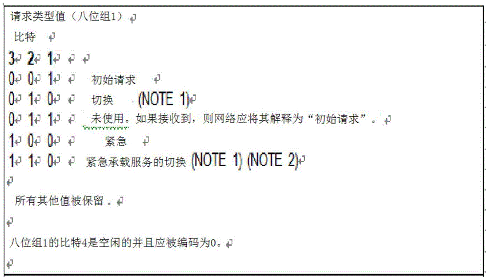
The request type value set to "010" in table 2 means that the PDN connection is sent to a 3GPP (or non-3 GPP) access in a non-3 GPP (or 3GPP) access. The transmission is not a 3GPP connection mode mobility procedure controlled handover as specified in 3GPP TS 25.331[23c ] and 3GPP TS 36.331[129 ]. The "handover of the emergency bearer service" is treated as "reserved bits" in the a/Gb mode and the Iu mode.
Referring to table 2, one unused value is reserved ("011"), and may be set/defined as indicating a request type for handover between 3GPP accesses, as shown in table 3, and used. At this time, handover between 3GPP accesses means handover from a 5G network.
[ Table 3]
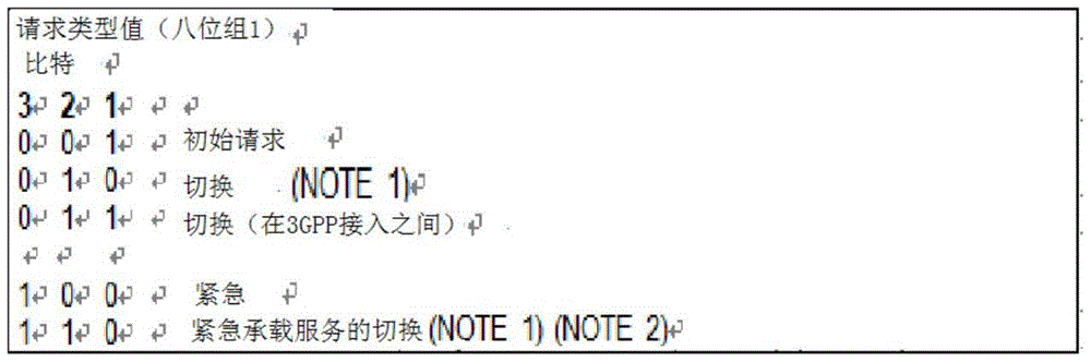
Additional request types may be newly defined and used if there is a need to distinguish between 3GPP and non-3 GPP accesses in a 5G network. For example, "011" may mean switching from 5G3GPP to EPC, and "101" may mean switching from 5G non-3 GPP to EPC.
Alternatively, there is a method of reusing existing handover request types and defining separate IEs, where PDU sessions are sent/delivered from PDU sessions to PDN connection request/PDU session request messages.
In a 5G network, multiple PDU sessions may be created using the same DNN (data network name). Therefore, the network cannot determine exactly which PDU session to send/receive by just knowing from which access to send/deliver the PDU session. For example, in a 5G network, two or more PDU sessions may be created using the same DNN via the E-URAN, in which case the MME should know exactly which PDU session to transfer/forward to the eNB to determine which SMF/P-GW to select. Accordingly, the UE can include a PDU session ID for identifying a PDU to be transmitted/delivered in a PDN connection request/PDU session request message, thereby being transmitted. At this time, the UE may include the PDU session ID in a newly defined IE in the PDN connection request/PDU session request message so as to be transmitted. In addition to transmitting the PDU session ID, the request type may be transmitted by the method set forth above.
If the PDU session ID is included in the PDN connection request transmitted from the UE, the MME selects an SMF/P-GW address matching the PDU session ID based on information received from the UDM + HSS, thereby processing the PDN connection request of the UE.
In the following, a solution to the following problem is proposed, relating to the case where the N26 interface is not present in the connected mode of the UE.
Additional optimization scheme allowing UE to skip TAU request/rejection when UE in connected mode moves from 5G to EPC
To minimize service interruption time when generating intersystem mobility in connected mode, the UE does not support dual registration and the network only supports interworking without the N26 interface.
Therefore, we propose to support RAN indication in order to skip unnecessary TAU failure of UE mobility from 5GC to EPC in connected mode. Two options are presented below.
Option 1: failure of handover preparation during handover preparation
Fig. 30 is a diagram illustrating a failed handover preparation operation according to an embodiment of the present invention.
Referring to fig. 30, the source NG-RAN may perform an inter-system handover (inter-RAT handover) by sending a handover request message to the AMF. In this case, the AMF may respond by sending a handover preparation failure message to the NG-RAN indicating that "inter-system handover is not supported". Thus, the source NG-RAN may perform the RRC release procedure while indicating that unnecessary TAU is skipped. If the UE receives an RRC Release message indicating "unnecessary TAU" from the E-UTRAN, the UE performs an access procedure with a handover indication (i.e., a handover attach/registration procedure).
Option 2: the AMF informs "inter-system handover is not supported" during the N2 setup procedure.
The NG-RAN is aware of the inter-system handover capability during the N2 setup procedure. When the NG-RAN detects UE mobility of the E-UTRAN, the NG-RAN can perform RRC release with "unnecessary TAUs" for an appropriate reason. Thus, the UE may perform a connection procedure using a PDN connection request message indicating "handover" to the EPC.
If the above options 1 and 2 are applied to the mobility part of 5.17.2.3.2 single registration mode UEs of TS 23.501, the result may be as follows.
5.17.2.3.2 mobility of a UE in Single registration mode
If the UE supports the single registration mode and the network supports interworking procedures without an N26 interface:
in case of moving from 5GC to EPC, the UE performs TAU procedure using 4G-GUTI mapped from 5G-GUTI. The MME determines that the old node is the AMF and rejects the TAU with an indication to the UE that handover PDN connection setup is supported. Based on this indication, the UE can perform the connection at the EPC with a "handover" indication in the PDN connection request message (TS23.401[26], section 5.3.2.1), and then the UE moves all other PDU sessions of the UE using the UE-initiated PDN connection establishment procedure (TS23.401[26], section 5.10.2). A first PDN connection may be established during an E-UTRAN initial access procedure (see TS23.401[26 ]).
In case of moving from EPC to 5GC, UE can perform "mobility registration update" type registration at 5GC with 5G-GUTI mapped from 4G-GUTI. The AMF determines that the old node is the MME, but proceeds as if the registration is of the "initial registration" type. The registration approval includes a "handover PDU session setup supported" indication for the UE. Based on this indication, the UE may continuously move all PDN connections from the EPC using a UE-initiated PDU session setup procedure with an "existing PDU session" flag (TS 23.502[3], section 4.3.2.2.1).
To minimize service interruption when the UE moves from 5GC to EPC in connected mode, the NG-RAN may provide assistance information to skip TAU procedure. If the UE AS receives support information for TAU procedure skipping, the UE NAS does not perform the TAU procedure but should perform the access procedure with the "handover" indication in the PDN connection request message in the EPC (TS23.401[26], section 5.3.2.1). The UE then moves all other PDU sessions of the UE using the UE-initiated PDN connection establishment procedure with the "handover" flag (TS23.401, section [5.6.2 ]).
In addition, a method for determining/indicating support information for skipping a TAU procedure in an RRC release message may be further defined.
Fig. 31 is a flowchart illustrating an interworking method between UEs in a network according to an embodiment of the present invention. The above-described embodiments can be applied to the flowcharts in the same manner, and redundant description will be omitted here.
The step of performing the first interworking procedure for changing the network of the UE from the 5GC network to the EPC network may be implemented in the following two embodiments according to whether an interface exists between the 5GC and EPC networks.
If there is no interface between the 5GC and the EPC network (e.g., N26):
the UE may receive a first indication from an AMF of the 5GC network (S3110). In this case, the first indication received by the UE may correspond to an explicit indication indicating that the UE performs handover attach or an implicit indication indicating that N26 is not present.
Next, the UE may perform a handover attach procedure in the EPC network based on the first indication (S3120). To this end, the UE may send a handover attach request message to the MME of the EPC network. In this case, the UE may send a PDN connectivity request message with the request type set to "handover" to the MME of the EPC.
If there is an interface between the 5GC and the EPC network (e.g., N26):
the UE may not receive the first indication from the AMF, and in this case, it may perform a TAU procedure in the EPC network.
All PDU sessions created in the 5GC for the UE can be transferred to the EPC network through a handover attach procedure or a TAU procedure. Specifically, through the TAU procedure, the MME may receive the PDU session of the UE directly from the AMF through an interface with the AMF.
Further, although not shown in the flowchart, the UE may transmit previous access information indicating that the UE moved from the 5GC to the MME while moving to the EPC.
In addition, the EPC to which the UE moves may have an EPC-GUTI mapped from 5GC GUTI.
If there is no interface between the 5GC and the EPC network and the UE is in 5GC connected mode, the UE may perform RRC release with the NGC RAN (or gNB) of the 5GC and camp in a cell connected with the EPC.
In addition, after the UE changes the network to the EPC, the UE may perform a second interworking procedure to change the network from the EPC network to a 5GC network. At this time, if there is no interface between the 5GC and the EPC network, a second indication may be received from the MME of the EPC network. The second indication at this time may also correspond to an explicit indication to perform a handover connection or an implicit indication that N26 is not present. Next, the UE may perform a registration procedure in the 5GC network based on the indication. The registration procedure at this time may correspond to a registration procedure in which the registration type is set to mobility registration update. All PDU sessions created for the UE in the EPC may be forwarded to the 5GC network through a registration procedure.
The UE may send previous access information to the AMF indicating movement from the EPC. The 5GC may have a 5GC-GUTI mapped from the GUTI of the EPC.
If there is no interface between the 5GC and the EPC network and the UE is in connected mode in the EPC, RRC release of E-UTRAN (e.g., eNBN) and EPC can be performed.
Apparatus to which the invention can be applied
Fig. 32 shows a block diagram of a communication device according to an embodiment of the invention.
Referring to fig. 32, the wireless communication system includes a network node 3210 and a plurality of ues (ues) 3220.
The network node 3210 includes a processor 3211, a memory 3212, and a communication module 3213. The processor 3211 implements the previously proposed functions, processes, and/or methods. Layers of the wired/wireless interface protocol may be implemented by the processor 3211. The memory 3212 is connected to the processor 3211 and stores various information for driving the processor 3211. The communication module 3213 is connected to the processor 3211 to transmit and/or receive wired/wireless signals. Some examples of the network node 3210 may include a base station, MME, HSS, SGW, PGW, and application server. In particular, when the network node 3210 is a base station, the communication module 3213 may include a radio frequency unit for transmitting/receiving radio signals.
The UE 3220 includes a processor 3221, a memory 3222, and a communication module (or RF section). The processor 3221 implements the previously proposed functions, procedures and/or methods. Layers of a radio interface protocol may be implemented by the processor 3221. The memory 3222 is connected to the processor 3221 and stores various information for driving the processor 3221. The communication module 3223 is coupled to the processor 3221 to transmit and/or receive wireless signals.
The memories 3212 and 3222 may be located inside or outside the processors 3211 and 3221 and may be coupled to the processors 3211 and 3221 by various well-known means. Further, the network node 3210 (in case of a base station) and/or the UE 3220 may have a single antenna or multiple antennas.
Fig. 33 shows a block diagram of a communication device according to an embodiment of the invention.
In particular, fig. 33 is a more detailed diagram of the UE of fig. 32.
Referring to fig. 33, the UE may include a processor (or Digital Signal Processor (DSP))3310, an RF module (or RF unit) 3335, a power management module 3305, an antenna 3340, a battery 3355, a display 3315, a keypad 3320, a memory 3330, a Subscriber Identity Module (SIM) card 3325 (which is optional), a speaker 3345, and a microphone 3350. The UE may also include a single antenna or multiple antennas.
The processor 3310 implements the functions, processes, and/or methods set forth above. Layers of the radio interface protocol may be implemented by the processor 3310.
The memory 3330 is connected to the processor 3310 and stores information related to the operation of the processor 3310. The memory 3330 may be located inside or outside the processor 3310 and may be connected to the processor 3310 by various means as is well known.
For example, the user inputs command information such as a phone number by pressing (or touching) a button of the keypad 3320 or by voice activation using the microphone 3350. The processor 3310 processes appropriate functions, such as receiving such command information or dialing a telephone number, in order to carry out the function. The operational data may be retrieved from the SIM card 3325 or the memory 3330. In addition, the processor 3310 may display command information or driving information on the display 3315 so that a user may recognize the information or for convenience.
The RF module 3335 is connected to the processor 3310 and transmits and/or receives RF signals. The processor 3310 communicates command information to the RF module 3335 to, for example, transmit radio signals forming voice communication data to initiate communication. The RF module 3335 includes a receiver and a transmitter to transmit and receive radio signals. The antenna 3340 is used for transmitting and receiving radio signals. When the RF module 3335 receives a radio signal, it transmits a signal for processing by the processor 3310 and may convert the signal into a baseband. The processed signals may be converted to audible or readable information by speaker 3345.
In the foregoing embodiments, elements and features of the present invention have been combined in specific forms. Each element or feature may be considered optional unless explicitly described otherwise. Each element or feature may be implemented without being combined with other elements or features. In addition, some elements and/or features may be combined to form embodiments of the invention. The order of operations described in the embodiments of the present invention may be changed. Some elements or features of an embodiment may be included in another embodiment or may be replaced with corresponding elements or features of another embodiment. It is obvious that an embodiment can be constructed by combining claims which are not explicitly cited in the claims, or can be included as a new claim by modification after filing the application.
Embodiments in accordance with the present invention may be implemented by various means, such as hardware, firmware, software, or a combination thereof. In the case of implementation by hardware, embodiments of the present invention may be implemented using one or more Application Specific Integrated Circuits (ASICs), Digital Signal Processors (DSPs), Digital Signal Processing Devices (DSPDs), Programmable Logic Devices (PLDs), Field Programmable Gate Arrays (FPGAs), processors, controllers, micro-controllers, microprocessors, or the like. .
In the case of implementation by firmware or software, the embodiments of the present invention may be implemented in the form of a module, a procedure, or a function for performing the above-described functions or operations. The software codes may be stored in a memory and driven by a processor. The memory may be located inside or outside the processor and may exchange data with the processor through various known means.
In the present specification, "a and/or B" may be interpreted to mean "at least one of a and (or) B".
It will be obvious to those having skill in the art that the present invention may be embodied in other specific forms without departing from the essential characteristics thereof. The detailed description is, therefore, not to be taken in a limiting sense, but is to be construed in an illustrative sense. The scope of the invention should be determined by reasonable analysis of the appended claims and all changes that come within the meaning and range of equivalency of the invention are intended to be embraced therein.
Industrial applicability
In the wireless communication system of the present invention, the method for reporting or supporting the number of UEs present in a geographical area has been described around the example applied to the 3GPP LTE/LTE-a/NR (5G) system, but may be applied to various wireless communication systems other than the 3GPP LTE/LTE-a/NR (5G) system.
Claims (15)
Applications Claiming Priority (9)
| Application Number | Priority Date | Filing Date | Title |
|---|---|---|---|
| US201762443838P | 2017-01-09 | 2017-01-09 | |
| US62/443,838 | 2017-01-09 | ||
| US201762444396P | 2017-01-10 | 2017-01-10 | |
| US62/444,396 | 2017-01-10 | ||
| US201762542807P | 2017-08-09 | 2017-08-09 | |
| US62/542,807 | 2017-08-09 | ||
| US201762583495P | 2017-11-09 | 2017-11-09 | |
| US62/583,495 | 2017-11-09 | ||
| PCT/KR2018/000440 WO2018128529A1 (en) | 2017-01-09 | 2018-01-09 | Method for interworking between networks in wireless communication system and apparatus therefor |
Publications (2)
| Publication Number | Publication Date |
|---|---|
| CN109155949A CN109155949A (en) | 2019-01-04 |
| CN109155949B true CN109155949B (en) | 2021-06-11 |
Family
ID=62789331
Family Applications (1)
| Application Number | Title | Priority Date | Filing Date |
|---|---|---|---|
| CN201880002078.3A Active CN109155949B (en) | 2017-01-09 | 2018-01-09 | Method and device for interworking between networks in wireless communication |
Country Status (7)
| Country | Link |
|---|---|
| US (2) | US10524166B2 (en) |
| EP (3) | EP3432641B1 (en) |
| JP (2) | JP6709341B2 (en) |
| KR (1) | KR102241996B1 (en) |
| CN (1) | CN109155949B (en) |
| ES (2) | ES2929669T3 (en) |
| WO (1) | WO2018128529A1 (en) |
Cited By (1)
| Publication number | Priority date | Publication date | Assignee | Title |
|---|---|---|---|---|
| US12022324B2 (en) | 2018-03-28 | 2024-06-25 | Zte Corporation | Methods and system for transmitting a temporary identifier |
Families Citing this family (234)
| Publication number | Priority date | Publication date | Assignee | Title |
|---|---|---|---|---|
| KR102449475B1 (en) * | 2016-10-21 | 2022-09-30 | 삼성전자 주식회사 | Network access method and apparatus of a terminal based on network information that the terminal can support in a wireless communication system |
| WO2018116423A1 (en) * | 2016-12-21 | 2018-06-28 | Panasonic Corporation | Communication apparatus and communication method |
| ES2798924T3 (en) | 2016-12-29 | 2020-12-14 | Ericsson Telefon Ab L M | Network node and method to configure PDCP for a wireless device |
| JP6908712B2 (en) * | 2017-01-11 | 2021-07-28 | テレフオンアクチーボラゲット エルエム エリクソン(パブル) | 5G QoS Flow vs. Wireless Bearer Remapping |
| US20180213540A1 (en) * | 2017-01-25 | 2018-07-26 | Acer Incorporated | Method of mapping data packets and related apparatuses using the same |
| US12075253B2 (en) * | 2017-01-26 | 2024-08-27 | Telefonaktiebolaget Lm Ericsson (Publ) | Attachment of a wireless device to a mobile network operator |
| EP3574665A1 (en) * | 2017-01-30 | 2019-12-04 | Telefonaktiebolaget LM Ericsson (Publ) | Wireless communications |
| BR112019015657B1 (en) * | 2017-02-01 | 2023-03-28 | Lg Electronics Inc | METHOD TO PERFORM REFLECTIVE QUALITY OF SERVICE (QOS) IN WIRELESS COMMUNICATION SYSTEM AND A DEVICE FOR THE SAME |
| US10772022B2 (en) * | 2017-02-10 | 2020-09-08 | Mediatek Inc. | Method and apparatus for inter-system handover in wireless communication |
| US10542454B2 (en) * | 2017-02-10 | 2020-01-21 | Mediatek Inc. | Control and management of reflective QoS |
| US10547374B1 (en) | 2017-02-13 | 2020-01-28 | Lockheed Martin Corporation | Random access for LTE over satellite |
| CN108632844B (en) * | 2017-03-15 | 2019-09-17 | 电信科学技术研究院 | Information processing method, device and electronic equipment |
| EP3598799B1 (en) | 2017-03-20 | 2022-06-08 | Huawei Technologies Co., Ltd. | Method, device, and system for moving between communication systems |
| CN108632915B (en) | 2017-03-20 | 2022-07-15 | 中兴通讯股份有限公司 | A method, device and device for terminal moving between 4G and 5G networks |
| US11122470B2 (en) * | 2017-05-04 | 2021-09-14 | Ofinno, Llc | Network slice information for handover procedure |
| EP3622681B1 (en) * | 2017-05-09 | 2023-08-16 | Telefonaktiebolaget LM Ericsson (publ) | Method and node for handling qos information |
| EP3632156B1 (en) * | 2017-06-02 | 2025-08-06 | Sharp Kabushiki Kaisha | Methods, devices, and systems for service-driven mobility management |
| CN110637477B (en) * | 2017-06-13 | 2022-05-13 | 苹果公司 | System, method and apparatus for legacy system fallback in a cellular communication system |
| KR102388936B1 (en) * | 2017-06-14 | 2022-04-22 | 삼성전자 주식회사 | Method and apparatus for registration to network and mobility support and data delivery |
| EP4075871B1 (en) * | 2017-06-19 | 2025-04-02 | InterDigital Patent Holdings, Inc. | User plane relocation |
| JP2019004406A (en) * | 2017-06-19 | 2019-01-10 | シャープ株式会社 | User apparatus, AMF, core network apparatus, P-CSCF, and communication control method |
| US11071021B2 (en) * | 2017-07-28 | 2021-07-20 | Qualcomm Incorporated | Security key derivation for handover |
| CN114339910A (en) | 2017-07-31 | 2022-04-12 | 华为技术有限公司 | Communication method, device and system |
| US11871291B2 (en) * | 2017-08-04 | 2024-01-09 | Apple Inc. | Data forwarding tunnel establishment between two user plane functions in fifth generation |
| EP4228304B1 (en) * | 2017-08-09 | 2025-05-14 | ZTE Corporation | Quality of service implementations for separating user plane |
| CN116367250A (en) | 2017-08-11 | 2023-06-30 | 北京三星通信技术研究有限公司 | Method and corresponding equipment supporting handover |
| CN109392043B (en) * | 2017-08-11 | 2023-04-14 | 北京三星通信技术研究有限公司 | Method and corresponding equipment supporting handover |
| US10764789B2 (en) * | 2017-08-11 | 2020-09-01 | Comcast Cable Communications, Llc | Application-initiated network slices in a wireless network |
| EP3534669B1 (en) * | 2017-08-14 | 2021-06-23 | HTC Corporation | Device and method of handling an interworking procedure |
| KR102329925B1 (en) | 2017-08-14 | 2021-11-23 | 삼성전자 주식회사 | A method and apparatus to support data synchronization for 4G/5G dual registered UE |
| US11082458B2 (en) * | 2017-08-18 | 2021-08-03 | T-Mobile Usa, Inc. | Web access in 5G environments |
| US11297502B2 (en) * | 2017-09-08 | 2022-04-05 | Futurewei Technologies, Inc. | Method and device for negotiating security and integrity algorithms |
| CN109673003B (en) * | 2017-10-17 | 2021-10-26 | 华为技术有限公司 | Switching method, mobility management network element and communication system |
| ES2926848T3 (en) | 2017-10-30 | 2022-10-28 | Huawei Tech Co Ltd | Methods, apparatus, system, and computer-readable storage media for obtaining security capabilities of user equipment |
| CN109803329B (en) * | 2017-11-16 | 2021-01-22 | 电信科学技术研究院 | Data forwarding tunnel determination method, access and mobility management equipment and base station |
| CN109819481B (en) * | 2017-11-20 | 2021-05-11 | 华为技术有限公司 | A kind of network switching method and session management network element |
| CN109819483B (en) * | 2017-11-21 | 2020-09-11 | 电信科学技术研究院 | Special bearer creation method, mobility management entity and packet data network gateway |
| CN109819486B (en) * | 2017-11-21 | 2022-04-08 | 中兴通讯股份有限公司 | Method and device for determining bearer identification, and storage medium |
| US10638374B2 (en) * | 2017-12-08 | 2020-04-28 | Futurewei Technologies, Inc. | Method and apparatus for reducing packet retransmission during handover (HO) in low latency mobile communication networks |
| CN109982383B (en) * | 2017-12-28 | 2020-10-09 | 华为技术有限公司 | Data sending method, device and equipment |
| WO2019134181A1 (en) | 2018-01-05 | 2019-07-11 | Oppo广东移动通信有限公司 | Method and device for radio communication |
| CN110022586B (en) * | 2018-01-08 | 2020-10-09 | 电信科学技术研究院 | Method and equipment for transmitting downlink data |
| KR20200108284A (en) * | 2018-01-11 | 2020-09-17 | 광동 오포 모바일 텔레커뮤니케이션즈 코포레이션 리미티드 | Service-based processing method, terminal device and network device |
| KR102492562B1 (en) * | 2018-01-12 | 2023-01-27 | 삼성전자주식회사 | Apparatus and method for security protection of network |
| CN110166984B (en) * | 2018-02-13 | 2021-09-24 | 维沃移动通信有限公司 | Business processing method, information sending method and related equipment |
| US11382175B2 (en) * | 2018-02-15 | 2022-07-05 | Telefonaktiebolaget Lm Ericsson (Publ) | Method for providing a breakout PDU session for local IP access |
| US10980084B2 (en) * | 2018-02-15 | 2021-04-13 | Huawei Technologies Co., Ltd. | Supporting multiple QOS flows for unstructured PDU sessions in wireless system using non-standardized application information |
| TWI714968B (en) * | 2018-02-22 | 2021-01-01 | 新加坡商 聯發科技(新加坡)私人有限公司 | Method of improved tracking area update procedure and apparatus thereof |
| US10419982B1 (en) | 2018-03-14 | 2019-09-17 | Cisco Technology, Inc. | Methods and apparatus for providing end marker functionality in mobile networks having SRv6-configured mobile user planes |
| WO2019192896A1 (en) * | 2018-04-04 | 2019-10-10 | Sony Corporation | Method and apparatus for management of extended mobile device identity information |
| US11323934B2 (en) * | 2018-04-09 | 2022-05-03 | Nokia Technologies Oy | Session context conversion |
| US20190313311A1 (en) * | 2018-04-09 | 2019-10-10 | Mediatek Inc. | Apparatuses, service networks, and methods for handling plmn-specific parameters for an inter-plmn handover |
| US11968614B2 (en) * | 2018-04-17 | 2024-04-23 | Mediatek Singapore Pte. Ltd. | Apparatuses and methods for handling access type restriction information |
| US10813044B2 (en) * | 2018-05-11 | 2020-10-20 | Apple Inc. | Access type selection in a 5G network |
| JP6954467B2 (en) | 2018-05-18 | 2021-10-27 | 日本電気株式会社 | Method, and AMF |
| US10484911B1 (en) | 2018-05-23 | 2019-11-19 | Verizon Patent And Licensing Inc. | Adaptable radio access network |
| CN110636567B (en) * | 2018-06-22 | 2022-11-22 | 中兴通讯股份有限公司 | Method, device and base station for evaluating and reporting switching |
| CN112586036B (en) | 2018-06-22 | 2024-11-08 | 诺基亚通信公司 | Selective switching or redirection based on interface availability |
| US10893560B2 (en) * | 2018-06-25 | 2021-01-12 | Verizon Patent And Licensing Inc. | Bearer control for secondary radio access technology in dual connectivity networks |
| WO2020000213A1 (en) * | 2018-06-26 | 2020-01-02 | 华为技术有限公司 | Data sending method, apparatus, and system |
| US10924518B2 (en) * | 2018-06-29 | 2021-02-16 | Cisco Technology, Inc. | UPF programming over enhanced N9 interface |
| WO2020030265A1 (en) * | 2018-08-08 | 2020-02-13 | Nokia Technologies Oy | Mapping logical network resources to transport resources |
| KR102201023B1 (en) | 2018-08-10 | 2021-01-11 | 텔레호낙티에볼라게트 엘엠 에릭슨(피유비엘) | Methods and nodes for facilitating PDU session procedure in interworking networks |
| CN110831033B (en) * | 2018-08-13 | 2021-08-20 | 华为技术有限公司 | Service quality monitoring method, equipment and system |
| CN110830994B (en) | 2018-08-13 | 2021-09-14 | 华为技术有限公司 | Session migration method, device and storage medium |
| US11539699B2 (en) | 2018-08-13 | 2022-12-27 | Lenovo (Singapore) Pte. Ltd. | Network slice authentication |
| WO2020036802A1 (en) * | 2018-08-13 | 2020-02-20 | Intel Corporation | Flexible scope of packet filters for reflective quality of service |
| EP3841833B1 (en) | 2018-08-21 | 2025-02-26 | Telefonaktiebolaget Lm Ericsson (Publ) | Technique for preparing user equipment mobility |
| US11115327B2 (en) * | 2018-08-24 | 2021-09-07 | Oracle International Corporation | Methods, systems, and computer readable media for providing mobile device connectivity |
| CN110881184B (en) | 2018-09-05 | 2021-05-18 | 华为技术有限公司 | Communication method and device |
| CN110944364B (en) * | 2018-09-25 | 2021-11-19 | 中国移动通信有限公司研究院 | Packet network information transmission method and network equipment |
| CN112703765B (en) * | 2018-09-27 | 2024-07-26 | 苹果公司 | Uplink in-sequence delivery for offloaded QoS flows in 5GC multi-RAT dual connectivity |
| EP3634041A1 (en) * | 2018-10-05 | 2020-04-08 | Ntt Docomo, Inc. | Communication terminal, method for requesting a connection, network component and method for serving a communication terminal |
| WO2020078417A1 (en) * | 2018-10-17 | 2020-04-23 | Mediatek Singapore Pte. Ltd. | Improved guti allocation after establishment of mobile-terminated connection in mobile communications |
| JP7196928B2 (en) * | 2018-10-18 | 2022-12-27 | 日本電気株式会社 | AMF, MME, AMF method and MME method |
| CN111147422B (en) * | 2018-11-02 | 2021-08-13 | 华为技术有限公司 | Method and device for controlling connection between terminal and network |
| EP3878201A4 (en) * | 2018-11-05 | 2022-08-03 | Parallel Wireless, Inc. | LOCALLY GENERATED TEID FOR HIGH HEART AVAILABILITY |
| WO2020034449A1 (en) * | 2018-11-06 | 2020-02-20 | Zte Corporation | Methods and systems for user equipment mobility management and registration |
| CN111200849B (en) * | 2018-11-19 | 2022-08-09 | 大唐移动通信设备有限公司 | User route updating method and device |
| US12295056B2 (en) | 2018-12-12 | 2025-05-06 | Comcast Cable Communications, Llc | Network assisted connection |
| CN109729387B (en) * | 2019-01-07 | 2021-05-14 | 烽火通信科技股份有限公司 | Playing method and system of live webcast after fault recovery based on HLS protocol |
| CN111436087B (en) * | 2019-01-15 | 2021-09-10 | 大唐移动通信设备有限公司 | PDU session switching method and device |
| CN113923647A (en) * | 2019-01-16 | 2022-01-11 | 华为技术有限公司 | Cell registration method and terminal equipment |
| CN111465011B (en) * | 2019-01-18 | 2021-07-16 | 华为技术有限公司 | Cross-network access method, device, storage medium and communication system |
| CN119519912A (en) * | 2019-01-24 | 2025-02-25 | 华为技术有限公司 | RA-RNTI processing method and device |
| CN111491340B (en) * | 2019-01-29 | 2021-11-02 | 大唐移动通信设备有限公司 | A communication system switching method, network side device, device and medium |
| CN113383563A (en) * | 2019-01-29 | 2021-09-10 | 苹果公司 | V2X UE with different PC5 RAT capabilities in 5GS |
| SG11202108249XA (en) * | 2019-02-01 | 2021-08-30 | Nokia Technologies Oy | Apparatus, methods, and computer programs for network slice selection |
| ES2993566T3 (en) | 2019-02-11 | 2025-01-02 | Nokia Technologies Oy | Enhanced mobility in cellular deployments with network slicing |
| EP3906751B1 (en) | 2019-02-12 | 2023-10-04 | Samsung Electronics Co., Ltd. | Managing bearer configuration of user equipment with en-dc capability |
| WO2020164023A1 (en) * | 2019-02-13 | 2020-08-20 | Oppo广东移动通信有限公司 | Radio resource management measurement method and system, terminal device and storage medium |
| US10925113B2 (en) | 2019-02-13 | 2021-02-16 | Telefonaktiebolaget Lm Ericsson (Publ) | Secondary authorization at PDU session establishment at home routed roaming |
| WO2020168253A1 (en) * | 2019-02-14 | 2020-08-20 | Apple Inc. | Downlink (dl) positioning reference signal (prs) bandwidth part (bwp) configuration reference signal design and user equipment (ue) based positioning enhancements for new radio (nr) positioning |
| PL3955698T3 (en) | 2019-02-14 | 2024-02-05 | Telefonaktiebolaget Lm Ericsson (Publ) | An enhanced up function requested pfcp association release |
| CN111565479B (en) * | 2019-02-14 | 2022-05-24 | 华为技术有限公司 | Communication method, device and system thereof |
| KR102636076B1 (en) * | 2019-02-15 | 2024-02-13 | 삼성전자주식회사 | Method and apparatus for processing non-access stratum protocol in wireless communication system |
| CN113273255A (en) * | 2019-02-15 | 2021-08-17 | Oppo广东移动通信有限公司 | Discontinuous reception method, terminal equipment and network equipment |
| EP3925191B1 (en) * | 2019-02-15 | 2024-12-25 | Telefonaktiebolaget Lm Ericsson (Publ) | A method of registering a service in a telecommunication network having a service based architecture, sba, as well as a corresponding collection controller |
| US11778522B2 (en) | 2019-02-18 | 2023-10-03 | Telefonaktiebolaget Lm Ericsson (Publ) | Methods and apparatuses for transferring restoration context data |
| MX2021009836A (en) * | 2019-02-18 | 2021-09-10 | Ericsson Telefon Ab L M | Methods and apparatuses for connection establishment. |
| US11134371B2 (en) | 2019-02-19 | 2021-09-28 | Huawei Technologies Co., Ltd. | Communication method and communications apparatus |
| CN111586774B (en) * | 2019-02-19 | 2021-06-29 | 华为技术有限公司 | Communication method and communication device |
| CN111629411B (en) | 2019-02-27 | 2021-08-20 | 华为技术有限公司 | A method for transferring between communication systems and related equipment |
| CN111726800A (en) * | 2019-03-04 | 2020-09-29 | 华为技术有限公司 | Method and apparatus for protecting auxiliary information |
| CN111770559B (en) * | 2019-03-12 | 2022-07-05 | Oppo广东移动通信有限公司 | Network connection method, terminal, base station, and computer storage medium |
| CN111726819B (en) * | 2019-03-19 | 2021-11-02 | 大唐移动通信设备有限公司 | Method and device for establishing and updating base station link |
| CN112005529B (en) * | 2019-03-27 | 2022-02-25 | Oppo广东移动通信有限公司 | Priority processing method, device and storage medium for QoS rules |
| JP7455138B2 (en) | 2019-03-28 | 2024-03-25 | ペキン シャオミ モバイル ソフトウェア カンパニー, リミテッド | Core paging processing |
| US12250579B2 (en) | 2019-03-28 | 2025-03-11 | Apple Inc. | Measuring the performance of a wireless communications network |
| US12114388B2 (en) * | 2019-03-28 | 2024-10-08 | Kyocera Corporation | Resume failure report for failed attempt to resume connected state from inactive state |
| EP3952373B1 (en) | 2019-03-28 | 2024-03-20 | Huawei Technologies Co., Ltd. | Cell selection method and device |
| CN111770124B (en) * | 2019-04-02 | 2022-01-11 | 华为技术有限公司 | Method and device for selecting session management network element |
| WO2020200297A1 (en) | 2019-04-02 | 2020-10-08 | 华为技术有限公司 | Method and apparatus for selecting session management network element |
| WO2020207401A1 (en) * | 2019-04-08 | 2020-10-15 | Mediatek Singapore Pte. Ltd. | 5g nas recovery from nasc failure |
| EP3959927B1 (en) * | 2019-04-26 | 2025-10-15 | Telefonaktiebolaget LM Ericsson (publ.) | Method, apparatus and computer program product for supporting interworking between core networks |
| KR20220002339A (en) | 2019-04-30 | 2022-01-06 | 광동 오포 모바일 텔레커뮤니케이션즈 코포레이션 리미티드 | User device and its wireless communication method |
| US11246064B2 (en) * | 2019-05-06 | 2022-02-08 | Mediatek Inc. | PDN connection supports interworking to 5GS |
| EP3737197B1 (en) | 2019-05-06 | 2022-12-07 | Comcast Cable Communications LLC | Wireless communications for asymmetric services |
| CN112019578B (en) * | 2019-05-29 | 2021-10-15 | 华为技术有限公司 | A method, device and system for establishing a user plane connection |
| CN114513789B (en) * | 2019-05-31 | 2023-09-01 | 荣耀终端有限公司 | Communication system and method for acquiring security context |
| US11252769B2 (en) * | 2019-06-14 | 2022-02-15 | Samsung Electronics Co., Ltd. | Method and apparatus for supporting various services in wireless communication system |
| CN110351804B (en) * | 2019-06-17 | 2021-11-12 | 腾讯科技(深圳)有限公司 | Communication method, communication device, computer readable medium and electronic equipment |
| EP3973723B1 (en) | 2019-06-17 | 2025-01-22 | Samsung Electronics Co., Ltd. | Method and apparatus for handling emergency services in a wireless communication system |
| CN112118606B (en) * | 2019-06-21 | 2022-04-29 | 华为技术有限公司 | Method, related device and system for realizing business continuity |
| CN112135306A (en) * | 2019-06-24 | 2020-12-25 | 中兴通讯股份有限公司 | Terminal movement management method, base station, network device, system and storage medium |
| CN112243279B (en) * | 2019-07-18 | 2022-03-29 | 华为技术有限公司 | Method, related device and system for realizing service continuity |
| US11452020B2 (en) * | 2019-07-22 | 2022-09-20 | Cisco Technology, Inc. | Maintaining internet protocol address for network traffic during handover procedure |
| JP7374294B2 (en) * | 2019-08-08 | 2023-11-06 | テレフオンアクチーボラゲット エルエム エリクソン(パブル) | Handling and equipment for 5GS interworking |
| US10841844B1 (en) | 2019-08-14 | 2020-11-17 | Dish Wireless L.L.C. | Anchor point movement in a compound cellular network |
| CN112399490B (en) * | 2019-08-15 | 2022-04-01 | 大唐移动通信设备有限公司 | Information processing method, device, equipment and computer readable storage medium |
| US11563676B2 (en) * | 2019-08-16 | 2023-01-24 | Nokia Technologies Oy | Method and apparatus for universal integrated circuit card update via dedicated network function |
| KR20210023614A (en) * | 2019-08-23 | 2021-03-04 | 삼성전자주식회사 | Network structure and service providing method for supporting multicast and broadcast service in mobile communication network |
| CN112449399B (en) | 2019-09-02 | 2023-03-10 | 华为技术有限公司 | A communication method, device and system |
| CN112469077B (en) * | 2019-09-09 | 2022-07-29 | 华为技术有限公司 | Method and device for forwarding service data packet |
| WO2021049841A1 (en) | 2019-09-09 | 2021-03-18 | 엘지전자 주식회사 | Method for moving ims voice session on non-3gpp to 3gpp access |
| CN112492681B (en) | 2019-09-12 | 2022-08-02 | 上海朗帛通信技术有限公司 | Method and apparatus in a node used for wireless communication |
| WO2021056162A1 (en) * | 2019-09-23 | 2021-04-01 | Oppo广东移动通信有限公司 | Method and apparatus for system interoperation |
| CN112584449B (en) * | 2019-09-30 | 2023-03-31 | 中国移动通信有限公司研究院 | Mobile session management method, device, equipment and storage medium |
| EP4329367B1 (en) * | 2019-10-02 | 2025-04-16 | LG Electronics Inc. | Method for moving pdu session on non-3gpp to 3gpp access |
| US12126994B2 (en) | 2019-10-04 | 2024-10-22 | Qualcomm Incorporated | User plane integrity protection (UP IP) capability signaling in 5G/4G systems |
| KR102307626B1 (en) * | 2019-10-23 | 2021-09-30 | 주식회사 엘지유플러스 | Method for time division duplex configuration and apparatus for managing session |
| CN112714407B (en) * | 2019-10-24 | 2024-05-28 | 中兴通讯股份有限公司 | Method, device and network management system for intercommunication between NSA network and SA network |
| KR102660607B1 (en) * | 2019-11-08 | 2024-04-25 | 삼성전자 주식회사 | Method and system for processing encoding of radio capability signaling information of a UE using RACS |
| TWI727501B (en) * | 2019-11-13 | 2021-05-11 | 財團法人資訊工業策進會 | Wireless communication core network and method for analyzing mobility of user equipment in the same |
| US11039359B1 (en) | 2019-11-19 | 2021-06-15 | Sprint Communications Company L.P. | Wireless communication device handovers between wireless communication network slices |
| EP4047985A4 (en) * | 2019-12-05 | 2022-11-09 | Huawei Technologies Co., Ltd. | Inter-network interoperation method, apparatus, and system |
| CN112954664B (en) * | 2019-12-10 | 2022-07-12 | 华为技术有限公司 | Data processing method, device and system |
| US10986489B1 (en) * | 2019-12-23 | 2021-04-20 | At&T Intellectual Property I, L.P. | Facilitation of machine type communication firmware over the air |
| WO2021138309A1 (en) * | 2019-12-31 | 2021-07-08 | Convida Wireless, Llc | Edge aware distributed network |
| CN113068239B (en) * | 2020-01-01 | 2022-05-24 | 华为技术有限公司 | Communication method and related device |
| US12389467B2 (en) * | 2020-02-06 | 2025-08-12 | Telefonaktiebolaget Lm Ericsson (Publ) | Tunnel initiation in a communications network |
| CN113271551B (en) | 2020-02-17 | 2022-07-05 | 大唐移动通信设备有限公司 | Data stream transmission method, terminal and network side equipment |
| US11356887B2 (en) * | 2020-02-24 | 2022-06-07 | Verizon Patent And Licensing Inc. | Systems and methods for selecting a core network slice for user plane communications |
| CN115136663B (en) * | 2020-02-26 | 2025-05-30 | 中兴通讯股份有限公司 | System and method for authorizing IAB node connection based on IAB node identification information |
| EP4115309A4 (en) * | 2020-03-03 | 2024-03-20 | The Trustees of Princeton University | TELEPHONE PRIVACY SYSTEM AND METHOD |
| WO2021098104A1 (en) * | 2020-03-20 | 2021-05-27 | Zte Corporation | Method of authorization for network slicing |
| CN113498132B (en) * | 2020-04-03 | 2022-09-20 | 维沃移动通信有限公司 | Mobility management method, source base station, target base station and terminal equipment |
| US11582609B2 (en) | 2020-05-21 | 2023-02-14 | T-Mobile Innovations Llc | Wireless user equipment (UE) authorization based on UE type and network identifier |
| US11343742B2 (en) | 2020-05-22 | 2022-05-24 | Blackberry Limited | Preserving emergency call during failure to transfer |
| CN113747421B (en) * | 2020-05-29 | 2022-08-30 | 中国电信股份有限公司 | Method, equipment and system for controlling terminal regression under mobile network sharing mechanism |
| WO2021243500A1 (en) | 2020-06-01 | 2021-12-09 | Zte Corporation | Network slice-specific aggregate maximum bit rate (ambr) configuration |
| WO2021243551A1 (en) * | 2020-06-02 | 2021-12-09 | Qualcomm Incorporated | Techniques for handover or redirection of ue from 4g to 5g (sa) |
| US12273481B2 (en) * | 2020-06-09 | 2025-04-08 | Telefonaktiebolaget Lm Ericsson (Publ) | Managing service interrupts in lawful interception |
| US11212699B1 (en) | 2020-06-24 | 2021-12-28 | Sprint Communications Company L.P. | Wireless guaranteed bit rate (GBR) data service |
| WO2022025558A1 (en) * | 2020-07-27 | 2022-02-03 | Lg Electronics Inc. | Method and apparatus for measurement in idle state or inactive state considering a network slice in a wireless communication system |
| CN114071596B (en) * | 2020-07-31 | 2025-05-06 | 维沃移动通信有限公司 | Session processing method, equipment and core network function during handover |
| US20230284108A1 (en) * | 2020-08-05 | 2023-09-07 | Telefonaktiebolaget Lm Ericsson (Publ) | Network nodes, and methods performed in a wireless communication network |
| US20230276220A1 (en) * | 2020-08-10 | 2023-08-31 | Telefonaktiebolaget Lm Ericsson (Publ) | Methods and Apparatuses for Mobility between Different Communication Systems |
| CN114079990B (en) * | 2020-08-12 | 2025-11-04 | 华为技术有限公司 | A communication method and apparatus |
| US11350319B2 (en) | 2020-08-24 | 2022-05-31 | Cisco Technology, Inc. | Optimized quality of service enforcement for handover between different radio access types |
| US11337056B1 (en) * | 2020-09-01 | 2022-05-17 | Sprint Communications Company L.P. | 5G network exposure function (NEF) capturing processor identity |
| US11399327B2 (en) * | 2020-09-24 | 2022-07-26 | Verizon Patent And Licensing Inc. | Systems and methods for fast return to 5G RAN after fallback to another RAN |
| WO2022069959A1 (en) * | 2020-10-02 | 2022-04-07 | Telefonaktiebolaget Lm Ericsson (Publ) | Establishing a secure connection |
| US11469912B2 (en) | 2020-10-05 | 2022-10-11 | Cisco Technology, Inc. | Secondary node status change indication to enable dynamic policy and quota management |
| US12133159B2 (en) | 2020-10-12 | 2024-10-29 | Cisco Technology, Inc. | In-band signaling of access network information along the user-plane for differentiated charging |
| KR102368830B1 (en) * | 2020-10-19 | 2022-02-28 | 주식회사 엘지유플러스 | Network interworking mehtod and device for performing the same |
| US11659468B2 (en) | 2020-10-22 | 2023-05-23 | Electronics And Telecommunications Research Institute | Method and apparatus for link configuration and routing of relay system |
| CN116349324A (en) * | 2020-10-23 | 2023-06-27 | 瑞典爱立信有限公司 | Method and apparatus for monitoring event configuration |
| CN114531692B (en) * | 2020-10-30 | 2025-06-13 | 华为技术有限公司 | A method and device for managing network slice data |
| US11470515B2 (en) | 2020-11-05 | 2022-10-11 | Cisco Technology, Inc. | Selection of same user plan function for user equipment movement across multiple access networks |
| US12089148B2 (en) | 2020-11-13 | 2024-09-10 | Samsung Electronics Co., Ltd. | Electronic device for searching a node based on identification information of cellular communication network and method for the same |
| WO2022120770A1 (en) * | 2020-12-10 | 2022-06-16 | 北京小米移动软件有限公司 | Monitoring determination method and device, and monitoring indication method and device |
| CN112911573B (en) * | 2020-12-28 | 2021-12-14 | 广州爱浦路网络技术有限公司 | Network element discovery method and NRF device for 4G/5G converged networking |
| US11523332B2 (en) * | 2020-12-29 | 2022-12-06 | Cisco Technology, Inc. | Cellular network onboarding through wireless local area network |
| KR20220096499A (en) * | 2020-12-31 | 2022-07-07 | 삼성전자주식회사 | Method and apparatus for supporting system interworiking in a wireless communication system |
| CN115396879B (en) * | 2021-01-10 | 2023-11-28 | 华为技术有限公司 | Security policy processing method, access device, security policy processing apparatus, and computer-readable storage medium |
| US11395111B1 (en) | 2021-01-28 | 2022-07-19 | Sprint Communications Company Lp | User charging over an exposure function in a wireless communication network |
| US11374983B1 (en) | 2021-01-29 | 2022-06-28 | Sprint Communications Company L.P. | Media content service delivery in a wireless communication network |
| US11451954B1 (en) | 2021-02-03 | 2022-09-20 | Sprint Communications Company L.P. | Wireless communication service delivery using multiple data network names (DNNs) |
| US20240235941A9 (en) * | 2021-02-17 | 2024-07-11 | Apple Inc. | Network Slice Quota Management Enhancements |
| US11751253B2 (en) | 2021-02-25 | 2023-09-05 | Lockheed Martin Corporation | Random access for broadband 4G and 5G over satellite |
| US11716283B2 (en) | 2021-03-05 | 2023-08-01 | Oracle International Corporation | Methods, systems, and computer readable media for selecting a software defined wide area network (SD-WAN) link using network slice information |
| US11576078B2 (en) | 2021-03-15 | 2023-02-07 | International Business Machines Corporation | Selective compression of data for uplink to a telecommunication network |
| JP7698961B2 (en) * | 2021-03-17 | 2025-06-26 | 株式会社国際電気通信基礎技術研究所 | COMMUNICATION PROCESSING METHOD, PROGRAM, COMMUNICATION SYSTEM, COMMUNICATION CONTROL DEVICE, AND AGGREGATION BASE STATION |
| US11540112B1 (en) | 2021-04-01 | 2022-12-27 | Sprint Communications Company Lp | Policy enforcement across wireless communication networks over application functions |
| CN120603053A (en) * | 2021-04-02 | 2025-09-05 | 华为技术有限公司 | Communication method, device and system |
| CN115175242B (en) * | 2021-04-06 | 2025-05-27 | 中国移动通信有限公司研究院 | A communication method, network device and computer readable storage medium |
| US11483750B1 (en) | 2021-04-07 | 2022-10-25 | Cisco Technology, Inc. | User equipment (UE) mobility between evolved packet system (EPS) and fifth generation (5G) system (5GS) using a simplified 3GPP core architecture for interworking |
| US11558920B2 (en) | 2021-04-14 | 2023-01-17 | T-Mobile Innovations Llc | Wireless user equipment (UE) control over wireless network slices based on slice requirements |
| US11490328B1 (en) | 2021-04-16 | 2022-11-01 | Sprint Communications Company Lp | Data communication system to serve a user equipment (UE) over a third generation partnership project (3GPP) network core |
| EP4292339A4 (en) | 2021-05-13 | 2024-07-10 | Samsung Electronics Co., Ltd. | METHOD AND SYSTEM FOR MANAGING CELL SELECTION IN A MOBILE NETWORK BASED ON EARLY MEASUREMENT CHARACTERISTICS |
| US11950218B2 (en) | 2021-05-14 | 2024-04-02 | Cisco Technology, Inc. | Auto-configuration of hybrid cells supporting shared cell and unique cell operating modes for user equipment in virtualized radio access network architectures |
| US12004025B2 (en) | 2021-05-14 | 2024-06-04 | Cisco Technology, Inc. | Supporting handovers in hybrid cell configuration environments |
| US11871271B2 (en) | 2021-05-17 | 2024-01-09 | Cisco Technology, Inc. | Dynamic switching for user equipment between unique cell and shared cell operating modes based on application traffic |
| US11882611B2 (en) | 2021-05-17 | 2024-01-23 | Cisco Technology, Inc. | Dual-connectivity support for user equipment in a hybrid cell virtualized radio access network architecture |
| US12382415B1 (en) | 2021-05-20 | 2025-08-05 | T-Mobile Innovations Llc | Network function registration with network repository functions |
| EP4096343A1 (en) * | 2021-05-28 | 2022-11-30 | Airbus SAS | Routing method and device implementing said method |
| US11778453B2 (en) | 2021-06-09 | 2023-10-03 | T-Mobile Innovations Llc | Radio access network (RAN) data exposure in a wireless communication network |
| US11757707B2 (en) | 2021-07-28 | 2023-09-12 | Cisco Technology, Inc. | Network assurance for 5G enterprise networks |
| US11902260B2 (en) * | 2021-08-02 | 2024-02-13 | Cisco Technology, Inc. | Securing control/user plane traffic |
| US11595247B1 (en) * | 2021-10-06 | 2023-02-28 | At&T Intellectual Property I, L.P. | Subscriber feedback mechanism for real-time network service upgrade |
| US12256274B2 (en) | 2021-10-10 | 2025-03-18 | Cisco Technology, Inc. | Evolved packet core to 5G core roaming using N9 interface |
| US11864099B2 (en) | 2021-10-22 | 2024-01-02 | T-Mobile Innovations Llc | Unified data repository (UDR) access across wireless communication networks |
| US12382379B2 (en) | 2021-11-29 | 2025-08-05 | T-Mobile Innovations Llc | Network exposure function (NEF) slice in a wireless communication network |
| US11985501B2 (en) | 2022-01-12 | 2024-05-14 | T-Mobile Innovations Llc | Third generation partnership project (3GPP) service delivery to non-3GPP user devices over 3GPP N1 links |
| CN116506837A (en) * | 2022-01-21 | 2023-07-28 | 上海华为技术有限公司 | A method and device for interoperability between systems |
| CN116567761B (en) * | 2022-01-30 | 2025-12-05 | 华为技术有限公司 | Communication methods and devices |
| JP2023127198A (en) * | 2022-03-01 | 2023-09-13 | 株式会社国際電気通信基礎技術研究所 | A terminal device, a wireless communication system equipped with the terminal device, and a program to be executed by a computer |
| US12520206B2 (en) * | 2022-05-24 | 2026-01-06 | Cisco Technology, Inc. | User equipment (UE) policy for selection of radio access technology (RAT) type for mobility from non-3GPP to 3GPP accesses |
| US12177929B2 (en) * | 2022-06-06 | 2024-12-24 | Cisco Technology, Inc. | Network-initiated group disconnect for wireless devices |
| EP4552432A1 (en) * | 2022-07-08 | 2025-05-14 | Lenovo (Beijing) Limited | Pdu set handling capability indication for xr traffic |
| CN121001112A (en) * | 2022-07-19 | 2025-11-21 | Oppo广东移动通信有限公司 | Methods, apparatus, equipment and storage media for determining the load configuration in the middle |
| GB2622353A (en) * | 2022-07-30 | 2024-03-20 | Samsung Electronics Co Ltd | Method and apparatus for energy performance policy |
| WO2024028736A1 (en) * | 2022-07-30 | 2024-02-08 | Jio Platforms Limited | System and method for provisioning interworking of communication networks with different radio access technologies |
| CN119698881A (en) * | 2022-08-10 | 2025-03-25 | 苹果公司 | Service restoration during registration to the NR network |
| US12520118B2 (en) | 2022-12-22 | 2026-01-06 | Hewlett Packard Enterprise Development Lp | 4G/5G session continuity management optimization |
| WO2024145946A1 (en) * | 2023-01-06 | 2024-07-11 | Nokia Shanghai Bell Co., Ltd. | Apparatus, method, and computer program |
| EP4668953A1 (en) * | 2023-02-15 | 2025-12-24 | Ntt Docomo, Inc. | Network node and communication method |
| CN116962343A (en) * | 2023-05-26 | 2023-10-27 | 海能达通信股份有限公司 | A message transmission method and system |
| WO2025062416A1 (en) * | 2023-09-18 | 2025-03-27 | Jio Platforms Limited | Method and system for handling a race condition |
| US12538188B2 (en) | 2023-09-26 | 2026-01-27 | T-Mobile Innovations Llc | Interworking between fifth generation core (5GC) and evolved packet core (EPC) in wireless communication networks |
| WO2025171550A1 (en) * | 2024-02-15 | 2025-08-21 | Nokia Shanghai Bell Co., Ltd. | Apparatus, method and computer program |
| US20250386313A1 (en) * | 2024-06-14 | 2025-12-18 | Interdigital Patent Holdings, Inc. | Methods and apparatus for enabling stateless communication in a mobile network |
| CN120224192B (en) * | 2025-05-26 | 2025-08-05 | 中国电子科技集团公司第三十研究所 | Mobile communication network safety monitoring method and device under non-cooperative condition |
Citations (3)
| Publication number | Priority date | Publication date | Assignee | Title |
|---|---|---|---|---|
| CN101577955A (en) * | 2008-07-11 | 2009-11-11 | 中兴通讯股份有限公司 | Method and system for determining activation of signaling-saving function in idle mode |
| CN103430580A (en) * | 2011-01-21 | 2013-12-04 | 黑莓有限公司 | Network means and process for determining a connection context for a connection used by (local) offloading |
| WO2016126238A1 (en) * | 2015-02-03 | 2016-08-11 | Nokia Solutions And Networks Oy | Improvements in dual connectivity for different access networks |
Family Cites Families (5)
| Publication number | Priority date | Publication date | Assignee | Title |
|---|---|---|---|---|
| US10897507B2 (en) * | 2016-04-01 | 2021-01-19 | Qualcomm Incorporated | Mechanism to enable connectivity sessions and IP session establishment |
| US10362511B2 (en) * | 2016-05-17 | 2019-07-23 | Lg Electronics Inc. | Method and apparatus for determining PDU session identity in wireless communication system |
| DE112017004452T5 (en) * | 2016-11-04 | 2019-06-19 | Intel Corporation | Internetworking between a next generation core and an evolved core package |
| WO2018085713A2 (en) * | 2016-11-04 | 2018-05-11 | Intel IP Corporation | Initial access and mode selection in evolved long term evolution (lte) networks |
| WO2018171918A1 (en) * | 2017-03-23 | 2018-09-27 | Telefonaktiebolaget Lm Ericsson (Publ) | Technique for inter-system handover |
-
2018
- 2018-01-09 EP EP18736726.3A patent/EP3432641B1/en active Active
- 2018-01-09 EP EP22192482.2A patent/EP4114065B1/en active Active
- 2018-01-09 WO PCT/KR2018/000440 patent/WO2018128529A1/en not_active Ceased
- 2018-01-09 ES ES18736726T patent/ES2929669T3/en active Active
- 2018-01-09 KR KR1020197002999A patent/KR102241996B1/en active Active
- 2018-01-09 CN CN201880002078.3A patent/CN109155949B/en active Active
- 2018-01-09 US US16/064,732 patent/US10524166B2/en active Active
- 2018-01-09 EP EP24174586.8A patent/EP4391715A3/en active Pending
- 2018-01-09 ES ES22192482T patent/ES2983234T3/en active Active
- 2018-01-09 JP JP2019529834A patent/JP6709341B2/en active Active
-
2019
- 2019-11-21 US US16/690,732 patent/US11184808B2/en active Active
-
2020
- 2020-05-21 JP JP2020089005A patent/JP6985455B2/en active Active
Patent Citations (3)
| Publication number | Priority date | Publication date | Assignee | Title |
|---|---|---|---|---|
| CN101577955A (en) * | 2008-07-11 | 2009-11-11 | 中兴通讯股份有限公司 | Method and system for determining activation of signaling-saving function in idle mode |
| CN103430580A (en) * | 2011-01-21 | 2013-12-04 | 黑莓有限公司 | Network means and process for determining a connection context for a connection used by (local) offloading |
| WO2016126238A1 (en) * | 2015-02-03 | 2016-08-11 | Nokia Solutions And Networks Oy | Improvements in dual connectivity for different access networks |
Non-Patent Citations (4)
| Title |
|---|
| 3GPP TR 23.799 V14.0.0 (2016-12);3GPP;《3GPP》;20161230;全文 * |
| Interworking between EPC and NGC;Intel Corporation;《3GPP TSG RAN WG3 Meeting #94,R3-162798》;20161118;全文 * |
| Interworking between LTE and 5G NR;CATT;《3GPP TSG RAN WG2 Meeting #93bis,R2-162566》;20160415;全文 * |
| Tight interworking between NR and LTE;NEC;《3GPP TSG RAN2#93bis,R2-162889》;20160415;全文 * |
Cited By (1)
| Publication number | Priority date | Publication date | Assignee | Title |
|---|---|---|---|---|
| US12022324B2 (en) | 2018-03-28 | 2024-06-25 | Zte Corporation | Methods and system for transmitting a temporary identifier |
Also Published As
| Publication number | Publication date |
|---|---|
| JP6985455B2 (en) | 2021-12-22 |
| EP3432641A4 (en) | 2019-10-09 |
| US20180376384A1 (en) | 2018-12-27 |
| JP2020123992A (en) | 2020-08-13 |
| EP4114065B1 (en) | 2024-06-12 |
| ES2929669T3 (en) | 2022-11-30 |
| US20200092758A1 (en) | 2020-03-19 |
| EP3432641A1 (en) | 2019-01-23 |
| US11184808B2 (en) | 2021-11-23 |
| CN109155949A (en) | 2019-01-04 |
| KR102241996B1 (en) | 2021-04-19 |
| KR20190020142A (en) | 2019-02-27 |
| ES2983234T3 (en) | 2024-10-22 |
| JP6709341B2 (en) | 2020-06-10 |
| EP4391715A3 (en) | 2024-08-07 |
| US10524166B2 (en) | 2019-12-31 |
| WO2018128529A1 (en) | 2018-07-12 |
| JP2019525690A (en) | 2019-09-05 |
| EP4391715A2 (en) | 2024-06-26 |
| EP3432641B1 (en) | 2022-10-05 |
| EP4114065A1 (en) | 2023-01-04 |
Similar Documents
| Publication | Publication Date | Title |
|---|---|---|
| CN109155949B (en) | Method and device for interworking between networks in wireless communication | |
| US11218904B2 (en) | Method for applying reflective quality of service in wireless communication system, and device therefor | |
| US11375471B2 (en) | Method for performing service request procedure and apparatus therefor in wireless communication system | |
| US11076376B2 (en) | De-registration method in wireless communication system and apparatus therefor | |
| US10917868B2 (en) | Method for notifying of mobility event in wireless communication system and device therefor | |
| CN109155909B (en) | Method for updating UE configuration in wireless communication system and apparatus thereof | |
| CN110431859B (en) | Method for interaction between layers in wireless communication system and apparatus therefor | |
| US10716083B2 (en) | Tracking area assignment method in wireless communication system and device therefor |
Legal Events
| Date | Code | Title | Description |
|---|---|---|---|
| PB01 | Publication | ||
| PB01 | Publication | ||
| SE01 | Entry into force of request for substantive examination | ||
| SE01 | Entry into force of request for substantive examination | ||
| GR01 | Patent grant | ||
| GR01 | Patent grant |