[go: up one dir, main page]

CN109152698B - Plasma bottle without sealing piece and top cover thereof - Google Patents

Plasma bottle without sealing piece and top cover thereof Download PDF

Info

Publication number
CN109152698B
CN109152698B CN201780030286.XA CN201780030286A CN109152698B CN 109152698 B CN109152698 B CN 109152698B CN 201780030286 A CN201780030286 A CN 201780030286A CN 109152698 B CN109152698 B CN 109152698B
Authority
CN
China
Prior art keywords
storage container
cap
plasma storage
container
plasma
Prior art date
Legal status (The legal status is an assumption and is not a legal conclusion. Google has not performed a legal analysis and makes no representation as to the accuracy of the status listed.)
Active
Application number
CN201780030286.XA
Other languages
Chinese (zh)
Other versions
CN109152698A (en
Inventor
C·S·麦克道尔
Current Assignee (The listed assignees may be inaccurate. Google has not performed a legal analysis and makes no representation or warranty as to the accuracy of the list.)
Haemonetics Corp
Original Assignee
Haemonetics Corp
Priority date (The priority date is an assumption and is not a legal conclusion. Google has not performed a legal analysis and makes no representation as to the accuracy of the date listed.)
Filing date
Publication date
Application filed by Haemonetics Corp filed Critical Haemonetics Corp
Publication of CN109152698A publication Critical patent/CN109152698A/en
Application granted granted Critical
Publication of CN109152698B publication Critical patent/CN109152698B/en
Active legal-status Critical Current
Anticipated expiration legal-status Critical

Links

Images

Classifications

    • AHUMAN NECESSITIES
    • A61MEDICAL OR VETERINARY SCIENCE; HYGIENE
    • A61JCONTAINERS SPECIALLY ADAPTED FOR MEDICAL OR PHARMACEUTICAL PURPOSES; DEVICES OR METHODS SPECIALLY ADAPTED FOR BRINGING PHARMACEUTICAL PRODUCTS INTO PARTICULAR PHYSICAL OR ADMINISTERING FORMS; DEVICES FOR ADMINISTERING FOOD OR MEDICINES ORALLY; BABY COMFORTERS; DEVICES FOR RECEIVING SPITTLE
    • A61J1/00Containers specially adapted for medical or pharmaceutical purposes
    • A61J1/14Details; Accessories therefor
    • A61J1/1406Septums, pierceable membranes
    • AHUMAN NECESSITIES
    • A61MEDICAL OR VETERINARY SCIENCE; HYGIENE
    • A61JCONTAINERS SPECIALLY ADAPTED FOR MEDICAL OR PHARMACEUTICAL PURPOSES; DEVICES OR METHODS SPECIALLY ADAPTED FOR BRINGING PHARMACEUTICAL PRODUCTS INTO PARTICULAR PHYSICAL OR ADMINISTERING FORMS; DEVICES FOR ADMINISTERING FOOD OR MEDICINES ORALLY; BABY COMFORTERS; DEVICES FOR RECEIVING SPITTLE
    • A61J1/00Containers specially adapted for medical or pharmaceutical purposes
    • A61J1/05Containers specially adapted for medical or pharmaceutical purposes for collecting, storing or administering blood, plasma or medical fluids ; Infusion or perfusion containers
    • AHUMAN NECESSITIES
    • A61MEDICAL OR VETERINARY SCIENCE; HYGIENE
    • A61JCONTAINERS SPECIALLY ADAPTED FOR MEDICAL OR PHARMACEUTICAL PURPOSES; DEVICES OR METHODS SPECIALLY ADAPTED FOR BRINGING PHARMACEUTICAL PRODUCTS INTO PARTICULAR PHYSICAL OR ADMINISTERING FORMS; DEVICES FOR ADMINISTERING FOOD OR MEDICINES ORALLY; BABY COMFORTERS; DEVICES FOR RECEIVING SPITTLE
    • A61J1/00Containers specially adapted for medical or pharmaceutical purposes
    • A61J1/03Containers specially adapted for medical or pharmaceutical purposes for pills or tablets
    • AHUMAN NECESSITIES
    • A61MEDICAL OR VETERINARY SCIENCE; HYGIENE
    • A61JCONTAINERS SPECIALLY ADAPTED FOR MEDICAL OR PHARMACEUTICAL PURPOSES; DEVICES OR METHODS SPECIALLY ADAPTED FOR BRINGING PHARMACEUTICAL PRODUCTS INTO PARTICULAR PHYSICAL OR ADMINISTERING FORMS; DEVICES FOR ADMINISTERING FOOD OR MEDICINES ORALLY; BABY COMFORTERS; DEVICES FOR RECEIVING SPITTLE
    • A61J1/00Containers specially adapted for medical or pharmaceutical purposes
    • A61J1/05Containers specially adapted for medical or pharmaceutical purposes for collecting, storing or administering blood, plasma or medical fluids ; Infusion or perfusion containers
    • A61J1/10Bag-type containers
    • A61J1/12Bag-type containers with means for holding samples of contents
    • AHUMAN NECESSITIES
    • A61MEDICAL OR VETERINARY SCIENCE; HYGIENE
    • A61JCONTAINERS SPECIALLY ADAPTED FOR MEDICAL OR PHARMACEUTICAL PURPOSES; DEVICES OR METHODS SPECIALLY ADAPTED FOR BRINGING PHARMACEUTICAL PRODUCTS INTO PARTICULAR PHYSICAL OR ADMINISTERING FORMS; DEVICES FOR ADMINISTERING FOOD OR MEDICINES ORALLY; BABY COMFORTERS; DEVICES FOR RECEIVING SPITTLE
    • A61J1/00Containers specially adapted for medical or pharmaceutical purposes
    • A61J1/14Details; Accessories therefor
    • A61J1/1412Containers with closing means, e.g. caps
    • A61J1/1431Permanent type, e.g. welded or glued
    • AHUMAN NECESSITIES
    • A61MEDICAL OR VETERINARY SCIENCE; HYGIENE
    • A61JCONTAINERS SPECIALLY ADAPTED FOR MEDICAL OR PHARMACEUTICAL PURPOSES; DEVICES OR METHODS SPECIALLY ADAPTED FOR BRINGING PHARMACEUTICAL PRODUCTS INTO PARTICULAR PHYSICAL OR ADMINISTERING FORMS; DEVICES FOR ADMINISTERING FOOD OR MEDICINES ORALLY; BABY COMFORTERS; DEVICES FOR RECEIVING SPITTLE
    • A61J1/00Containers specially adapted for medical or pharmaceutical purposes
    • A61J1/14Details; Accessories therefor
    • A61J1/20Arrangements for transferring or mixing fluids, e.g. from vial to syringe
    • A61J1/2003Accessories used in combination with means for transfer or mixing of fluids, e.g. for activating fluid flow, separating fluids, filtering fluid or venting
    • A61J1/2068Venting means
    • A61J1/2075Venting means for external venting
    • AHUMAN NECESSITIES
    • A61MEDICAL OR VETERINARY SCIENCE; HYGIENE
    • A61JCONTAINERS SPECIALLY ADAPTED FOR MEDICAL OR PHARMACEUTICAL PURPOSES; DEVICES OR METHODS SPECIALLY ADAPTED FOR BRINGING PHARMACEUTICAL PRODUCTS INTO PARTICULAR PHYSICAL OR ADMINISTERING FORMS; DEVICES FOR ADMINISTERING FOOD OR MEDICINES ORALLY; BABY COMFORTERS; DEVICES FOR RECEIVING SPITTLE
    • A61J1/00Containers specially adapted for medical or pharmaceutical purposes
    • A61J1/14Details; Accessories therefor
    • A61J1/20Arrangements for transferring or mixing fluids, e.g. from vial to syringe
    • A61J1/2003Accessories used in combination with means for transfer or mixing of fluids, e.g. for activating fluid flow, separating fluids, filtering fluid or venting
    • A61J1/2006Piercing means

Landscapes

  • Health & Medical Sciences (AREA)
  • Pharmacology & Pharmacy (AREA)
  • Life Sciences & Earth Sciences (AREA)
  • Animal Behavior & Ethology (AREA)
  • General Health & Medical Sciences (AREA)
  • Public Health (AREA)
  • Veterinary Medicine (AREA)
  • Hematology (AREA)
  • Physics & Mathematics (AREA)
  • Fluid Mechanics (AREA)
  • Medical Preparation Storing Or Oral Administration Devices (AREA)

Abstract

一种用于血浆储存容器的顶盖,包括顶盖主体,所述顶盖主体限定所述顶盖的结构并密封所述血浆储存容器的开口。所述顶盖还包括延伸穿过所述顶盖主体的第一开口和通气口。隔膜至少部分地位于所述第一开口内并包括穿过其中的孔。所述隔膜允许钝头套管穿过所述孔以进入所述血浆储存容器的内部。所述顶盖还包括位于所述顶盖主体的底侧的疏水膜。所述膜覆盖所述通气口并且在血浆采集期间允许空气通过所述通气口。

Figure 201780030286

A cap for a plasma storage container includes a cap body defining the structure of the cap and sealing the opening of the plasma storage container. The overcap also includes a first opening and a vent extending through the overcap body. A membrane is located at least partially within the first opening and includes a hole therethrough. The septum allows a blunt cannula to pass through the hole to access the interior of the plasma storage container. The cap also includes a hydrophobic membrane on the underside of the cap body. The membrane covers the vent and allows air to pass through the vent during plasma collection.

Figure 201780030286

Description

Plasma bottle without sealing piece and top cover thereof
Priority
The present patent application claims priority from U.S. provisional patent application No. 62/337,031, filed 2016, 5, 16, entitled "Plasma vial without seal and cap for Same", attorney docket No. 1611/C68, entitled "seal-Less Plasma vial and cap for Same", entitled "serum-Less Plasma vial and cap for Same", entitled "and filed" 2016 ", the disclosure of which is incorporated herein by reference in its entirety.
Technical Field
The present invention relates to blood component storage containers, and more particularly to plasma storage containers.
Background
Plasma is a yellowish liquid component of whole blood in which blood cells such as red and white blood cells, as well as other components of whole blood, are typically suspended. About 55% of the whole blood volume consists of plasma. Plasma plays an important role in the body's circulatory system, including transporting blood cells, conducting heat, and transporting waste products. Pure plasma contains coagulation factors that increase the rate at which blood clots, making it useful for surgery and the treatment of hemophilia. Stored whole blood is sometimes used to replace blood lost by a patient during surgery or due to trauma. However, if stored whole blood matching the patient's blood type is not available, plasma can sometimes be used to replace some of the lost blood. In addition, the plasma can be frozen and stored for relatively long periods of time until such time as the plasma is needed.
To collect plasma, whole blood may be collected from a donor, which may later be separated (e.g., in a laboratory) from the other components of the provided whole blood. In other cases, however, the plasma is separated from the other components of the whole blood at the providing location, and the other components are returned to the circulatory system of the donor. For example, apheresis is a medical technique in which the blood of a donor or patient is passed through a device, such as a centrifuge, which separates out a particular component and returns the remainder to the donor or patient. Plasmapheresis is a medical procedure that involves the separation of plasma from whole blood.
Collected plasma is typically stored in plastic bottles. A typical plasma bottle includes two ports, one for introducing plasma into the bottle and the other for venting air out of the bottle. Each port typically extends from a surface of the plasma bottle (e.g., the top cap of the plasma bottle) and may have a conduit connected thereto. After plasma is collected in the bottle, the catheter is severed using radio frequency sealing jaws, leaving a short (typically about 1-1/2 inches long) sealing spool attached to the port extending from the plasma bottle. These stubs often protrude from the neck of the bottle, which can cause problems during transport and storage. For example, when plasma freezes, the plastic of the nipple and/or port becomes brittle and may crack, violating the requirement to retain plasma in a sealed container.
Disclosure of Invention
In a first embodiment of the present invention, a cap for a plasma storage container is provided. The cap includes a cap body that defines the structure of the cap and seals the opening of the plasma storage container. The cap may also include a first opening extending through the cap body and a vent. The septum may be at least partially located within the first opening and may include a hole therethrough. The septum may allow passage of a blunt cannula through the aperture to access the interior of the plasma storage container. The cap may further include a hydrophobic membrane located on the bottom side of the cap body. The membrane covers the vent opening and can allow air to move through the vent opening during filling of the plasma storage container while preventing entry of unwanted microorganisms.
In some embodiments, the cap may further include a skirt extending downwardly from the bottom side of the cap body around the first opening. The septum may be located and secured (e.g., via a swaged (shock) connection) within the skirt. Alternatively, the diaphragm may be overmolded with the skirt. The skirt and/or the swaged connection may exert a compressive retention force on the bore. When the blunt cannula is not connected, the aperture may be closed and the first opening may be larger than the vent. Additionally or alternatively, the septum may allow the sample collection container holder to pass through the aperture to access the interior of the plasma collection container. For example, the sample collection container holder can be an evacuated blood collection tube holder. The blunt cannula may be part of a tubing set connected to a blood processing device.
The cap body may further include at least one flow channel located on a bottom side of the cap body. The at least one flow channel may be in fluid communication with the vent to allow gas flow into and out of the plasma storage container via the vent. The hydrophobic membrane may have a surface area greater than a cross-sectional area of the vent, and/or the hydrophobic membrane may be sealed and/or ultrasonically welded to the energy director on the underside of the cap body. The cap may include a retaining element (e.g., a clip) on a top surface of the cap body. The holder may hold the blunt cannula in place during filling of the plasma storage container.
According to further embodiments, a plasma storage container includes a container body defining a structure of the plasma storage container and defining an interior. The container includes a cap configured to seal an opening of the plasma storage container. The cap includes a first opening extending through the container cap and a vent. The septum may be at least partially located within the first opening and may include a pre-pierced hole therethrough. The septum/aperture allows the blunt cannula to pass through the aperture to access the interior of the plasma storage container. The container also includes a hydrophobic membrane located on the bottom side of the container top cover. The membrane covers the vent and allows air to pass through the vent during plasma collection. The first opening may be larger than the vent.
In some embodiments, the plasma storage container may include a skirt extending from a bottom side of the container top cap around the first opening. The diaphragm may be located and secured within the skirt, for example, by a swaged connection. Additionally or alternatively, the septum may be overmolded within the skirt. The skirt and/or the swaged connection may exert a radially inward force on the bore that biases the bore closed. The aperture may be closed when the blunt cannula is not connected.
The vessel header may include at least one flow channel located on a bottom side of the vessel header. The flow passage may be in fluid communication with the vent to allow gas flow into and out of the plasma storage container via the vent. The hydrophobic membrane may have a surface area greater than the cross-sectional area of the vent. Additionally or alternatively, the hydrophobic membrane may be ultrasonically welded to the bottom side of the container top and/or may be sealed to the bottom side of the container top.
In a further embodiment, the plasma storage container may include a retainer on a top surface of the container top cap. The retainer may hold the blunt cannula in place during filling of the plasma storage container, and/or the retainer may be a clip. In other embodiments, the septum may allow a sample collection container holder (e.g., an evacuated blood collection tube holder) to pass through the aperture to access the interior of the plasma collection container. The blunt cannula may be part of a tubing set connected to a blood processing device.
Drawings
The foregoing features of the embodiments will be more readily understood by reference to the following detailed description, taken with reference to the accompanying drawings, in which:
fig. 1 schematically shows a perspective view of a plasma storage container according to an embodiment of the invention.
Fig. 2 schematically illustrates a top perspective view of a top cover for the plasma storage container shown in fig. 1, wherein the top cover is not fitted with a septum and a hydrophobic membrane, according to an embodiment of the invention.
Fig. 3 schematically illustrates a bottom perspective view of a top cover for the plasma storage container shown in fig. 1, wherein the top cover is not fitted with a membrane and a hydrophobic membrane, according to an embodiment of the invention.
Fig. 4 schematically illustrates a top perspective view of a top cover for the plasma storage container shown in fig. 1 with a septum and hydrophobic membrane mounted thereto, in accordance with an embodiment of the present invention.
Fig. 5 schematically illustrates a bottom perspective view of a top cover for the plasma storage container shown in fig. 1 with a septum and hydrophobic membrane mounted thereto, in accordance with an embodiment of the present invention.
Fig. 6 schematically illustrates a top perspective view of a cap for the plasma storage container shown in fig. 1 with a blunt cannula inserted into the septum, according to an embodiment of the invention.
Fig. 7 schematically illustrates an exemplary blunt cannula for use with the plasma collection container of fig. 1, in accordance with an embodiment of the present invention.
Fig. 8 schematically illustrates an exemplary tube set including the blunt cannula of fig. 7, in accordance with an embodiment of the present invention.
FIG. 9 schematically illustrates an exemplary cap for the tube set of FIG. 8 with a blunt cannula inserted therein, in accordance with an embodiment of the present invention.
Detailed Description
Fig. 1 is a perspective view of a plasma container 100 according to an embodiment of the present invention. The plasma container 100 may have a body portion 110 and a cap 120 that closes an opening 130 (e.g., an open end in the body portion 110 at a proximal end 140 of the plasma container 100). As discussed in more detail below, plasma may be collected within the plasma container 100 and sampled through the cap 120. The body portion 110 defines an interior volume 150 (e.g., interior) in which collected plasma may be stored.
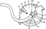
As shown in fig. 2 and 3, the top cover 120 includes a vent 160 through which air may pass bi-directionally during plasma collection 100 and an inlet aperture 170 through which plasma may be transferred into the plasma container 100. The size of the vent 160 and inlet aperture 170 may vary depending on the application, however, in some embodiments, the inlet aperture 170 may be much larger than the vent 160. Additionally, the top cover 120 may include a retainer 180 extending from the top surface 122 of the top cover. As discussed in more detail below, the retainer 180 may be used to secure a blunt cannula (which in turn is used to transfer plasma into the container 100) to the cap 120 of the plasma container 100 while plasma is being collected within the container 100. The retainer 180 may be any number of components capable of securing a blunt cannula. For example, retainer 180 may be a clip having two proximally extending projections 182A/B that define a space 184 therebetween in which a cannula may be positioned. In such an embodiment, the user may push the cannula into retainer/clip 180 until the cannula snaps/snaps into space 184. To hold the cannula in place within the clip 180, the protrusions 182A/B may include inward projections 183A/B that extend over the cannula when the cannula is positioned within the space 184.
On the bottom side 124, the top cap 120 may include a skirt 190 extending distally from the top cap 120 (e.g., downward from the top cap 120) and around the inlet opening 170. To help maintain the sterility of the container 100 and keep the inlet opening 170 closed when the container is not being filled with plasma (e.g., before and after filling), the cap 120 can include a septum 200 located and secured within the skirt 190. As best shown in fig. 4 and 5, the septum 200 may have a hole 210 extending through the body of the septum 200. The aperture 210 may be normally closed (e.g., closed when in its natural state and free of any external pressure), and/or the aperture 210 may be held closed by a radially compressive force applied to the septum 200 by the skirt 190. For example, septum 200 may be swaged into skirt 190. As is known in the art, when septum 200 is swaged within skirt 190, a portion of skirt 190 (e.g., the bottom of the skirt) may be compressed into septum 200. This creates a compressive force that retains septum 200 within skirt 190. Additionally or alternatively, the outer diameter of septum 200 may be greater than the inner diameter of skirt 190, and septum 200 may be press fit into skirt 190. This press fit will create a radially inward force that will hold the bore 210 closed.
It should be noted that although the apertures 210 are shown as slits in fig. 4 and 5, other aperture configurations may be used. For example, the hole 210 may be composed of two slits formed in a cross shape. Alternatively, the aperture 210 may have more than two slits in a star or star shape. It is important to note that the holes 210 (e.g., one or more slits) may be formed, for example, using conventional cutting devices (e.g., razor blades, knives, etc.), needle punched, or using ultrasonic cutting methods. Additionally or alternatively, the hole 210 may also be formed in the mold during or after the injection molding process.
Also on bottom side 124, top cover 120 may include a hydrophobic membrane 230 located below vent 160, such that hydrophobic membrane 230 may provide a sterile barrier for vent 160. During filling of the plasma container 100, the hydrophobic membrane 230 will allow air to pass through the membrane 230 and the vent 160 to prevent the build up of atmospheric pressure differences in the container 100. To facilitate air flow, the top cover may also include a plurality of channels 220 in the surface below hydrophobic membrane 230. For example, even if the membrane 230 is pushed against the bottom side 124 of the top cover 120 (e.g., during high air flow rates), the channels 220 may extend to the edges of the vents 160 and allow air to pass through the membrane 230.
Hydrophobic membrane 230 may be ultrasonically welded to top cover 120 (or otherwise sealed to top cover 120) to prevent air from leaking through hydrophobic membrane 230. To this end, the top cover 120 may include an energy director 222 for use during ultrasonic welding to ensure that the hydrophobic membrane 230 is properly sealed and secured to the bottom side 124 of the top cover 120. Alternatively, the membrane 230 may be secured to the top cover 120 by other attachment methods, including but not limited to adhesives, hot melts, and laser welds.
As shown in fig. 5, in order to maximize the surface area of hydrophobic membrane 230 and ensure that hydrophobic membrane 230 is able to handle the desired air flow into and out of container 100, hydrophobic membrane 230 may be sized such that it is much larger than vent/hole 160. In addition, to further maximize the use of membrane material, the hydrophobic membrane 230 may be square.
It should be noted that the cap 120 and the container body 110 may be formed as two separate pieces and then secured together by ultrasonic welding. To help facilitate ultrasonic welding, the cap 120 can include a distally extending wall 126 that extends over the top of the container body 110 when the cap 120 is placed over the body 110 (e.g., over the proximal end 140 of the body 110). Additionally, on the bottom side 124, the top cover 120 may include an energy director 128 to assist with the ultrasonic welding process (e.g., to secure the top cover 120 to the body 110).
During use and plasma collection, a user may connect the plasma container 100 to a blood processing device through the blunt cannula 240 (fig. 7) and the tubing set 300 (fig. 8), on which the blunt cannula 240 may be located. For example, a user may connect the blood processing device connector 310 at one end of the tube set 300 to a blood processing device (not shown) and connect the blunt cannula 240 at the other end of the tube set 300 to the plasma container 100. To connect the blunt cannula 240 to the plasma container 100, the user may insert the outlet portion 242 of the cannula 240 into the septum 200 and through the aperture 220. This will allow the cannula 240 to enter the interior volume 150 of the container 100 and create fluid communication between the interior volume 150 and the tubing set 300 (e.g., and the outlet of a blood processing device). The user may then snap the body 244 of the cannula 240 into the retainer 180 to hold the cannula 240 in place on the cap 120 (fig. 6).
When the blood processing device separates plasma from whole blood and delivers the plasma to the storage container 100, the plasma may flow through the tubing set 300 and into the interior volume 150 of the container 100 via the blunt cannula 240. As plasma flows into the container 100, air will exit the container 100 through the hydrophobic membrane 230 and the vent/port 160. This in turn will prevent pressure from building up within the container 100. Air may also enter the container 100 through the hydrophobic/antiseptic membrane 230 and the vent/port 160 as needed/desired by the blood processing device. This in turn will prevent vacuum build-up within the container 100.
To facilitate storage and to ensure that the opening in the outlet portion 242 of the cannula 240 is covered and not exposed to the atmosphere, the tubing set 300 may include a cap 320 that can be used for both the blood processing set connector 310 and the outlet portion 242 of the cannula 240. For example, the cap 320 may have an open end 322 that may be placed over the blood processing set connector 310 when not in use. Additionally, the top 324 of the cap 320 may have an opening 326 into which the outlet portion 242 of the cannula 240 may be inserted. In some embodiments, the cap 320 may be tethered to the blood component set connector 310.
Once plasma is collected within the container 100, it may be desirable to sample the collected plasma at various times (e.g., after collection, at some point during storage, before use). To do so, the user may insert a sample collection container holder (e.g., an evacuated blood collection tube holder) into the septum 200/well 210 to access the volume of plasma within the container 100. The user may then invert the container 100 and connect the evacuated blood collection tube to the holder to begin collecting the plasma sample within the evacuated blood collection tube. It should be noted that collecting the plasma sample in this manner may provide as much of the plasma sample as possible in the container 100, and minimize/eliminate any plasma loss that may otherwise be present in a sampling device involving sampling through a conduit external to the cap 120.
Although the above-described embodiments eliminate the port for introducing plasma into the prior art container and the port for venting the prior art container (e.g., the port extending from the plasma container and the tubing segment connected to the port, as described above), some embodiments may eliminate only a single port (e.g., the container may retain one port). For example, some embodiments may use the inlet port 170 and septum 200 but retain a vent port (e.g., a vent port extending from the plasma container and having a tubing segment connected thereto). Alternatively, some embodiments may use the vent 160 and hydrophobic membrane 230 but leave a port for introducing plasma into the bottle (e.g., an inlet port extending from the plasma container and having a tube segment extending therefrom).
It should be noted that the various embodiments of the present invention provide a number of advantages over prior art plasma storage containers. For example, because embodiments of the present invention eliminate one or more of the plastic stubs and ports mentioned above, some embodiments of the present invention can reduce and/or eliminate the risk of breaching and compromising the sterility of the product. In addition, various embodiments of the present invention can eliminate the need for thermal/RF sealing equipment and processes for sealing conduits prior to shipping and storage. In addition, because embodiments of the present invention allow for the collection of samples directly through the septum 200 (e.g., as opposed to first drawing plasma into the tubing segment as in many prior art systems), the present invention enables the collection of highly representative plasma samples with little/no loss.
The above-described embodiments of the present invention are intended to be illustrative only; many variations and modifications will be apparent to those of ordinary skill in the art. All such variations and modifications are intended to be within the scope of the present invention as defined in any appended claims.

Claims (31)

1.一种用于血浆储存容器的顶盖,包括:1. A cap for a plasma storage container, comprising: 顶盖主体,所述顶盖主体限定所述顶盖的结构并构造成密封所述血浆储存容器的开口;a cap body defining the structure of the cap and configured to seal the opening of the plasma storage container; 延伸穿过所述顶盖主体的第一开口;extending through a first opening of the cap body; 至少部分地位于所述第一开口内的隔膜,所述隔膜包括穿过其中的孔并构造成允许钝头套管穿过所述孔以进入所述血浆储存容器的内部;a septum located at least partially within the first opening, the septum including a bore therethrough and configured to allow a blunt cannula to pass through the bore to access the interior of the plasma storage container; 延伸穿过所述顶盖主体的通气口;和a vent extending through the cap body; and 疏水膜,所述疏水膜位于所述顶盖主体的底侧并覆盖所述通气口,所述疏水膜构造成在填充所述血浆储存容器期间允许空气通过所述通气口。a hydrophobic membrane on the underside of the cap body and covering the vent, the hydrophobic membrane configured to allow air to pass through the vent during filling of the plasma storage container. 2.根据权利要求1所述的用于血浆储存容器的顶盖,还包括:2. The cap for a plasma storage container according to claim 1, further comprising: 从所述顶盖主体的底侧围绕所述第一开口延伸的裙部,所述隔膜位于并固定在所述裙部内。A skirt extending from the bottom side of the cap body around the first opening in which the diaphragm is located and secured. 3.根据权利要求2所述的用于血浆储存容器的顶盖,其中,所述隔膜通过型锻连接固定在所述裙部内。3. The cap for a plasma storage container of claim 2, wherein the septum is secured within the skirt by a swaged connection. 4.根据权利要求3所述的用于血浆储存容器的顶盖,其中,所述裙部和/或所述型锻连接在所述隔膜上施加径向向内的力,所述径向向内的力保持所述隔膜固定在所述裙部内。4. A cap for a plasma storage container according to claim 3, wherein the skirt and/or the swaged connection exerts a radially inward force on the septum, the radially Internal forces keep the diaphragm secured within the skirt. 5.根据权利要求1所述的用于血浆储存容器的顶盖,其中,当所述钝头套管未连接时,所述孔关闭。5. The cap for a plasma storage container of claim 1, wherein the aperture is closed when the blunt cannula is not connected. 6.根据权利要求1所述的用于血浆储存容器的顶盖,其中,所述第一开口大于所述通气口。6. The cap for a plasma storage container of claim 1, wherein the first opening is larger than the vent. 7.根据权利要求1所述的用于血浆储存容器的顶盖,其中,所述顶盖主体包括位于所述顶盖主体的底侧的至少一个流动通道,所述至少一个流动通道与所述通气口流体连通,以允许气流经由所述通气口进出所述血浆储存容器。7. The cap for a plasma storage container of claim 1, wherein the cap body includes at least one flow channel on a bottom side of the cap body, the at least one flow channel being connected to the A vent is in fluid communication to allow airflow into and out of the plasma storage container via the vent. 8.根据权利要求1所述的用于血浆储存容器的顶盖,其中,所述疏水膜的表面积大于所述通气口的横截面面积。8. The cap for a plasma storage container of claim 1, wherein the surface area of the hydrophobic membrane is greater than the cross-sectional area of the vent. 9.根据权利要求1所述的用于血浆储存容器的顶盖,其中,所述疏水膜被超声波焊接到所述顶盖主体的底侧。9. The cap for a plasma storage container of claim 1, wherein the hydrophobic membrane is ultrasonically welded to the bottom side of the cap body. 10.根据权利要求1所述的用于血浆储存容器的顶盖,其中,所述疏水膜被密封到所述顶盖主体的底侧。10. The cap for a plasma storage container of claim 1, wherein the hydrophobic membrane is sealed to the bottom side of the cap body. 11.根据权利要求1所述的用于血浆储存容器的顶盖,还包括:11. The cap for a plasma storage container of claim 1, further comprising: 位于所述顶盖主体的顶表面上的保持器,所述保持器构造成在填充所述血浆储存容器期间将所述钝头套管保持就位。A retainer on a top surface of the cap body configured to hold the blunt cannula in place during filling of the plasma storage container. 12.根据权利要求11所述的用于血浆储存容器的顶盖,其中,所述保持器是夹子。12. The cap for a plasma storage container of claim 11, wherein the retainer is a clip. 13.根据权利要求1所述的用于血浆储存容器的顶盖,其中,所述隔膜进一步构造成允许样品采集容器保持器穿过所述孔以进入所述血浆存储 容器的内部。13. The cap for a plasma storage container of claim 1, wherein the septum is further configured to allow a sample collection container holder to pass through the aperture to access the interior of the plasma storage container. 14.根据权利要求13所述的用于血浆储存容器的顶盖,其中,所述样品采集容器保持器是真空采血管保持器。14. The cap for a plasma storage container of claim 13, wherein the sample collection container holder is a vacuum blood collection tube holder. 15.根据权利要求1所述的用于血浆储存容器的顶盖,其中,所述钝头套管是连接到血液处理装置的管组的一部分。15. The cap for a plasma storage container of claim 1, wherein the blunt cannula is part of a tubing set connected to a blood processing device. 16.一种血浆储存容器,包括:16. A plasma storage container comprising: 容器主体,所述容器主体限定所述血浆储存容器的结构并限定内部;a container body defining the structure of the plasma storage container and defining an interior; 容器顶盖,所述容器顶盖构造成密封所述血浆储存容器的开口;a container cap configured to seal the opening of the plasma storage container; 延伸穿过所述容器顶盖的第一开口;extending through a first opening of the container lid; 至少部分地位于所述第一开口内的隔膜,所述隔膜包括穿过其中的孔并构造成允许钝头套管穿过所述孔以进入所述血浆储存容器的内部;a septum located at least partially within the first opening, the septum including a bore therethrough and configured to allow a blunt cannula to pass through the bore to access the interior of the plasma storage container; 延伸穿过所述容器顶盖的通气口;和a vent extending through the lid of the container; and 疏水膜,所述疏水膜位于所述容器顶盖的底侧并覆盖所述通气口,所述疏水膜构造成在血浆采集期间允许空气通过所述通气口。a hydrophobic membrane located on the underside of the container cap and covering the vent, the hydrophobic membrane configured to allow air to pass through the vent during plasma collection. 17.根据权利要求16所述的血浆储存容器,还包括:17. The plasma storage container of claim 16, further comprising: 从所述容器顶盖的底侧围绕所述第一开口延伸的裙部,所述隔膜位于并固定在所述裙部内。A skirt extending from the bottom side of the container cap around the first opening in which the membrane is located and secured. 18.根据权利要求17所述的血浆储存容器,其中,所述隔膜通过型锻连接固定在所述裙部内。18. The plasma storage container of claim 17, wherein the septum is secured within the skirt by a swaged connection. 19.根据权利要求18所述的血浆储存容器,其中,所述裙部和/或所述型锻连接在所述孔上施加径向向内的力,所述径向向内的力偏压所述孔使其关闭。19. The plasma storage container of claim 18, wherein the skirt and/or the swaged connection exerts a radially inward force on the bore, the radially inward force biasing The hole closes it. 20.根据权利要求17所述的血浆储存容器,其中,所述隔膜被包覆成型在所述裙部内。20. The plasma storage container of claim 17, wherein the septum is overmolded within the skirt. 21.根据权利要求16所述的血浆储存容器,其中,当所述钝头套管未连接时,所述孔关闭。21. The plasma storage container of claim 16, wherein the aperture is closed when the blunt cannula is not connected. 22.根据权利要求16所述的血浆储存容器,其中,所述第一开口大于所述通气口。22. The plasma storage container of claim 16, wherein the first opening is larger than the vent. 23.根据权利要求16所述的血浆储存容器,其中,所述容器顶盖包括位于所述容器顶盖的底侧的至少一个流动通道,所述至少一个流动通道与所述通气口流体连通,以允许气流经由所述通气口进出所述血浆储存容器。23. The plasma storage container of claim 16, wherein the container cap includes at least one flow channel on an underside of the container cap, the at least one flow channel being in fluid communication with the vent, to allow airflow into and out of the plasma storage container through the vent. 24.根据权利要求23所述的血浆储存容器,其中,所述疏水膜的表面积大于所述通气口的横截面面积。24. The plasma storage container of claim 23, wherein the surface area of the hydrophobic membrane is greater than the cross-sectional area of the vent. 25.根据权利要求16所述的血浆储存容器,其中,所述疏水膜被超声波焊接到所述容器顶盖的底侧。25. The plasma storage container of claim 16, wherein the hydrophobic membrane is ultrasonically welded to the bottom side of the container top lid. 26.根据权利要求16所述的血浆储存容器,其中,所述疏水膜被密封到所述容器顶盖的底侧。26. The plasma storage container of claim 16, wherein the hydrophobic membrane is sealed to the bottom side of the container top lid. 27.根据权利要求16所述的血浆储存容器,还包括:27. The plasma storage container of claim 16, further comprising: 位于所述容器顶盖的顶表面上的保持器,所述保持器构造成在填充所述血浆储存容器期间将所述钝头套管保持就位。A retainer on a top surface of the container cap, the retainer configured to hold the blunt cannula in place during filling of the plasma storage container. 28.根据权利要求27所述的血浆储存容器,其中,所述保持器是夹子。28. The plasma storage container of claim 27, wherein the retainer is a clip. 29.根据权利要求16所述的血浆储存容器,其中,所述隔膜进一步构造成允许样品采集容器保持器穿过所述孔以进入所述血浆存储 容器的内部。29. The plasma storage container of claim 16, wherein the septum is further configured to allow a sample collection container holder to pass through the aperture to access the interior of the plasma storage container. 30.根据权利要求29所述的血浆储存容器,其中,所述样品采集容器保持器是真空采血管保持器。30. The plasma storage container of claim 29, wherein the sample collection container holder is a vacuum blood collection tube holder. 31.根据权利要求16所述的血浆储存容器,其中,所述钝头套管是连接到血液处理装置的管组的一部分。31. The plasma storage container of claim 16, wherein the blunt cannula is part of a tubing set connected to a blood processing device.
CN201780030286.XA 2016-05-16 2017-05-16 Plasma bottle without sealing piece and top cover thereof Active CN109152698B (en)

Applications Claiming Priority (3)

Application Number Priority Date Filing Date Title
US201662337031P 2016-05-16 2016-05-16
US62/337,031 2016-05-16
PCT/US2017/032824 WO2017200992A1 (en) 2016-05-16 2017-05-16 Sealer-less plasma bottle and top for same

Publications (2)

Publication Number Publication Date
CN109152698A CN109152698A (en) 2019-01-04
CN109152698B true CN109152698B (en) 2022-07-01

Family

ID=60326384

Family Applications (1)

Application Number Title Priority Date Filing Date
CN201780030286.XA Active CN109152698B (en) 2016-05-16 2017-05-16 Plasma bottle without sealing piece and top cover thereof

Country Status (5)

Country Link
US (1) US11559464B2 (en)
EP (1) EP3461259B1 (en)
CN (1) CN109152698B (en)
HU (1) HUE054412T2 (en)
WO (1) WO2017200992A1 (en)

Families Citing this family (5)

* Cited by examiner, † Cited by third party
Publication number Priority date Publication date Assignee Title
CN109152698B (en) 2016-05-16 2022-07-01 美国血液技术公司 Plasma bottle without sealing piece and top cover thereof
US11648179B2 (en) 2016-05-16 2023-05-16 Haemonetics Corporation Sealer-less plasma bottle and top for same
AU2019272750B2 (en) * 2018-05-22 2024-10-10 Haemonetics Corporation Sealer-less plasma bottle and top for same
US11344480B2 (en) * 2018-07-26 2022-05-31 Medline Industries, Lp Enteral fluid delivery system
CN108784927B (en) * 2018-08-29 2024-02-27 无锡市第二人民医院 Ophthalmic medicine dropping bottle

Family Cites Families (88)

* Cited by examiner, † Cited by third party
Publication number Priority date Publication date Assignee Title
US2447691A (en) 1947-02-17 1948-08-24 Baxter Don Inc Device for packaging and dispensing intravenous solutions
US3952902A (en) 1974-04-26 1976-04-27 Cutter Laboratories, Inc. Closure cap for plasma receiving assembly
NL7707814A (en) 1976-08-03 1978-02-07 Abbott Lab PLASTIC HOLDERS.
US4508236A (en) 1982-09-13 1985-04-02 Baxter Travenol Laboratories, Inc. Container and associated cap assembly for plasma collection and the like
US4568345A (en) 1982-09-13 1986-02-04 Baxter Travenol Laboratories, Inc. Container and associated cap assembly for plasma collection and the like
US4744785A (en) 1984-10-02 1988-05-17 C. R. Bard, Inc. Autotransfusion system
US5045077A (en) * 1985-11-25 1991-09-03 Blake Joseph W Iii Body cavity drainage implement
US5964785A (en) * 1988-01-25 1999-10-12 Baxter International Inc. Bayonet look cannula for pre-slit y-site
US4934545A (en) 1989-01-19 1990-06-19 Abbott Laboratories Closure with microbial filter
IE66526B1 (en) 1989-03-17 1996-01-24 Baxter Int A pre-slit injection site usable with a blunt cannula
JP2803170B2 (en) 1989-06-07 1998-09-24 日本電気株式会社 Semiconductor wafer transfer equipment
US5132026A (en) 1991-03-21 1992-07-21 Alpha Therapeutic Corporation Blood plasma collection system
JPH0577039A (en) 1991-09-20 1993-03-30 Nippon Light Metal Co Ltd Manufacture of header pipe for heat exchanger
DE4317316C2 (en) 1993-05-25 1995-04-27 Fresenius Ag Bag arrangements for enteral nutrition
US7033339B1 (en) 1998-05-29 2006-04-25 Becton Dickinson And Company (Part Interest) Self sealing luer receiving stopcock
CN2199152Y (en) 1994-06-21 1995-05-31 余润民 Rotary beverage bottle with separated solid and liquid
CA2185494A1 (en) 1995-09-27 1997-03-28 Jean-Pierre Grimard Resealable vial with connector assembly having a membrane and pusher
US6391014B1 (en) 1996-12-20 2002-05-21 David G. Silverman Strong diaphragm/safe needle/converting device combinations and their individual components
DE19723197C2 (en) * 1997-06-03 1999-07-29 Braun Melsungen Ag Suction device for body fluids
AU9202398A (en) 1997-09-29 1999-04-23 Becton Dickinson & Company Injection device and drug cartridge for preventing cross-use of the device and drug cartridge
IT236233Y1 (en) 1997-11-26 2000-08-08 Eurospital S P A DEVICE FOR THE CONNECTION OF A PHARMACEUTICAL PRODUCT CONTAINER TO A BAG OF LIQUID PRODUCT TO CARRY OUT THE
US6090092A (en) 1997-12-04 2000-07-18 Baxter International Inc. Sliding reconstitution device with seal
US6012596A (en) * 1998-03-19 2000-01-11 Abbott Laboratories Adaptor cap
US6209738B1 (en) 1998-04-20 2001-04-03 Becton, Dickinson And Company Transfer set for vials and medical containers
US6426049B1 (en) 1999-07-09 2002-07-30 Becton, Dickinson And Company Collection assembly
US6171261B1 (en) 1999-08-06 2001-01-09 Becton Dickinson And Company Specimen collection device and method of delivering fluid specimens to test tubes
US6475194B2 (en) 2000-04-05 2002-11-05 Gem Plastics, Inc. Safety syringe
US6394979B1 (en) 2000-06-09 2002-05-28 Inviro Medical Devices Ltd. Cannula for use with a medical syringe
DE20010825U1 (en) 2000-06-17 2000-10-12 Haemonetics GmbH, 81477 München Closure for blood plasma bottles
ATE293466T1 (en) 2000-08-18 2005-05-15 Becton Dickinson Co DEVICE FOR ADMINISTERING A CONSTANT VOLUME FLOW LIQUID AND AN ADJUSTABLE BOLUS DELIVERY BUTTON
US6796957B2 (en) 2001-07-10 2004-09-28 Myocardial Therapeutics, Inc. Sterile aspiration/reinjection systems
US6715520B2 (en) 2001-10-11 2004-04-06 Carmel Pharma Ab Method and assembly for fluid transfer
US6908459B2 (en) 2001-12-07 2005-06-21 Becton, Dickinson And Company Needleless luer access connector
US6979316B1 (en) 2002-05-23 2005-12-27 Seedlings Life Science Ventures Llc Apparatus and method for rapid auto-injection of medication
US8303914B2 (en) 2003-01-06 2012-11-06 Becton, Dickinson And Company Tube closure with removable septum for direct instrument access
US7063673B2 (en) 2003-01-23 2006-06-20 Becton Dickinson And Company Coupling device for blood collection assembly
ITMO20030204A1 (en) 2003-07-14 2005-01-15 Gambro Lundia Ab DIALYSIS BAG, SET FOR DIALYSIS INCLUDING THE SAME
US8932264B2 (en) 2003-08-11 2015-01-13 Becton, Dickinson And Company Medication delivery pen assembly with needle locking safety shield
CN1878703A (en) 2003-10-10 2006-12-13 皮奇尼塑料包装公司 Child-resistant package
DE10349513B4 (en) 2003-10-23 2006-08-31 Eads Space Transportation Gmbh experimental apparatus
CN2665055Y (en) 2003-11-03 2004-12-22 张铁骑 Container lid arrangement with eccentric rotary siphon
IL160891A0 (en) 2004-03-16 2004-08-31 Auto-mix needle
US20070060904A1 (en) 2005-03-14 2007-03-15 Becton, Dickinson And Company Filling system and method for syringes with short needles
US7648491B2 (en) 2005-05-13 2010-01-19 Bob Rogers Medical substance transfer system
ES2629603T3 (en) 2006-02-20 2017-08-11 Comecer Netherlands B.V. System for administering a medicament comprising a plunger with a rinse step
US7547300B2 (en) * 2006-04-12 2009-06-16 Icu Medical, Inc. Vial adaptor for regulating pressure
US7674434B2 (en) 2006-11-27 2010-03-09 Cytyc Corporation Vials and apparatus for obtaining an aliquot of a sample
DE102007005407A1 (en) 2007-02-03 2008-08-07 Fresenius Kabi Deutschland Gmbh Cap for a container for holding medical fluids and container for receiving medical fluids
EP3100680B1 (en) 2007-03-07 2022-11-23 Becton, Dickinson and Company Safety blood collection assembly with indicator
US8348904B2 (en) 2007-03-21 2013-01-08 Novo Nordisk A/S Medical delivery system having container recognition and container for use with the medical delivery system
JP4942532B2 (en) 2007-03-28 2012-05-30 テルモ株式会社 Blood collection holder
CA2685808C (en) 2007-04-30 2013-06-11 Medtronic Minimed, Inc. Needle inserting and fluid flow connection for infusion medium delivery system
DK2185220T3 (en) 2007-08-01 2019-06-17 Hoffmann La Roche Device for drug delivery
JP5177494B2 (en) 2007-11-20 2013-04-03 株式会社ジェイ・エム・エス Medical container and medical container set
BRPI0918416A2 (en) * 2008-09-12 2018-07-24 Nestec Sa container closure
DE202009001068U1 (en) 2009-01-28 2009-04-09 Heinz Meise Gmbh Blood plasma container
US8628509B2 (en) * 2009-05-11 2014-01-14 Abbott Laboratories Enteral connectors and systems
JP5333850B2 (en) 2009-07-15 2013-11-06 ニプロ株式会社 Connecting device
US8915890B2 (en) 2009-07-30 2014-12-23 Becton, Dickinson And Company Medical device assembly
CA2678198A1 (en) 2009-09-08 2011-03-08 Duoject Medical Systems Inc. Ez-linking device for fluid transfer
WO2011142752A1 (en) 2010-05-12 2011-11-17 Haemonetics Corporation Blood plasma storage bottle with locking cap
MX348044B (en) 2010-05-27 2017-05-25 J&J Solutions Inc Closed fluid transfer system.
CN102985050A (en) 2010-07-12 2013-03-20 株式会社Jms medical liquid dispenser
US8361020B2 (en) 2010-07-15 2013-01-29 Becton, Dickinson And Company Catheter assembly and pierced septum valve
US8523814B2 (en) 2010-09-28 2013-09-03 Covidien Lp Self-venting cannula assembly
FR2969128B1 (en) 2010-12-21 2012-12-28 Bio Rad Pasteur CAP FOR CLOSING A CONTAINER
US9295788B2 (en) 2011-03-04 2016-03-29 Anestaweb, Inc. Syringe with integrated cannula
DE102011112516B4 (en) 2011-09-07 2024-02-29 Stryker European Operations Holdings Llc Container with a container for holding a liquid and a liquid removal device
IL215699A0 (en) 2011-10-11 2011-12-29 Medimop Medical Projects Ltd Liquid drug reconstitution assemblage for use with iv bag and drug vial
DE202011052056U1 (en) 2011-11-22 2011-12-30 Deutsche Gesellschaft für Humanplasma mbH Blood plasma collection bottle
CN104203194B (en) 2012-02-02 2017-09-08 碧迪股份有限公司 Adapters for connection to medical containers
US8986264B2 (en) 2012-05-08 2015-03-24 Greatbatch Ltd. Transseptal needle apparatus
EP2872201A4 (en) 2012-07-12 2016-01-06 Antares Pharma Inc BEVEL PERFORATOR OF A LIQUID TRANSFER ADAPTER
EP2712650A1 (en) 2012-09-27 2014-04-02 F. Hoffmann-La Roche AG Adapter and drug cartridge alignment device
CN103818646B (en) 2012-11-19 2016-05-18 艾森特崇越私人有限公司 For the container of drug bag
US9913627B2 (en) 2013-01-29 2018-03-13 Becton, Dickinson And Company Specimen collection container having a fluid separation chamber
US20140259724A1 (en) 2013-03-13 2014-09-18 Hemcon Medical Technologies, Inc. Low Aspect Ratio Staged Closure Devices, Systems, and Methods for Freeze-Drying, Storing, Reconstituting, and Administering Lyophilized Plasma
US9597260B2 (en) 2013-03-15 2017-03-21 Becton Dickinson and Company Ltd. System for closed transfer of fluids
US9414990B2 (en) 2013-03-15 2016-08-16 Becton Dickinson and Company Ltd. Seal system for cannula
HUE051332T2 (en) 2014-01-13 2021-03-01 Haemonetics Corp Flow through fluid sampling system and method of using same
US9895288B2 (en) 2014-04-16 2018-02-20 Becton Dickinson and Company Limited Fluid transfer device
BR112017007237B1 (en) * 2014-10-15 2020-12-01 Merck Patent Gmbh sample preparation container
CN204582131U (en) 2015-04-21 2015-08-26 张荣荣 A kind of safety transfusion apparatus for children
CN105232331B (en) 2015-11-13 2019-01-08 重庆莱美药业股份有限公司 Medicine mixer, hard double nip and transfusion flexible bag
US20200253827A1 (en) 2015-11-13 2020-08-13 Chongqing Lummy Pharmaceutical Co., Ltd Drug mixer, hard dual-port member, and soft infusion bag
CN109152698B (en) 2016-05-16 2022-07-01 美国血液技术公司 Plasma bottle without sealing piece and top cover thereof
US11648179B2 (en) 2016-05-16 2023-05-16 Haemonetics Corporation Sealer-less plasma bottle and top for same
CN205948043U (en) 2016-06-24 2017-02-15 雷诺丽特恒迅包装科技(北京)有限公司 Combined cap

Also Published As

Publication number Publication date
HUE054412T2 (en) 2021-09-28
WO2017200992A1 (en) 2017-11-23
EP3461259B1 (en) 2021-01-06
EP3461259A1 (en) 2019-04-03
US11559464B2 (en) 2023-01-24
CN109152698A (en) 2019-01-04
US20190151200A1 (en) 2019-05-23
EP3461259A4 (en) 2019-12-04

Similar Documents

Publication Publication Date Title
CN109152698B (en) Plasma bottle without sealing piece and top cover thereof
EP1482854B1 (en) Biological fluid sampling apparatus
US6520948B1 (en) Sampling tube holder for blood sampling system
US11648179B2 (en) Sealer-less plasma bottle and top for same
US4568345A (en) Container and associated cap assembly for plasma collection and the like
JPH11197236A (en) Blood collecting instrument and blood processing by using the same
JP2007175534A (en) Instrument for blood-collecting
JP4030682B2 (en) Blood collection instrument
WO2005048842A1 (en) Improved sterile sampling methods and apparatus
JPH10211274A (en) Blood collecting equipment, and blood processing method using blood collecting equipment
JP2013524181A (en) Flexible bags for liquids, especially urine or blood bags, including sampling devices
CN104853786B (en) Blood Component Separation Container and Method for Manufacturing Platelet-rich Plasma
US20030176813A1 (en) Biological fluid sampling apparatus
EP1487369B1 (en) Biological fluid sampling apparatus
JP3813974B2 (en) Blood collection instrument
HK40002474A (en) Sealer-less plasma bottle and top for same
HK40002474B (en) Sealer-less plasma bottle and top for same
CN112312876B (en) Plasma bottles without seals and their caps
HK40043103A (en) Sealer-less plasma bottle and top for same
EP3468717B1 (en) A sterile container for processing a mixture separable into layers in a closed circuit, and a relative method
HK40043103B (en) Sealer-less plasma bottle and top for same
AU2023278137A1 (en) Predonation bag system containing an anticoagulant, and blood bag system comprising the predonation bag system
JPH03980Y2 (en)
JPH0482555A (en) Blood sampling bag, sampling liquid introduction device and blood sampler
HK1208635B (en) Device for separating/housing blood components and method for preparing platelet-rich plasma

Legal Events

Date Code Title Description
PB01 Publication
PB01 Publication
SE01 Entry into force of request for substantive examination
REG Reference to a national code

Ref country code: HK

Ref legal event code: DE

Ref document number: 40002474

Country of ref document: HK

GR01 Patent grant
GR01 Patent grant