CN109114464B - Light emitting assembly - Google Patents
Light emitting assembly Download PDFInfo
- Publication number
- CN109114464B CN109114464B CN201810657760.8A CN201810657760A CN109114464B CN 109114464 B CN109114464 B CN 109114464B CN 201810657760 A CN201810657760 A CN 201810657760A CN 109114464 B CN109114464 B CN 109114464B
- Authority
- CN
- China
- Prior art keywords
- connector
- bracket
- led
- light
- led lamp
- Prior art date
- Legal status (The legal status is an assumption and is not a legal conclusion. Google has not performed a legal analysis and makes no representation as to the accuracy of the status listed.)
- Active
Links
- 238000005286 illumination Methods 0.000 claims abstract description 102
- 238000000926 separation method Methods 0.000 claims abstract description 10
- 238000013461 design Methods 0.000 claims description 48
- 238000009826 distribution Methods 0.000 claims description 42
- 230000002829 reductive effect Effects 0.000 claims description 7
- 238000006243 chemical reaction Methods 0.000 claims description 4
- 230000037361 pathway Effects 0.000 claims description 4
- 238000004891 communication Methods 0.000 claims description 3
- 230000014759 maintenance of location Effects 0.000 claims 3
- 230000033001 locomotion Effects 0.000 abstract description 10
- 230000008859 change Effects 0.000 abstract description 5
- 230000000712 assembly Effects 0.000 description 28
- 238000000429 assembly Methods 0.000 description 28
- 230000008901 benefit Effects 0.000 description 16
- 229910052751 metal Inorganic materials 0.000 description 13
- 239000002184 metal Substances 0.000 description 13
- 238000010586 diagram Methods 0.000 description 9
- 238000009434 installation Methods 0.000 description 9
- 230000009977 dual effect Effects 0.000 description 8
- 238000005516 engineering process Methods 0.000 description 8
- 238000000034 method Methods 0.000 description 7
- 238000013459 approach Methods 0.000 description 6
- 230000000694 effects Effects 0.000 description 6
- 239000007789 gas Substances 0.000 description 6
- 230000006872 improvement Effects 0.000 description 6
- 230000003993 interaction Effects 0.000 description 6
- 238000004519 manufacturing process Methods 0.000 description 6
- 230000004048 modification Effects 0.000 description 5
- 238000012986 modification Methods 0.000 description 5
- 229910052782 aluminium Inorganic materials 0.000 description 4
- XAGFODPZIPBFFR-UHFFFAOYSA-N aluminium Chemical compound [Al] XAGFODPZIPBFFR-UHFFFAOYSA-N 0.000 description 4
- 230000033228 biological regulation Effects 0.000 description 4
- 239000003086 colorant Substances 0.000 description 4
- 230000000295 complement effect Effects 0.000 description 4
- 230000008569 process Effects 0.000 description 4
- 229910000679 solder Inorganic materials 0.000 description 4
- 239000007787 solid Substances 0.000 description 4
- 230000001154 acute effect Effects 0.000 description 3
- 238000003491 array Methods 0.000 description 3
- 239000004020 conductor Substances 0.000 description 3
- 239000011159 matrix material Substances 0.000 description 3
- QSHDDOUJBYECFT-UHFFFAOYSA-N mercury Chemical compound [Hg] QSHDDOUJBYECFT-UHFFFAOYSA-N 0.000 description 3
- 230000007935 neutral effect Effects 0.000 description 3
- 230000008439 repair process Effects 0.000 description 3
- 230000000717 retained effect Effects 0.000 description 3
- 230000000153 supplemental effect Effects 0.000 description 3
- 230000002411 adverse Effects 0.000 description 2
- 230000037237 body shape Effects 0.000 description 2
- 238000010276 construction Methods 0.000 description 2
- 230000008030 elimination Effects 0.000 description 2
- 238000003379 elimination reaction Methods 0.000 description 2
- 238000005265 energy consumption Methods 0.000 description 2
- 239000011521 glass Substances 0.000 description 2
- 229910052736 halogen Inorganic materials 0.000 description 2
- 150000002367 halogens Chemical class 0.000 description 2
- 230000017525 heat dissipation Effects 0.000 description 2
- 230000010354 integration Effects 0.000 description 2
- 230000000670 limiting effect Effects 0.000 description 2
- 230000007774 longterm Effects 0.000 description 2
- 238000012423 maintenance Methods 0.000 description 2
- 229910052753 mercury Inorganic materials 0.000 description 2
- 230000003278 mimic effect Effects 0.000 description 2
- 238000005457 optimization Methods 0.000 description 2
- 238000004806 packaging method and process Methods 0.000 description 2
- 230000002093 peripheral effect Effects 0.000 description 2
- 230000009467 reduction Effects 0.000 description 2
- 230000001105 regulatory effect Effects 0.000 description 2
- 230000002441 reversible effect Effects 0.000 description 2
- 239000000243 solution Substances 0.000 description 2
- 238000001228 spectrum Methods 0.000 description 2
- 239000012086 standard solution Substances 0.000 description 2
- 238000012546 transfer Methods 0.000 description 2
- WAZUWHGJMMZVHH-UHFFFAOYSA-N 1,2,3-trichloro-5-(2,6-dichlorophenyl)benzene Chemical compound ClC1=C(Cl)C(Cl)=CC(C=2C(=CC=CC=2Cl)Cl)=C1 WAZUWHGJMMZVHH-UHFFFAOYSA-N 0.000 description 1
- 241000191291 Abies alba Species 0.000 description 1
- OKTJSMMVPCPJKN-UHFFFAOYSA-N Carbon Chemical compound [C] OKTJSMMVPCPJKN-UHFFFAOYSA-N 0.000 description 1
- OAICVXFJPJFONN-UHFFFAOYSA-N Phosphorus Chemical compound [P] OAICVXFJPJFONN-UHFFFAOYSA-N 0.000 description 1
- 241001465382 Physalis alkekengi Species 0.000 description 1
- 206010035148 Plague Diseases 0.000 description 1
- 241000607479 Yersinia pestis Species 0.000 description 1
- 239000000853 adhesive Substances 0.000 description 1
- 230000001070 adhesive effect Effects 0.000 description 1
- 238000005452 bending Methods 0.000 description 1
- 230000009286 beneficial effect Effects 0.000 description 1
- 230000005540 biological transmission Effects 0.000 description 1
- 229910052799 carbon Inorganic materials 0.000 description 1
- 239000011248 coating agent Substances 0.000 description 1
- 238000000576 coating method Methods 0.000 description 1
- 238000012937 correction Methods 0.000 description 1
- 230000008878 coupling Effects 0.000 description 1
- 238000010168 coupling process Methods 0.000 description 1
- 238000005859 coupling reaction Methods 0.000 description 1
- 238000005336 cracking Methods 0.000 description 1
- 230000002950 deficient Effects 0.000 description 1
- 230000000994 depressogenic effect Effects 0.000 description 1
- 238000011161 development Methods 0.000 description 1
- 238000009792 diffusion process Methods 0.000 description 1
- 239000006185 dispersion Substances 0.000 description 1
- 230000005611 electricity Effects 0.000 description 1
- 238000001125 extrusion Methods 0.000 description 1
- -1 fluorescent bulbs Inorganic materials 0.000 description 1
- 230000006870 function Effects 0.000 description 1
- 231100001261 hazardous Toxicity 0.000 description 1
- 230000002452 interceptive effect Effects 0.000 description 1
- WABPQHHGFIMREM-UHFFFAOYSA-N lead(0) Chemical compound [Pb] WABPQHHGFIMREM-UHFFFAOYSA-N 0.000 description 1
- 239000000463 material Substances 0.000 description 1
- 230000013011 mating Effects 0.000 description 1
- 238000002156 mixing Methods 0.000 description 1
- 230000036651 mood Effects 0.000 description 1
- 229910052754 neon Inorganic materials 0.000 description 1
- GKAOGPIIYCISHV-UHFFFAOYSA-N neon atom Chemical compound [Ne] GKAOGPIIYCISHV-UHFFFAOYSA-N 0.000 description 1
- 231100000614 poison Toxicity 0.000 description 1
- 230000001681 protective effect Effects 0.000 description 1
- 238000003908 quality control method Methods 0.000 description 1
- 230000008707 rearrangement Effects 0.000 description 1
- 238000005476 soldering Methods 0.000 description 1
- 230000007480 spreading Effects 0.000 description 1
- 238000003892 spreading Methods 0.000 description 1
- 238000006467 substitution reaction Methods 0.000 description 1
- 239000003440 toxic substance Substances 0.000 description 1
- 238000013519 translation Methods 0.000 description 1
- WFKWXMTUELFFGS-UHFFFAOYSA-N tungsten Chemical compound [W] WFKWXMTUELFFGS-UHFFFAOYSA-N 0.000 description 1
- 229910052721 tungsten Inorganic materials 0.000 description 1
- 239000010937 tungsten Substances 0.000 description 1
- 238000009827 uniform distribution Methods 0.000 description 1
- 238000003466 welding Methods 0.000 description 1
Images


Classifications
-
- F—MECHANICAL ENGINEERING; LIGHTING; HEATING; WEAPONS; BLASTING
- F21—LIGHTING
- F21V—FUNCTIONAL FEATURES OR DETAILS OF LIGHTING DEVICES OR SYSTEMS THEREOF; STRUCTURAL COMBINATIONS OF LIGHTING DEVICES WITH OTHER ARTICLES, NOT OTHERWISE PROVIDED FOR
- F21V21/00—Supporting, suspending, or attaching arrangements for lighting devices; Hand grips
- F21V21/002—Supporting, suspending, or attaching arrangements for lighting devices; Hand grips making direct electrical contact, e.g. by piercing
-
- F—MECHANICAL ENGINEERING; LIGHTING; HEATING; WEAPONS; BLASTING
- F21—LIGHTING
- F21K—NON-ELECTRIC LIGHT SOURCES USING LUMINESCENCE; LIGHT SOURCES USING ELECTROCHEMILUMINESCENCE; LIGHT SOURCES USING CHARGES OF COMBUSTIBLE MATERIAL; LIGHT SOURCES USING SEMICONDUCTOR DEVICES AS LIGHT-GENERATING ELEMENTS; LIGHT SOURCES NOT OTHERWISE PROVIDED FOR
- F21K9/00—Light sources using semiconductor devices as light-generating elements, e.g. using light-emitting diodes [LED] or lasers
- F21K9/20—Light sources comprising attachment means
- F21K9/27—Retrofit light sources for lighting devices with two fittings for each light source, e.g. for substitution of fluorescent tubes
- F21K9/272—Details of end parts, i.e. the parts that connect the light source to a fitting; Arrangement of components within end parts
-
- F—MECHANICAL ENGINEERING; LIGHTING; HEATING; WEAPONS; BLASTING
- F21—LIGHTING
- F21K—NON-ELECTRIC LIGHT SOURCES USING LUMINESCENCE; LIGHT SOURCES USING ELECTROCHEMILUMINESCENCE; LIGHT SOURCES USING CHARGES OF COMBUSTIBLE MATERIAL; LIGHT SOURCES USING SEMICONDUCTOR DEVICES AS LIGHT-GENERATING ELEMENTS; LIGHT SOURCES NOT OTHERWISE PROVIDED FOR
- F21K9/00—Light sources using semiconductor devices as light-generating elements, e.g. using light-emitting diodes [LED] or lasers
- F21K9/20—Light sources comprising attachment means
- F21K9/27—Retrofit light sources for lighting devices with two fittings for each light source, e.g. for substitution of fluorescent tubes
- F21K9/275—Details of bases or housings, i.e. the parts between the light-generating element and the end caps; Arrangement of components within bases or housings
-
- F—MECHANICAL ENGINEERING; LIGHTING; HEATING; WEAPONS; BLASTING
- F21—LIGHTING
- F21K—NON-ELECTRIC LIGHT SOURCES USING LUMINESCENCE; LIGHT SOURCES USING ELECTROCHEMILUMINESCENCE; LIGHT SOURCES USING CHARGES OF COMBUSTIBLE MATERIAL; LIGHT SOURCES USING SEMICONDUCTOR DEVICES AS LIGHT-GENERATING ELEMENTS; LIGHT SOURCES NOT OTHERWISE PROVIDED FOR
- F21K9/00—Light sources using semiconductor devices as light-generating elements, e.g. using light-emitting diodes [LED] or lasers
- F21K9/20—Light sources comprising attachment means
- F21K9/27—Retrofit light sources for lighting devices with two fittings for each light source, e.g. for substitution of fluorescent tubes
- F21K9/278—Arrangement or mounting of circuit elements integrated in the light source
-
- F—MECHANICAL ENGINEERING; LIGHTING; HEATING; WEAPONS; BLASTING
- F21—LIGHTING
- F21S—NON-PORTABLE LIGHTING DEVICES; SYSTEMS THEREOF; VEHICLE LIGHTING DEVICES SPECIALLY ADAPTED FOR VEHICLE EXTERIORS
- F21S2/00—Systems of lighting devices, not provided for in main groups F21S4/00 - F21S10/00 or F21S19/00, e.g. of modular construction
-
- F—MECHANICAL ENGINEERING; LIGHTING; HEATING; WEAPONS; BLASTING
- F21—LIGHTING
- F21S—NON-PORTABLE LIGHTING DEVICES; SYSTEMS THEREOF; VEHICLE LIGHTING DEVICES SPECIALLY ADAPTED FOR VEHICLE EXTERIORS
- F21S4/00—Lighting devices or systems using a string or strip of light sources
- F21S4/20—Lighting devices or systems using a string or strip of light sources with light sources held by or within elongate supports
- F21S4/28—Lighting devices or systems using a string or strip of light sources with light sources held by or within elongate supports rigid, e.g. LED bars
-
- F—MECHANICAL ENGINEERING; LIGHTING; HEATING; WEAPONS; BLASTING
- F21—LIGHTING
- F21S—NON-PORTABLE LIGHTING DEVICES; SYSTEMS THEREOF; VEHICLE LIGHTING DEVICES SPECIALLY ADAPTED FOR VEHICLE EXTERIORS
- F21S8/00—Lighting devices intended for fixed installation
- F21S8/03—Lighting devices intended for fixed installation of surface-mounted type
- F21S8/033—Lighting devices intended for fixed installation of surface-mounted type the surface being a wall or like vertical structure, e.g. building facade
-
- F—MECHANICAL ENGINEERING; LIGHTING; HEATING; WEAPONS; BLASTING
- F21—LIGHTING
- F21S—NON-PORTABLE LIGHTING DEVICES; SYSTEMS THEREOF; VEHICLE LIGHTING DEVICES SPECIALLY ADAPTED FOR VEHICLE EXTERIORS
- F21S8/00—Lighting devices intended for fixed installation
- F21S8/04—Lighting devices intended for fixed installation intended only for mounting on a ceiling or the like overhead structures
- F21S8/046—Lighting devices intended for fixed installation intended only for mounting on a ceiling or the like overhead structures having multiple lighting devices, e.g. connected to a common ceiling base
-
- F—MECHANICAL ENGINEERING; LIGHTING; HEATING; WEAPONS; BLASTING
- F21—LIGHTING
- F21S—NON-PORTABLE LIGHTING DEVICES; SYSTEMS THEREOF; VEHICLE LIGHTING DEVICES SPECIALLY ADAPTED FOR VEHICLE EXTERIORS
- F21S9/00—Lighting devices with a built-in power supply; Systems employing lighting devices with a built-in power supply
- F21S9/02—Lighting devices with a built-in power supply; Systems employing lighting devices with a built-in power supply the power supply being a battery or accumulator
- F21S9/022—Emergency lighting devices
-
- F—MECHANICAL ENGINEERING; LIGHTING; HEATING; WEAPONS; BLASTING
- F21—LIGHTING
- F21V—FUNCTIONAL FEATURES OR DETAILS OF LIGHTING DEVICES OR SYSTEMS THEREOF; STRUCTURAL COMBINATIONS OF LIGHTING DEVICES WITH OTHER ARTICLES, NOT OTHERWISE PROVIDED FOR
- F21V19/00—Fastening of light sources or lamp holders
- F21V19/0075—Fastening of light sources or lamp holders of tubular light sources, e.g. ring-shaped fluorescent light sources
- F21V19/008—Fastening of light sources or lamp holders of tubular light sources, e.g. ring-shaped fluorescent light sources of straight tubular light sources, e.g. straight fluorescent tubes, soffit lamps
- F21V19/0085—Fastening of light sources or lamp holders of tubular light sources, e.g. ring-shaped fluorescent light sources of straight tubular light sources, e.g. straight fluorescent tubes, soffit lamps at least one conductive element acting as a support means, e.g. resilient contact blades, piston-like contact
-
- F—MECHANICAL ENGINEERING; LIGHTING; HEATING; WEAPONS; BLASTING
- F21—LIGHTING
- F21V—FUNCTIONAL FEATURES OR DETAILS OF LIGHTING DEVICES OR SYSTEMS THEREOF; STRUCTURAL COMBINATIONS OF LIGHTING DEVICES WITH OTHER ARTICLES, NOT OTHERWISE PROVIDED FOR
- F21V21/00—Supporting, suspending, or attaching arrangements for lighting devices; Hand grips
- F21V21/005—Supporting, suspending, or attaching arrangements for lighting devices; Hand grips for several lighting devices in an end-to-end arrangement, i.e. light tracks
-
- F—MECHANICAL ENGINEERING; LIGHTING; HEATING; WEAPONS; BLASTING
- F21—LIGHTING
- F21V—FUNCTIONAL FEATURES OR DETAILS OF LIGHTING DEVICES OR SYSTEMS THEREOF; STRUCTURAL COMBINATIONS OF LIGHTING DEVICES WITH OTHER ARTICLES, NOT OTHERWISE PROVIDED FOR
- F21V23/00—Arrangement of electric circuit elements in or on lighting devices
- F21V23/003—Arrangement of electric circuit elements in or on lighting devices the elements being electronics drivers or controllers for operating the light source, e.g. for a LED array
- F21V23/004—Arrangement of electric circuit elements in or on lighting devices the elements being electronics drivers or controllers for operating the light source, e.g. for a LED array arranged on a substrate, e.g. a printed circuit board
- F21V23/006—Arrangement of electric circuit elements in or on lighting devices the elements being electronics drivers or controllers for operating the light source, e.g. for a LED array arranged on a substrate, e.g. a printed circuit board the substrate being distinct from the light source holder
-
- F—MECHANICAL ENGINEERING; LIGHTING; HEATING; WEAPONS; BLASTING
- F21—LIGHTING
- F21V—FUNCTIONAL FEATURES OR DETAILS OF LIGHTING DEVICES OR SYSTEMS THEREOF; STRUCTURAL COMBINATIONS OF LIGHTING DEVICES WITH OTHER ARTICLES, NOT OTHERWISE PROVIDED FOR
- F21V23/00—Arrangement of electric circuit elements in or on lighting devices
- F21V23/003—Arrangement of electric circuit elements in or on lighting devices the elements being electronics drivers or controllers for operating the light source, e.g. for a LED array
- F21V23/007—Arrangement of electric circuit elements in or on lighting devices the elements being electronics drivers or controllers for operating the light source, e.g. for a LED array enclosed in a casing
- F21V23/009—Arrangement of electric circuit elements in or on lighting devices the elements being electronics drivers or controllers for operating the light source, e.g. for a LED array enclosed in a casing the casing being inside the housing of the lighting device
-
- F—MECHANICAL ENGINEERING; LIGHTING; HEATING; WEAPONS; BLASTING
- F21—LIGHTING
- F21V—FUNCTIONAL FEATURES OR DETAILS OF LIGHTING DEVICES OR SYSTEMS THEREOF; STRUCTURAL COMBINATIONS OF LIGHTING DEVICES WITH OTHER ARTICLES, NOT OTHERWISE PROVIDED FOR
- F21V23/00—Arrangement of electric circuit elements in or on lighting devices
- F21V23/02—Arrangement of electric circuit elements in or on lighting devices the elements being transformers, impedances or power supply units, e.g. a transformer with a rectifier
-
- F—MECHANICAL ENGINEERING; LIGHTING; HEATING; WEAPONS; BLASTING
- F21—LIGHTING
- F21V—FUNCTIONAL FEATURES OR DETAILS OF LIGHTING DEVICES OR SYSTEMS THEREOF; STRUCTURAL COMBINATIONS OF LIGHTING DEVICES WITH OTHER ARTICLES, NOT OTHERWISE PROVIDED FOR
- F21V23/00—Arrangement of electric circuit elements in or on lighting devices
- F21V23/06—Arrangement of electric circuit elements in or on lighting devices the elements being coupling devices, e.g. connectors
-
- F—MECHANICAL ENGINEERING; LIGHTING; HEATING; WEAPONS; BLASTING
- F21—LIGHTING
- F21V—FUNCTIONAL FEATURES OR DETAILS OF LIGHTING DEVICES OR SYSTEMS THEREOF; STRUCTURAL COMBINATIONS OF LIGHTING DEVICES WITH OTHER ARTICLES, NOT OTHERWISE PROVIDED FOR
- F21V29/00—Protecting lighting devices from thermal damage; Cooling or heating arrangements specially adapted for lighting devices or systems
- F21V29/50—Cooling arrangements
- F21V29/70—Cooling arrangements characterised by passive heat-dissipating elements, e.g. heat-sinks
-
- F—MECHANICAL ENGINEERING; LIGHTING; HEATING; WEAPONS; BLASTING
- F21—LIGHTING
- F21V—FUNCTIONAL FEATURES OR DETAILS OF LIGHTING DEVICES OR SYSTEMS THEREOF; STRUCTURAL COMBINATIONS OF LIGHTING DEVICES WITH OTHER ARTICLES, NOT OTHERWISE PROVIDED FOR
- F21V29/00—Protecting lighting devices from thermal damage; Cooling or heating arrangements specially adapted for lighting devices or systems
- F21V29/85—Protecting lighting devices from thermal damage; Cooling or heating arrangements specially adapted for lighting devices or systems characterised by the material
- F21V29/89—Metals
-
- F—MECHANICAL ENGINEERING; LIGHTING; HEATING; WEAPONS; BLASTING
- F21—LIGHTING
- F21V—FUNCTIONAL FEATURES OR DETAILS OF LIGHTING DEVICES OR SYSTEMS THEREOF; STRUCTURAL COMBINATIONS OF LIGHTING DEVICES WITH OTHER ARTICLES, NOT OTHERWISE PROVIDED FOR
- F21V3/00—Globes; Bowls; Cover glasses
- F21V3/04—Globes; Bowls; Cover glasses characterised by materials, surface treatments or coatings
- F21V3/06—Globes; Bowls; Cover glasses characterised by materials, surface treatments or coatings characterised by the material
- F21V3/062—Globes; Bowls; Cover glasses characterised by materials, surface treatments or coatings characterised by the material the material being plastics
- F21V3/0625—Globes; Bowls; Cover glasses characterised by materials, surface treatments or coatings characterised by the material the material being plastics the material diffusing light, e.g. translucent plastics
-
- F—MECHANICAL ENGINEERING; LIGHTING; HEATING; WEAPONS; BLASTING
- F21—LIGHTING
- F21V—FUNCTIONAL FEATURES OR DETAILS OF LIGHTING DEVICES OR SYSTEMS THEREOF; STRUCTURAL COMBINATIONS OF LIGHTING DEVICES WITH OTHER ARTICLES, NOT OTHERWISE PROVIDED FOR
- F21V5/00—Refractors for light sources
- F21V5/04—Refractors for light sources of lens shape
-
- H—ELECTRICITY
- H01—ELECTRIC ELEMENTS
- H01J—ELECTRIC DISCHARGE TUBES OR DISCHARGE LAMPS
- H01J61/00—Gas-discharge or vapour-discharge lamps
- H01J61/02—Details
- H01J61/38—Devices for influencing the colour or wavelength of the light
- H01J61/42—Devices for influencing the colour or wavelength of the light by transforming the wavelength of the light by luminescence
-
- F—MECHANICAL ENGINEERING; LIGHTING; HEATING; WEAPONS; BLASTING
- F21—LIGHTING
- F21K—NON-ELECTRIC LIGHT SOURCES USING LUMINESCENCE; LIGHT SOURCES USING ELECTROCHEMILUMINESCENCE; LIGHT SOURCES USING CHARGES OF COMBUSTIBLE MATERIAL; LIGHT SOURCES USING SEMICONDUCTOR DEVICES AS LIGHT-GENERATING ELEMENTS; LIGHT SOURCES NOT OTHERWISE PROVIDED FOR
- F21K9/00—Light sources using semiconductor devices as light-generating elements, e.g. using light-emitting diodes [LED] or lasers
- F21K9/20—Light sources comprising attachment means
- F21K9/27—Retrofit light sources for lighting devices with two fittings for each light source, e.g. for substitution of fluorescent tubes
-
- F—MECHANICAL ENGINEERING; LIGHTING; HEATING; WEAPONS; BLASTING
- F21—LIGHTING
- F21V—FUNCTIONAL FEATURES OR DETAILS OF LIGHTING DEVICES OR SYSTEMS THEREOF; STRUCTURAL COMBINATIONS OF LIGHTING DEVICES WITH OTHER ARTICLES, NOT OTHERWISE PROVIDED FOR
- F21V7/00—Reflectors for light sources
- F21V7/10—Construction
-
- F—MECHANICAL ENGINEERING; LIGHTING; HEATING; WEAPONS; BLASTING
- F21—LIGHTING
- F21Y—INDEXING SCHEME ASSOCIATED WITH SUBCLASSES F21K, F21L, F21S and F21V, RELATING TO THE FORM OR THE KIND OF THE LIGHT SOURCES OR OF THE COLOUR OF THE LIGHT EMITTED
- F21Y2103/00—Elongate light sources, e.g. fluorescent tubes
- F21Y2103/10—Elongate light sources, e.g. fluorescent tubes comprising a linear array of point-like light-generating elements
-
- F—MECHANICAL ENGINEERING; LIGHTING; HEATING; WEAPONS; BLASTING
- F21—LIGHTING
- F21Y—INDEXING SCHEME ASSOCIATED WITH SUBCLASSES F21K, F21L, F21S and F21V, RELATING TO THE FORM OR THE KIND OF THE LIGHT SOURCES OR OF THE COLOUR OF THE LIGHT EMITTED
- F21Y2105/00—Planar light sources
- F21Y2105/10—Planar light sources comprising a two-dimensional array of point-like light-generating elements
- F21Y2105/14—Planar light sources comprising a two-dimensional array of point-like light-generating elements characterised by the overall shape of the two-dimensional array
- F21Y2105/16—Planar light sources comprising a two-dimensional array of point-like light-generating elements characterised by the overall shape of the two-dimensional array square or rectangular, e.g. for light panels
-
- F—MECHANICAL ENGINEERING; LIGHTING; HEATING; WEAPONS; BLASTING
- F21—LIGHTING
- F21Y—INDEXING SCHEME ASSOCIATED WITH SUBCLASSES F21K, F21L, F21S and F21V, RELATING TO THE FORM OR THE KIND OF THE LIGHT SOURCES OR OF THE COLOUR OF THE LIGHT EMITTED
- F21Y2113/00—Combination of light sources
-
- F—MECHANICAL ENGINEERING; LIGHTING; HEATING; WEAPONS; BLASTING
- F21—LIGHTING
- F21Y—INDEXING SCHEME ASSOCIATED WITH SUBCLASSES F21K, F21L, F21S and F21V, RELATING TO THE FORM OR THE KIND OF THE LIGHT SOURCES OR OF THE COLOUR OF THE LIGHT EMITTED
- F21Y2115/00—Light-generating elements of semiconductor light sources
- F21Y2115/10—Light-emitting diodes [LED]
-
- H—ELECTRICITY
- H05—ELECTRIC TECHNIQUES NOT OTHERWISE PROVIDED FOR
- H05B—ELECTRIC HEATING; ELECTRIC LIGHT SOURCES NOT OTHERWISE PROVIDED FOR; CIRCUIT ARRANGEMENTS FOR ELECTRIC LIGHT SOURCES, IN GENERAL
- H05B45/00—Circuit arrangements for operating light-emitting diodes [LED]
- H05B45/10—Controlling the intensity of the light
-
- H—ELECTRICITY
- H05—ELECTRIC TECHNIQUES NOT OTHERWISE PROVIDED FOR
- H05B—ELECTRIC HEATING; ELECTRIC LIGHT SOURCES NOT OTHERWISE PROVIDED FOR; CIRCUIT ARRANGEMENTS FOR ELECTRIC LIGHT SOURCES, IN GENERAL
- H05B45/00—Circuit arrangements for operating light-emitting diodes [LED]
- H05B45/50—Circuit arrangements for operating light-emitting diodes [LED] responsive to malfunctions or undesirable behaviour of LEDs; responsive to LED life; Protective circuits
- H05B45/52—Circuit arrangements for operating light-emitting diodes [LED] responsive to malfunctions or undesirable behaviour of LEDs; responsive to LED life; Protective circuits in a parallel array of LEDs
-
- H—ELECTRICITY
- H05—ELECTRIC TECHNIQUES NOT OTHERWISE PROVIDED FOR
- H05B—ELECTRIC HEATING; ELECTRIC LIGHT SOURCES NOT OTHERWISE PROVIDED FOR; CIRCUIT ARRANGEMENTS FOR ELECTRIC LIGHT SOURCES, IN GENERAL
- H05B45/00—Circuit arrangements for operating light-emitting diodes [LED]
- H05B45/50—Circuit arrangements for operating light-emitting diodes [LED] responsive to malfunctions or undesirable behaviour of LEDs; responsive to LED life; Protective circuits
- H05B45/56—Circuit arrangements for operating light-emitting diodes [LED] responsive to malfunctions or undesirable behaviour of LEDs; responsive to LED life; Protective circuits involving measures to prevent abnormal temperature of the LEDs
Landscapes
- Engineering & Computer Science (AREA)
- General Engineering & Computer Science (AREA)
- Microelectronics & Electronic Packaging (AREA)
- Physics & Mathematics (AREA)
- Optics & Photonics (AREA)
- Power Engineering (AREA)
- Architecture (AREA)
- Non-Portable Lighting Devices Or Systems Thereof (AREA)
- Arrangement Of Elements, Cooling, Sealing, Or The Like Of Lighting Devices (AREA)
- Fastening Of Light Sources Or Lamp Holders (AREA)
Abstract
An elongate tubular lighting assembly having a body with a length between spaced first and second ends. The tubular lighting assembly has an illumination source and first and second connectors at first and second body ends, respectively. The first connector has cooperating first and second parts having first and second surfaces. The first and second connector parts are configured such that the first and second surfaces are brought into face-to-face relationship to prevent separation of the first and second connector parts from the body in the operative state when movement of the first connector part relative to the second connector part in a substantially straight path transverse to the length direction of the body occurs to change from a fully separated position to an engaged position with the second connector part.
Description
The present application is a divisional application of the following applications: application date: year 2015, 4 months and 17 days; application No.: 201580031681.0, respectively; the invention provides a light emitting assembly.
Cross Reference to Related Applications
This application is a continuation-on-us application No. 14/256,066 filed 4/18 2014, and us application No. 14/256,066 is a continuation-on-part of us application No.13/440,423 filed 4/5 2012, both of which are incorporated herein by reference in their entirety.
Technical Field
The present invention relates to lighting, and more particularly, to Light Emitting Diode (LED) lighting and tubular lighting assemblies.
Background
Over the years, various types of lighting assemblies and devices have been developed for indoor and/or outdoor lighting, such as torches, oil, gas, lanterns, incandescent bulbs, neon, fluorescent bulbs, halogen lamps, and light emitting diodes. These conventional prior art illumination assemblies and devices have met with varying degrees of success.
Incandescent bulbs are electrically conductive by means of a thin metal filament, such as a tungsten filament, so that the filament heats up to a very high temperature, causing it to glow and produce visible light. Incandescent bulbs emit yellow or white light. However, incandescent bulbs are very inefficient because more than 98% of their energy input is emitted as heat and generated. A standard 100 watt bulb emits about 1700 lumens, or about 17 lumens per watt. Incandescent bulbs are relatively inexpensive and have a typical life of about 1,000 hours.
Fluorescent lamps (bulbs) conduct electricity through mercury vapor that generates Ultraviolet (UV) light. The ultraviolet light is then absorbed by the phosphor coating inside the lamp, causing it to emit light, or fluoresce. Although the heat generated by fluorescent lamps is much less than incandescent lamps, energy is still lost in generating and converting UV light into visible light. Mercury leakage can also occur if the lamp is broken. Linear fluorescent lamps often cost five to six times the cost of incandescent bulbs, but have lifetimes of about 10,000 and 20,000 hours. The life of compact fluorescent lamps varies from 1,200 hours to 20,000 hours. Some fluorescent lamps flicker and the quality of the fluorescent lamps tends to be harsh due to the lack of broad bandwidth. Most fluorescent lamps are not compatible with dimmers.
Light Emitting Diode (LED) lighting is particularly useful. Light Emitting Diodes (LEDs) offer a number of advantages over incandescent light sources, including: lower energy consumption, longer life, improved robustness, smaller size, faster switching, and excellent durability and reliability. LEDs emit more light per watt than incandescent bulbs. The LEDs can be small and easily placed on the printed circuit board. The LEDs activate and switch on very quickly and can be dimmed easily. The LED emits cold light with little infrared light. The LED can produce multiple colors without filters. Different colored LEDs can be mixed to produce white light. Other advantages of LEDs include: the efficiency is high; low energy consumption; higher output at higher drive currents; no wires, glass or tubes are breakable, resistant to earthquakes, and contain no toxic substances, hazardous mercury or halogen gases.
The service life of some white LED lamps is 100,000 hours, 11 years of continuous operation. The long life of an LED lamp is much longer than the average life of an incandescent bulb, which is approximately 5000 hours, and the use of LEDs minimizes the need for a conventional replacement bulb if it is desired to embed the light emitting device in a very difficult to access location. When incandescent bulbs are used, the cost of newly purchasing bulbs, as well as the labor and time required to replace them, can be substantial, particularly if there are a large number of incandescent bulbs. For office buildings and high-rise buildings, the maintenance costs of replacing bulbs are quite expensive and can be significantly reduced by LED lighting.
One important advantage of LEDs is reduced power consumption. The LED circuit will be close to 80% efficient, which means that 80% of the electrical energy is converted into light energy; the remaining 20% is lost as heat energy. However, incandescent bulbs operate at approximately 20% efficiency, with 80% of the electrical energy lost as heat. The cost savings in repair and replacement are considerable, as most incandescent bulbs burn out within a year and require replacement, while LED bulbs can be easily used for decades without burning out.
LED lamp (glow) strips are considered to be much better than incandescent lamps. Incandescent bulbs do not have a long life and the filament burns out. The LED light bar consumes less energy and has a longer life. The LED light output is much brighter than the light output of an incandescent bulb.
LED light bars also come in a variety of colors and flash patterns for emergency vehicles such as police cars, fire trucks and ambulances. Emergency vehicles such as ambulances and police cars are preferably roof mounted with LED light bars for identification and visibility. The LED light bar can be used inside as well as outside of an emergency vehicle, as it emits sufficient light even in the darkest areas. Further, since the heat generated from the LED light bar is small, it does not adversely affect the interior of the vehicle.
LEDs are used in various applications, such as aircraft lighting, traffic signals and automotive lighting, such as for brake lights, turn signals. LEDs are compact in size, fast in switching speed, reliable, and useful for displaying text and video, as well as for communication. Infrared LEDs are also used in remote control devices for many commercial products including televisions, DVD players, and other household appliances.
Solid state devices such as LEDs have excellent durability if operated at low current and low temperature conditions. In fact, LED light output rises at lower temperatures (and stabilizes at about-30C, depending on the type). Thus, LED technology may be a good alternative to lamps used in supermarket refrigerators, often having a longer life than other types of lamps.
Large-sized LED signs and display screens are used as stadium display screens and as decorative display screens. LED message displays are used in airports and train stations, and as destination displays for trains, buses, trams, and ferries.
With the development of high efficiency, high power LEDs, it becomes more advantageous to use LEDs for lighting and illumination. High power white LED lamps are useful for lighting and replacing incandescent and/or fluorescent lamps. LED street lamps are used in bulletin boards, telegraph poles and multi-layer parking garages. LEDs are also now used in shops, homes, stages and theaters, as well as in public places. Further, colored LEDs are also used in medical and educational fields, such as for mood enhancement, and in many countries incandescent lighting is no longer available for homes and offices, and building codes require new houses to use LED lighting.
Conventional prior art LED lighting is large enough for indoor lighting power, however, relatively expensive, requiring more precise current and heat management than fluorescent light sources for comparable output. Further, conventional LED lighting has higher capital costs than other types of lighting, and LED lamps can be directional, illuminating a small area. Furthermore, conventional LED luminaires also suffer from several drawbacks due to lack of lumen output, and light spread is less than desirable. Separately and in combination, these aspects of conventional LED luminaires can reduce the efficiency of LED luminaire utilization.
One problem that plagues the lighting industry is associated with how to operably mount a conventional, elongated, tubular light emitting assembly through an end connector. As described in more detail below, conventional tubular lamps, having an illumination source, i.e., an LED, a gas discharge lamp that uses fluorescent light to generate visible light, or another known light source, on or within a tubular body, typically use a 2-pin device on the tubular body that mechanically supports the body in an operable state and enables electrical connection of the illumination source to a power source.
Typically, the body has a cylindrical shape and has a central axis. The pins forming the dual pin device extend in a cantilevered fashion from the end of the body. The body must be in a first angular orientation to guide the pins into the spaced connectors on the bracket/mirror, after which it is turned to effect mechanical attachment and electrical connection.
Installation requires a precise initial angular orientation of the body, which is then controllably repositioned to simultaneously place the pins at opposite ends of the body. During this process, one or more of the pins are often misaligned so that an electrical connection cannot be established. The same misalignment may result in an insecure mechanical connection, and the body may become dislodged from the connector, causing damage.
Further, the connectors on the bracket/mirror are typically mounted so as to be easily bendable. Even slight bending of the connectors on the bracket may cause the pins at one end of the body to disengage, so that the entire body separates. Further, conventional dual pin devices used to mechanically secure the body in place while also distributing electrical power to the illumination source are manufactured for very lightweight fluorescent lamps, rather than designed for LED tubular lamps, which are heavy due to the need for a heat sink and PCB board. The weight of the body itself may create a horizontal force component that may cause the connectors on the bracket/mirror to move away from each other such that the body position is unstable or completely disengaged.
A further problem with this type of lighting structure, and in particular with LED lighting sources, is that the end connectors connected to the body are inherently difficult to assemble consistently. Generally, the manufacturing process will involve the steps of welding the conductive components on the tip connector and the illumination source, and the cooperation between the tip connector and the illumination source. Wire lines are commonly used in these designs, the ends of which are soldered during assembly. If the conductive components are not properly connected, the system may not be operational. Welded connections are also prone to failure when subjected to forces during use. In general, it is difficult to maintain a high level of quality control despite the care taken in assembling such assemblies. In addition to quality issues, the assembly steps involving the electrical connection of the conductors are inherently time consuming and may require relatively skilled workers, and/or expensive automated systems. Similar difficulties and costs are associated with the disassembly of such lamps. Because of these difficulties associated with assembly and disassembly, repairing such lamps to replace defective or worn components is difficult to justify economically. In most cases, the entire lamp assembly will simply be discarded and replaced with a new lamp assembly, and as a result, the remaining lamp assembly is wasted with a significant useful life.
Yet another problem in the lighting industry is the difficulty and cost associated with proper design and control of emergency lighting circuits. Emergency lighting systems are required by countless municipal, state, federal or other specifications and standards. These systems are intended to automatically provide illumination to designated areas and equipment in the event of a normal power failure, to protect people and to enable them to safely evacuate from buildings, and to provide illumination to these areas that will assist rescuers or maintenance personnel. As stated, these systems are typically required to start within a short time (e.g., 10 seconds) after a normal power failure and the emergency circuit must be physically disconnected from all other circuits all the way from the start point to the end point. Although not legally necessary, other backup systems may be required to provide lighting to prevent inconvenience or serious damage to the product or manufacturing process.
Proper design and control of emergency lighting circuits that conform to many standards and specifications that may be applicable for installation in a given location has long presented difficult challenges to manufacturers, system integrators, and electricians and engineers. As a result, many approaches to designing emergency or backup lighting circuits have been attempted. One known approach involves providing a number of emergency only luminaires dedicated to providing minimum brightness and powered by a dedicated emergency breaker panel fed from a generator or Uninterruptible Power Supply (UPS). An uninterruptible power supply is an appliance that provides emergency power to a load when an input power source, typically mains power, fails. A UPS differs from an auxiliary power system or an emergency power system or a backup generator in that it will provide almost instantaneous protection in the event of an input power interruption by providing energy stored in a battery or flywheel. Regardless of the source of the backup power source, the emergency device is still dark when normal power is present and is only turned on when the control circuit detects a failure of the normal power. This approach potentially requires costly emergency system equipment and may be visually unattractive because the redundant lighting devices do not emit light under normal conditions.
Another approach involves a self-sufficient battery pack emergency lighting device that includes a battery, a charger, and a load control relay. These devices are connected to a normal power supply that provides a constant charging current to the battery. In the power failure process, the load control relay is connected with the emergency lighting device. This approach does not require physically separate emergency circuitry, but, like automotive headlamp battery pack arrangements, is generally not as aesthetically pleasing to implement.
Yet another approach uses the same luminaire for normal and emergency use cases. During normal operation, these lighting devices are powered using a normal panel and wall mounted switches. When the power supply fails, the emergency transfer circuit transfers the breaker panel feed to the emergency power supply and bypasses the wall switch to force the load on the lighting fixture regardless of the position of the wall switch. While such systems look good, they are expensive and complex to design and install. Other known methods suffer from similar disadvantages.
Accordingly, there is a need to provide an improved LED lighting assembly that overcomes some, if not all, of the foregoing problems and disadvantages.
Disclosure of Invention
The contents of U.S. patent application No.13/440,423 are incorporated by reference as if fully set forth herein. An improved Light Emitting Diode (LED) lighting assembly is provided with a novel multi-sided LED lighting bar, also referred to as a multi-sided LED light bar, including a non-curvilinear LED luminaire for enhanced LED lighting. Advantageously, the LED lighting assembly of the present invention with the novel multi-faceted light bar is efficient, effective, economical, convenient and safe. Ideally, an easy to use LED lighting assembly with a compact multi-faceted light bar produces excellent lighting, is easy to manufacture and install, and has a long useful life. The improved LED lighting assembly and aesthetic multi-sided light bar are also reliable, durable, and impact and damage resistant.
The improved LED illumination assembly can be described with the following features: multi-faceted light bars, such as having two, three, four, or five facets; an internal non-switching driver; a scalable length; and the number of transmitters optimized for efficiency improvement. The improved LED illumination assembly can also be described with the following features: series-parallel wiring; a wire-less design using a unique end cap design; lens caps to modify beam angle according to design requirements; redundancy of the drive.
The LED illumination assembly of the present invention having a novel multi-faceted LED lighting bar has many advantages, including a non-curvilinear LED illuminator that emits light differently than conventional LEDs.
1. With a multi-faceted light bar, the distribution of light is much wider. The standard solution has a beam of about 100-110 degrees to half the brightness. However, the LED illumination assembly of the present invention with the novel multi-faceted LED light bar can achieve a full 360 degrees with little or no loss in brightness. Further, the double-sided design shown can exceed 180 degrees to half the brightness. Another advantage is close range use; it is possible to illuminate something just a few inches from the light source.
2. The internal driver of the improved LED lighting assembly with the multi-faceted light bar is less expensive, uses less labor, is simpler, and has a lower probability of failure than conventional lighting.
3. The non-switching driver of the improved LED illumination assembly with the multi-faceted light bar provides an efficiency increase of 4-7 orders of magnitude. Typical switch drivers used on conventional LED light bars have a typical efficiency of 80-85%, or 15-20% loss. In contrast, an improved LED illumination assembly with a multi-faceted light bar may have an efficiency (3-5% loss) of 95-97%, four to seven times higher than conventional illumination. This improvement results in an overall efficiency gain of about 20%. Since most of the power is spent on the LEDs, a 5-fold improvement in driver efficiency is spent to obtain a net gain of 20% of the total efficiency. Ideally, an improved LED lighting assembly with a multi-faceted light bar is capable of achieving efficiencies greater than 90%, which are not possible with conventional switch drivers.
An improved LED lighting assembly with multi-faceted light bar ideally enables optimization of the number of emitters for a voltage source and can beneficially use the wiring of a suitable number of emitters in a series-parallel layout.
In an improved LED illumination assembly with a novel multi-faceted light bar, the diffuser including the lens may be modified to vary the output of the light beam. By using this arrangement, dark spots can be eliminated, and thus a much higher illumination output can be achieved. An improved LED illumination assembly with multi-faceted light bars can emit a 360 degree beam without significant hot or cold spots.
The improved LED illumination assembly with the multi-faceted light bar may also have a scalable length, as there is no theoretical limit to the length of the novel layout and design. However, length may be constrained by customer requirements, cost, available space, and throughput.
An improved LED lighting assembly with multi-faceted light bar further has driver redundancy for better reliability by using parallel and multiple driver subcircuits. This achieves two other important goals:
1. an improved LED illumination assembly with a multi-faceted light bar achieves uniform, accurate power levels to all emitters. In contrast, conventional LED designs do not uniformly control the current to all emitters, but apply metered amounts of current to all parallel circuits, typically up to three to eight, and the current may vary across each parallel circuit due to the lack of control over each branch circuit. An improved LED illumination assembly with a multi-faceted light bar can independently control each branch circuit so that each emitter in the overall illumination assembly gets exactly the same current.
2. An improved LED lighting assembly with multi-faceted light bars achieves output reliability even in the event of a branch circuit failure.
In a conventional LED design with an output of 300mA to three subcircuits, when one subcircuit fails, both subcircuits will share the same 300mA, and as such, they will go from 100mA to 150mA, which is a large change in current, is undesirable, and may lead to cascading failures. In an improved LED lighting assembly having a multi-sided light bar, if one branch circuit fails, the remaining circuits still operate as they were and may operate indefinitely.
Further, in an improved LED lighting assembly having a multi-faceted light bar, the branch circuits may be distributed such that no portion of the lighting assembly is completely dimmed, but only slightly dimmed. This is important when lighting a sign so that the sign is light and readable, although it may be slightly darker at one point.
In conventional LED lighting, all emitters are connected in series with each other, so that in the event of failure of a single LED, the entire row goes down (imagine a christmas tree light) and the entire lighting assembly goes out. In an improved LED lighting assembly having a multi-faceted light bar, the emitter string or group is aligned and connected in parallel with each other emitter so that, in the event of failure of one branch circuit, the LED lights of the LED lighting assembly are only 50% bright, but emit light uniformly from side to side.
The improved LED lighting assembly with the multi-faceted light bar also achieves efficiencies above the initial capital cost. Conventional LED designs attempt to maximize the lumens of each emitter, and are designed according to the specifications of the emitter. Emitters operating according to specifications total approximately 80 lumens per watt.
Improved LED lighting assemblies with multi-faceted light bars can be specifically underdriven to achieve certain very valuable goals:
1. longer service life. For example, a transmitter operating at 70% of rated capacity will last 70-80,000 hours when specified as 50,000 hours. When lit 24 hours a day for seven days a week, that is a difference of 8.6 and 5.7 years.
2. Higher efficiency. An improved LED illumination assembly with a multi-faceted light bar can achieve a total of over 100L/W system by detuning the current drive of the emitter. An improved LED illumination assembly with a multi-faceted light bar can achieve the same overall output by adding more emitters. This may make the initial cost higher, but the operating cost will be much lower. This is shown in the operating cost graph shown, which compares a high output 3600L LED light bar with a high efficiency 3000L LED light bar of identical design, but set to a different driving operating level, when driven below specification, the LEDs are more efficient and have a longer life.
3. Higher reliability. If the temperature is proportional to the LED drive current over their expected lifetime, they will keep the lumens and the color temperature longer when the LED emitter is cooler. An overdriven LED will lose color temperature accuracy faster than a LED driven to specification. Under-driven LEDs can keep the lumens and color temperature even longer than LEDs driven to specification.
The improved LED lighting assembly can have a cordless design such that the novel light bar of the improved LED lighting assembly is cordless. This arrangement can reduce assembly problems and reduce failure rates associated with the complexity of the hand-mounted portion of the assembly. A conventional LED light bar would have at least twelve hand-made solder joints. The new design may include only two hand-made solder joints and 100% of the wires are omitted. Omitting the standard wire can improve initial reliability and long-term reliability.
An improved Light Emitting Diode (LED) lighting assembly may include a multi-sided modular LED light bar, also referred to as a multi-sided modular LED light bar, including a non-curvilinear LED luminaire having a multi-sided elongated tubular array having a number of sides, including a plurality of modular panels that may define longitudinally opposed ends. The tubular array preferably has a non-curvilinear cross-sectional configuration without a circular cross-sectional configuration, an elliptical configuration, and a substantially curved or circular cross-sectional configuration. Each face of the multi-faceted tubular array may have a substantially planar surface as viewed from an end of the array, and adjacent faces may intersect one another and converge to an oblique angle. There may be an internal non-switching Printed Circuit Board (PCB) driver including a driver board that is forcibly positioned and connected to the multi-sided array. As described below, the optional driver may be an inner driver board located inside the tubular array, or may be an outer driver board that forms and provides one face of the tubular array. Desirably, at least two or some of the faces include a modular LED emitter board that can provide an elongated LED PCB panel. The internal drivers that make up the driver board may drive the LED emitter board, and may include one or more modular driver boards in series and/or parallel with each other.
An improved LED lighting assembly including a multi-faceted light bar providing a non-curvilinear (LED) luminaire can have an optimal number of LED emitters, forming a set, matrix, series, plurality, or array of Light Emitting Diodes (LEDs) reliably positioned, mounted, and arranged on each emitter board for emitting and distributing light outwardly from the emitter board in a light distribution pattern for enhanced LED lighting and operating efficiency.
One or more end cap PCB connectors providing connector end plates, also referred to as end cap plates, may be positioned at one or both of the ends of the tubular array and connected to the internal driver and transmitter plates. The connector end plate may have connector pins that may extend longitudinally outward for engaging the at least one lamp socket. One or more end caps may be positioned around the end cap PCB connector. The end cap may have a seat section providing a collar that may extend longitudinally inward for abuttingly engaging and clamping the emitter plate.
The board may have male and female connectors that matingly engage such that connectors on the connector termination board matingly engage, the matingly engaged female and male connectors on the driver board and transmitter board being connected and inserted.
The board comprising the emitter board and the driver board may be substantially rectangular. Each of the facets comprising the multi-faceted array of transmitter plates may comprise a single transmitter plate or a set, series or plurality of elongated transmitter plates connected end-to-end longitudinally. The faces constituting the emitter plate may comprise all faces of the tubular array, or all faces except one of the tubular array, one other face constituting the driver plate. The driver board may be a single driver board or a plurality of driver boards connected longitudinally end-to-end.
A faceted tubular heat sink comprising a plurality of metal facets may be positioned radially inward of the faceted tubular array for supporting and dissipating heat generated from the emitter board and the driver board. The heat sink may have a tubular cross-section that is generally complementary or similar to the cross-sectional configuration of the faceted tubular array. The cross-section of the heat sink may have a non-curvilinear cross-section without a circular cross-section, an elliptical cross-section, and a substantially curved or circularly curved cross-section.
An improved LED lighting assembly including a multi-faceted light bar provides a non-curvilinear (LED) luminaire that can have emitter paths for connecting LED emitters in parallel and/or series, and can have Alternating Current (AC) and/or Direct Current (DC) lines. The emitters may comprise at least one row of substantially aligned, equally spaced LED emitters. Ideally, the multi-faceted light bar provides a cordless design without electrical cords.
An improved LED lighting assembly including a multi-faceted light bar providing non-curvilinear (LED) lighting may also have a diffuser including an elongated light diffuser cover providing a light transmissive lens positioned around and covering the LED emitter for reflecting, diffusing and/or focusing light emitted from the LED emitter.
In one embodiment, the light bar includes: two-sided light emitting strips; the array comprises a two-sided array; the heat sink comprises a heat sink with at least two sides; the emitter plates are arranged in a generally V-shaped configuration at an oblique angle from less than 180 degrees to an angle greater than zero degrees; and the driver is positioned near the open end of the V-shaped configuration.
In another embodiment, the light bar includes: a three-sided light emitting bar; the array comprises a three-sided delta or triangular array; the radiator comprises a tubular three-side radiator with a delta or triangular section; and the angle of inclination may range from an angle of less than 180 degrees to greater than zero degrees, preferably about 120 degrees. The actuator may be positioned inside the delta or triangular cross section of the three-sided heat sink.
In yet another embodiment, the light bar includes: a four-sided light emitting strip; the array comprises a square or rectangular array; the heat sink comprises a tubular four-sided heat sink having a square or rectangular cross-section; and the angle of inclination may be a right angle of about 90 degrees.
In yet another embodiment, the light bar includes: a five-sided light emitting strip; the array comprises a pentagonal array; the radiator comprises a tubular pentahedral radiator with a pentagon section; and, the angle of inclination of the intersecting faces of the pentagons may comprise an acute angle, preferably about 72 degrees.
Light bars, arrays, and heat sinks having more than five sides may also be used.
The improved LED lighting assembly may include an LED sign, such as an outdoor sign or an indoor sign, that is illuminated. The outdoor sign may include an outdoor menu bulletin board, such as a restaurant for drive-up food purchases. The indoor sign may include an indoor menu billboard, such as for an indoor restaurant. The interior sign may also be used for other purposes. The illuminated LED sign may include: a housing having a light socket; providing at least one light transmissive panel connected to an illuminated window of the housing; a multi-sided LED light bar, also known as a multi-sided light bar, of the type described above, connectable to a light socket for emitting light through an illuminated window; and the illuminated window may be changed from the closed position to the open position to contact the LED light bar. The light bar may extend vertically, horizontally, longitudinally, transversely, or laterally along portions of the housing. The illuminated window may be covered by a diffuser.
The improved LED lighting assembly may also include a suspended LED lighting assembly providing suspended ceiling lighting having: a translucent ceiling comprising a light transmissive ceiling tile; at least one ceiling light fixture including a light socket; and at least one multi-sided LED light bar (multi-sided light bar) of the type described above connected to the light socket and positioned above the ceiling for emitting light downwardly through the translucent ceiling and into the room. At least one concave reflector may be positioned over the LED light bar.
In a preferred aspect of the invention, the illuminator is provided in a non-curvilinear or rectilinear shape, and in a more preferred aspect, the illuminator has a triangular elongate shape. The single LED, power supply, and mounting board can be in or along any of the elongated faces of the luminaire.
Advantageously, the improved LED lighting assembly described herein having a novel multi-sided LED light bar comprising a non-curvilinear LED luminaire produces unexpectedly surprising results.
The term "non-curvilinear" as used in this application means that the face is generally flat or planar, even if some portion of the end cap, end cap connector or heat sink is curved or rounded.
In one form, the invention relates to an elongate tubular lighting assembly having a body with a length between spaced first and second ends. The term "tubular" encompasses an elongate form of any cross-sectional shape having an at least partially hollow interior. The tubular light emitting assembly has: an illumination source located on or within the body; and first and second connectors at the first and second body ends, respectively, configured to maintain the body in an operable state on a support of the tubular light emitting assembly. The first connector has cooperating first and second parts. The first connector member is located at the first end of the body. The second connector part is configured to be located on a support of the tubular lighting assembly. The first and second connector parts have first and second surfaces, respectively. The first and second connector parts are configured such that the first and second surfaces are in face-to-face relationship to prevent separation of the first and second connector parts from the body in the operative state when the first connector part is moved relative to the second connector part in a substantially straight path transverse to the length of the body to change from a fully separated position to an engaged position with the second connector part.
In one form, the illumination source is at least one of: a) an LED; and, b) a gas discharge lamp that uses fluorescence to generate visible light.
In one form, the second connector has third and fourth connector parts which are structurally identical to the first and second connector parts respectively and which interact with each other at the second end of the body in the same manner as the first and second connector parts interact with each other at the first end of the body.
In one form, the first connector part and the second connector part are configured such that when the first connector part is moved to the engaged position, the first connector part is moved in the reverse direction towards the second connector part, thereby causing a portion of at least one of the first connector part and the second connector part to reconfigure to bring the first surface and the second surface into a face-to-face relationship.
In one form, the first connector part has an opening bounded by an edge. The second connector component has a first bendable member defining a second surface thereon. The second connector component is configured to cause the first bendable component to: a) when the first connector part is moved toward the engagement position, is engaged by the edge of the opening and is cammed stepwise from a holding position, in which the first bendable part resides with the first connector part in the completely separated position, toward the fitting position; and b) moving back from the fitting position toward the holding position with the first connector part in the engaged position.
In one form, the first bendable member is coupled to another portion of the second connector member by a living hinge.
In one form, the first connector part has a wall in which an opening is formed. The first surface is defined by the wall. The wall has a third surface oppositely facing each of the first and fourth surfaces on the second connector component. The wall captively resides between the second surface and the fourth surface when the first connector member is in the engaged position.
In one form, the second connector part has a driver. The second connector part is configured such that with the first connector part in the engaged position, the driver can be repositioned to thereby move the first bendable part towards its assembled position to separate the first connector part from the second connector part.
In one form, the rim extends completely around the opening.
In one form, the opening and the second connector part are configured such that the edge and a surface on the second connector part cooperate to continuously align the second connector with the opening as the second connector part is directed into the opening as the first connector part is changed between the fully disengaged position and the engaged position.
In one form, the second connector part has a second bendable part which is identically configured to the first bendable part and which cooperates with the edge in the same manner as the first bendable part cooperates with the edge when moving between the corresponding retaining and mounting positions. The first bendable member and the second bendable member are movable toward each other when changing from the holding position to the fitting position.
In one form, the first connector member is part of a first end cap assembly located at the first end of the body.
In one form, the first end cap assembly has a first cup member defining a first receptacle opening toward the second end of the body into which the first end of the body extends.
In one form, the first end cap assembly further comprises at least a first connector plate. The illumination source and at least the first connector board are configured to be electrically connected (i.e., connected by a conductive pathway through which current may flow when the assembly is connected to a power source) when the first end of the body and the first end cap assembly are moved toward each other in a direction substantially parallel to the length direction of the body and are brought into a connected relationship.
In one form, the first end cap assembly includes a first cup member defining a first receptacle opening toward the second end of the body into which the first end of the body extends when the first end of the body and the first end cap assembly are in a connected relationship.
In one form, the elongate tubular lighting assembly is provided in combination with a power source electrically connected to the second connector part. There are electrical connector assemblies on at least the first connector plate and the second connector member that are configured to electrically connect when the first connector member is moved from a fully disengaged position to an engaged position.
In one form, the elongate tubular lighting assembly is provided in combination with a support for the body, the support having a reflective mirror on which the second connector part is mounted.
In one form, the second connector part is a separate component from the mirror. The second connector part and the reflective mirror are configured such that the second connector part and the reflective mirror can be press-connected.
In one form, an illumination source includes: at least one LED emitter panel.
In one form, the first connector member is part of a first end cap assembly located at the first end of the body. The first end cap assembly includes a first cup member defining a first receptacle opening toward the second end of the body, the first end of the body extending into the opening. The third connector member is part of a second end cap assembly located at the second end of the body. The second end cap assembly has a second cup member defining a second receptacle opening toward the first end of the body into which the second end of the body extends.
In one form, the first end cap assembly includes at least a first connector plate. The second end cap assembly includes at least a second connector plate. The illumination source and at least the first connector board are configured to electrically connect when the first end of the body and the first end cap assembly are moved toward each other in a direction substantially parallel to the length direction of the body and into a connected relationship. The illumination source and at least a second connector board are configured to electrically connect when the second end of the body and the second end cap assembly are moved toward each other in a direction substantially parallel to the length direction of the body and into a connected relationship.
In one form, the elongate tubular lighting assembly is provided in combination with a support on which the second and fourth connector parts are disposed, and a power supply. The end cap assembly and the first and third connector members are configured such that when the first connector member is moved from a disengaged position to an engaged position and the third connector member is moved relative to the fourth connector member from a corresponding fully disengaged position to an engaged position, the second and fourth connector members maintain each of the first and second end cap assemblies in a connected relationship with the body.
In one form, the elongate tubular lighting assembly is provided in combination with a light diffuser cover for reflecting, diffusing, and/or focusing light from the illumination source.
In one form, the invention relates to an elongate tubular lighting assembly having a body with a length between spaced first and second ends. The tubular light emitting assembly has: an illumination source located on or within the body; and first and second connectors at the first and second body ends, respectively, the first and second connectors configured to maintain the body in an operable state, the illumination source being operably connected to the power source. The first connector has cooperating first and second connector parts, each on the body, and a support for the body. The electrically conductive connector assemblies on the first and second connector parts are configured to electrically connect between the illumination source and the power source. The first and second connector components are configured to be maintained together independently of the electrically conductive connector assembly to thereby maintain the body in an operable state, and the first and second connector components are configured to be maintained together independently of the electrically conductive connector assembly to thereby maintain the body in an operable state.
In one form, the elongate tubular lighting assembly is provided in combination with a power source for the illumination source.
In one form, the first and second connector parts are configured to snap into connection with one another and to be maintained together as the first and second connector parts are moved relatively towards one another and against one another.
In one form, the second connector comprises third and fourth connector parts which are structurally identical to the first and second connector parts respectively and which interact with each other at the second end of the body in the same manner as the first and second connector parts interact with each other at the first end of the body.
In one form, the third and fourth connector parts are configured to snap into and remain together with each other as the third and fourth connector parts are moved relatively towards and against each other.
In one form, the first and second connector parts and the third and fourth connector parts are configured to snap-connect when the first and third connectors on the body are moved transversely to said length direction of the body.
In one form, the first and second connector parts are configured such that when the first and second connector parts are snap-connected to one another, the conductive connector components on the first and second connector parts are electrically connected to one another.
In one form, the first connector member is part of a first end cap assembly. The first end cap assembly and the illumination source are configured such that one of the electrically conductive electrical components on the first connector member is electrically connected to the illumination source when the first connector member and the first end of the body are moved relative to each other in a direction substantially parallel to the length direction of the body.
In one form, the first end cap assembly has a first cup member into which the first end of the body extends.
In one form, the invention relates to an elongate tubular lighting assembly having a body with a length between spaced first and second ends. The tubular light emitting assembly has: an illumination source located on or within the body; and first and second connectors at the first and second body ends, respectively, configured to maintain the body in an operable state on a support of the tubular light emitting assembly. The first connector has cooperating first and second parts. The first connector member is located at the first end of the body. The second connector part is configured to be located on a support of the tubular lighting assembly. At least one electrically conductive electrical component located on each of the first and second connector parts is configured to be electrically connected to each other and between the illumination source and the power source. The illumination source has at least one electrically conductive electrical component. The first connector part, the body, and the illumination source are configured such that when the first connector part and the first end of the body are moved toward and against each other from an initially fully separated position, at least one electrically conductive electrical component on the illumination source is electrically connected to at least one electrically conductive electrical component on the first connector part.
In one form, the second connector has third and fourth connector parts which are structurally identical to the first and second connector parts respectively and which interact with each other at the second end of the body in the same manner as the first and second connector parts interact with each other at the first end of the body.
In one form, the first and second connector parts, the body, and the illumination source are configured such that: a) at least one conductive component on the illumination source electrically connected to at least one conductive component on the first connector part; and, b) at least one further electrically conductive component on the illumination source is electrically connected to at least one further electrically conductive component on the third connector part when the body and the first and third connector parts are moved relative to each other and against each other in a direction substantially parallel to the length direction of the body.
In one form, the first connector member is part of a first end cap assembly having a first cup assembly opening toward the second end of the body into which the first end of the body extends.
In one form, the third connector component is part of a second end cap assembly having a second cup-shaped member opening toward the first end of the body into which the second end of the body extends.
In one form, the elongate tubular lighting assembly is provided in combination with a support on which the second and fourth components are disposed. With the body in the operable state, the first and second cup assemblies captively reside between the second and fourth connector members such that the first and second cup assemblies are prevented from separating from the first and second ends of the body, respectively.
Drawings
FIG. 1 is a perspective view of an LED ceiling light fixture having a three-sided Δ non-curvilinear LED luminaire mounted above the ceiling in accordance with the principles of the present invention;
FIG. 2 is an enlarged view of some portions of an LED ceiling light fixture having the three-sided Δ non-curvilinear LED luminaire of FIG. 1;
FIG. 3 is a cross-sectional view of an LED ceiling light fixture having the three-sided Δ non-curvilinear LED luminaire of FIG. 1;
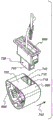
FIG. 4 is an enlarged perspective view of the three-sided Δ LED luminaire of FIG. 1;
FIG. 5 is a perspective view of a four-sided rectangular or square non-curvilinear LED luminaire according to the principles of the present invention;
FIG. 6 is a perspective view of a pentagon non-curvilinear LED luminaire according to the principles of the present invention;
FIG. 7 is an enlarged cross-sectional view of the pentagonal non-curvilinear LED illuminator of FIG. 6;
FIG. 8 is a perspective view of an outdoor menu billboard providing outdoor signage using two-sided Δ non-curvilinear LED luminaires, such as for drive-up food menu billboard applications, showing the menu billboard door partially open, according to the principles of the present invention;
FIG. 9 is an enlarged view of portions of the outdoor menu bulletin board of FIG. 8;
FIG. 10 is a perspective view of an indoor menu billboard, such as for a restaurant, utilizing a three-sided Δ non-curvilinear LED luminaire to provide an indoor sign, with one of the panel doors shown partially open, in accordance with the principles of the present invention;
FIG. 11 is an enlarged view of portions of the indoor menu bulletin board of FIG. 10;
FIG. 12 is an exploded assembly view of a three-sided Δ non-curvilinear LED luminaire according to the principles of the present invention;
FIG. 13 is an enlarged view of the right portion of the three-sided Δ non-curvilinear LED illuminator of FIG. 12;
FIG. 14 is an enlarged view of the left portion of the three-sided Δ non-curvilinear LED illuminator of FIG. 12;
FIG. 15 is an exploded assembly view of a two-sided non-curvilinear LED luminaire according to the principles of the present invention;
FIG. 16 is an enlarged view of the right portion of the two-sided non-curvilinear LED illuminator of FIG. 15;
FIG. 17 is an exploded assembly view of another two-sided non-curvilinear LED luminaire according to the principles of the present invention;
FIG. 18 is an enlarged view of the right portion of the two-sided non-curvilinear LED illuminator of FIG. 17;
FIG. 19 is a perspective view of an end cap connector plate for a two-sided Δ non-curvilinear LED according to the principles of the present invention;
FIG. 20 is a perspective view of a surface mount connector connected to the end cap connector plate of FIG. 19;
FIG. 21 is a perspective view of a portion of a driver board connected to the connected surface mount connector of FIG. 20;
FIG. 22 is a perspective view of a portion of a three-sided Δ heat sink tube positioned around a driver board and against the end cap connector board of FIG. 21;
FIG. 23 is a perspective view of the emitters on the emitter board with AC and DC power traces connected to surface mount connectors and positioned around the radiator tube of FIG. 22;
FIG. 24 is a perspective view of a portion of a lens around the emitter of FIG. 23;
FIG. 25 is a perspective view of a portion of the end cap located at the left end of the lens of FIG. 24;
FIG. 26 is a perspective view of a two-sided Δ non-curvilinear LED luminaire with end caps and showing portions of the lens removed to show the emitters on the emitter board and the AC and DC power traces connected to the surface mount connectors;
FIG. 27 is a perspective view of an end cap connector board or connector end board and driver board of a two-sided Δ non-curvilinear LED luminaire according to the principles of the present invention;
FIG. 28 is a perspective view of a transmitter board connector connected to an end cap connector board and showing the driver connectors connected to the driver board and end cap of FIG. 27;
FIG. 29 is a perspective view of an LED emitter mounted on an emitter board around a heat sink tube and against the end cap connector board of FIG. 28 and showing traces and jumpers;
FIG. 30 is a front view of the end cap connector plate of FIG. 27;
FIG. 31 is a perspective view of a longitudinally end-to-end connected emitter plate for use in a non-curvilinear LED luminaire according to the principles of the present invention;
FIG. 32 is a perspective view of the LED emitter mounted on the emitter board of FIG. 31 and showing the emitter board connector;
FIG. 33 is a schematic delta LED wiring diagram of a three-sided delta non-curvilinear LED luminaire according to the principles of the present invention;
FIG. 34 is a light distribution pattern emanating from a straight row of emitters, sometimes referred to as a "baseline" or "front light incident angle";
FIG. 35 is a light distribution pattern, sometimes referred to as a "back light angle of incidence", emanating from a two-sided Δ non-curvilinear LED luminaire in accordance with the principles of the present invention;
FIG. 36 is a light distribution pattern emanating from a plane of a conventional prior art forward-facing emitter in one or four rows with four light bars six inches apart, sometimes referred to as a "headlight array";
fig. 37 is a light distribution pattern emitted from four light bars of a double-sided Δ non-curvilinear LED luminaire, sometimes referred to as a "headlight array", in accordance with the principles of the present invention;
FIG. 38 is a light distribution pattern emitted from a conventional prior art device, such as for illuminating two-sided outdoor signs, using 180 degree back-to-back two-plane rows of emitters;
FIG. 39 is a light distribution pattern from a three-sided Δ non-curvilinear LED luminaire according to the principles of the present invention and optimized to narrow the dark area of the forward side and create a balance between two dark areas entering primarily the reflector and one area for direct illumination;
FIG. 40 is a light distribution pattern emanating from a single emitter;
FIG. 41 is a light distribution pattern emanating from the group or row of emitters of FIG. 40;
FIG. 42 is a light distribution pattern emanating from a single forward emitter;
FIG. 43 is a light distribution pattern emanating from a group or row of forward-facing emitters of FIG. 4;
FIG. 44 is a graph of operating cost of a non-curvilinear LED luminaire according to the principles of the present invention, where the X-axis is time in years and the Y-axis is U.S. dollars (USD), as compared to conventional LED and fluorescent luminaires.
FIG. 45 is a schematic diagram of a prototype non-curvilinear LED luminaire according to the principles of the present invention;
FIG. 46 is a top view of the prototype non-curvilinear LED illuminator of FIG. 45;
FIG. 47 is a schematic diagram of another prototype non-curvilinear LED luminaire according to the principles of the present invention;
FIG. 48 is an enlarged cross-sectional view of a prototype delta three-sided non-curvilinear LED luminaire according to the principles of the present invention and taken along line A-A of FIG. 47;
FIG. 49 is a bottom view of the non-curvilinear LED taken along line B of FIG. 48;
FIG. 50 is an enlarged cross-sectional view of yet another prototype Δ three-sided non-curvilinear LED luminaire according to the principles of the present invention;
FIG. 51 is a perspective view of a portion of the prototype Δ three-sided non-curvilinear LED luminaire of FIG. 50;
fig. 52 is a perspective view of the pin arrangement in the compact lamp shaped socket;
FIG. 53 shows front and bottom views of the pin arrangement in a compact base for a two pin lamp;
FIG. 54 shows front and bottom views of the pin arrangement in a compact socket for a four pin lamp;
FIG. 55 is a fragmentary, exploded perspective view of one end of a conventional tubular light emitting assembly, with a connector on the body having an illumination source and a cooperating connector on the support;
FIG. 56 is the same view as in FIG. 55, with the bodies aligned, ready for installation;
FIG. 57 is the same view as in FIG. 56 and shows the opposite end of the body and the cooperating connectors on the bracket;
FIGS. 58 and 59 correspond to FIGS. 56 and 57, respectively, and show the body pushed upwardly to engage the cooperating connector;
FIGS. 60 and 61 correspond to FIGS. 58 and 59, respectively, and illustrate turning of the tubes to lock the tubes by the cooperating connectors;
FIG. 62 is a fragmentary perspective view of an elongate tubular light emitting assembly according to the present invention and showing cooperating connector components at one end of the body with an illumination source on or within the body;
FIG. 63 is the same view as FIG. 62 with the connector parts completely separated from each other;
FIG. 64 is the same view as in FIG. 63, showing the cooperating connector components of the opposite ends of the body;
fig. 65 and 66 correspond to fig. 63 and 64, respectively, and show the connector parts snapped together;
FIG. 67 corresponds to FIGS. 63 and 64, and is reduced in size to collectively illustrate the entire body;
FIG. 68 is the same view as in FIG. 67 and corresponds to FIGS. 65 and 66, taken together showing the entire body;
FIG. 69 is the same view as in FIG. 68 with the diffuser cover removed and the illumination source exposed;
FIG. 70 is an exploded perspective view of the tubular light assembly of FIG. 69;
FIG. 70a is a schematic representation of one connector plate at one end of the body as an alternative to two plates for the same end of the body in FIG. 70;
FIG. 71 is an enlarged perspective view of a connector plate including the connector components of FIG. 65 and a source of illumination;
FIG. 72 is an exploded perspective view of the assembly of FIG. 71;
FIG. 72a is the same view as in FIG. 72, but from a different perspective, with a portion of one connector component disengaged;
FIG. 72b is the same view as in FIG. 72a, but with the components assembled;
FIG. 73 is an exploded view of the assembly of FIG. 72 from a different perspective;
FIG. 74 is an enlarged end view of the connector components shown in relation to FIG. 63;
FIG. 75 is the same view as in FIG. 74, with connector parts in the relationship of FIG. 65;
FIG. 76 is the view in FIG. 73 from a different perspective;
FIG. 77 is the same view as FIG. 76, with the connector components connected as in FIG. 69;
FIG. 78 is a schematic representation of a tubular lighting assembly according to the present invention;
FIG. 79 is the same view as FIG. 72 and shows a modified form of one of the connector members cooperating with the cylinder;
FIG. 80 is the same view as in FIG. 79 with the connector parts snapped together;
FIG. 81 is a schematic representation of a modified form of a tubular lighting assembly according to the present invention;
FIG. 82 is a schematic representation of yet another modified form of a tubular lighting assembly according to the present invention;
FIG. 82a is an exploded perspective view of a tubular lighting assembly according to the present invention, generally corresponding to FIGS. 69 and 70, but with the connector assembly and connector plate omitted at one end, as shown in the schematic representation of FIG. 82;
FIG. 83 is an end view of a portion of another modified form of the body in a tubular lighting assembly according to the present invention;
FIG. 84 is a view of still another modified form of the body of FIG. 83 in accordance with the present invention;
FIG. 85 is the view of FIG. 84 with the diffuser cover in a pre-installed position relative to the heat sink; and
FIG. 86 is a view of a still further modified form of the body of FIG. 84 in accordance with the present invention;
fig. 87 is an exploded perspective view of a modified form of a tubular lighting assembly with an uninterruptible power supply located within a heat sink in accordance with the invention.
The following detailed description of exemplary embodiments, taken in conjunction with the various drawings briefly described above, provide a more detailed description of the principles of the invention.
Detailed Description
The following is a detailed description and illustration of a preferred embodiment of the invention, as well as the best mode contemplated for carrying out the invention.
Referring to the figures, fig. 1 is a perspective view of a Light Emitting Diode (LED) illumination assembly 100, the illumination assembly 100 including a suspended LED lighting assembly providing a suspended ceiling light, having: a two by four (2x 4) LED ceiling light fixture 101 has a multi-sided modular LED light bar 102, also referred to as a multi-sided LED light bar. The lighting bar may include a Light Emitting Diode (LED) luminaire 103 of a three-sided delta-shaped non-curvilinear type, the luminaire 103 may be mounted to the ceiling 104, such as by power connector pins 106 extending from a three-sided delta-shaped end cap 108, the power connector pins 106 may reliably engage the light socket 110. Fig. 2 is an enlarged view of portions of a multi-sided LED light bar including an LED ceiling luminaire having the three-sided Δ non-curvilinear LED luminaire of fig. 1. The upright metal face member 112 can provide a stand that can extend integrally between and connect the lamp socket and the suspended metal concave mirror 114. The reflector may be positioned over a three-sided Δ non-curvilinear LED illuminator to reflect light downward toward the floor. The three-sided delta non-curvilinear LED luminaires, sockets and mirrors may be positioned above a light transmissive translucent ceiling 116 (fig. 1) providing a grid or pattern of light transmissive ceiling panels. The ceiling panels may include an elongated light diffuser 117, the light diffuser 117 providing a light transmissive lens for diffusing and/or focusing light emitted from the LEDs onto the floor. The ceilings may be connected by a ceiling grid 118 of longitudinal and transverse rows of ceiling-connectors 120. Fig. 3 is a cross-sectional view of an LED ceiling luminaire with a three-sided delta LED non-curvilinear luminaire and shows an elongated LED emitter Printed Circuit Board (PCB) panel 122, also referred to as a modular LED emitter board. The LED PCB panels may be mounted or otherwise secured on and/or radially outward from the sides of an elongated three-sided, delta or triangular tubular metal heat sink 124 (fig. 1) to form a three-sided delta or triangular array or set of emitter boards. The intersecting faces of the three-sided heat sink may provide corners and vertices of the heat sink, which may be convex, rounded, curved, or chamfered, if desired. An internal non-switching PCB 125 including a driver board may be positioned inside the array to drive the emitter board. Fig. 4 is an enlarged perspective view of a three-sided Δ LED illuminator. Each of the three sided LED emitter PCB panels may contain one or more rows of aligned, equally spaced LED emitters 126 in a group, matrix or array. The heat sink may comprise an extruded aluminum article and may spread the heat generated by the LED emitter and driver.
Fig. 5 is a perspective view of an LED lighting assembly 130 comprising a four-sided modular LED lighting strip 131(LED light bar), providing a four-sided rectangular or square non-curvilinear LED luminaire 132, which LED luminaire 132 may have end caps 133 and outwardly extending power connector pins 134 for securely engaging a light socket. The four-sided LED luminaire may have an elongated four-sided tubular metal heat sink 136, such as made of extruded aluminum. The intersecting faces of the four-sided heat sink may provide corners and vertices 137 of the heat sink, which may be convex, rounded, curved or chamfered, if desired. An elongated LED emitter PCB panel 138 providing a modular emitter board may be mounted or otherwise secured to and/or positioned radially outward from the heat sink in an array of generally rectangular shapes. Each of the LED emitter PCB panels may be rectangular and may contain one or more rows of aligned, equally spaced LED emitters 140. The heat sink may spread heat generated by the LED emitter. The terminals 142 may be connected to an end cap Printed Circuit Board (PCB) connector 144 that includes a connector end plate, also referred to as an end cap plate, which may be secured to the end cap by bolts 146. An internal non-switching PCB driver including a driver board may be positioned inside the array to drive the transmitter board.
Fig. 6 is a perspective view of an LED lighting assembly 150, including a five-sided modular LED lighting bar 151(LED light bar) providing a five-sided pentagonal-shaped non-curvilinear LED luminaire 152. The illuminator may have an end cap 153 and outwardly extending power connector pins 154 for securely engaging a light socket. The pentahedral LED luminaire may have an elongated pentahedral tubular metal heat sink 156, such as made of extruded aluminum. The intersecting faces of the pentagonal shaped heat sink may provide corners and vertices 157 of the heat sink, which may be convex, rounded, curved or chamfered, if desired. An elongated LED emitter PCB panel 158, also referred to as a modular LED emitter board, may be mounted on or otherwise secured to the heat sink and/or secured radially outward from the heat sink to form a pentagon array of LED emitter PCB panels. Each of the five-sided LED emitter PCB panels may be rectangular and may contain one or more rows of aligned, equally spaced LED emitters 160. The terminals 162 may be connected to an end cap PCB connector 164 that includes a connector end plate, also referred to as an end cap plate, which may be secured to the end cap by bolts 166. FIG. 7 is an enlarged cross-sectional view of a pentagonal non-curvilinear LED illuminator. An internal non-switching PCB driver 168 comprising a driver board may be positioned inside the array to drive the transmitter board. The heat sink may spread the heat generated by the LED emitter and driver.
Fig. 8 is a perspective view of an LED lighting assembly 170, including an elongated outdoor menu billboard 171 that may utilize a two-sided modular LED light bar 173(LED light bar) to provide an outdoor sign 172, including a two-sided or delta non-curvilinear LED luminaire 174, such as menu billboard applications for drive-up purchasing of food. Fig. 8 also shows a partially open front menu bulletin board door 176. The front menu bulletin board may include a rectangular frame 178 to surround and secure a light transmissive panel 180, which light transmissive panel 180 may provide a door pocket including an illuminated menu window 182. The menu window may provide an illuminated sign that may include an elongated light diffuser 183, and the light diffuser 183 may provide a light transmissive lens for diffusing and/or focusing light emitted from the LEDs. The front menu billboard door may be pivotally hinged with a hinge or movably attached to the top 184 or one of the sides 186 of the outdoor menu billboard housing 188. The back of the housing may also have a light transmissive panel for illuminating the front and back of the outdoor menu bulletin board, if desired. The double sided delta non-curvilinear LED luminaire can be connected to the light socket assembly 190, such as by power connector pins. The two-sided delta non-curvilinear LED luminaire can be positioned vertically, longitudinally, laterally, transversely, or horizontally inside the outdoor menu bulletin board housing. A menu billboard vertical upright post 192, which may have a rectangular, square, or circular cross-section, may be mounted on the base plate and attached to the top of the menu billboard housing along the vertical center line of the housing to support and lift the outdoor menu billboard housing, door, and illuminated menu window. FIG. 9 is an enlarged view of portions of the outdoor illuminated menu bulletin board of FIG. 8.
Fig. 10 is a perspective view of an LED lighting assembly 200, including an elongated indoor menu billboard 201 that utilizes a two-sided or three-sided modular LED light bar 203(LED light bar) to provide a wall-mounted indoor sign 202, including a two-sided or three-sided Δ non-curvilinear LED luminaire 204 for a restaurant 206 such as, but not limited to, a counter 208, a wall 210, an exit and/or entrance door 214, and a counter 214, and showing one of the menu panel doors 216 in a partially open position. Fig. 11 is an enlarged view of portions of the indoor menu bulletin board of fig. 10. The back 218 of the menu bulletin board may be securely mounted to the wall. The front face of the menu bulletin board may include one or more menu panel doors, such as a set of horizontally aligned menu panel doors or an array of menu panel doors. Each menu panel door may include a rectangular frame 220 to surround and secure a light transmissive panel 222, which light transmissive panel 222 may provide a door apex including an illuminated menu window 224. The menu window may provide an illuminated sign that may include an elongated light diffuser 225, and the light diffuser 225 may provide a light transmissive lens for diffusing and/or focusing light emitted from the LEDs into the room or interior of the restaurant. Each menu billboard panel door may be pivotally hinged with a hinge or movably attached to the top 226 or one of the sides 228 of the menu billboard housing 230. A two-sided or three-sided delta non-curvilinear LED luminaire can be connected to the light socket assembly 232, such as by power connector pins. The two-sided delta non-curvilinear LED luminaire can be positioned vertically, longitudinally, laterally, transversely, or horizontally inside the outdoor menu bulletin board housing.
Fig. 12 is an exploded assembly view of an LED lighting assembly 240, including a three-sided modular LED light bar 241(LED light bar), providing a three-sided delta or triangular shaped non-curvilinear LED luminaire 242. Fig. 13 is an enlarged view of a right portion of the three-sided Δ non-curvilinear LED illuminator of fig. 12. Fig. 14 is an enlarged view of the left portion of the three-sided Δ non-curvilinear LED illuminator of fig. 12. The three-sided delta non-curvilinear LED luminaire may have a metal heat sink 243, such as a three-sided delta triangular shape made of extruded aluminum. The intersecting corners 244 providing the apex of the heat sink may be convex, rounded or chamfered, if desired. The elongated LED emitter PCB panel 246-248 may be mounted or otherwise secured to and/or positioned radially outward from the heat sink in a generally triangular or delta shape. Each of the LED emitter PCB panels may be rectangular and may contain one or more rows of aligned, equally spaced modular LED emitters 250. An internal non-switching elongated Printed Circuit Board (PCB) driver 252, also referred to as a driver board, may be positioned along the length of the heat sink and within the interior area enclosed by the heat sink. The heat sink may spread heat generated by the LED emitter and the PCB driver. The emitter board terminals 254 and 256 may extend longitudinally outward from the LED emitter board. Driver board terminals 258 may extend longitudinally outward from the PCB driver. The delta trilateral shaped non-curvilinear LED luminaire may have a delta trilateral end cap PCB connector 260-. The end cap may have rounded corners 266 or vertices. The power connector pins 268 may extend laterally outward from the connector end plate through connector pin receiving holes 270 in the end cap for fixed engagement with the light socket. The connector end plate may have end cap plate terminals 272 extending longitudinally inward along three faces thereof, which end cap plate terminals 272 may be connected to the transmitter plate terminals. The connector end plate may also have a driver plate connecting terminals 274 that extend longitudinally inward from a central portion of the connector end plate and may be connected to the driver plate terminals. A three-sided delta or triangular shaped cap 276 may provide a rim for positioning around the end cap. As shown in fig. 14, each of the connector end plates may have a central U-shaped concave recess portion 278 between the faces 280 and 282 and may have a lower third face 284 extending below the lower portion of the other two faces. Sides 280-284 may be straight, flat, and planar.
Fig. 15 is an exploded assembly view of an LED lighting assembly 290, including a two-sided modular LED light bar 291(LED light bar), providing a two-sided elongated non-curvilinear LED luminaire 292 similar to the three-sided delta or delta shaped non-curvilinear LED luminaire of fig. 12-14, except that there are only two elongated LED emitter PCB panels 293, including modular LED emitter boards, which may be mounted or otherwise secured on and/or radially positioned outward from two sides 294 and 295 in three-sided 294 and 296 of a three-sided delta or delta shaped metal heat sink 297. The two LED emitter panels may be positioned in a substantially V-shape. Fig. 16 is an enlarged view of the right portion of the two-sided non-curvilinear LED illuminator of fig. 15. Each of the LED emitter PCB panels may be rectangular and may contain one or more aligned, equally spaced rows of LED emitters 298. An internal non-switching elongated Printed Circuit Board (PCB) driver 300 may be positioned along the length of the heat sink and within the interior area enclosed by the heat sink. The heat sink may spread heat generated by the LED emitter and the PCB driver. The emitter board terminals 302 and 304, also referred to as emitter board connectors, may extend longitudinally outward from the LED emitter board. Driver board terminals 306 may extend longitudinally outward from the PCB driver. The two-sided delta-triangular shaped non-curvilinear LED luminaire may have three-sided delta or triangular connector tip plates 308 and 310, including connector tip plates, which triangular connector tip plates 308 and 310 may be secured to three-sided delta or triangular shaped end caps 312 and 314, respectively, by screw holes 318 in the end caps, by fasteners 316 such as bolts, etc. Power connector pins 320 may extend laterally outward from the connector end plate through connector pin receiving holes 322 in the end cap for fixed engagement with the light socket. The connector end plate may have end cap plate terminals 324, also known as surface mount connectors, which end cap plate terminals 324 may extend longitudinally inward along two of its three sides and may be aligned with and connected to the emitter plate terminals. The connector end plate may also have a driver board that connects terminals 326, which extend longitudinally inward from a central portion of the PCB end cap connector plate, and may connect to the driver board terminals. An elongated light diffuser cover 328 comprising a concave translucent or transparent light transmissive lens may cover the LED emitter board for reflecting, diffusing and/or focusing light emitted from the LED emitter. The lens may be made of plastic or glass and may be circular, semi-circular, and positioned radially outward from the LED emitter. The lens may have inward footings 329, which footings 329 may snap around the heat sink.
Fig. 17 is an exploded assembly view of an LED lighting assembly 330 comprising a two-sided modular light bar 331 providing another two-sided non-curvilinear LED luminaire 332, similar to the two-sided non-curvilinear LED luminaires of fig. 15-16, except that there are two sets or arrays 333 of elongated LED emitter PCB panels comprising modular LED emitters that can be mounted or otherwise secured on and/or positioned radially outward from two sides of a three-sided delta or triangular shaped metal heat sink 334. FIG. 18 is an enlarged view of the right portion of the two-sided non-curvilinear LED illuminator of FIG. 17. Each group or array of modular LED emitter PCB panels has more than one LED emitter PCB panel, such as, but not limited to, three elongated LED emitter PCB panels 336 and 338 providing modules that extend, align, and are connected end-to-end longitudinally by emitter PCB panel terminal connectors 340 and 342. Each of the LED emitter PCB panels may be rectangular and may contain one or more rows of aligned, equally spaced LED emitters 343. The LED illuminator may have a three-sided delta or triangular shaped end cap connector 344 including connector end plates that may be secured to the three-sided delta or triangular shaped end cap 346 by bolts or other fasteners through screw holes 348 in the end cap. Power connector pins 350 may extend laterally outward from the connector end plate through connector pin receiving holes in the end caps for secure engagement with the ends inserted into the light socket. The connector end plate may have end cap plate terminals 352, and these end cap plate terminals 352 may extend longitudinally inward along two of its three sides and may be connected with the emitter plate terminals. An elongated translucent or transparent light transmissive plastic lens 354 including a diffuser cover of the diffuser may cover the LED emitter board. The lens may be circular, semi-circular, and positioned radially outward from the LED emitter. The lens may have inward footings 356, and these footings 356 may snap around the heat sink.
Fig. 19 is a perspective view of an end cap PCB connector 360, also referred to as a connector end plate or end cap plate, of an LED lighting assembly including a two-sided LED light bar, the LED lighting assembly providing a two-sided delta or triangular non-curvilinear LED luminaire such as that shown in fig. 15-16. The end cap PCB connector may have a central U-shaped concave recessed portion 362 between two sides including convex curved arcuate sides 364 and 366 and may have a lower third side that may extend under the lower portions of the two convex sides, including straight flat planar sides 368. The PCB connector may have connector pin holes 370, also known as AC power pin connectors or AC hot pin connectors, and electrical traces 372 for connecting electrical components on the end cap PCB connector. As shown in fig. 20, surface mount connectors 374-376, also referred to as transmitter board connectors or end cap board terminals, may connect portions of the connector end boards near the sides of the connector end boards. The surface mount connector of the end cap PCB connector may be connected to a driver board connector 378 (fig. 21), also referred to as a PCB driver connector, of an internal non-switching elongated driver board 380 that includes a driver. A three-sided delta or triangular shaped metal heat sink tube 382 (fig. 22), also known as a tubular heat sink, may be positioned around the driver board and against the cap connector end plate. The heat sink may have upward facing emitter board support channels 384 and 386 along its bottom edge to support an elongated LED emitter PCB panel 388 (fig. 23), also referred to as a modular LED emitter board. The LED emitter PCB panel may be mounted or otherwise secured to and/or positioned radially outward from the heat sink to form a V-shaped array. Each of the LED emitter PCB panels may contain one or more rows of aligned, equally spaced LED emitters 390. The heat sink may spread the heat generated by the LED emitter and the driver board. The emitter plate connector 392, also referred to as an emitter plate terminal, may extend from the end of the emitter plate and connect to a surface mount connector including an end cap plate terminal of an end cap PCB connector. The emitter traces 394 may connect the LED emitters in series, while the end traces 396 may connect the emitters to the emitter board connector. An Alternating Current (AC) power trace 398 may be positioned parallel to the additional trace 399 and the Direct Current (DC) trace 400 on the transmitter board. An elongated translucent or transparent light transmissive lens 402 (fig. 24) including a diffuser cover or diffuser may cover the LED emitter board. The lens may be circular, semi-circular, and/or positioned radially outward from the LED emitter. The elongated, longitudinally lower end 404 of the lens may include a foot and may be received in and supported by the channel of the heat sink. An end cap 406 (fig. 25) may be positioned around the end of the lens and the end cap PCB connector. Fig. 26 is a perspective view of a three-sided delta or triangular non-curvilinear LED luminaire with end caps and shows portions of the lens removed to show the emitter on the emitter board and the AC and DC power traces connected to the surface mount connectors. As shown in fig. 26, the end caps may have curved, concave brackets 408 comprising bracket segments that may extend longitudinally inward and may provide clips positioned around the perimeter of the end caps to securely engage, clamp, bite, capture and retain the top ends of the emitter plates.
AC traces 410 (fig. 27) and DC traces 412 may be connected to driver circuits 414 on driver board 380. The driver connector 378 (fig. 28) may be connected to the driver circuitry and to a surface mount connector 375, also referred to as an emitter board connector, of an end cap PCB connector (connector end plate or end cap plate) 372. In some arrangements, the end cap connector plate may have male connectors 377 with connector pins 379 extending longitudinally inward to matingly engage and insert into female connectors on the transmitter plate, and/or the driver plate and end cap connector plate may have female connectors 374 to receive and insert longitudinally outward into connector pins of matingly engaged (mated) male connectors on the transmitter plate and/or driver plate. In the illustrated embodiment, there are four pin connectors at the end of each emitter board and driver board, although for some longer light bars, six pin connectors may be required.
The end cap PCB connector may have a DC power terminal 416 (fig. 30) to conduct Direct Current (DC) to the three LED strings and a DC return terminal 418 to receive DC from the LEDs. The AC neutral trace 420 may extend from the opposite side. The end cap PCB connector may also have an AC neutral terminal 422 and an AC hot terminal 424.
Fig. 29 is a perspective view of an LED emitter mounted on a modular LED emitter board around a heat sink tube (tube heat sink) and against an end cap connector board. The transmitter may have additional traces 426 connected to the transmitter board connector to transmit AC or DC from the opposite side or end of the transmitter board. The transmitter board may also have a regulated DC return trace 428 connected to the transmitter board connector and series-parallel patch cords 430. The figure shows how the drive is connected to the connector end plate in a configuration with both sides of a female and male connector. In some arrangements (modules) only one end cap plate is required, in the W configuration the emitter plates are designed within a built-in electrical cycle that sends electrical signals through both emitter plates.
The end cap plate may have power pins that are directly soldered, without wires. The driver board can be inserted directly into the tube (tubular array) and positioned inside the tube. Each transmitter board can be plugged in directly without wires. Additional traces are used, if desired, to eliminate the need to run main power wires in the tube (heat sink).
Fig. 31 is a perspective view of modular transmitter boards 432 and 434, such as depicted in fig. 17 and 18, connected end-to-end longitudinally. The emitter board may have a printed emitter board circuit 436 and sub-circuit 438. Fig. 32 is a perspective view of an LED emitter 390 and series-parallel jumpers 430 mounted on the emitter board and shows emitter board connectors 440 and 442 including emitter PCB panel terminal connectors to which the ends of the emitter board can be connected.
Fig. 33 is a schematic delta LED wiring diagram of an LED lighting assembly, including a three-sided LED light bar (LED light bar), providing a three-sided delta or triangular shaped non-curvilinear LED luminaire. The luminaire may have three sides, including rows 450 and 452 of modular LED emitter boards. Each row may be connected in parallel to end cap PCB connectors (connector end plates or end cap plates) 460 and 462 by transmitter end traces 454-459. Each row of LED emitter boards may include three aligned modular LED emitter boards 464-466 that may be connected in series with each other by emitter serial traces 468 and 470. The transmitter end traces may include independently DC-regulated return lines (traces) 457-. A common DC outlet line (trace) 474 may be connected to the driver board in parallel with the return line of the independent DC regulation. The common DC out line may be connected to the end cap PCB connector 460 through the end cap PCB connector 462, through the LED emitter boards of the bottom row 452, and in parallel to and extending from the emitter end traces 454 and 456. AC lines (traces) 476 may extend from the driver board to the end cap 462 and outward, such as, but not limited to, to another electrical component or an AC power source. An additional AC line (trace) 478 may extend from the driver board to the end cap PCB connector 460 through the end cap PCB connector 462 and the top row of LED emitter boards 450, omitting the need for a line for transmitting AC. The wiring pattern may include many varying parallel paths on each transmitter board that allow for series-parallel electrical connections, such as by using jumpers on the transmitter boards.
The wiring diagram of fig. 33 shows the elimination of all the wires. Although the figure shows what appears to be a jumper cable between the driver and the end cap, there is only one connector because they are directly connected. More specifically, an Alternating Current (AC) is present on both end caps; "hot" on one side and "neutral" on the other side. One side of the AC is fed along a string of emitter boards to a main end cap (shown on the right of fig. 33) where it encounters the other half of the AC and is fed to the driver board. The driver board converts the AC to Direct Current (DC) and sends the DC current on one trace through the extra traces on one row of transmitter boards to the secondary end cap where it is combined to apply the same high voltage DC to each string of transmitters. On the low side of each string of emitters, there is a separate trace back to the driver with a separate current control driver that controls the current to each string of emitters individually with high accuracy. The wiring diagram is simplified because in reality there are multiple traces through each emitter board so that any one board can be assigned to any sub-driver.
The wiring diagram shows an example with three strings of three transmitter boards: driver portion "a" has the top three emitter boards, driver portion "b" has the middle three emitter boards, and driver portion "c" has the bottom three emitter boards, however, ultimately to achieve redundancy, they may actually be connected so that the driver is responsible for the three boards, and will not light emitter boards next to each other.
Example, in this case, the transmitter board: driver combination:
AAA
BBB
CCC
if a sub-driver a, B or C fails, or any emitter in the string fails, one third of the light will be lost on that entire side. However, a real line would look like this:
ABC
CAB
BCA
now, if or when one driver branch circuit fails, two thirds of the light will be retained, with the blind spot surrounding the lamp, so there is only one dark spot, rather than being totally extinguished.
Parallel traces may be used in a preferred layout. The board may have preformed traces. Parallel traces are used, if desired, to allow electrical energy to reach the transmitter in an electrically efficient manner. The advantage of using parallel traces is that all emitters are driven at exactly the same current and power level. In most conventional designs, this is not the case. A further advantage of the series-parallel circuit arrangement is that we can illuminate at higher voltages and lower currents, so that it is more efficient regardless of which driver is used. This is an important aspect of this layout. Further, a multi-channel driver having a plurality of channels may also be used. In one particular mode, six boards are wired in three different ways.
Light distribution patterns are shown in fig. 34-43. Fig. 34 is a light distribution pattern emanating from a straight emitter row, sometimes referred to simply as a "baseline" or "front light angle of incidence". The total angle is approximately 150 degrees of usable light, but at the outer edge of the cone, the attenuation drops to 20% of the peak brightness. The Y2 luminance angle (the angle outside the peak Y2 in luminance less on axis intensity) is about 120 degrees in a very good emitter, (60 degrees off axis in a 360 degree cone). When the emitters are used in whole rows and columns, the rows represent the PCB and the columns represent the light bars, the light distribution is not uniform since the columns are scattered, since the spacing on the rows will be closer than the spacing on the columns due to practicality.
Fig. 35 is a light distribution pattern emitted from a double-sided Δ non-curved LED luminaire, sometimes referred to as a "rear light incidence angle". The center brightness is much wider and the fact that the beam width is greatly improved is clearly visible. The full angle is approximately 230 degrees, which is greater than 150 degrees of usable light. The Y2 brightness angle increases from about 120 degrees up to over 180 degrees, which is not possible with conventional single row emitters.
Fig. 36 is a light distribution pattern emanating from a plane of a conventional prior art forward emitter in one or four rows with four light bars six inches apart, sometimes referred to as a "headlight array". Fig. 36 is a light distribution pattern emanating from a plane of a conventional prior art forward emitter in one or four rows with four light bars six inches apart, sometimes referred to as a "headlight array". Only the forward-facing row of emitters forms an almost circular light pattern with significant attenuation outside this "hot spot" region. A better solution can be achieved by placing multiple copies of the rows on each column to form an angle away from each other that is optimized for each use. Such as light reflected from a mirror or directed toward the object being illuminated. Here an example of a cross section of light, two rows of emitters angled away from each other at an optimized angle are used to combine the two beams into one smooth continuous beam as if it were a row of wider angled emitters.
Fig. 37 is a light distribution pattern emitted from four light bars of a double-sided Δ non-curved LED luminaire, sometimes referred to as a "headlight array. The array of delta LED light bars will have a light distribution similar to that of fig. 37. This is a much smoother, much wider light distribution of the light pattern with less dark and less bright areas. This same concept also applies when going around a pipe. A perfect light pattern can be achieved with a pentagonal hexagonal or heptagonal extrusion, but the difference between using two-sided and three-sided LED light bars is shown here.
Fig. 38 is a light distribution pattern emitted from a conventional prior art arrangement, such as for illuminating two-sided outdoor signs, using 180 degree back-to-back two-plane rows of emitters. Fig. 39 is a light distribution pattern from a three-sided delta or triangular non-curvilinear LED luminaire and optimized to narrow the dark area of the forward side and create a balance between two dark areas entering mainly the reflector and one area for direct illumination. With only three rows, an absolutely uniform light distribution is physically impossible, but by adjusting the angle we can improve the forward light. Although there is a slight dim area directly up from the center, the light distribution pattern is improved over two dim areas, i.e. the central "southeast" and "southwest" areas. The improved LED light bar can be mounted in such a way as to eliminate any artifacts from those dim areas. When using a four-sided tubular LED light bar, the light pattern becomes almost uniform. When a five-sided tubular LED light bar is used, the light mode achieves substantially a 360 degree uniform light distribution.
Fig. 40 is a light distribution pattern emitted from a single emitter. FIG. 41 is a light distribution pattern emanating from a group or row of emitters of FIG. 40. Fig. 42 is a light distribution pattern emanating from a single forward emitter. FIG. 43 is a light distribution pattern emanating from a group or row of forward-facing emitters of FIG. 4.
FIG. 44 is a graph of operating costs and capital costs for a non-curvilinear LED luminaire compared to conventional LED and fluorescent luminaires, where the X-axis is time in years and the Y-axis is U.S. dollars (USD). The capital cost of replacing a light bar (LED light bar) extending to 48 inches long including a delta or triangular shaped LED luminaire 480 is shown in the figure with the lowest cost. The capital cost of replacing the 48 inch fluorescent bulb 482 operating at 65 watts is a higher cost. The operating cost of a high efficiency Δ or triangular shaped LED luminaire 484 that is 48 inches long and emits 3000 lumens (L) is shown in the graph, with the lowest operating cost. 48 inches long and emitting 3600L of more intense light, but with more power, the high output Δ or triangular shaped LED illuminator 486 with the same number of emitters as LED illuminator 484 can operate at a slightly more cost than a high efficiency LED illuminator. A typical prior art LED luminaire 486 is shown in the graph, which has a higher operating cost than delta-triangular shaped LED luminaires 484 and 486. The operating cost of an existing 48 inch 65 watt (W) fluorescent tube 488 including a ballast is much more expensive than the delta-triangular shaped LED illuminators 484 and 486. It is graphically shown that the operating cost of operating the power of the newly installed fluorescent tube 490 is most expensive.
When referring to brightness versus power, the correct term is efficacy or lighting efficacy, which may be expressed in lumens per watt. When referring to a light bar or its components, electrical efficiency can be expressed in watts of power entering the system versus how many watts are delivered to the transmitter itself. Lifetime can be expressed in thousands of hours. Typically, fluorescent tubes will last from 8 to 10,000 hours. When used as a fluorescent replacement product, conventional LEDs are at best almost identical to fluorescent lamps when driven sufficiently. High quality SMD high power LEDs will last for about 50,000 hours when driven to specification and over 70,000 hours when under driven. The model of lighting described in this patent application can be optimized to almost 100% efficiency for the light bar itself, that is, 100% of the watts going into the light bar is delivered to the emitter. This is because the line goes directly to the transmitter, without much power loss on the trace. When the number of emitters is optimized to the input voltage, there is a huge gain in the efficiency of the whole system, so that very efficient electric drives can be used. With the LED light bar of the present invention, four to five times improvement over conventional efficiency can be achieved.
Fig. 45 is a schematic diagram of a prototype non-curvilinear LED luminaire. Fig. 46 is a top view of a prototype non-curvilinear LED illuminator.
Fig. 47 is a schematic diagram of another prototype non-curvilinear LED luminaire. Fig. 48 is an enlarged cross-sectional view of the prototype delta three-sided non-curvilinear LED luminaire taken along line a-a of fig. 47. Fig. 49 is a bottom view of the non-curvilinear LED taken along line B of fig. 48.
Fig. 50 is an enlarged cross-sectional view of yet another prototype Δ three-sided non-curvilinear LED luminaire. Fig. 51 is a perspective view of a portion of the prototype Δ three-sided non-curvilinear LED luminaire of fig. 50.
Fig. 52 is a perspective view of the pin arrangement in a compact lamp shaped socket. Fig. 53 shows front and bottom views of pin arrangements in a compact base for a two pin lamp. Fig. 54 shows front and bottom views of pin arrangements in a compact socket for a four pin lamp.
In describing the preferred embodiments of the present invention illustrated in the drawings, specific terminology is employed for the sake of clarity. However, the invention is not intended to be limited to the specific terms so selected, and it is to be understood that each specific term includes all technical equivalents which operate in a similar manner to accomplish a similar purpose. For example, the words "connected," "attached," or terms similar thereto are often used. They are not limited to direct connection, but include connection through other elements where such connection is recognized as being equivalent by those skilled in the art.
The present invention and the various features and advantageous details thereof are explained more fully with reference to the non-limiting embodiments that are described in the detailed description of the invention. Aspects of the invention may relate to providing electrical enclosures, device frames, and lightweight luminaire bodies for luminaires that are illuminated by Light Emitting Diodes (LEDs). The present invention may also address issues related to thermal management, heat sinks, and power integration. A more compact LED orientation can be achieved with improved management of the thermal operational load.
Fig. 47 shows an existing light emitting device 510 retrofitted for a Light Emitting Diode (LED) stack. A driver 502 for LED power is provided. The shaft 503 is connected to the LED power strip 504. The LED bulb 505 is connected to the LED feed bar and the power cord 506 is connected to and supplies power to the LED feed bar.
Fig. 45-51 illustrate a Light Emitting Diode (LED) illuminator 510 according to one embodiment of the invention. The illuminator 510 includes a socket 512 that is preferably designed to movably cooperate with a base 514. Regardless of the particular configuration of the base 514, the base is generally understood to be the portion of the luminaire that houses the luminaire and provides electrical connections between the luminaire and the luminaire. In one embodiment, the socket and base are designed to cooperate in a screw-on manner common to many different types of luminaires. Alternatively, the socket and base may be designed in any number of corresponding mating configurations. Many such matching configurations are shown in fig. 52-54. It should be understood that such interaction may be provided in many configurations, with or without screwing and/or twisting interaction between the socket and the base.
Referring back to fig. 45 and 46, an optional post 516 extends between the socket and the base or support 518. The cradle includes one, and preferably a plurality of individual Light Emitting Diodes (LEDs) 520, with the LEDs 520 being supported in an offset orientation from the socket. Preferably, the support may be configured to isolate the LED from air. It will also be appreciated that the support may form a lens or outermost translucent structure of the illuminator, and/or be positioned very close to the lens for those cases where a supplemental lens is included near the support 518.
A plurality of conductors or electrical connectors 522 and 524 may deliver electrical energy to the receptacle, the electrical energy being represented by an exemplary power source 526 and/or switch 527. Conductors 522 and 524 may pass through optional post 516 to the bracket. The rack 518 may be provided with a plurality of traces that are distributed around the rack and electrically connect each LED to a power supply 526. As further explained below, it should be understood that one or more power modifying devices, such as a current transformer or driver, may be positioned between the LEDs and the power supply. The LED 520 may be oriented on each of the opposing sides 528 and 530 of the generally planar shape of the bracket 518 of the luminaire.
As shown in fig. 47, a protective shield or reflector 530 may be oriented around the illuminator 510 and configured to redirect light emitted from the upward LEDs on the upward side 530 of the support in a generally downward direction, indicated by arrow 534 (fig. 48), to improve the illumination performance of the illuminator. The LEDs are preferably evenly distributed around the support.
Referring to fig. 47-49, another alternative configuration of the illuminator includes generally planar, multi-faceted, hollow posts 544, the posts 544 extending in a longitudinal direction between the receptacle 512 and the bracket 518. As shown in fig. 48, in one embodiment of the invention, the post includes three walls 546, 548, and 550 forming a substantially equilateral triangle. Although shown as having a triangular shape, it should be understood that the struts may be provided in other generally linear or substantially non-curvilinear cross-sectional shapes. As described further below, such a configuration would increase the area available for the LED fixture and provide a beneficial configuration for power supply, heat dissipation, and integration of operation control devices, such as device drivers within the footprint of the luminaire, without the need for external structures for packaging such components. As shown in fig. 48, the cavity 552 enclosed by the post 544 is sized to accommodate electrical components associated with the live operation of the LED, such as a driver, a heat sink, a circuit board, electrical and/or thermal components 556.
Fig. 50 and 51 show an illuminator 560 according to another embodiment of the invention. The illuminator may include an elongated body 562, which may include a plurality of faces 564, 566, 568, which may also be oriented in a linear or non-curvilinear manner. Unlike illuminator 510, illuminator 560 includes a socket 570 generally facing one end of the illuminator. A plurality of individual LEDs 572 can be distributed around at least one, and preferably more than one, or each, of the sides 564, 566, 568 of the luminaire. The space 573 enclosed by the faces 564, 566, 568 and the socket 570 may house electronic and/or thermal devices, such as power supplies and/or electronic drivers, heat sinks and/or other thermal control structures, and/or controllers associated with the operation of the LEDs. As shown in FIG. 51, in another embodiment, a plurality of LEDs 572 are supported by each face 564, 566, 568 of the illuminator 560. Such an orientation may increase the range of light output associated with luminaire 560 compared to conventional prior art luminaires having similar spatial requirements. Although the LED 572 is shown supported on a lens forming the structure of the illuminator 560, it should be understood that the LED may also be supported on an internal feed strip or circuit board having a substantially similar shape as the illuminator and may be oriented in close proximity to the inner surfaces of the faces 564, 566, and 568. Such an LED fixture may translate longitudinally relative to the outer surface of the luminaire during assembly. The LEDs can be integrated into each of the faces 564, 566, and 568 such that each of the respective plurality of faces of the luminaire forms a lens and isolates the LEDs from air.
The shape of the frame, the packaging configuration, and considerations for thermal management may allow for placement of the LEDs over a wider surface area than known conventional luminaires. Such a distributed placement of the LEDs may result in a greater degree of light dissipation and a greater light output. In a preferred embodiment, the non-circular or rectilinear orientation of the LEDs may allow for multiple three surface points for placement of a single light source. Preferred embodiments may include a frame package and thermal management channels that also allow for selective internal or external placement of a power source for powering the light source. Regardless of how close the power supply is, the luminaire can be better thermally managed to achieve good heat dissipation. In a preferred embodiment, the luminaire has a three-sided, triangular or delta cross-sectional shape. It should be understood that the illuminator may have any number of generally non-curvilinear shapes, including square or nearly any number of planar sides. When provided in a delta or triangular shape, it should be understood that the illuminator can be provided in almost any shape, including equilateral and/or isosceles triangular shapes. By using a plurality of planar surface structures, a large variation of the orientation and position of the luminaire is possible, and a wide mounting area is possible, providing a strong light.
It is envisioned that the socket of the luminaire may be configured to cooperate with almost any base socket, including, but not limited to, those shown in fig. 52-54. Such a base may also include other bases. It is envisioned that the illuminator of the present invention may be provided in a shape suitable for any base configuration. The luminaire may be configured to operate in a range of about 1 watt to about 1000 watts or more of power. The illuminator may provide a full kelvin color range and may be configured to operate at all voltages, including the most common voltages, such as 12v, 24v, 110v, 120v, 208v, 277v, and 480 v. It is further understood that the illuminator can be provided in almost any length, including lengths from about 2 inches to about 96 inches or more, as well as lengths common in the lighting industry.
The disclosed luminaire may have a larger surface area of LED light sources than any known conventional luminaire having a similar footprint. The configuration of the luminaire may also allow for the placement of power sources inside or outside while providing better thermal management, greater light output, and a greater degree of light spreading. The luminaire may employ a suitable plug and play configuration to provide enhanced LED lighting suitable for operation with conventional fluorescent-type lighting.
The present invention can provide a relatively large surface area for placement of the LEDs to increase light output and provide a greater degree of light diffusion. This may allow for the placement of an internal or external power source, controller, connection, and/or thermal control device. The triangular shape may allow up to three points for lamp surface and thermal management to provide a larger operating range and improved power management for the luminaire.
An improved Light Emitting Diode (LED) lighting assembly may include a multi-sided modular LED light bar, also referred to as a multi-sided LED light bar, including a non-curvilinear (LED) luminaire having a multi-sided elongated tubular array with a plurality of sides, including a modular plate that may define panels with longitudinally opposing ends. The tubular array may preferably have a non-curvilinear cross-sectional configuration without a circular cross-sectional configuration, an elliptical cross-sectional configuration, and a substantially circular or circular curved cross-sectional configuration. Each of the plurality of faces of the multi-faced tubular array may have a generally planar surface, as viewed from the end of the array, and adjacent sides that intersect each other and converge at an oblique angle. There may be an internal non-switching Printed Circuit Board (PCB) driver, including a driver board, operably positioned and connected to the multi-sided array. The driver may be an inner driver plate located inside the tubular array, or may be an outer driver plate that includes and provides one of the sides of the tubular array. Desirably, both or some of the faces include modular LED emitter boards that can provide an elongated LED PCB panel. The internal driver, including the driver board, may drive the LED emitter board and may include one or more modular driver boards in series and/or parallel with each other.
An improved LED lighting assembly, including a multi-faceted light bar, providing a non-curvilinear (LED) luminaire, can have an optimal number of LED emitters, including a set, a matrix, a string, a plurality or an array of Light Emitting Diodes (LEDs) reliably positioned, mounted and arrayed in each of the emitter panels for emitting and distributing light outwardly from the emitter panels in a light distribution pattern for enhanced LED lighting and operating efficiency.
An end cap PCB connector providing a connector end plate, also referred to as an end cap plate, may be positioned at the end of the tubular array and connected to the internal driver board and the transmitter board. The connector end plate may have power connector pins that may extend longitudinally outward to engage and provide a power connection with the at least one light socket. The end cap may be positioned around the end cap PCB connector. The end caps may have carrier segments that may provide inwardly longitudinally extending clips for engaging, clamping and capturing the emitter plates adjacent.
The board comprising the emitter board and the driver board may be rectangular and modular. Each of the faces of the multi-face array comprising transmitter plates comprises a single transmitter plate, or a group, string, plurality of elongated transmitter plates connected end-to-end longitudinally. The faces comprising the emitter plate may comprise all faces of the tubular array, or all but one of the faces of the tubular array, one other face comprising the driver plate. The driver board may comprise a single driver board or a plurality of driver boards connected longitudinally end-to-end. The boards may have male and female connectors that matingly engage such that connectors on the connector termination board matingly engage, connect and plug into matingly engaged female and male connectors on the driver board and/or transmitter board.
A faceted tubular heat sink comprising a plurality of metal facets may be positioned radially inward from the faceted tubular array for supporting and diffusing heat generated from the emitter and driver boards. The heat sink may have a tubular cross-section that may be substantially complementary or similar to the cross-sectional configuration of the faceted tubular array. The cross-section of the heat sink preferably has a non-curvilinear cross-section without a circular cross-section, an elliptical cross-section, and a substantially curved or circular cross-section.
An improved LED lighting assembly including a multi-sided light bar providing a non-curvilinear (LED) luminaire may have emitter traces for connecting LED emitters in parallel and series, and may have Alternating Current (AC) and/or Direct Current (DC) lines. The emitters may comprise at least one row of substantially aligned, equally spaced, evenly spaced LED emitters. Ideally, the multi-faceted light bar provides a cordless design without electrical cords.
An improved LED lighting assembly includes a multi-faceted light bar providing a non-curvilinear (LED) luminaire, and may also have a diffuser including an elongated light diffuser cover that may provide a light transmissive lens that may be positioned around and cover the LED emitter for reflecting, diffusing and/or focusing light emitted from the LED emitter.
In one embodiment, the light bar includes: two-sided modularized LED light-emitting strips; the array comprises a two-sided array; the heat sink comprises a heat sink with at least two sides; and the emitter plates are arranged in a substantially V-shaped configuration and form a certain angle of inclination from less than 180 degrees to an angle greater than zero degrees; and the driver is positioned near the open end of the V-shaped configuration.
In another embodiment, the light bar includes: the LED light-emitting strip is modularized on three sides; the array comprises a three-sided delta or triangular array; the radiator comprises a tubular three-side radiator with a delta or triangular section; and the angle of inclination may vary from some angle less than 180 degrees to greater than zero degrees, preferably 120 degrees. The actuator may be positioned inside the delta or triangular cross section of the three-sided heat sink.
In yet another embodiment, the light bar includes: four-side modularized LED light-emitting strips; the array comprises a square or rectangular array; the heat sink comprises a tubular four-sided heat sink having a square or rectangular cross-section; and the angle of inclination may be a right angle of about 90 degrees.
In yet another embodiment, the light bar includes: a five-sided modular LED light bar; the array comprises a pentagonal array; the radiator comprises a tubular pentahedral radiator with a pentagon section; and, the angle of inclination of the intersecting faces of the pentagons may include an acute angle such as about 72 degrees.
Multi-sided LED light bars, arrays, and heat sinks with more than five sides may also be used.
The improved LED lighting assembly may include an LED sign, such as an outdoor sign or an indoor sign, that is illuminated. The outdoor sign may include an outdoor menu bulletin board, such as in a restaurant for food purchases at drive-up. The indoor sign may include an indoor menu billboard, such as for use in an indoor restaurant. LED signs for display and other uses may also be provided. The illuminated LED sign may include: a housing having a light socket; providing at least one light transmissive panel connected to an illuminated window of the housing; a multi-sided modular LED light bar, also known as a multi-sided light bar, of the type described above, connectable to a light socket for emitting light through an illuminated window; and the illuminated window may be changed from the closed position to the open position to reach the LED light bar. The light bar may extend vertically, horizontally, longitudinally, transversely, or laterally along portions of the housing. The illuminated window may be covered by a diffuser.
The improved LED lighting assembly may further comprise: a suspended LED lighting assembly providing a suspended ceiling light, having: a translucent ceiling comprising a light transmissive ceiling tile; at least one ceiling light fixture including a light socket; and at least one multi-sided modular LED light bar (multi-sided light bar) of the type described above connected to the light socket and positioned above the ceiling for emitting light in a generally downward direction through the translucent ceiling and diverging in a direction toward the floor or room. One or more concave reflectors may be positioned over the LEDs to reflect light downward through the translucent ceiling into the room.
Many advantages of Light Emitting Diode (LED) lighting assemblies equipped with a multi-sided LED light bar comprising a non-curvilinear LED luminaire are:
1. excellent product quality.
2. Outstanding performance.
3. Excellent illumination.
4. Improved LED lighting.
5. Excellent resistance to cracking and impact.
6. Long service life.
7. Is friendly to users.
8. And (4) reliability.
9. Can be easily moved.
10. The weight is light.
11. Is portable.
12. Is convenient.
13. Easy to use and install.
14. The time required for replacing the light bar is short.
15. And (4) durability.
16. Is economical.
17. The appearance is beautiful.
18. And (4) safety.
19. The efficiency is high.
20. Is effective.
The LED lighting assembly of the present invention having a novel multi-sided LED light bar comprising a non-curvilinear LED luminaire has a number of other advantages over conventional LED lighting.
1. The use of a multi-faceted light bar allows for a very wide light distribution. The standard solution has about 100-110 degree beams to half brightness. However, the LED illumination assemblies of the present invention with the novel multi-faceted LED light bar can achieve a full 360 degrees with little or no loss in brightness. Further, the double-sided design shown can exceed 180 degrees to half the brightness. Another advantage is close range use; it is possible to illuminate something just a few inches from the light source.
2. The internal driver of the improved LED lighting assembly with the multi-faceted light bar is less expensive, uses less labor, is simpler, and has a lower probability of failure than conventional lighting.
3. The non-switching driver of the improved LED illumination assembly with the multi-faceted light bar provides an efficiency increase of 4-7 orders of magnitude. Typical switch drivers used on conventional LED light bars have a typical efficiency of 80-85%, or 15-20% loss. In contrast, an improved LED illumination assembly with a multi-faceted light bar may have an efficiency of 95-97% (3-5% loss), four to seven times higher than conventional illumination, which improvement would result in an overall efficiency gain of approximately 20%. Ideally, an improved LED lighting assembly with a multi-faceted light bar is capable of achieving efficiencies greater than 90%, which is nearly impossible to achieve with conventional switch drivers.
An improved LED lighting assembly with multi-faceted light bar ideally enables optimization of the number of emitters for a voltage source and can beneficially use the wiring of a suitable number of emitters in a series-parallel layout.
In an improved LED illumination assembly with a novel multi-faceted light bar, the diffuser including the lens may be modified to vary the output of the light beam. By using this arrangement, dark spots can be eliminated, and thus a much higher illumination output can be achieved. An improved LED illumination assembly with multi-faceted light bars can emit a 360 degree beam without significant hot or cold spots. The improved LED illumination assembly with the multi-faceted light bar may also have a scalable length, as there is no theoretical limit to the length of the novel layout and design. However, the actual length may be limited by customer requirements, cost, available space, and throughput.
An improved LED lighting assembly with multi-sided light bars may further have driver redundancy for better reliability by using parallel and multi-driver subcircuits. This can achieve two other important goals:
1. an improved LED illumination assembly with a multi-faceted light bar achieves a uniform, consistent, accurate power level to all emitters. In contrast, conventional LED designs do not uniformly control the current to all emitters, but rather apply a metered amount of current to all parallel circuits, typically up to three to eight, and since there is no control over the subcircuits, the current can vary across each parallel circuit. An improved LED illumination assembly with a multi-faceted light bar can independently control each branch circuit so that each emitter in the overall illumination assembly gets exactly the same current.
2. An improved LED lighting assembly with multi-faceted light bars achieves output reliability in normal operating positions and even in the event of a branch circuit failure.
In a conventional LED design with an output of 300mA to three subcircuits, when one subcircuit fails, both subcircuits will share the same 300mA, and as such, they will go from 100mA to 150mA, which is a large change in current, is undesirable, and may lead to cascading failures. In an improved LED lighting assembly having a multi-faceted light bar, if one branch circuit fails, the remaining circuits still operate as before the failure.
Further, in an improved LED lighting assembly having a multi-faceted light bar, the branch circuits may be distributed such that no portion of the lighting assembly is completely dimmed, but only slightly dimmed. This is important when illuminating a sign so that the sign will glow brightly and be readable, although perhaps slightly darker at one point.
In conventional LED lighting, all emitters are typically connected in series with each other, so in the event of a single LED failure, the entire row will go out and the entire lighting assembly will go out. In an improved LED lighting assembly having a multi-sided light bar, the emitter strings or groups are aligned and connected in parallel with other emitters so that, in the event of failure of one branch circuit, the LED lights of the LED lighting assembly are only 50% bright, but emit light uniformly from side to side.
The improved LED lighting assembly with the multi-faceted light bar also achieves efficiencies above the initial capital cost. Conventional LED designs attempt to maximize the lumens of each emitter, and are designed according to the specifications of the emitter. Emitters operating according to specifications total approximately 80 lumens per watt.
Improved LED lighting assemblies with multi-faceted light bars can be specifically underdriven to achieve certain very valuable goals:
1. longer service life. For example, a transmitter operating at 70% of rated capacity will last 70-80,000 hours when specified as 50,000 hours. When operating 24 hours a day for seven days a week, that is a difference of 8.6 and 5.7 years.
2. Higher efficiency. An improved LED illumination assembly with a multi-faceted light bar can achieve a total of over 100L/W system by detuning the current drive of the emitter. An improved LED illumination assembly with a multi-faceted light bar can achieve the same overall output by adding more emitters. The initial cost may be higher, but the operating cost will be much lower. This is shown in the operating cost graph shown, which compares a high output 3600L LED light bar with a high efficiency 3000L LED light bar of identical design, but at different driving operating levels, the LEDs being more efficient and having a longer life when driven below specification.
3. Higher reliability. If the temperature is proportional to the LED drive current over their expected lifetime, they will keep the lumens and the color temperature longer when the LED emitter is cooler. An overdriven LED will lose color temperature accuracy faster than a LED driven to specification. Under-driven LEDs can keep the lumens and color temperature even longer than LEDs driven to specification.
The improved LED lighting assembly can have a cordless design such that the novel light bar of the improved LED lighting assembly is cordless. This arrangement can reduce assembly time, reduce assembly problems, and reduce failure rates associated with the complexity of the hand-mounted portion of the assembly. A conventional LED light bar would have 12 or more hand-made solder joints. The new light bar design of the present invention may include only two hand-made solder joints and 100% wire omission. Omitting the standard wire can improve initial reliability and long-term reliability.
The embodiments described above use a driver board comprising circuitry to convert AC to DC for driving LEDs using a DC power supply of the correct electrical polarity. The driver board adds to the overall component, assembly and design costs of the tubular LED lighting assembly and requires additional space in assembly. Typically, converting from AC to DC produces power losses in the range of 15% or more. Driver components, such as rectifiers to convert AC to pulsed DC, and filters to smooth the signal to a constant DC voltage, have a high failure rate compared to other relatively long-lived components of tubular LED lighting assemblies. The use of highly reliable components is important, however, adds considerable cost and may require complex designs.
LED-based solid state lighting offers the opportunity for significant reductions in the carbon footprint of the power grid due to significant reductions in active power consumption. However, if the power factor is not managed, the grid will still need to be able to provide much higher power levels on the load than actually needed, negating a number of the advantages of going to solid state lighting. The power factor is the unitless ratio of active power to apparent power. Active power is the power used on a load measured in kilowatts (kW). Apparent power is a measure of the power in volts-amperes (VA) that the grid provides to the system load. In highly reactive systems, current and voltage, both angular quantities, may be highly out of phase with each other. This can result in the grid needing to provide much more reactive power to enable the actual real power to be provided at any given time. Historically, incandescent light bulbs have had very high power factors. LEDs, like their drivers, have non-linear impedance, resulting in a naturally low power factor. To address this, drivers typically include power factor correction circuits to increase the ratio as close to 1 as possible. However, as mentioned above, a large amount of power is still typically lost in converting AC to DC current, resulting in a less than ideal power factor ratio.
LEDs, as diodes, conduct current in only a single direction. However, AC driven LEDs may also be an alternative to DC solutions. AC LEDs do not require an AC to DC driver circuit. With AC LED technology, the LEDs are connected directly to an AC power source, or through a current limiting resistor circuit. A rectifier diode may be used to prevent reverse bias. With AC as the drive source, the LED will only illuminate for about 50% of the time. However, the apparent effect of this situation can be minimized by circuit design. For general lighting, AC LED technology can sometimes allow for a simpler form factor to enhance manufacturing or aesthetics, and has the advantage of omitting the inverter and driver components, the AC LED also allowing the lamp to dim and, as it dims, switch the spectrum of the lamp to mimic incandescent or other colors. Using AC LEDs to emit light also enables higher power factors because the power losses associated with DC LED driver circuits are avoided.
In certain lighting applications, such as street lighting and conventional screw-on type light bulbs, AC LED technology is deployed. Despite the potential advantages of AC LED technology, tubular LED lighting assemblies have traditionally deployed only DC LEDs, and applicants are unaware of any such tubular LED lighting assembly that uses AC LEDs. One challenge associated with tube lighting applications is that the intensity and uniformity of the light distribution pattern is particularly important. Conventional LED tubular lamps, using one or more LED emitter panels located in the same plane within a cylindrical tubular diffuser lens, typically operate at a high percentage of the LED power rating and rely on the resulting intensity and spill of light to the sides to improve the light distribution pattern. When driven at higher power levels, AC LEDs operate at lower efficiencies, which can hinder high efficiency tubular lamps for optimal light intensity and distribution performance.
However, the present invention can be readily modified to provide a tube lighting form using AC powered LEDs as the illumination source, thus permitting the elimination of driver circuitry and providing other advantages associated with AC LED technology. In particular, embodiments using a multi-faceted luminaire comprised of a plurality of LED emitter boards located in intersecting planes may allow for a larger number of LEDs and direct emitted light over a wider angle. As such, AC LEDs may be deployed in these embodiments and operated at lower, more efficient power levels while still achieving substantial light intensity and consistent light distribution patterns over a wide area. As discussed in more detail below, eliminating the driver circuit also enables other forms, such as embodiments that use a single AC LED emitter panel in a thinner heat sink and away from a curved diffuser cover to capture the wide angle light emitted from the LEDs and to uniformly and uniformly spread the light.
Embodiments of the present invention using AC LED technology eliminate the power losses associated with the conversion of AC to DC voltage, and can achieve higher power factors compared to DC LED designs. These embodiments of the present invention may be provided as a less complex design, in a simpler form factor to enhance manufacturing and/or aesthetics, and potentially more reliable and longer life due to a reduced number of components that may fail. This is a significant advantage to customers who require a relatively long-lived bulb to offset the greater, and above all, cost of solid state LEDs compared to conventional tube lighting. These embodiments further allow for dimming control and provide the ability to switch the spectrum of the lamp as it dims, to mimic incandescent or other colors.
Referring to fig. 55-61, one conventional form of an elongate tubular light emitting assembly is shown at 600. The light emitting assembly 600 includes an elongated body 602 on or within which an illumination source 604 is provided. The illumination source 604 is shown in schematic form to generally represent all existing illumination sources, including those using LEDs, gas discharge lamps that use fluorescent light to produce visible light, and the like.
The body 602 has first and second end connectors 606, 608 at first and second longitudinal ends of the body 602, respectively. The end connectors 606, 608 are mechanically and electrically interconnected with connectors 610, 612, respectively, mounted on a support 614, which support 614 may define mirrors for controllably dispersing and directing light generated by the illumination source 604. The interaction of the connectors 606, 610 and 608, 612 is substantially the same and as such, the description herein will be limited to the interaction of the exemplary connectors 606, 610 through which the tube end is mechanically supported and the illumination source 604 is electrically connected to the power source 616.
The connector 606 has a two pin arrangement with individual power lead-in pins 618, 620 having substantially the same configuration and extending in a cantilevered fashion from diametrically opposite positions relative to the body axis 622.
The connector 610 is what is commonly referred to in the industry as a "tombstone" connector because it generally resembles a tombstone in terms of its shape. The connector 610 has a mounting portion 624 with a "tombstone" shaped portion 626 depending from the mounting portion 624. The mounting portion 624 is designed to slide into its operative position along a track defined by a pair of tabs 628, 630 that are struck from the bracket 614. The connector 610 may be permanently or releasably secured relative to the bracket 614.
The depending connector portion 626 has a pair of non-conductive tabs 632, 634 that project in generally parallel spaced relation to define a slot 636 therebetween. The tubular light emitting assembly 600 is described herein in an orientation in which the axis 622 of the body 602 is substantially horizontal. With this arrangement, the notch 636 extends on a substantially vertical line. The tabs 632, 634 extend from the base of the cap-shaped socket 638 such that there is an annular channel 610 within the socket 638 surrounding the tabs 632, 634. A bottom opening 642 is defined for introducing the pins 618, 620.
To operatively position the connector 606, the body 602 is angularly oriented so that the axes of the power lead-ins/pins 618, 620 reside in the same vertical plane. With this orientation of the body 602, the pins 618 may be advanced one by one through the opening 642, with the lead pin 618 passing to the notch 636 and through the notch 636, such that the pins 618, 620 reside at diametrically opposite regions of the annular channel 640. At that point, the body 602 is rotated 90 about its axis, with the pins 618 being sandwiched between the tabs 634 and the first conductive component 644 in the socket 638. In the same manner, the pins 620 are embedded between the tab 632 and a second conductive component 646, the second conductive component 646 being substantially diametrically opposed to the first conductive component 644 within the socket 638. Pins 618, 620 establish an electrical connection between the illumination source 604 and the power source 616 through the conductive components 644, 646. The circuit is completed by power lead-ins/pins 618', 620' on the connector 608, the power lead-ins/pins 618', 620' having the same two-pin arrangement and cooperating with the connector 612 in the same manner as the pins 618, 620 cooperate with the connector 610.
Installation of the body 602 requires controlled movement between the connectors 606, 608 at the ends and the cooperating connectors 610, 612. If the pins 618, 620, 618', 620' are not all consistently aligned and moved properly, the electrical connection of the illumination source 604 may not be established. Improper alignment and movement of the pins 618, 620, 618', 620' during assembly may also result in improper positioning of one or more of the pins 618, 620, 618', 620'. Since the integrity of the mechanical connection of the body 602 relies on the stable securing of the pins 618, 620, 618', 620', an improper pin support may inadvertently release the body 602, possibly causing it to be damaged or broken.
In addition to the inconvenience of installing the body 602, the body 602 may still be easily loosened, even after proper installation. As shown in fig. 58 and 59, the connectors 610, 612, due to their integral depending structure, tend to deflect oppositely away from each other, as indicated by arrows 648, 650. A slight deflection of the bottom region of the connectors 610, 612 may be appropriate to release the power lead-ins/pins 618, 620, 618', 620' from one or both of the connectors 610, 612. Such deflection may be caused solely by the weight of the body 602.
Further, after repeated application of force to the connectors 610, 612, such as during installation and removal of the body 602, the bracket 614, which is typically a sheet metal, may gradually deform at the location where the connectors 610, 612 are coupled.
Further, during installation and replacement of the body 602, the connectors 610, 612 may slide away from each other under typical applied forces. This problem is particularly acute with those designs that require the slides of the connectors 610, 612 to move during assembly. That is, one or both of the connectors 610, 612 may move sufficiently opposite its mounting direction that the free ends of the pins 618, 620, 618', 620' are not firmly and positively supported. Significantly, slight movement, or deflection, of the connectors 610, 612 sufficient to inadvertently release the body 602 during or after installation may not be positively resisted.
One preferred form of an elongated tubular lighting assembly according to the present invention is shown at 654 in fig. 62-78. Fig. 78 illustrates in schematic form the basic components of a tubular light emitting assembly 654, including any of the particular designs shown in fig. 62-77, and potentially infinite variations thereof as would be apparent to one of ordinary skill in the art based on the disclosure herein.
As shown in fig. 78, the tubular light emitting assembly 654 has a length body 656 having a length between first and second ends 658, 660. An illumination source 662 is provided on or within the body 656.
The illumination source 662 may be any structure that is provided in a generally tubular shape and capable of producing visible light. Although the particular embodiment depicted in fig. 62-77 uses LEDs, the present invention contemplates using the same principles to construct any type of light emitting assembly having a generally elongated tubular shape between spaced apart ends where the body is supported in an operable state. As just one example, the illumination source may be a gas discharge lamp that uses fluorescent light to generate visible light and uses a conventional two-pin lead wire at its end. Other designs are also possible, alone or in combination.
The first connector 664 at the first end 658 of the body 656 is comprised of a first connector component 666 and a second connector component 668. A second connector 670 is provided at the second end 660 of the body 656 and is comprised of a third connector part 672 and a fourth connector part 674. The first and second connectors 664, 670 are configured to hold the body 656 in an operable state on a stand 676, which stand 676 may be in the form of a mirror or otherwise configured. The first connector member 664 is part of a first end cap assembly 678 provided at the first body end 658. The second connector part 668 is provided on a support/mirror 676. A third connector part 672 is provided at the second end 660 of the body 656 and a fourth connector part 674 is provided on a bracket/mirror 676. The illumination source 662 is electrically connected to a power supply 680 through a first connector 664.
Referring now to fig. 62-77, details will be described that generally depict one exemplary form of the elongate tubular light emitting assembly 654 of fig. 78. The body 656 has the basic components of the illumination assembly/illuminator shown in fig. 15 and 16 and described hereinabove. Generally, this structure includes a three-sided Δ, or triangular shape, a metallic heat sink 297 with two LED emitter panels 293 positioned in a general "V" shape on the heat sink 297. Each of the LED emitter plates/panels 293 is a plurality of LED emitters 298 spaced at generally uniform intervals along the length of the body 656 between the ends 658, 660 thereof. The LED emitter panel 293 provides the light source of the illumination source 662 depicted in fig. 78. Each of the LED emitter panels 293 has terminals 302 in the form of electrically conductive electrical components 682 that extend lengthwise from opposite ends of the emitter panel 293.
As described above, the first connector 664 is provided at the first end 658 of the body 656, while the second connector 670 is provided at the second end 660 of the body 656. The first connector 664 includes a first connector member 666, and a second connector member 668, the first connector member 666 being part of a first end cap assembly 678. The first end cap assembly 678 includes a first cup member 684, the cup member 684 defining a first receptacle 686 opening into the body 656 into which the first end 658 of the body extends.
The receptacle 686 receives a tip connector plate 688, which tip connector plate 688 overlies a separate plate 690 with an L-shaped electrical connector assembly 692 that cooperates with the connector assemblies 694, 696 in the lines extending into the second connector part 668 to establish electrical connections between the plates 688, 690 and the power supply 680.
In this embodiment, the first connector member 666 has three similar mounting posts 698 extending from within the receptacle 686. The posts 698 have stepped diameters to create shoulders 700 to simultaneously rest against a face 702 of the plate 690. Its opposite face 704 engages the surface 706 on the connector plate 688 in a face-to-face relationship to positively support it.
The conductive members 682 on the transmitter panel terminals 302 are designed to electrically connect to the conductive members 708 on the terminals 324 through a press-fit operation. More specifically, the illumination source 662 and the connector plates 688, 690 are configured to electrically connect when the first end 658 and the first end cap assembly 678 of the body 656 are moved toward each other in a direction substantially parallel to the length direction of the body 656. When this occurs, the first end 658 of the body 656 extends into the socket 686 to establish a mechanical and electrical connected relationship between the first end 658 of the body 656 and the first end cap assembly 678.
As schematically shown in fig. 70a, a single panel 697 may be used in place of the individual panels 688, 690 and perform the combined functions thereof. As shown in fig. 72, the same, or similar, connector assembly 692 may be mechanically and electrically connected to a board 697 to provide an electrical path from the connector assemblies 694, 696 to the board 697, and a cap board terminal 324, or similar terminal, is provided on the board 697. As described above, the cap board terminal 324 cooperates with the transmitter board terminal 302.
As shown in fig. 78, the first connector part 666 has a first surface 710 and the second connector part 668 has a cooperating second surface 712. The first and second connector components 666, 668 are configured such that the first and second surfaces 710, 712 are in a face-to-face relationship to prevent the first and second connector components 666, 668 from separating from the body 656 in their operable state. The general illustration of the structure in fig. 78 is intended to encompass a wide range of different structures capable of achieving the same structural objectives when coupling the connector components 666, 668 when the first connector component 666 is first moved relative to the second connector component 668 from a position completely separated from the second connector component 668, in a path transverse to the length of the body 656, to an engaged position. The general illustration also contemplates that the first and second connector components 666, 668 are configured such that when the first connector component is moved toward the engaged position, the first connector component 666 moves against the second connector component 668, thereby causing a portion of at least one of the first and second connector components 666, 668 to reconfigure such that the first and second surfaces 710, 712 are brought into face-to-face relationship.
The following detailed description will focus on the exemplary embodiments shown in fig. 62-77. As noted, this embodiment is only one exemplary of many different forms contemplated for the various assemblies schematically illustrated in fig. 78, including first and second connector components 666, 668.
In fig. 74, the first connector part 666 is shown in a fully separated position from the second connector part 668. In fig. 75, the first connector component 666 is shown moving relative to the second connector component 668 from a fully disengaged position to an engaged position in a substantially straight path transverse to the length of the body 656, as indicated by arrow 714.
To make this interaction possible, the first connector part 666 has an opening 716 bounded by the edge 718. The second connector component 668 has a first bendable member 720. The second connector member 668 is configured such that as the first connector member 666 is moved upwardly and into the engaged position, the first bendable member 720 is engaged by the edge 718 of the opening 716 and is progressively cammed from the retained position, as shown in solid lines in fig. 74 and 75, toward the assembled position, as shown in phantom lines in each of the figures 74 and 75. With the first member achieving the engaged position, the first bendable member 720 is moved from the fitting position back to the holding position.
In this embodiment, the first connector member 666 has a wall 722 with an opening 716 formed therein. The first face 710 is part of the inner surface of this wall 722. The second surface 712 is defined by a boss 724 on the bendable member 720.
The wall 722 has a third surface 726 on an opposite surface thereof that faces a fourth surface 728 on the second connector component 668. The wall 722 captively resides between the second and fourth surfaces 712, 728 with the first connector member 666 in the engaged position to maintain this snap-fit connection.
In this embodiment, the first bendable member 720 is coupled to the other member 730 of the first connector member 666 by a living hinge 732. In this embodiment, the second connector part 668 has a driver 734 on the first bendable member 720 remote from the hinge 732, the first bendable member 720 being engageable and can be depressed in the direction of arrow 736 in fig. 74 with the first connector part 666 in the engaged position, thereby moving the first bendable member 720 towards its assembled position, as shown in phantom in fig. 74 and 75, to pass the surface 712 through the opening 716 to enable the first connector part 666 to be separated from the second connector part 668.
In the depicted embodiment, the second connector component 668 has a second bendable member 720', which second bendable member 720' is configured the same as the first bendable member 720 and cooperates with the edge 718 in the same manner as the first bendable member 720 cooperates with the edge 718 when moving between the corresponding retaining and assembly positions. The actuators 734' are positioned such that an installer can pinch and squeeze the actuators 734, 734' towards each other between two fingers, thereby changing the two bendable members 720, 720' from their retaining position to their mounting position.
As shown in fig. 76, the edge 718 extends completely around the opening 716. Preferably, the opening 716 and the second connector component 668 are configured such that the edge 718 and a circumferential surface 738 on the second connector component advancing therefrom cooperate to consistently align the second connector component 668 with the opening 716 as the first connector component 666 is moved between the fully disengaged position and the engaged position. A matching, non-circular shape accomplishes this goal.
This arrangement also locks connector components 666 and 668 together as a unit so that they do not move a substantial distance along the length of body 656. As shown in fig. 76, a portion 740 of the circumferential surface 738 rests on a portion 742 of the edge 718 to prevent longitudinal movement of the connector member 666 in the direction of arrow 743, as this may cause separation of the first connector member 666 from the first end 658 of the body 656.
The third and fourth connector components 672, 674, which comprise the second connector 670, may be identical or similar in construction to the first and second connector components 666, 668, respectively, and interact with each other at the second end 660 of the body 656 in the same manner as the first and second connector components 666, 668 interact with each other at the first end 658 of the body 656. Accordingly, the first and third connector components 666, 672 are captively held by the second and fourth connector components 672, 674 against their respective body ends 658, 660, thereby avoiding unintentional separation of the connector components 666, 672 from the body ends 658, 660, respectively.
The second connector component 668 has oppositely opening slots 744, 746 that cooperate with the mirror tabs 628, 630 in the same manner as the connector 626 (see FIG. 56). That is, the tabs 628, 630 are formed such that they can slide through the notches 744, 746 so that the second connector component 668 and the bracket/mirror 676 can be press-connected from the point where these components are completely separated from each other. A simple longitudinal sliding movement of body 656 will fully position tabs 628, 630, and tabs 628, 630 remain stationary in slots 744, 746 due to frictional forces. Of course, other, and potentially permanent, connections are also contemplated.
With the arrangement described above, the first and second connector parts 666, 668 can be mechanically snap connected by simple movement of the first connector part 666 from its fully disengaged position to its engaged position. The connector assemblies 692, 694, 696 are also configured such that when the first connector part 666 is moved from its fully disengaged position to its engaged position, the connector assemblies 694, 696 and the connector assembly 692 are press-fit into electrical connection.
The third connector member 672 is part of a second end cap assembly 748 located at the second end 660 of the body 656. The second end cap assembly 748 has a second cup member 750 defining a socket 752, the socket 752 receiving the second body end 660 in substantially the same manner as the first end 658 of the first cup member 684 receiving body 656. The oppositely opening cup-shaped members 684, 750 captively engage body ends 658, 660 residing in their respective sockets 686, 752. The receptacles 686, 752 are deep enough that the body ends 658, 660 penetrate the appropriate distance to be securely retained within the receptacles 686, 752.
In this embodiment, the second end cap assembly 748 includes at least one, in this case two, connector plates 688', 690' corresponding to the plates 688, 690 described above.
The illumination source 662 and the connector plates 688', 690' are configured to electrically connect when the second end 660 of the body 656 and the second end cap assembly 748 are moved toward each other in a direction substantially parallel to the length direction of the body 656 to form a connected relationship.
The light diffuser cover 328 described above may optionally be used to deflect, diffuse, and/or focus light from the illumination source 662.
With the structure described above, the first and second connector components 666, 668 are configured to be structurally maintained together independent of the electrically conductive connector assemblies 692 and 694, 696 electrically connected between the illumination source 662 and the power source 680 to thereby maintain the body 656 in its operable state. This avoids stress on the electrically conductive components that perform the electrical connections on the light emitting assembly 654, and also permits a rigid and maintainable mounting of the body 656 in its operable state. This capability becomes particularly significant for long body structures, typically up to eight footings, with one LED illumination source. These bodies may have a much heavier construction than their fluorescent bulb counterparts.
With the structure described above, when the connector components are moved relatively toward each other and against each other, the first and second connector components 666, 668 and third and fourth connector components 672, 674 may simply be aligned with each other and snap-connected to thereby be maintained together. Supplemental fasteners (not shown) may be used to further secure these connections, but desirably, no supplemental fasteners are required.
The structure described above is suitable for pre-assembling the first and third connector parts 666, 672 to their respective body ends 658, 660 by a simple press-fit step. The resulting device U (fig. 67) may then be positioned to align the first and third connector components 666, 672 with the second and fourth connector components 668, 674 whereupon translational movement of the device snaps to connect the first and second connector components 666, 668, and the third and fourth connector components 672, 674. The snap-fit connection of connector members 666, 668 and 672, 674 also effects an electrical connection between the conductive connector assemblies associated therewith.
The use of the plates 688, 688', 690' and the end cap assemblies 678, 748 potentially avoids some, and in a preferred form all, of the wire connection operations that can be laborious, difficult to perform, and often result in operational failure. That is, as can be seen in one example body end 658, electrical connection of the transmitter board 293 may be effected by cooperation between the terminals 302, 324 and the connector board 688 through to the connector assembly 692, without the use of any wires that must be soldered or otherwise connected at their ends.
Further, the body ends 658, 660 may protrude sufficiently into their respective sockets 686, 752 that there is no risk of the body 656 becoming detached from its operable state.
The second and fourth connector components 668, 674 may be configured to replace conventional fluorescent double pin bulb connectors as shown at 610 and 612 in fig. 56 and 57. The conventional connectors 610, 612 are adapted to be readily and potentially disassembled and replaced by the connector components 668, 674 without any modification, or significant modification, to the bracket 614. As such, improvements to LED-based technologies are facilitated.
Once connector components 668, 674 are in place, either by initial assembly or as an alternative to connectors 610, 612, body 656 and pre-coupled connector components 666, 672 that cooperatively define device U in fig. 67, can be easily assembled by a press-fit operation. Connector members 666, 668; 672. the interactive portion of 674 is robust and establishes a connective relationship without the need for precise preparatory alignment and subsequent movement of conventional dual stitch structures. In the event that body 656 and/or one of connector members 666, 672 require repair or replacement, connector member 666 may be released by squeezing drivers 734, 734' together, whereupon connector member 666 may be withdrawn from connector member 668 at one end of body 656. Connector members 672,674 at opposite ends of body 656 are similarly loosened to allow device U to be separated. Once this occurs, the device U can be entirely replaced with a similar device (not shown). Alternatively, one or both of connector members 666, 672 may be pulled longitudinally from body 656 to effect separation to replace any of repair device assemblies 656, 666, 672. In a preferred embodiment, the absence of soldering or other wire connections facilitates quick and simple disassembly and reassembly of the device for this purpose. In this manner, the assembly of the device U to the stand 614 and the separation of the device U from the stand 614 can be efficiently performed. The body 656 is securely held together with the components by the assembly process, which preferably is configured to provide an audible and/or tactile indication that the components are fully engaged, which is not reliably determinable for a conventional two pin connection.
The above-described design, while described with the body 656 having a generally delta or triangular shaped cross-section taken transverse to the length direction of the body 656, can be adapted to any body shape by complementing the end cap socket with a peripheral body shape. For example, the embodiments described above have different cross-sectional shapes with different numbers of sides (see, e.g., the four-sided illuminator in fig. 5 and the five-sided illuminator in fig. 6). The connection structure depicted in fig. 62-77 is adaptable to each of the previous embodiments, and others, by varying all connector components to accommodate different cross-sectional shapes of the corresponding bodies.
Still further, the connection structure may be adapted for use with conventional fluorescent bulbs and connector components of the conventional circular/cylindrical illuminator shape typical of many LED tube bulbs. As shown in fig. 79 and 80, a connector member 666 "corresponding to connector member 666 may be manufactured with a socket 686" corresponding to socket 686 surrounded by a cylindrical surface 760 complementary in shape and diameter to the outer surface 762 of the cylindrical illuminator body 656 ". Body 656 "can be translated parallel to its length such that body end 659" seats in socket 686 "and an electrical connection is established through end connector plate 688", which in turn can be electrically connected to power source 680 through connector member 668. The end connector plate 688 "may be substantially identical to the end connector plate 688, differing only in shape to matingly nest with the receptacle 686". Indicia and/or latching structures may be provided on connector member 666 "and body 656" to allow the assembler to properly angularly align the members for connection.
As generally depicted in fig. 81, the first and third connector components 666, 672 may alternatively be configured to cooperate with a conventional dual pin arrangement 764 at the end of a conventional fluorescent-type luminaire, a luminaire using LEDs, or another design, the body of such a general luminaire being identified at 656' ". The dual pins 764 cooperate with a connector plate 688' ″ corresponding to the connector plate 688, but are modified to be electrically connected to the dual pins 764, preferably by a press fit step. The connector plate 688' "and the first connector member 666 constitute an end cap assembly 678 '", which end cap assembly 678 ' "cooperates with the second connector member 668 to: a) through connector assemblies 692 on the first and second connector members 666, 668, respectively; 694. 696, electrically connected to a power supply 680; and b) mechanically connecting these same connector members 666, 668 as described above. Connector plates 688 "at opposite body ends are connected to the double pins 764, third and fourth connector members 672, 674 in a similar manner, mechanically connecting these connector members 672, 674 as described above. Those skilled in the art can readily devise details of the circuitry on the connector board 688' "that will accommodate the dual pin design in light of the disclosure herein.
The above-described disadvantages associated with such bulbs and connectors may be overcome by improving upon conventional dual pin bulbs and connectors by utilizing end connectors of the type disclosed in accordance with the present invention, thereby permitting such bulbs to be mounted on and mechanically and electrically connected to connectors of the type described herein as the second and fourth connector parts.
As described above, the driver 300 including the driver board 380 may be omitted. To illustrate this form of the invention, a driver 300 is shown in phantom in fig. 70. Without the driver 300, the necessity of terminal/surface mount driver connectors 375 in fig. 70 is eliminated, corresponding driver connectors (not shown in fig. 70) at opposite ends of the body 656 on the connector board 688'. Although shown in fig. 70 near the second end 660 of the body 656 for illustrative purposes, the actuator 300 may be mounted anywhere along the length of the heat sink 297. When a single driver is used, it is preferably mounted near the first end 658 so that it connects to the surface mount connector 375 of the end cap PCB connector 688.
Another variation of the various embodiments described above relates to how the LED panel/emitter board 293 is designed to be electrically connected to the power supply 680. Referring again to fig. 70, which fig. 70 is representative of the various embodiments described hereinabove, the electrical circuit of each of the transmitter panels 293 is defined by the connector boards 688', whereby an electrical connection is required for each transmitter panel 293 that is achieved when the third connector 672 with the associated board 688' is press fit onto the second end 660 of the body 656.
In an alternative design, as shown schematically in FIG. 82, in which modified components corresponding to those described above are identified with the same reference numbers and a "4'" symbol, transmitter panel 2934' configured so as to be within third connector component 672 or within third connector component 6724' No electrical components are required to supply the emitter panel 293 from the power supply 6804' power supply. In contrast, the electrical path between the connector assemblies 694, 696 on the second connector component 668 connected to the power source 680 is at the body 6564' and emitter panel 2934' A second body end 660 within a longitudinal extent of each of4' near completion. This omits the second body end 6604' the emitter panel 2934'the necessity of terminal 302 on' and when third connector part 6724Is press fit to the second body end 6604' and fourth connector part 674, third connector part 6724' or the fourth connector part 674. This modification potentially simplifies the individual component design, reduces associated costs, and reduces the likelihood of electrical failure caused during manufacturing or assembly, or that may occur during use.
Otherwise, body 656 as in the previously described embodiments4' mechanically connected to the first connector member 6664', and through a first connector member 6664' is electrically connected to the second connector component 668. For example, by having an associated connector assembly 6924' connector plate 6884', implement the emitter panel 2934' is electrically connected. Using emitter panel 2934' terminal 302 on4' to effect this connection.
An example of such an embodiment corresponding to that of fig. 70 is shown in fig. 82a, except that the transmitter panel terminals and electrical components at the second body end 660 are omitted. In such an embodiment, the optional internal driver, if included, would typically be mounted near the first end 658, such that it is connected to the surface mount connector 375 of the end cap PCB connector 688.
Additional potential modifications are shown in FIG. 83, where modified components corresponding to those previously described are identified with the same reference numbers along with a "5' symbol".
In fig. 83, a heat sink 297 having a cross section with a Δ or triangular shape is depicted5' luminaire body 6565'. Heat sink 2975' has two sides 2945'、2955', emitter panel 2935' on both sides (one side is shown), at each side 2945'、2955', along heat sink 2975' at intervals along its length, there are LED emitters 2985'。
Heat sink 2975' may be extruded to define similarly configured elongate sockets 766, 768. The exemplary receptacles 768 are defined by planar surfaces 770 with widthwise ends blending into spaced "U" shapes defining notches 772, 774 that open toward one another. Emitter panel 2935' are configured to slide longitudinally one into each of the sockets 766, 768. Emitter panel 2935' (one shown in socket 766) are sized so that opposed emitter panel edges 776, 778, which are spaced apart from each other in the width direction, are seated in notches 772, 774. Emitter panel 2935' and the relative dimensions of the sockets 766, 768 are selected so that the transmitter panel 293 can be fitted5' assembled into a heat sink without the need to apply potentially damaging forces thereto. At the same time, the fitting parts are preferably sufficiently snug to allow the emitter panel 293 to fit5' will not move so easily when body 656 is normally handled5' when they are easily at the heat sink 297, both during shipment and during assembly5The longitudinal direction of the' becomes misaligned.
This design may be achieved by permitting heat sink 2975' and emitter panel 2935' combination, simplifying assembly at body 6565Assembly on' without any separate fasteners or adhesives or other structures using ribs, tabs or extending from the inner surface of the diffuser cover to prevent separation of the emitter panel from the heat sink.
In contrast to the previously described embodiments, the assembled emitter panel 293, as depicted in FIG. 835' and radiator 2975' and diffuser cover 3285The relationship of' may also enhance light intensity and distribution. Diffuser cover 354 in the embodiment of fig. 17 is configured such that the bottom edge of the "U" shape, as viewed in cross-section, is adjacent to, or at, where emitter panels 336, 337, 338 meet on the angled sides of heat spreader 334. On the other hand, as shown in fig. 83, a heat sink 297 at 7805' bottom region and diffuser cap 328 at 7825The corresponding bottom regions of' are separated by a substantial distance D.
In FIGS. 84 and 85, there are shownA heat radiator 2976A further modified form of' which is similar to the heat sink 297 of fig. 835', the main difference is, the bottom region 7806' substantially flat, e.g. at its bottom surface 7846' that is. Due to the secondary diffuser cap 3286' redirection of reflected light, this design can also effectively improve light intensity and uniformity.
In both embodiments shown in fig. 83-85, diffuser cap 3285'、3286' and Heat sink 2975'、2976' are configured to be connected in the same manner. It can be seen that for exemplary diffuser cap 3286', form diffuser cap 3286The upper regions of the spaced legs 788, 790, which are part of the "U" shape of' may be bent away from each other, as indicated by arrows 792, thereby vertically aligning the rails 794, 796 with the complementary heat sink slots 798, 800, respectively. By that time, the legs 788, 790 are released, the residual force resulting from the initial deformation causes the legs 788, 790 to change toward their original shape, thus causing the rails 794, 796 to enter their respective notches 798, 800 to secure the diffuser cover 3286'。
Alternatively, undeformed diffuser cap 3286' may be at the heat sink 2976' aligned below and pressed upward. When this occurs, the legs 788, 790, pass over rails 794, 796 and heat sink 2976The cam motion interaction between' is forced away from each other. Once the rails 794, 796 are vertically aligned with the slots 798, 800, the legs 788, 790 spring back to their undeformed position, placing the rails 794, 796 in the slots 798, 800.
Once diffuser cap 328 is applied6' assembled, it may be desirable to maintain a certain level of restoring force in the legs 788, 790 to cause the diffuser cover 328 to6' surround radiator 2976', so as to maintain its assembled position.
Alternatively, diffuser cover 328 may be implemented by aligning the ends of rails 788, 790 and slots 798, 800, as shown in the embodiment of fig. 84 and 85, after which6The relative longitudinal translation of the's (or's),until it is properly aligned with diffuser cap 3285'、3286Each of which is slid into its assembled position.
In FIG. 86, at 2977' another modified form of the heat sink is shown. Heat sink 2977' relative to diffuser cover 328 depicted7' vertical extent, with shorter vertical cross-section, diffuser cap 3287' the vertical extent may be with diffuser cap 3286' same. This design is suitable for use with a single emitter panel 2937' (or series of transmitter panels connected end-to-end). The increased distance and concentrated location of the LEDs relative to the diffuser cover effectively increases the area over which light is transmitted from the emitter plate to the diffuser cover and distributed by the diffuser cover. This may tend to promote a more uniform form of light emitted from the light emitting assembly and may have a luminous effect. Such a design is also ideal for areas that require Cove-type light emission and other applications where the LED emitter needs to be hidden.
Pendent radiator side 2947'、2957' ending at offset ends 808, 810, the offset ends 808, 810 project toward each other to define ledge portions 812, 814, respectively, that utilize an LED emitter 2987', cooperatively support the emitter panel 2937'. Horizontal wall 816 spans side 2947'、2957' between, and with the offset ends 808, 810, the receptacle 818, may enclose the transmitter faceplate 2937' directed to the receptacle 818. Emitter panel 2937' may be aligned with one end of the socket 818 and translated to engage the heat sink 2977' form a coextensive longitudinal relationship.
This design may accommodate emitter panels 293 of greater width W than permitted within the same peripheral geometry of the embodiment depicted in FIGS. 83-857', without altering their operating characteristics or performance. Embodiments of this type are particularly suitable for emitter panels of AC-powered LEDs because of the greater width available for mounting additional electronic components associated with the AC LEDs, such as rectifiers and filters. Regardless of the type of emitter panel used, e.g.Emitter panel 293 shown in FIG. 867' arrangement such that the secondary diffuser cap 3287A wide dispersion pattern is possible emanating from a position at a considerable distance above the bottom of the' device. Alternatively, diffuser cap 3287The vertical cross-section of' may be reduced from that shown in figure 86. Of course, this embodiment, and all embodiments herein, is not limited to use with AC or DC powered transmitter panels.
As mentioned above, modern building codes and regulations require that each utility have a separate emergency battery backup lighting system. This will ensure the safety of occupants of any such space that may be subject to catastrophic power failure. Most buildings route emergency lighting (EM) circuits from designated EM lighting and/or power panels. The electrical circuit used from the panel cannot be interrupted and/or shared with a common circuit and must be run in a dedicated piping system and only to the intended EM lamp of the space it is supporting. This can involve substantial costs in installing dedicated battery backup lights, particularly in pre-existing buildings. The EM circuit must be self-defined for each space to ensure that the EM lamp is located near all exits, and in rooms without external ambient light.
As a way to overcome these and other problems associated with conventional EM lighting systems, the multi-sided LED light bar of the present invention may also be provided in the form of a self-sufficient LED luminaire with its own internal stand-alone UPS battery backup system. Fig. 87 shows an example of such an embodiment. The body 656 has the basic components of the illumination assembly/illuminator shown in fig. 82a and described above. Generally, this structure includes a three-sided Δ, or triangular shape, a metallic heat sink 297 with two LED emitter panels 293 positioned in a general "V" shape on the heat sink 297. Each of the LED emitter plates/panels 293 is a plurality of LED emitters 298 spaced at generally uniform intervals along the length of the body 656 between the ends 658, 660 thereof. Each of the LED emitter panels 293 has terminals 302 in the form of conductive members 682 that extend lengthwise from the ends of the emitter panel 293.
As described above, the first connector 664 is provided at the first end 658 of the body 656, while the second connector 670 is provided at the second end 660 of the body 656. The first connector 664 includes a first connector member 666, and a second connector member 668, the first connector member 666 being part of a first end cap assembly 678. The first end cap assembly 678 includes a first cup member 684, the cup member 684 defining a first receptacle 686 opening into the body 656 into which the first end 658 of the body extends. The receptacle 686 receives a tip connector plate 688, which tip connector plate 688 overlies a separate plate 690 with an L-shaped electrical connector assembly 692 that cooperates with the connector assemblies 694, 696 in the lines extending into the second connector part 668 to establish electrical connections between the plates 688, 690 and the power supply 680. A power supply 680 provides power to the light emitting assembly during normal operation.
In this form, the lighting assembly of the present invention further includes a UPS battery circuit 900 mounted on the internal PCP 901, as shown within the hollow area defined by the multi-faceted heat sink 297. As discussed with other embodiments, an internal driver (not shown) may also be mounted inside the heat sink 297 for converting the AC power to DC and directing it to the LED emitters 298 of the emitter board 293. The UPS battery backup circuit is operably positioned and connected to the driver and includes a charging circuit that provides a charging current to its battery or batteries when the power source 680 is in a normal operating position. In the event of an interruption of power from the power supply 680, the control subcircuit of the UPS battery backup circuit switches the load to the backup battery for powering the LEDs 298 of the lighting assembly as emergency lighting. In other embodiments, the circuit may be designed so that the lighting assembly is a dedicated emergency light that is dimmed when the power supply is operating normally, but receives charging current and illuminates under the power supplied by the UPS battery backup circuit 900 when normal power is lost.
The available space within heat sink 297 will permit installation of a sufficient number of backup batteries to power the LEDs and provide the necessary lighting for the duration required to comply with applicable emergency lighting regulations. Depending on the number and type of batteries installed in the hollow of the heat sink 297, currently available UPS battery sources should provide power for 15 minutes, up to at least 2 hours, and potentially longer. It will be appreciated that this method can be implemented in many other forms of the multi-sided heat sink of the present invention, including, for example, four-sided and five-sided heat sinks in other specific forms.
This aspect of the invention provides a number of additional advantages by providing a tube lighting assembly with a hidden UPS that is capable of maintaining its own power supply in the event of a power outage. For example, simply by installing UPS emergency lighting in a conventional ballast at a strategically selected location, the entire aisle of lighting can generate power to ensure illumination of the most direct route of the building without power. Because the UPS backup circuit is implemented internally to the lighting assembly, the outlet mounting fixture does not require any additional wiring or external components to be installed into the fixture. In this manner, this aspect of the invention can ensure that a building is equipped with emergency safety lighting without an increase in the cost of installing dedicated circuit breakers, circuits, emergency lights, dedicated ballasts, external battery sources, generators and other equipment throughout the building, making it easier and more likely for building owners and property managers to comply with regulations requiring proper lighting in the event of a power outage. Because the UPS is hidden inside the radiator, the appearance is not adversely affected.
While various embodiments of the present invention have been shown and described, it is to be understood that various modifications, substitutions, and rearrangements of the parts, components, and/or process (method) steps of a Light Emitting Diode (LED) lighting assembly equipped with a multi-sided LED light bar including non-curvilinear LED luminaires, other heat sink designs disclosed herein, luminaires using AC-driven LEDs, UPS back-UPS, and/or novel end cap connector assemblies may be made by those skilled in the art without departing from the novel spirit and scope of the present invention. Further, one or more of the disclosed features of any of the disclosed embodiments may be combined with, added to, or substituted for one or more features of any of the other disclosed embodiments.
The foregoing disclosure of specific embodiments is intended to be illustrative of the broad concepts encompassed by the present invention.
Claims (72)
1. A linear LED lamp having a body with a length between spaced first and second ends, the body configured to mate with a first bracket connector having a base portion mounted on a bracket, the linear LED lamp comprising:
an illumination source located on or within the body, the illumination source comprising an LED emitter;
a first end connector that is part of a first end cap assembly located at the first end of the body, the first end connector including a housing and first and second conductive terminals disposed within the housing, at least one of the conductive terminals being adapted to power the lamp;
a first sidewall of the housing defining an opening bounded by an edge, the opening sized to receive a second portion of the first bracket connector when the first end connector moves relative to the first bracket connector in a path transverse to a length of the body from a fully disengaged position to an engaged position;
the first end connector having at least one surface configured to be in a face-to-face relationship with a corresponding at least one second surface of the second portion of the first bracket connector to prevent separation of the first end connector and first bracket connector from the second portion of the first bracket connector residing within the first end connector in an engaged position;
the second portion of the first bracket connector having a first bendable member defining the second surface thereon, the second portion of the first bracket connector being configured to cause the first bendable member to: a) moving from a retaining position, in which the first bendable member resides with the first end connector in the fully disconnected position, toward an assembly position when the first end connector is moved toward the engaged position; and b) moving back from the assembly position toward the retention position with the first end connector in the engaged position;
the first bracket connector has a third conductive terminal and a fourth conductive terminal;
the first and second conductive terminals are configured to engage a respective one of the third and fourth conductive terminals when the first end connector is moved to an engaged position relative to the first bracket connector.
2. The linear LED lamp of claim 1, wherein each of the first and second conductive terminals includes an engagement portion that extends in a direction transverse to the length of the body and toward the opening without extending through the opening.
3. The linear LED lamp of claim 2, wherein the first end connector further includes a planar bracket extending transverse to the length of the body, and the first and second conductive terminals are mounted on the bracket and include generally L-shaped pins, each generally L-shaped pin having a first portion extending in a direction generally parallel to the length of the body and a second portion including the engagement portion.
4. The linear LED lamp of claim 2, the third and fourth conductive terminals being at least partially disposed in respective receptacles of the second portion of the first bracket connector in communication with the first and second openings at the lead end faces thereof, the respective engagement portions of the first and second conductive terminals engaging respective ones of the third and fourth conductive terminals through the respective first and second openings when the first end connector is moved to the engaged position relative to the first bracket connector.
5. The linear LED lamp of claim 4, the first and second conductive terminals configured such that, when the first end connector is moved to an engaged position toward the first bracket connector, the engagement portions of the third and fourth conductive terminals are aligned with the respective first and second receptacle openings of the lead end face of the second portion of the first bracket connector.
6. The linear LED lamp of claim 1, further comprising an elongated heatsink, wherein the illumination source comprises at least one LED emitter panel secured to the heatsink, each LED emitter panel comprising at least one printed circuit board including DC-powered LED emitters for emitting light outwardly from the emitter panel in a light distribution pattern and distributing the light, and further comprising a driver module including at least one Alternating Current (AC) to Direct Current (DC) driver circuit for driving the LED emitters with DC power.
7. The linear LED lamp of claim 3, further comprising an elongated heatsink, wherein the illumination source includes at least one LED emitter panel secured to the heatsink, each LED emitter panel including at least one printed circuit board including DC-powered LED emitters for emitting light outwardly from the emitter panel in a light distribution pattern and distributing the light, and further comprising a driver module including an Alternating Current (AC) to Direct Current (DC) driver circuit for driving the LED emitters with DC power.
8. The linear LED lamp of claim 7, wherein the planar support includes a connector end plate including a matingly engaged driver connector, the connector end plate having conductive pathways electrically connecting the first and second conductive terminals to the driver connector, corresponding matingly engaged connectors associated with a driver module for mechanically and electrically connecting the connector end plate to the driver module.
9. The linear LED lamp of claim 8, wherein the driver circuit includes an input connector for receiving AC current from the connector end plate and an output connector for returning DC current to the connector end plate, the connector end plate being electrically connected to and distributing the DC current to at least one of the LED emitter panels.
10. The linear LED lamp of claim 9, wherein the connector end plate includes at least one matingly engaged LED emitter panel connector and each LED emitter panel includes a respective matingly engaged connector for mechanically and electrically connecting the connector end plate to the respective LED emitter panel.
11. The linear LED lamp of claim 6, wherein each LED emitter panel comprises a first group of LED emitters and a second group of LED emitters, the at least one driver circuit comprising a plurality of parallel driver sub-circuits for independently driving each group of LED emitters at a controlled current level.
12. The linear LED lamp of claim 6, wherein at least one of the driver circuits controls the current level provided to the LED emitters to be below a specified design current for the LED emitters for providing a more efficient conversion of electrical energy to light output.
13. The linear LED lamp of claim 1, further comprising an elongated light diffuser cover providing a light transmissive lens positioned around and covering the LED emitter for reflecting, diffusing and/or focusing light emitted from the LED emitter.
14. The linear LED lamp of claim 6, wherein the heat sink is a multi-faceted heat sink including at least a first sidewall, a second sidewall, and a third sidewall defining a hollow interior region; the first and second side walls include generally planar mounting portions that lie in intersecting planes; an outer surface of the third sidewall forms an outer surface of the body; and first and second LED emitter panels are secured to the mounting portions of the first and second sidewalls, respectively.
15. The linear LED lamp of claim 14, wherein the driver module is mounted inside the side walls of the multi-sided heat sink.
16. The linear LED lamp of claim 1, further comprising a second end connector at the second end of the body, the second end connector having a sidewall defining an opening bounded by an edge, the opening sized to receive a second portion of a second bracket connector when the second end connector moves relative to the second bracket connector in a path transverse to the length of the body from a fully disengaged position to an engaged position;
the second end connector has at least one first surface configured to be in a face-to-face relationship with at least one corresponding second surface of a second portion of a second stent connector to prevent separation of the second end connector and second stent connector from the second portion of the second stent connector residing within the second end connector in an engaged position.
17. The linear LED lamp of claim 16, wherein the second end connector is not adapted to receive power from an external power source.
18. The linear LED lamp of claim 1, wherein the illumination source comprises at least one LED emitter panel comprising a plurality of AC-powered LEDs.
19. A linear LED lamp having a body with a length between spaced first and second ends, the body configured to mate with first and second bracket connectors, each of the first and second bracket connectors having a base portion mounted on a bracket, the linear LED lamp comprising:
an illumination source located on or within the body, the illumination source comprising an LED emitter;
a first end connector located at the first end of the body, the first end connector including a housing and first and second conductive terminals disposed within the housing, at least one of the conductive terminals adapted to power the lamp;
a first side wall of the housing defining an opening bounded by an edge, the opening sized to receive a second portion of the first bracket connector when the first end connector moves relative to the first bracket connector in a path transverse to the length of the body from a fully disengaged position to an engaged position;
each of the first and second conductive terminals of the first end connector includes an engagement portion that extends in a direction transverse to the length of the body and toward the opening without extending through the opening;
the first end connector having at least one first surface configured to be in a face-to-face relationship with a corresponding at least one second surface of the second portion of the first bracket connector to prevent the first end connector and first bracket connector from becoming disconnected from the second portion of the first bracket connector residing within the first end connector in an engaged position;
the bracket connector has a third conductive terminal and a fourth conductive terminal;
the first and second conductive terminals configured to engage a respective one of the third and fourth conductive terminals when the first end connector is moved to an engaged position relative to the first bracket connector;
a second end connector at the second end of the body, the second end connector having a sidewall defining an opening bounded by an edge, the opening sized to receive a second portion of the second stent connector when the second end connector is moved relative to the second stent connector in a path transverse to the length of the body from a fully disengaged position to an engaged position;
the second end connector has at least one first surface configured to be in a face-to-face relationship with a corresponding at least one second surface of the second portion of the second stent connector to prevent the second end connector and second stent connector from becoming disconnected from the second portion of the second stent connector residing within the second end connector in an engaged position.
20. The linear LED lamp of claim 19, wherein the second end connector is not adapted to receive power from an external power source.
21. The linear LED lamp of claim 19, wherein the second portion of the first bracket connector has first and second bendable members defining respective second surfaces thereon, the first end connector being configured to cause the first and second bendable members to: a) when the first end connector is moved towards the engaged position, it is engaged by the edge of the opening and progressively cammed from a retaining position, in which the first and second bendable members reside with the first end connector in the fully disengaged position, towards an assembly position; and b) moving back from the assembly position toward the retention position with the first end connector in the engaged position.
22. The linear LED lamp of claim 21, the second end connector and second bracket connector having surfaces that are substantially identical in structure to the first and second surfaces of the first end connector and first bracket connector, respectively, and that are configured to interact with each other at the second end of the body in substantially the same manner that the first and second surfaces of the first end connector and first bracket connector are configured to interact at the first end of the body.
23. The linear LED lamp of claim 19, wherein the first end connector further includes a planar bracket extending transverse to the length of the body, and the first and second conductive terminals are mounted on the bracket and include generally L-shaped pins, each generally L-shaped pin having a first portion extending in a direction generally parallel to the overall length of the body and a second portion including the engagement portion.
24. The linear LED lamp of claim 19, the third and fourth conductive terminals being at least partially disposed in respective receptacles of the first portion of the first bracket connector in communication with the first and second openings at the lead end faces thereof, the respective engagement portions of the first and second conductive terminals engaging respective ones of the third and fourth conductive terminals through the respective first and second openings when the first end connector is moved to the engaged position relative to the first bracket connector.
25. The linear LED lamp of claim 24, wherein the first and second conductive terminals are configured such that the engagement portions of the third and fourth conductive terminals are alignable with the respective first and second receptacle openings of the lead end face of the second portion of the first bracket connector when the first end connector is moved to the engaged position toward the first bracket connector.
26. The linear LED lamp of claim 19, further comprising an elongated heatsink, wherein the illumination source comprises at least one LED emitter panel secured to the heatsink, each LED emitter panel comprising at least one printed circuit board including DC-powered LED emitters for emitting light outwardly from the emitter panel in a light distribution pattern and distributing the light, and further comprising a driver module including at least one Alternating Current (AC) to Direct Current (DC) driver circuit for driving the LED emitters with DC power.
27. The linear LED lamp of claim 23, wherein the planar support includes a connector end plate including a matingly engaged driver connector, the connector end plate having an electrically conductive pathway that electrically connects the first and second electrically conductive terminals to the driver connector, respective matingly engaged connectors associated with the driver module for mechanically and electrically connecting the connector end plate to the driver module.
28. The linear LED lamp of claim 27, wherein the driver circuit includes an input connector for receiving AC current from a connector end plate and an output connector for returning DC current to a connector end plate, the connector end plate being electrically connected to and distributing the DC current to at least one of the LED emitter panels.
29. The linear LED lamp of claim 28, wherein the connector end plate includes at least one matingly engaged LED emitter panel connector and each LED emitter panel includes a respective matingly engaged connector for mechanically and electrically connecting the connector end plate to the respective LED emitter panel.
30. The linear LED lamp of claim 26, wherein each LED emitter panel comprises a first group of LED emitters and a second group of LED emitters, the at least one driver circuit comprising a plurality of parallel driver sub-circuits for independently driving each group of LED emitters at a controlled current level.
31. The linear LED lamp of claim 26, wherein at least one of the driver circuits controls the current level provided to the LED emitters to be below a specified design current for the LED emitters for providing a more efficient conversion of electrical energy to light output.
32. The linear LED lamp of claim 19, further comprising an elongated light diffuser cover providing a light transmissive lens positioned around and covering the LED emitter for reflecting, diffusing and/or focusing light emitted from the LED emitter.
33. The linear LED lamp of claim 26, wherein the heat sink is a multi-faceted heat sink including at least a first sidewall, a second sidewall, and a third sidewall defining a hollow interior region; the first and second side walls include generally planar mounting portions that lie in intersecting planes; an outer surface of the third sidewall forms an outer surface of the body; and first and second LED emitter panels secured to the mounting portions of the first and second sidewalls, respectively.
34. The linear LED lamp of claim 33, wherein the driver module is mounted inside the side walls of the multi-sided heat sink.
35. The linear LED lamp of claim 19, wherein the illumination source comprises at least one LED emitter panel comprising a plurality of AC-powered LEDs.
36. A bracket connector for maintaining an end of a linear LED lamp in an operable state on a light fixture, the linear LED lamp having a body with a length between spaced first and second ends, an illumination source including at least one LED emitter panel on or within the body, and a first end connector including a housing at the first end of the body, the bracket connector comprising:
a first portion comprising an outer housing and having an integral mounting base configured to connect the bracket connector to a bracket of the light fixture;
a second portion extending from the first portion and configured to be insertable through an opening defined by a sidewall of the first end connector housing when the first end connector is moved relative to the bracket connector in a path transverse to a length of the body from a fully disengaged position to an engaged position;
the second portion of the stent connector has at least one second surface configured to be in a face-to-face relationship with a corresponding at least one first surface of the first end connector to prevent separation of the stent connector and first end connector from the second portion of the stent connector residing within the first end connector in the engaged position.
37. The bracket connector of claim 36, further comprising a third conductive terminal and a fourth conductive terminal, at least one of the conductive terminals adapted to power the lamp;
the third and fourth conductive terminals are configured to engage a respective one of the first and second conductive terminals disposed within the housing of the first end connector when the first end connector is moved to the engaged position relative to the bracket connector.
38. The stent connector of claim 36, the second portion of the stent connector being configured such that when the first end connector is moved toward the engaged position, the second portion causes a portion of the first end connector to reconfigure such that the first and second surfaces are brought into a face-to-face relationship.
39. The stent connector of claim 36, wherein the second portion of the stent connector is configured such that when the first end connector is moved toward the engaged position, the first end connector causes a portion of the second portion to reconfigure such that the first and second surfaces are brought into a face-to-face relationship.
40. The stent connector according to claim 39, the second portion of the stent connector having a first bendable member defining a respective second surface thereon, the first end connector being configured to cause the first bendable member to: a) when the first end connector is moved toward the engaged position, is engaged by the edge of the opening and is progressively cammed from a retaining position toward an assembly position, in the retaining position the first bendable member resides with the first end connector in the fully disconnected position; and b) moving back from the assembly position toward the retention position with the first end connector in the engaged position.
41. A stent connector according to claim 40, the second portion of the stent connector having a second bendable member configured substantially identically to the first bendable member and cooperating with the edge in the same manner as the first bendable member cooperates with the edge when moving between respective holding and fitting positions, and the first and second bendable members are movable towards each other when changing from the holding position to the fitting position.
42. The stent connector according to claim 41 wherein the second portion of the stent connector has first and second generally parallel sidewalls, the first bendable member being associated with the first sidewall and the second bendable member being associated with the second sidewall.
43. The stent connector according to claim 41 wherein the first and second bendable members are both coupled to another portion of the stent connector by a living hinge.
44. The stent connector according to claim 41 further comprising a first driver operatively connected to the first bendable member and a second driver operatively connected to the second bendable member, the stent connector configured such that when the first end connector member is in the engaged position, the drivers can be repositioned to thereby move the first and second bendable members toward their respective fitting positions to decouple the first end connector from the stent connector.
45. The bracket connector of claim 37, wherein the second portion further comprises a lead end wall defining a plurality of openings, wherein the openings are configured such that each opening receives the first portion of a respective one of the first and second conductive terminals of the first end connector extending in a direction transverse to the length of the body and toward the bracket connector when the first end connector is moved toward the bracket connector and to the engaged position.
46. The cradle connector of claim 45, each of the third and fourth conductive terminals including a contact portion generally aligned with one of the openings, the contact portions being configured to cause at least a portion of a first portion of a respective one of the first and second conductive terminals received through the openings to engage the first end connector and the cradle connector when in an engaged position.
47. The stent connector according to claim 36, wherein the second portion has a reduced profile relative to the first portion.
48. The stent connector according to claim 47, further comprising a shoulder at the junction of the first and second portions.
49. The stent connector according to claim 48, wherein a sidewall defining the opening of the first end connector housing has a convexly curved outer surface and the shoulder of the stent connector has a concavely curved profile that generally corresponds to the curvature of the sidewall surface.
50. The stent connector according to claim 48, wherein the sidewall defining the opening of the first end connector housing has a substantially planar outer surface and the shoulder of the stent connector has a substantially planar profile.
51. The bracket connector of claim 36, wherein the mounting base of the first portion includes a flange, a downwardly facing surface of the flange engaging an upwardly facing surface of the light fixture bracket with a bracket connector connected to the light fixture bracket.
52. The bracket connector of claim 36, wherein the first portion includes first and second oppositely facing side walls, and the mounting base includes an outwardly facing notch in each side wall adapted to engage an edge portion of an opening in the light fixture bracket.
53. The bracket connector of claim 36, wherein the light fixture bracket includes a reflector, the bracket connector is a separate component from the reflector, and the bracket connector is configured to be press-connected to the reflector.
54. The bracket connector of claim 36, wherein the mounting base is configured to mount the bracket connector to a standard fluorescent tube light fixture.
55. A light emitting device comprising:
an outer housing having a first shaft extending between spaced first and second ends and having a lamp mounting region comprising a bracket integral with or attached to the outer housing;
at least one linear LED lamp, each linear LED lamp comprising:
an elongated body extending between a first lamp end and a second lamp end;
an illumination source comprising at least one LED emitter panel;
a first end connector located at the first end of the body, the first end connector including a housing, an outer wall portion of the housing defining a first opening, and first and second conductive terminals disposed within the housing;
a second end connector at the second end of the body, the second end connector comprising a housing, an outer wall portion of the housing defining a second opening;
a first bracket connector and a second bracket connector for each linear LED lamp, each bracket connector comprising:
a first portion comprising an integral mounting base configured to connect the bracket connector to the bracket of the outer housing; and
a second portion extending from the first portion and configured to be insertable through a respective one of the first and second openings when the linear LED lamp is moved relative to the bracket connector in a path transverse to a length of the body from a fully disengaged position to an engaged position with the bracket connector, the second portion having at least one second surface configured to be in a face-to-face relationship with a corresponding at least one first surface of a corresponding end connector to prevent the bracket connector and end connector from being disengaged from the second portion of the bracket connector residing within a housing of the end connector in the engaged position;
the first bracket connector for each linear LED lamp has third and fourth conductive terminals configured to engage a respective one of the first and second conductive terminals of the first end connector of the lamp when the first end connector is moved to an engaged position relative to the bracket connector.
56. The light emitting apparatus of claim 55 wherein each of the first and second conductive terminals of the first end connector of each linear LED lamp includes an engagement portion that extends in a direction transverse to the length of the body and toward the opening without extending through the opening.
57. The light emitting apparatus of claim 56 wherein the first end connector of each linear LED lamp further comprises a planar support extending transverse to the length of the body, and the first and second conductive terminals are mounted on the support and include generally L-shaped pins, each of the generally L-shaped pins having a first portion extending in a direction generally parallel to the length of the body and a second portion including the engagement portion.
58. The light emitting apparatus of claim 55 wherein the LED emitter panel of at least one linear LED lamp comprises a DC powered LED emitter, each linear LED lamp further comprising a drive module comprising at least one Alternating Current (AC) to Direct Current (DC) driver circuit for driving the LED emitter with DC power.
59. The light emitting apparatus of claim 58 wherein the LED emitter panel of at least one said linear LED lamp comprises a first group of LED emitters and a second group of LED emitters, the driver circuit comprising a plurality of parallel driver sub-circuits for independently driving each group of LED emitters at a controlled current level.
60. The light emitting apparatus of claim 58 wherein each linear LED lamp includes a connector end plate including a matingly engaged driver connector, the connector end plate having conductive pathways electrically connecting the first and second conductive terminals to the driver connector, a corresponding matingly engaged connector associated with the driver module for mechanically and electrically connecting the connector end plate to the driver module.
61. The light emitting apparatus of claim 60 wherein the driver circuit comprises an input connector for receiving AC current from a connector end plate and an output connector for returning DC current to a connector end plate, the connector end plate being electrically connected to and distributing the DC current to at least one of the LED emitter panels.
62. The light emitting device of claim 61, wherein the connector end plate comprises at least one matingly engaged LED emitter panel connector and each LED emitter panel comprises a respective matingly engaged connector for mechanically and electrically connecting the connector end plate to the respective LED emitter panel.
63. The light emitting apparatus of claim 55 wherein each linear LED lamp further comprises a multi-faceted heat sink comprising at least a first sidewall, a second sidewall, and a third sidewall defining a hollow interior region; the first and second side walls include generally planar mounting portions that lie in intersecting planes; an outer surface of the third sidewall forms an outer surface of the body; and first and second LED emitter panels secured to the mounting portions of the first and second sidewalls, respectively.
64. The light emitting apparatus of claim 63 wherein the LED emitter panel of at least one linear LED lamp comprises a DC powered LED emitter, each linear LED lamp further comprising a driver module comprising at least one Alternating Current (AC) to Direct Current (DC) driver circuit for driving the LED emitter with DC power.
65. The light emitting apparatus of claim 64, wherein the driver module is mounted inside the sidewalls of the multi-faceted heat sink.
66. The light emitting apparatus of claim 64, wherein the driver circuit controls a current level provided to the LED emitter to be below a specified design current of the LED emitter for providing a more efficient conversion of electrical energy to light output.
67. The light emitting device of claim 55, wherein the second portion of each bracket connector is configured such that when the tip connector of the respective linear LED lamp is moved toward the engaged position, the second portion causes a portion of the tip connector to reconfigure such that the first and second surfaces are brought into a face-to-face relationship.
68. The light emitting device of claim 55, wherein the second portion of each bracket connector is configured such that when the end connector of the respective linear LED lamp is moved toward the engaged position, the end connector causes a portion of the second portion to reconfigure to bring the first and second surfaces into a face-to-face relationship.
69. The light emitting device of claim 68, wherein each leg connector further comprises at least one driver configured such that the second portion of the leg connector resides within the housing of a respective one of the end connectors in the engaged position, the at least one driver being armible thereby repositioning at least one second surface from a face-to-face relationship with at least one first surface of a respective end connector to allow the first end connector to be decoupled from the leg connector.
70. The light emitting apparatus of claim 55 wherein the second portion of each bracket connector has a reduced profile relative to the first portion.
71. The light emitting device of claim 55, wherein each cradle connector is configured to press a cradle connected to the outer housing.
72. The light emitting apparatus of claim 55 further comprising a light transmissive lens attached to the outer housing and positioned adjacent to the at least one linear LED lamp for reflecting, diffusing and/or focusing light emitted from the at least one linear LED lamp.
Applications Claiming Priority (3)
| Application Number | Priority Date | Filing Date | Title |
|---|---|---|---|
| US14/256,066 US9228727B2 (en) | 2012-04-05 | 2014-04-18 | Lighting assembly |
| US14/256,066 | 2014-04-18 | ||
| CN201580031681.0A CN106461196B (en) | 2014-04-18 | 2015-04-17 | Light emitting assembly |
Related Parent Applications (1)
| Application Number | Title | Priority Date | Filing Date |
|---|---|---|---|
| CN201580031681.0A Division CN106461196B (en) | 2014-04-18 | 2015-04-17 | Light emitting assembly |
Publications (2)
| Publication Number | Publication Date |
|---|---|
| CN109114464A CN109114464A (en) | 2019-01-01 |
| CN109114464B true CN109114464B (en) | 2021-03-02 |
Family
ID=54324619
Family Applications (2)
| Application Number | Title | Priority Date | Filing Date |
|---|---|---|---|
| CN201810657760.8A Active CN109114464B (en) | 2014-04-18 | 2015-04-17 | Light emitting assembly |
| CN201580031681.0A Active CN106461196B (en) | 2014-04-18 | 2015-04-17 | Light emitting assembly |
Family Applications After (1)
| Application Number | Title | Priority Date | Filing Date |
|---|---|---|---|
| CN201580031681.0A Active CN106461196B (en) | 2014-04-18 | 2015-04-17 | Light emitting assembly |
Country Status (13)
| Country | Link |
|---|---|
| US (1) | US11441758B2 (en) |
| EP (1) | EP3132194A4 (en) |
| JP (1) | JP6543696B2 (en) |
| KR (1) | KR102287053B1 (en) |
| CN (2) | CN109114464B (en) |
| AU (1) | AU2015247456B2 (en) |
| CA (1) | CA2945963C (en) |
| IL (1) | IL248368B (en) |
| MX (2) | MX390839B (en) |
| NZ (1) | NZ725713A (en) |
| PH (1) | PH12016502068B1 (en) |
| SG (1) | SG11201608669YA (en) |
| WO (1) | WO2015161217A1 (en) |
Families Citing this family (21)
| Publication number | Priority date | Publication date | Assignee | Title |
|---|---|---|---|---|
| US9228727B2 (en) | 2012-04-05 | 2016-01-05 | Michael W. May | Lighting assembly |
| CN109114464B (en) * | 2014-04-18 | 2021-03-02 | 迈克尔·W·梅 | Light emitting assembly |
| EP3427307A4 (en) | 2016-03-08 | 2020-01-01 | Lilibrand LLC | LIGHTING SYSTEM COMPRISING A LENS ASSEMBLY |
| CN110998880A (en) * | 2017-01-27 | 2020-04-10 | 莉莉布兰德有限责任公司 | Lighting system with high color rendering index and uniform flat illumination |
| US12388056B1 (en) | 2017-01-27 | 2025-08-12 | Korrus, Inc. | Linear lighting systems and processes |
| US10325459B2 (en) | 2017-04-06 | 2019-06-18 | Nicole Bagozzi | System and method for snap-on emergency exit LED lighting |
| US10962205B2 (en) | 2017-04-06 | 2021-03-30 | Nicole Bagozzi | Systems for emergency exit LED lighting |
| US10325458B2 (en) | 2017-04-06 | 2019-06-18 | Nicole Bagozzi | System and method for emergency exit LED lighting |
| WO2020131933A1 (en) | 2018-12-17 | 2020-06-25 | Lilibrand Llc | Strip lighting systems which comply with ac driving power |
| WO2021005080A1 (en) * | 2019-07-10 | 2021-01-14 | Signify Holding B.V. | Linear luminaire connector assembly |
| CN212390156U (en) * | 2020-05-28 | 2021-01-22 | 漳州立达信光电子科技有限公司 | Line lamp |
| US11353196B2 (en) * | 2020-05-30 | 2022-06-07 | Trolmaster Argo Instruments Co., Limited | Lamp, lamp driver and lamp lighting system |
| US11441741B2 (en) * | 2020-11-04 | 2022-09-13 | Jose Orlando Matus, Jr. | System and method for LED light kit retrofit to a food shield |
| EP4313680A1 (en) * | 2021-03-29 | 2024-02-07 | Valeo Vision | Method for controlling a light pattern and automotive lighting device |
| US11751546B2 (en) * | 2021-04-21 | 2023-09-12 | Ariel Negron | Multi-directional modular aquarium LED lighting bulbs and system |
| JP7609014B2 (en) * | 2021-08-23 | 2025-01-07 | トヨタ紡織株式会社 | Vehicle lighting equipment |
| JP7796988B2 (en) * | 2021-09-21 | 2026-01-13 | 株式会社ニッケンハードウエア | Straight fluorescent tube LED lamp |
| US11499687B1 (en) * | 2021-12-08 | 2022-11-15 | Elite Lighting | Troffer light fixture with cover containing lenses |
| EP4260880A1 (en) * | 2022-04-12 | 2023-10-18 | Signify Holding B.V. | Beam shaping of 214 nm zinc discharge lamps |
| EP4624798A1 (en) * | 2024-03-27 | 2025-10-01 | Genuit S.r.l. | Cable duct |
| KR102835616B1 (en) * | 2025-02-26 | 2025-07-23 | (주)아이에스엘티 | Power connection connector on the LED module structure |
Citations (11)
| Publication number | Priority date | Publication date | Assignee | Title |
|---|---|---|---|---|
| JPS6144785U (en) * | 1984-08-27 | 1986-03-25 | ニツポ電機株式会社 | fluorescent lamp device |
| US7357528B2 (en) * | 1996-04-10 | 2008-04-15 | Bji Energy Solutions Llc | CCFL illuminated device and method of use |
| CN101288208A (en) * | 2005-09-30 | 2008-10-15 | 3M创新有限公司 | Connector for CCFL, circuit board including the connector, and method of mounting CCFL on the circuit board |
| CN102032534A (en) * | 2009-09-29 | 2011-04-27 | 上海海立中野冷机有限公司 | Spilt combined type support for straight tube fluorescent lamp |
| CN102449391A (en) * | 2009-05-27 | 2012-05-09 | 皇家飞利浦电子股份有限公司 | Slim light fixture and method of attaching light fixture to a surface |
| JP2012230864A (en) * | 2011-04-27 | 2012-11-22 | Endo Lighting Corp | Pair of sockets and lighting fixture having the same |
| CN103383098A (en) * | 2012-05-02 | 2013-11-06 | 海洋王照明科技股份有限公司 | Lighting tube fixing support and lamp |
| CN103608940A (en) * | 2011-05-05 | 2014-02-26 | 克里公司 | Lighting fixture with cooling flow channel |
| WO2014045494A1 (en) * | 2012-09-18 | 2014-03-27 | パナソニック株式会社 | Connection structure, wireless connector, and illumination device |
| CN104641173A (en) * | 2012-04-05 | 2015-05-20 | M·W·梅 | Non-curved LED illuminant |
| CN109114464A (en) * | 2014-04-18 | 2019-01-01 | 迈克尔·W·梅 | Lighting assembly |
Family Cites Families (203)
| Publication number | Priority date | Publication date | Assignee | Title |
|---|---|---|---|---|
| US1516721A (en) | 1922-12-05 | 1924-11-25 | Chapman Self Locking Nut Co | Method of making nuts |
| US1941079A (en) | 1931-09-05 | 1933-12-26 | Holophane Co Inc | Lighting apparatus employing rectilinear light sources |
| NL53084C (en) | 1938-03-17 | |||
| US2137174A (en) | 1938-03-25 | 1938-11-15 | Gen Electric | Tubular lamp base and socket |
| US2452137A (en) | 1947-04-30 | 1948-10-26 | Murino Matthew | Fluorescent lighting fixture |
| US2642521A (en) | 1949-05-26 | 1953-06-16 | Ozalid Co Ltd | End connection for tubular lamps |
| US2628800A (en) | 1949-08-01 | 1953-02-17 | Kindorf Co | Hanger for attachment to structural shapes |
| US3052864A (en) | 1958-12-08 | 1962-09-04 | Edwin G Gaynor | Fluorescent lamp holder |
| US3087982A (en) | 1959-12-01 | 1963-04-30 | Northrop Corp | Vacuum tube mounts |
| US3131871A (en) | 1960-11-28 | 1964-05-05 | Gen Electric | Combination rail and luminaire |
| US3404268A (en) | 1966-12-23 | 1968-10-01 | Lawrence M. Fowler | Formable light strip |
| DE2631107C2 (en) | 1975-07-21 | 1992-01-23 | Elfab Corp., Dallas, Tex. | Electrical connector with at least one contact element and method for its manufacture |
| USD246930S (en) | 1976-11-04 | 1978-01-10 | Win Murray M | Narrow side panel for light fixture |
| US4115230A (en) | 1977-01-06 | 1978-09-19 | Paul Beckman | Partial oxygen measurement system |
| US4280169A (en) | 1979-07-25 | 1981-07-21 | Allen Carl J | Fluorescent lamp end cap |
| DE3708762A1 (en) | 1987-03-18 | 1988-09-29 | Philips Patentverwaltung | LAMP FOR A ROD-SHAPED FLUORESCENT LAMP |
| JPS63186046U (en) | 1987-05-25 | 1988-11-29 | ||
| US5106103A (en) | 1990-12-03 | 1992-04-21 | Janine Fiore | Initial game |
| JPH058888U (en) * | 1991-01-28 | 1993-02-05 | 松下電工株式会社 | Lamp holder |
| US5434762A (en) | 1994-04-26 | 1995-07-18 | Sylvan R. Shemitz Associates, Inc. | Compact fluorescent luminaire |
| US5457905A (en) | 1994-05-31 | 1995-10-17 | International Patterns Incorporated | Window assembly for menu board |
| US6107572A (en) | 1994-07-29 | 2000-08-22 | Sumitomo Wiring Systems, Ltd. | Terminal-processed structure of shielded cable and terminal-processing method of the same |
| US5624274A (en) | 1995-11-07 | 1997-04-29 | International Connectors And Cable Corporation | Telephone connector with contact protection block |
| USD397485S (en) | 1996-04-19 | 1998-08-25 | Staff Gmbh & Co Kg | Light fixture |
| JP3104167B2 (en) | 1996-05-10 | 2000-10-30 | モレックス インコーポレーテッド | Fluorescent light socket |
| JP3575769B2 (en) * | 1996-07-27 | 2004-10-13 | 森山産業株式会社 | Light emitting device, socket device and lighting device |
| USD421815S (en) | 1996-07-29 | 2000-03-21 | Peerless Lighting Corporation | Wall wash luminaire |
| US20020043938A1 (en) | 2000-08-07 | 2002-04-18 | Lys Ihor A. | Automatic configuration systems and methods for lighting and other applications |
| US20020113555A1 (en) | 1997-08-26 | 2002-08-22 | Color Kinetics, Inc. | Lighting entertainment system |
| US6548967B1 (en) | 1997-08-26 | 2003-04-15 | Color Kinetics, Inc. | Universal lighting network methods and systems |
| US5947761A (en) | 1998-09-29 | 1999-09-07 | The Whitaker Corporation | Electrical connector with pivoting wire fixture |
| US6231373B1 (en) * | 1998-12-21 | 2001-05-15 | Avaya Technology Corp. | Connector with integrated living hinge and resettable spring |
| USD430326S (en) | 1999-04-20 | 2000-08-29 | Sandy Littman, Inc. | Cylinder sconce |
| USD438326S1 (en) | 1999-06-23 | 2001-02-27 | Luen Yick Electrical Mfg., Co. Ltd. | Linkable fluorescent lamp with aluminum reflector and crystal lamp cover |
| US6623151B2 (en) | 1999-08-04 | 2003-09-23 | 911Ep, Inc. | LED double light bar and warning light signal |
| DE19955979A1 (en) | 1999-11-20 | 2001-05-23 | Ist Metz Gmbh | Connector for rod-shaped mercury discharge lamp has contact pins enclosed in insulated covering, and mounting fitting with contacts in insulating body |
| US8093823B1 (en) | 2000-02-11 | 2012-01-10 | Altair Engineering, Inc. | Light sources incorporating light emitting diodes |
| US7049761B2 (en) | 2000-02-11 | 2006-05-23 | Altair Engineering, Inc. | Light tube and power supply circuit |
| US6257735B1 (en) | 2000-02-19 | 2001-07-10 | Smartlite, Inc. | Fluorescent light reflector |
| US6283612B1 (en) | 2000-03-13 | 2001-09-04 | Mark A. Hunter | Light emitting diode light strip |
| USD459012S1 (en) | 2000-05-08 | 2002-06-18 | Sylvan R. Shemitz Designs, Inc. | Single-unit asymmetric distribution luminaire |
| USD459517S1 (en) | 2000-05-08 | 2002-06-25 | Sylvan R. Shemitz Designs, Inc. | Twin-unit asymmetric distribution luminaire |
| US6350158B1 (en) | 2000-09-19 | 2002-02-26 | Avaya Technology Corp. | Low crosstalk communication connector |
| CH697261B1 (en) | 2000-09-26 | 2008-07-31 | Lisa Lux Gmbh | Lighting for refrigeration units. |
| US6838615B2 (en) | 2001-01-24 | 2005-01-04 | Thomas & Betts International, Inc. | Glide assembly for conduit bodies |
| US6561828B2 (en) | 2001-10-10 | 2003-05-13 | Brokelmann, Jaeger & Busse, Gmbh & Co. | Fluorescent-lamp socket |
| US6676425B2 (en) | 2001-11-28 | 2004-01-13 | Cooper Technologies Company | Lamp length compensation system |
| US7507001B2 (en) | 2002-11-19 | 2009-03-24 | Denovo Lighting, Llc | Retrofit LED lamp for fluorescent fixtures without ballast |
| US6762562B2 (en) | 2002-11-19 | 2004-07-13 | Denovo Lighting, Llc | Tubular housing with light emitting diodes |
| US20080197790A1 (en) | 2002-12-11 | 2008-08-21 | Mangiaracina Anthony A | Lighting utilizing power over the ethernet |
| USD523165S1 (en) | 2003-01-21 | 2006-06-13 | Setolite-Lichttechnik Gmbh | Lamp |
| USD500884S1 (en) | 2003-07-10 | 2005-01-11 | Juno Manufacturing, Inc. | Fluorescent lampholder |
| USD503009S1 (en) | 2003-11-26 | 2005-03-15 | Acuity Brands, Inc. | Lighting fixture hanger |
| USD500883S1 (en) | 2003-11-26 | 2005-01-11 | Acuity Brands, Inc. | Portion of a luminous housing for a lighting fixture |
| US7213941B2 (en) | 2004-04-14 | 2007-05-08 | Sloanled, Inc. | Flexible perimeter lighting apparatus |
| US20060012981A1 (en) | 2004-07-19 | 2006-01-19 | Noh Shi Y | Fluorescent lighting fixtures |
| US7195370B2 (en) | 2004-10-20 | 2007-03-27 | Riblett Edward L | Rechargeable triangular light emitting wand |
| US7448892B2 (en) | 2004-12-20 | 2008-11-11 | Leviton Manufacturing Corporation | Fluorescent lamp holder with integral locking mechanism |
| ES2557159T3 (en) | 2004-12-23 | 2016-01-22 | Nualight Limited | Display case lighting |
| CN2766345Y (en) | 2005-02-21 | 2006-03-22 | 陈仕群 | LED lighting lamp tube |
| USD563036S1 (en) | 2005-03-02 | 2008-02-26 | Nichia Corporation | Light emitting diode lens |
| US7989827B2 (en) | 2005-05-19 | 2011-08-02 | Advanced Optoelectronic Technology, Inc. | Multichip light emitting diode package |
| TWM279082U (en) | 2005-06-14 | 2005-10-21 | Omnilux Lighting Llc | Connection device for lamps |
| US7311423B2 (en) | 2005-09-21 | 2007-12-25 | Awi Licensing Company | Adjustable LED luminaire |
| USD565785S1 (en) | 2005-11-29 | 2008-04-01 | William Thomas Kerr | Photocatalytic lamp module for an air purifier |
| US7441922B2 (en) | 2005-12-14 | 2008-10-28 | Ledtech Electronics Corp. | LED lamp tube |
| US20070159828A1 (en) | 2006-01-09 | 2007-07-12 | Ceramate Technical Co., Ltd. | Vertical LED lamp with a 360-degree radiation and a high cooling efficiency |
| KR100799864B1 (en) | 2006-04-21 | 2008-01-31 | 삼성전기주식회사 | LED Package |
| KR101252846B1 (en) | 2006-04-28 | 2013-04-09 | 엘지디스플레이 주식회사 | Backlight assembly and liquid crystal display device having the same |
| GB0608456D0 (en) | 2006-04-28 | 2006-06-07 | Tyco Electronics Amp Espana | An assembly for permitting power-over-ethernet connection |
| US20070258202A1 (en) | 2006-05-08 | 2007-11-08 | Sb Wireless, Llc | Power-over-Ethernet sourcing device with input-power pass through |
| USD554796S1 (en) | 2006-06-16 | 2007-11-06 | Feelux Co., Ltd. | Fluorescent lamp fixture |
| US8235539B2 (en) | 2006-06-30 | 2012-08-07 | Electraled, Inc. | Elongated LED lighting fixture |
| US8956005B2 (en) | 2006-06-30 | 2015-02-17 | Electraled, Inc. | Low-profile elongated LED light fixture |
| USD543305S1 (en) | 2006-07-12 | 2007-05-22 | Eiko Electric Products Corp. | Lamp for an aquarium |
| JP2008084856A (en) * | 2006-09-26 | 2008-04-10 | Three M Innovative Properties Co | Connector for connecting cold cathode tube, main board having the connector, and mounting method of the cold cathod tube on the main board |
| GB0625315D0 (en) | 2006-12-19 | 2007-01-24 | Weatherley Richard | Lighting system utilising RJ45 patch leads |
| US8011794B1 (en) | 2007-02-13 | 2011-09-06 | American Megatrends, Inc. | Data cable powered light fixture |
| US7587289B1 (en) | 2007-02-13 | 2009-09-08 | American Megatrends, Inc. | Data cable powered sensor fixture |
| DE102007008465B4 (en) | 2007-02-19 | 2008-10-16 | Tyco Electronics Amp Gmbh | Electrical connector module, in particular for an RJ 45 connector |
| US7393223B1 (en) * | 2007-03-31 | 2008-07-01 | Kojiro Koda | Electrical mounting connector for a bi-pin fluorescent bulb |
| US8203260B2 (en) | 2007-04-13 | 2012-06-19 | Intematix Corporation | Color temperature tunable white light source |
| USD575898S1 (en) | 2007-05-08 | 2008-08-26 | Acuity Brands, Inc. | End portion of a lighting fixture |
| JP4737152B2 (en) * | 2007-06-20 | 2011-07-27 | パナソニック電工株式会社 | lighting equipment |
| US8400061B2 (en) | 2007-07-17 | 2013-03-19 | I/O Controls Corporation | Control network for LED-based lighting system in a transit vehicle |
| USD607145S1 (en) | 2007-08-03 | 2009-12-29 | Vode Lighting, LLC | Light reflector and support |
| US8287144B2 (en) | 2007-09-05 | 2012-10-16 | Martin Professional A/S | LED bar |
| CN101424394B (en) | 2007-11-02 | 2010-09-08 | 富准精密工业(深圳)有限公司 | Heat radiating device and led lamp using the same |
| US9080760B1 (en) | 2007-11-13 | 2015-07-14 | Daryl Soderman | Light fixture assembly |
| US8534873B1 (en) | 2007-11-13 | 2013-09-17 | Inteltech Corporation | Light fixture assembly |
| USD589199S1 (en) | 2007-12-14 | 2009-03-24 | Martin Professional A/S | Lighting fixture |
| US8118447B2 (en) | 2007-12-20 | 2012-02-21 | Altair Engineering, Inc. | LED lighting apparatus with swivel connection |
| US7712918B2 (en) | 2007-12-21 | 2010-05-11 | Altair Engineering , Inc. | Light distribution using a light emitting diode assembly |
| USD574105S1 (en) | 2007-12-29 | 2008-07-29 | Foxconn Technology Co., Ltd. | LED lamp |
| US7815338B2 (en) | 2008-03-02 | 2010-10-19 | Altair Engineering, Inc. | LED lighting unit including elongated heat sink and elongated lens |
| US7976187B2 (en) | 2008-03-27 | 2011-07-12 | Cree, Inc. | Uniform intensity LED lighting system |
| US8360599B2 (en) | 2008-05-23 | 2013-01-29 | Ilumisys, Inc. | Electric shock resistant L.E.D. based light |
| CN101614329A (en) | 2008-06-27 | 2009-12-30 | 富准精密工业(深圳)有限公司 | Led lamp and photo engine thereof |
| US7976196B2 (en) | 2008-07-09 | 2011-07-12 | Altair Engineering, Inc. | Method of forming LED-based light and resulting LED-based light |
| US7946729B2 (en) | 2008-07-31 | 2011-05-24 | Altair Engineering, Inc. | Fluorescent tube replacement having longitudinally oriented LEDs |
| US8164281B2 (en) | 2008-08-01 | 2012-04-24 | Thomas Warton | Luminaire system and method |
| USD581569S1 (en) | 2008-08-06 | 2008-11-25 | Levine Jonathan E | Lighting device |
| US8674626B2 (en) | 2008-09-02 | 2014-03-18 | Ilumisys, Inc. | LED lamp failure alerting system |
| US8256924B2 (en) | 2008-09-15 | 2012-09-04 | Ilumisys, Inc. | LED-based light having rapidly oscillating LEDs |
| TWI417476B (en) | 2008-09-17 | 2013-12-01 | 義守大學 | Light emitting diode lamp device |
| KR100993059B1 (en) | 2008-09-29 | 2010-11-08 | 엘지이노텍 주식회사 | Light emitting device |
| US8214084B2 (en) | 2008-10-24 | 2012-07-03 | Ilumisys, Inc. | Integration of LED lighting with building controls |
| US8324817B2 (en) | 2008-10-24 | 2012-12-04 | Ilumisys, Inc. | Light and light sensor |
| US8653984B2 (en) | 2008-10-24 | 2014-02-18 | Ilumisys, Inc. | Integration of LED lighting control with emergency notification systems |
| US8444292B2 (en) | 2008-10-24 | 2013-05-21 | Ilumisys, Inc. | End cap substitute for LED-based tube replacement light |
| US7938562B2 (en) | 2008-10-24 | 2011-05-10 | Altair Engineering, Inc. | Lighting including integral communication apparatus |
| TWI378611B (en) | 2008-10-31 | 2012-12-01 | Ibm | An electrical adapter for a connector having a retention latch |
| WO2010063001A1 (en) | 2008-11-26 | 2010-06-03 | Wireless Environment, Llc | Wireless lighting devices and applications |
| US8556452B2 (en) | 2009-01-15 | 2013-10-15 | Ilumisys, Inc. | LED lens |
| US8967825B2 (en) | 2009-01-19 | 2015-03-03 | Rohm Co., Ltd. | LED lamp with chip supported by heat-dissipating member |
| US8664880B2 (en) | 2009-01-21 | 2014-03-04 | Ilumisys, Inc. | Ballast/line detection circuit for fluorescent replacement lamps |
| US20100190455A1 (en) | 2009-01-26 | 2010-07-29 | Yashima Dengyo Co., Ltd. | Network-type light emitting diode illuminating lamp which can perform wireless communication |
| TWM366024U (en) | 2009-04-03 | 2009-10-01 | Genius Electronic Optical Co Ltd | Lamp holder having heat-dissipation fins |
| US8419223B2 (en) | 2009-04-23 | 2013-04-16 | Billy V. Withers | LED tube to replace fluorescent tube |
| CN201589079U (en) | 2009-04-30 | 2010-09-22 | 林万炯 | No dark area strip LED lights |
| USD605343S1 (en) | 2009-05-04 | 2009-12-01 | Focal Point, L.L.C. | Lighting fixture |
| US8330381B2 (en) | 2009-05-14 | 2012-12-11 | Ilumisys, Inc. | Electronic circuit for DC conversion of fluorescent lighting ballast |
| US8313212B1 (en) | 2009-05-29 | 2012-11-20 | Usai, Llc | Modular lighting system and method |
| CN201448641U (en) * | 2009-05-30 | 2010-05-05 | 陈展新 | LED energy-saving high-light lamp tube |
| US8376578B2 (en) | 2009-06-12 | 2013-02-19 | Lg Innotek Co., Ltd. | Lighting device |
| US8421366B2 (en) | 2009-06-23 | 2013-04-16 | Ilumisys, Inc. | Illumination device including LEDs and a switching power control system |
| CN101936469B (en) * | 2009-06-29 | 2014-10-22 | Lg伊诺特有限公司 | Lighting device |
| TWI523567B (en) | 2009-07-13 | 2016-02-21 | 台達電子工業股份有限公司 | Light emitting diode tube |
| USD616382S1 (en) | 2009-07-21 | 2010-05-25 | Foxsemicon Integrated Technology, Inc. | Heat dissipation device |
| CN101963292A (en) | 2009-07-21 | 2011-02-02 | 富士迈半导体精密工业(上海)有限公司 | Lighting device |
| US9101028B2 (en) | 2009-09-01 | 2015-08-04 | NuLEDs, Inc. | Powering and/or controlling LEDs using a network infrastructure |
| US8710759B1 (en) | 2009-09-01 | 2014-04-29 | NuLEDs, Inc. | LED illumination control using a simple digital command structure |
| US8344641B1 (en) | 2009-09-01 | 2013-01-01 | NuLEDs, Inc. | LED illumination control using simple digital command structure |
| US9338860B2 (en) | 2009-11-06 | 2016-05-10 | Koninklijke Philips N.V. | Power over ethernet lighting device |
| US8764220B2 (en) | 2010-04-28 | 2014-07-01 | Cooper Technologies Company | Linear LED light module |
| US8322878B2 (en) | 2009-12-22 | 2012-12-04 | Lightel Technologies Inc. | Linear solid-state lighting with a double safety mechanism free of shock hazard |
| KR20110080325A (en) * | 2010-01-05 | 2011-07-13 | 삼성전자주식회사 | Back light assembly having a fluorescent lamp, and display device having the same |
| CN102884369A (en) | 2010-02-17 | 2013-01-16 | Next照明公司 | Lighting unit having lighting strips with light emitting elements and a remote luminescent material |
| EP2564112A4 (en) | 2010-04-27 | 2014-12-31 | Cooper Technologies Co | Linkable linear light emitting diode system |
| TWM389811U (en) | 2010-05-12 | 2010-10-01 | Ledtech Electronics Corp | Illumination structure and lamp tube structure for generating plural specifically directional light sources |
| CN101839413A (en) | 2010-05-28 | 2010-09-22 | 鸿富锦精密工业(深圳)有限公司 | LED fluorescent lamp |
| CN102959316B (en) | 2010-06-28 | 2015-05-20 | 松下电器产业株式会社 | Straight tube LED lamps, lamp holders and lighting fixtures |
| USD634470S1 (en) | 2010-07-07 | 2011-03-15 | Habitex Corporation | Lampshade |
| US8454193B2 (en) | 2010-07-08 | 2013-06-04 | Ilumisys, Inc. | Independent modules for LED fluorescent light tube replacement |
| WO2012009260A2 (en) | 2010-07-12 | 2012-01-19 | Altair Engineering, Inc. | Circuit board mount for led light tube |
| USD649282S1 (en) | 2010-07-20 | 2011-11-22 | Railquip Entreprises Inc. | Architectural light shelf |
| US8579463B2 (en) * | 2010-08-31 | 2013-11-12 | Christian James Clough | Modular lighting system |
| JP2012054018A (en) * | 2010-08-31 | 2012-03-15 | Toshiba Lighting & Technology Corp | Light-emitting element lamp and lighting fixture |
| USD642326S1 (en) | 2010-09-13 | 2011-07-26 | Abl Ip Holding Llc | Light rail for a luminaire |
| US9328882B2 (en) | 2010-09-13 | 2016-05-03 | Exposure Illumination Architects, Inc. | Methods and apparatus for ceiling mounted systems |
| US8523394B2 (en) | 2010-10-29 | 2013-09-03 | Ilumisys, Inc. | Mechanisms for reducing risk of shock during installation of light tube |
| DE102010062331B4 (en) | 2010-12-02 | 2012-07-05 | Osram Ag | Manufacturing method for an LED lamp and a corresponding LED lamp |
| US8870415B2 (en) | 2010-12-09 | 2014-10-28 | Ilumisys, Inc. | LED fluorescent tube replacement light with reduced shock hazard |
| EP2482582B1 (en) | 2011-01-26 | 2013-01-16 | Alcatel Lucent | Base station, method of operating a base station, terminal and method of operating a terminal |
| US8794793B2 (en) | 2011-02-07 | 2014-08-05 | Cree, Inc. | Solid state lighting device with elongated heatsink |
| USD654208S1 (en) | 2011-02-15 | 2012-02-14 | Abl Ip Holding Llc | Luminaire |
| US8827486B2 (en) | 2011-02-21 | 2014-09-09 | Lextar Electronics Corporation | Lamp tube structure and assembly thereof |
| US8616730B2 (en) | 2011-03-07 | 2013-12-31 | Greendot Technologies, Llc | Vapor-tight lighting fixture |
| US8890435B2 (en) | 2011-03-11 | 2014-11-18 | Ilumi Solutions, Inc. | Wireless lighting control system |
| US8408742B2 (en) | 2011-03-14 | 2013-04-02 | Shenzhen Eviteo Imp&Exp Co., Ltd. | LED daylight lamp tube |
| US20120307524A1 (en) | 2011-06-03 | 2012-12-06 | Leviton Manufacturing Co., Inc. | Led lampholder and lamp system with means to prevent lamping of nonconforming lamps |
| US20130002164A1 (en) | 2011-06-29 | 2013-01-03 | Leviton Manufacturing Company, Inc. | Led light fixture |
| WO2013028965A2 (en) | 2011-08-24 | 2013-02-28 | Ilumisys, Inc. | Circuit board mount for led light |
| US8547036B2 (en) | 2011-11-20 | 2013-10-01 | Available For Licensing | Solid state light system with broadband optical communication capability |
| US8434891B1 (en) | 2011-11-28 | 2013-05-07 | Byung Il Ham | LED replacement lamp with fluorescent tubes |
| CN103185225A (en) | 2011-12-28 | 2013-07-03 | 上海三思电子工程有限公司 | Reflection-type LED (Light Emitting Diode) lighting lamp structure and lighting device |
| US8866414B2 (en) | 2011-12-05 | 2014-10-21 | Biological Illumination, Llc | Tunable LED lamp for producing biologically-adjusted light |
| WO2013090470A1 (en) | 2011-12-12 | 2013-06-20 | Lumen Cache, Inc. | Lighting control system |
| USD691750S1 (en) | 2012-01-04 | 2013-10-15 | Ilumisys, Inc. | LED light tube |
| US8836476B2 (en) | 2012-01-05 | 2014-09-16 | Lumenpulse Lighting, Inc. | Wireless light controller system and method |
| USD692597S1 (en) | 2012-01-18 | 2013-10-29 | Ilumisys, Inc. | LED light tube |
| USD701639S1 (en) | 2012-01-25 | 2014-03-25 | Lighting Science Group Corporation | Elongate lighting device |
| WO2013121580A1 (en) * | 2012-02-17 | 2013-08-22 | パイオニア株式会社 | Straight tube-shaped light-emitting lamp |
| USD682463S1 (en) | 2012-03-06 | 2013-05-14 | Easton O. Bernard | Track lighting hanging bracket |
| US9228727B2 (en) | 2012-04-05 | 2016-01-05 | Michael W. May | Lighting assembly |
| US9004718B2 (en) | 2012-04-24 | 2015-04-14 | Belwith Products, Llc | LED decorative illuminated trim system |
| JP2013254663A (en) | 2012-06-07 | 2013-12-19 | Ricoh Co Ltd | Straight tube led lamp using semiconductor light-emitting element, and lighting device incorporating the same |
| CN102752916B (en) | 2012-06-12 | 2015-07-08 | 浙江生辉照明有限公司 | Light-emitting diode (LED) lamp and LED lighting system |
| US8876322B2 (en) * | 2012-06-20 | 2014-11-04 | Journée Lighting, Inc. | Linear LED module and socket for same |
| US9163794B2 (en) | 2012-07-06 | 2015-10-20 | Ilumisys, Inc. | Power supply assembly for LED-based light tube |
| US8558413B1 (en) | 2012-07-09 | 2013-10-15 | Global Green Lighting, LLC | Light fixture having power over ethernet power sourcing equipment |
| US8956019B2 (en) | 2012-08-27 | 2015-02-17 | Ideal Industries, Inc. | Methods and apparatus for grounding an electrical device via a lampholder |
| CN202992735U (en) | 2012-11-28 | 2013-06-12 | 东莞嘉盛照明科技有限公司 | LED Grille Light |
| USD698075S1 (en) | 2012-12-19 | 2014-01-21 | Sylwester Klus | Housing for LED based lighting apparatus |
| US8915756B2 (en) | 2013-01-23 | 2014-12-23 | Commscope, Inc. Of North Carolina | Communication connector having a printed circuit board with thin conductive layers |
| EP2948713B1 (en) | 2013-01-24 | 2017-09-13 | Philips Lighting Holding B.V. | End cap for a tubular light source |
| JP2014154300A (en) | 2013-02-07 | 2014-08-25 | Toshiba Lighting & Technology Corp | Light-emitting module, straight tube lamp and luminaire |
| KR101406244B1 (en) | 2013-03-11 | 2014-06-12 | 금호전기주식회사 | Tube type led illumination lamp |
| WO2014151913A1 (en) | 2013-03-15 | 2014-09-25 | Hubbell Incorporated | Led luminaire having improved performance |
| US8941330B2 (en) | 2013-03-21 | 2015-01-27 | Hewlett-Packard Development Company, L.P. | Light source operation |
| CN203115884U (en) * | 2013-03-27 | 2013-08-07 | 四川省桑瑞光辉标识系统股份有限公司 | Efficient LED lamp tube dual-purpose support |
| JP3185411U (en) * | 2013-06-04 | 2013-08-15 | サイバーコイン株式会社 | Straight tube fluorescent lamp type LED lamp |
| US9155171B1 (en) | 2013-06-13 | 2015-10-06 | David Anthony Hughes | Power over ethernet lighting system |
| TW201506313A (en) | 2013-08-15 | 2015-02-16 | Luxul Technology Inc | LED lamp tube |
| CN203413568U (en) * | 2013-09-10 | 2014-01-29 | 钟永晖 | LED (Light Emitting Diode) fluorescent lamp holder |
| DE202014007923U1 (en) | 2014-01-21 | 2014-10-28 | Bjb Gmbh & Co. Kg | Lamp holder and lamp base, system of lamp holder and lamp base |
| AU2015266772B2 (en) | 2014-05-30 | 2020-01-02 | Hubbell Lighting, Inc. | Solid state lighting fixtures with integrated wireless control |
| US9307621B1 (en) | 2014-12-08 | 2016-04-05 | Cisco Technology, Inc. | Networked lighting management |
| US9295142B1 (en) | 2015-01-15 | 2016-03-22 | Leviton Manufacturing Co., Inc. | Power over Ethernet lighting system |
| US20160227629A1 (en) | 2015-02-04 | 2016-08-04 | Luxapel, Llc | Retrofit lamp with direct digital connection |
| US9943042B2 (en) | 2015-05-18 | 2018-04-17 | Biological Innovation & Optimization Systems, LLC | Grow light embodying power delivery and data communications features |
| RU2719338C2 (en) | 2016-01-07 | 2020-04-17 | Майкл МЕЙ | Modular connectors for lighting device assembly |
| US9726361B1 (en) | 2016-02-09 | 2017-08-08 | Michael W. May | Networked LED lighting system |
-
2015
- 2015-04-17 CN CN201810657760.8A patent/CN109114464B/en active Active
- 2015-04-17 CN CN201580031681.0A patent/CN106461196B/en active Active
- 2015-04-17 KR KR1020167032191A patent/KR102287053B1/en active Active
- 2015-04-17 AU AU2015247456A patent/AU2015247456B2/en active Active
- 2015-04-17 MX MX2019014208A patent/MX390839B/en unknown
- 2015-04-17 MX MX2016013576A patent/MX370028B/en active IP Right Grant
- 2015-04-17 JP JP2017506639A patent/JP6543696B2/en active Active
- 2015-04-17 NZ NZ725713A patent/NZ725713A/en unknown
- 2015-04-17 WO PCT/US2015/026409 patent/WO2015161217A1/en not_active Ceased
- 2015-04-17 SG SG11201608669YA patent/SG11201608669YA/en unknown
- 2015-04-17 CA CA2945963A patent/CA2945963C/en active Active
- 2015-04-17 EP EP15779891.9A patent/EP3132194A4/en active Pending
-
2016
- 2016-10-14 IL IL248368A patent/IL248368B/en active IP Right Grant
- 2016-10-18 PH PH12016502068A patent/PH12016502068B1/en unknown
-
2021
- 2021-07-19 US US17/378,989 patent/US11441758B2/en active Active
Patent Citations (11)
| Publication number | Priority date | Publication date | Assignee | Title |
|---|---|---|---|---|
| JPS6144785U (en) * | 1984-08-27 | 1986-03-25 | ニツポ電機株式会社 | fluorescent lamp device |
| US7357528B2 (en) * | 1996-04-10 | 2008-04-15 | Bji Energy Solutions Llc | CCFL illuminated device and method of use |
| CN101288208A (en) * | 2005-09-30 | 2008-10-15 | 3M创新有限公司 | Connector for CCFL, circuit board including the connector, and method of mounting CCFL on the circuit board |
| CN102449391A (en) * | 2009-05-27 | 2012-05-09 | 皇家飞利浦电子股份有限公司 | Slim light fixture and method of attaching light fixture to a surface |
| CN102032534A (en) * | 2009-09-29 | 2011-04-27 | 上海海立中野冷机有限公司 | Spilt combined type support for straight tube fluorescent lamp |
| JP2012230864A (en) * | 2011-04-27 | 2012-11-22 | Endo Lighting Corp | Pair of sockets and lighting fixture having the same |
| CN103608940A (en) * | 2011-05-05 | 2014-02-26 | 克里公司 | Lighting fixture with cooling flow channel |
| CN104641173A (en) * | 2012-04-05 | 2015-05-20 | M·W·梅 | Non-curved LED illuminant |
| CN103383098A (en) * | 2012-05-02 | 2013-11-06 | 海洋王照明科技股份有限公司 | Lighting tube fixing support and lamp |
| WO2014045494A1 (en) * | 2012-09-18 | 2014-03-27 | パナソニック株式会社 | Connection structure, wireless connector, and illumination device |
| CN109114464A (en) * | 2014-04-18 | 2019-01-01 | 迈克尔·W·梅 | Lighting assembly |
Also Published As
| Publication number | Publication date |
|---|---|
| CN109114464A (en) | 2019-01-01 |
| CA2945963C (en) | 2023-08-29 |
| AU2015247456A1 (en) | 2016-11-17 |
| AU2015247456B2 (en) | 2020-05-07 |
| KR102287053B1 (en) | 2021-08-09 |
| IL248368A0 (en) | 2016-11-30 |
| MX390839B (en) | 2025-03-21 |
| US20210341134A1 (en) | 2021-11-04 |
| WO2015161217A1 (en) | 2015-10-22 |
| MX370028B (en) | 2019-11-28 |
| PH12016502068A1 (en) | 2017-01-09 |
| IL248368B (en) | 2020-03-31 |
| SG11201608669YA (en) | 2016-11-29 |
| NZ725713A (en) | 2022-08-26 |
| EP3132194A4 (en) | 2018-02-21 |
| JP2017517861A (en) | 2017-06-29 |
| KR20160146867A (en) | 2016-12-21 |
| MX2019014208A (en) | 2020-01-27 |
| US11441758B2 (en) | 2022-09-13 |
| EP3132194A1 (en) | 2017-02-22 |
| PH12016502068B1 (en) | 2020-11-11 |
| CN106461196A (en) | 2017-02-22 |
| CA2945963A1 (en) | 2015-10-22 |
| JP6543696B2 (en) | 2019-07-10 |
| CN106461196B (en) | 2018-06-26 |
| MX2016013576A (en) | 2017-06-19 |
Similar Documents
| Publication | Publication Date | Title |
|---|---|---|
| CN109114464B (en) | Light emitting assembly | |
| US10851974B2 (en) | Lighting apparatus | |
| US8702265B2 (en) | Non-curvilinear LED luminaries | |
| US10941908B2 (en) | Networked LED lighting system | |
| JPH08264009A (en) | Reflective hybrid lamp assembly | |
| HK40002843A (en) | Lighting assembly | |
| HK40002843B (en) | Lighting assembly | |
| HK1230267A1 (en) | Lighting assembly | |
| HK1230267B (en) | Lighting assembly | |
| KR100700672B1 (en) | Lighting equipment using high brightness light emitting diode and lighting system using the same | |
| KR20200120226A (en) | High-Brightness Light Emitting Diode Lighting and Systems |
Legal Events
| Date | Code | Title | Description |
|---|---|---|---|
| PB01 | Publication | ||
| PB01 | Publication | ||
| SE01 | Entry into force of request for substantive examination | ||
| SE01 | Entry into force of request for substantive examination | ||
| REG | Reference to a national code |
Ref country code: HK Ref legal event code: DE Ref document number: 40002843 Country of ref document: HK |
|
| GR01 | Patent grant | ||
| GR01 | Patent grant |