CN109099945B - Combination for detecting plunger position - Google Patents
Combination for detecting plunger position Download PDFInfo
- Publication number
- CN109099945B CN109099945B CN201810843299.5A CN201810843299A CN109099945B CN 109099945 B CN109099945 B CN 109099945B CN 201810843299 A CN201810843299 A CN 201810843299A CN 109099945 B CN109099945 B CN 109099945B
- Authority
- CN
- China
- Prior art keywords
- plunger
- proximity sensor
- bung
- light
- exendin
- Prior art date
- Legal status (The legal status is an assumption and is not a legal conclusion. Google has not performed a legal analysis and makes no representation as to the accuracy of the status listed.)
- Active
Links
- 239000003814 drug Substances 0.000 claims description 21
- 238000012545 processing Methods 0.000 claims description 20
- 238000012377 drug delivery Methods 0.000 claims description 15
- 229940079593 drug Drugs 0.000 claims description 11
- 238000001514 detection method Methods 0.000 claims 1
- JUFFVKRROAPVBI-PVOYSMBESA-N chembl1210015 Chemical compound C([C@@H](C(=O)N[C@@H]([C@@H](C)CC)C(=O)N[C@@H](CCC(O)=O)C(=O)N[C@@H](CC=1C2=CC=CC=C2NC=1)C(=O)N[C@@H](CC(C)C)C(=O)N[C@@H](CCCCN)C(=O)N[C@@H](CC(=O)N[C@H]1[C@@H]([C@@H](O)[C@H](O[C@H]2[C@@H]([C@@H](O)[C@@H](O)[C@@H](CO[C@]3(O[C@@H](C[C@H](O)[C@H](O)CO)[C@H](NC(C)=O)[C@@H](O)C3)C(O)=O)O2)O)[C@@H](CO)O1)NC(C)=O)C(=O)NCC(=O)NCC(=O)N1[C@@H](CCC1)C(=O)N[C@@H](CO)C(=O)N[C@@H](CO)C(=O)NCC(=O)N[C@@H](C)C(=O)N1[C@@H](CCC1)C(=O)N1[C@@H](CCC1)C(=O)N1[C@@H](CCC1)C(=O)N[C@@H](CO)C(N)=O)NC(=O)[C@H](CC(C)C)NC(=O)[C@H](CCCNC(N)=N)NC(=O)[C@@H](NC(=O)[C@H](C)NC(=O)[C@H](CCC(O)=O)NC(=O)[C@H](CCC(O)=O)NC(=O)[C@H](CCC(O)=O)NC(=O)[C@H](CCSC)NC(=O)[C@H](CCC(N)=O)NC(=O)[C@H](CCCCN)NC(=O)[C@H](CO)NC(=O)[C@H](CC(C)C)NC(=O)[C@H](CC(O)=O)NC(=O)[C@H](CO)NC(=O)[C@@H](NC(=O)[C@H](CC=1C=CC=CC=1)NC(=O)[C@@H](NC(=O)CNC(=O)[C@H](CCC(O)=O)NC(=O)CNC(=O)[C@@H](N)CC=1NC=NC=1)[C@@H](C)O)[C@@H](C)O)C(C)C)C1=CC=CC=C1 JUFFVKRROAPVBI-PVOYSMBESA-N 0.000 description 86
- 108010011459 Exenatide Proteins 0.000 description 51
- 229960001519 exenatide Drugs 0.000 description 51
- KDXKERNSBIXSRK-UHFFFAOYSA-N Lysine Natural products NCCCCC(N)C(O)=O KDXKERNSBIXSRK-UHFFFAOYSA-N 0.000 description 29
- 101000976075 Homo sapiens Insulin Proteins 0.000 description 22
- PBGKTOXHQIOBKM-FHFVDXKLSA-N insulin (human) Chemical compound C([C@@H](C(=O)N[C@@H](CC(C)C)C(=O)N[C@H]1CSSC[C@H]2C(=O)N[C@H](C(=O)N[C@@H](CO)C(=O)N[C@H](C(=O)N[C@H](C(N[C@@H](CO)C(=O)N[C@@H](CC(C)C)C(=O)N[C@@H](CC=3C=CC(O)=CC=3)C(=O)N[C@@H](CCC(N)=O)C(=O)N[C@@H](CC(C)C)C(=O)N[C@@H](CCC(O)=O)C(=O)N[C@@H](CC(N)=O)C(=O)N[C@@H](CC=3C=CC(O)=CC=3)C(=O)N[C@@H](CSSC[C@H](NC(=O)[C@H](C(C)C)NC(=O)[C@H](CC(C)C)NC(=O)[C@H](CC=3C=CC(O)=CC=3)NC(=O)[C@H](CC(C)C)NC(=O)[C@H](C)NC(=O)[C@H](CCC(O)=O)NC(=O)[C@H](C(C)C)NC(=O)[C@H](CC(C)C)NC(=O)[C@H](CC=3NC=NC=3)NC(=O)[C@H](CO)NC(=O)CNC1=O)C(=O)NCC(=O)N[C@@H](CCC(O)=O)C(=O)N[C@@H](CCCNC(N)=N)C(=O)NCC(=O)N[C@@H](CC=1C=CC=CC=1)C(=O)N[C@@H](CC=1C=CC=CC=1)C(=O)N[C@@H](CC=1C=CC(O)=CC=1)C(=O)N[C@@H]([C@@H](C)O)C(=O)N1[C@@H](CCC1)C(=O)N[C@@H](CCCCN)C(=O)N[C@@H]([C@@H](C)O)C(O)=O)C(=O)N[C@@H](CC(N)=O)C(O)=O)=O)CSSC[C@@H](C(N2)=O)NC(=O)[C@H](CCC(N)=O)NC(=O)[C@H](CCC(O)=O)NC(=O)[C@H](C(C)C)NC(=O)[C@@H](NC(=O)CN)[C@@H](C)CC)[C@@H](C)CC)[C@@H](C)O)NC(=O)[C@H](CCC(N)=O)NC(=O)[C@H](CC(N)=O)NC(=O)[C@@H](NC(=O)[C@@H](N)CC=1C=CC=CC=1)C(C)C)C1=CN=CN1 PBGKTOXHQIOBKM-FHFVDXKLSA-N 0.000 description 21
- 238000002347 injection Methods 0.000 description 14
- 239000007924 injection Substances 0.000 description 14
- 235000001014 amino acid Nutrition 0.000 description 9
- 150000001413 amino acids Chemical class 0.000 description 9
- 239000012634 fragment Substances 0.000 description 9
- 238000003384 imaging method Methods 0.000 description 9
- 150000003839 salts Chemical class 0.000 description 8
- 239000000427 antigen Substances 0.000 description 7
- 102000036639 antigens Human genes 0.000 description 7
- 108091007433 antigens Proteins 0.000 description 7
- 150000001875 compounds Chemical class 0.000 description 7
- 108090000765 processed proteins & peptides Proteins 0.000 description 6
- 206010012601 diabetes mellitus Diseases 0.000 description 5
- 108060003951 Immunoglobulin Proteins 0.000 description 4
- 102000018358 immunoglobulin Human genes 0.000 description 4
- NOESYZHRGYRDHS-UHFFFAOYSA-N insulin Chemical compound N1C(=O)C(NC(=O)C(CCC(N)=O)NC(=O)C(CCC(O)=O)NC(=O)C(C(C)C)NC(=O)C(NC(=O)CN)C(C)CC)CSSCC(C(NC(CO)C(=O)NC(CC(C)C)C(=O)NC(CC=2C=CC(O)=CC=2)C(=O)NC(CCC(N)=O)C(=O)NC(CC(C)C)C(=O)NC(CCC(O)=O)C(=O)NC(CC(N)=O)C(=O)NC(CC=2C=CC(O)=CC=2)C(=O)NC(CSSCC(NC(=O)C(C(C)C)NC(=O)C(CC(C)C)NC(=O)C(CC=2C=CC(O)=CC=2)NC(=O)C(CC(C)C)NC(=O)C(C)NC(=O)C(CCC(O)=O)NC(=O)C(C(C)C)NC(=O)C(CC(C)C)NC(=O)C(CC=2NC=NC=2)NC(=O)C(CO)NC(=O)CNC2=O)C(=O)NCC(=O)NC(CCC(O)=O)C(=O)NC(CCCNC(N)=N)C(=O)NCC(=O)NC(CC=3C=CC=CC=3)C(=O)NC(CC=3C=CC=CC=3)C(=O)NC(CC=3C=CC(O)=CC=3)C(=O)NC(C(C)O)C(=O)N3C(CCC3)C(=O)NC(CCCCN)C(=O)NC(C)C(O)=O)C(=O)NC(CC(N)=O)C(O)=O)=O)NC(=O)C(C(C)CC)NC(=O)C(CO)NC(=O)C(C(C)O)NC(=O)C1CSSCC2NC(=O)C(CC(C)C)NC(=O)C(NC(=O)C(CCC(N)=O)NC(=O)C(CC(N)=O)NC(=O)C(NC(=O)C(N)CC=1C=CC=CC=1)C(C)C)CC1=CN=CN1 NOESYZHRGYRDHS-UHFFFAOYSA-N 0.000 description 4
- 108010047041 Complementarity Determining Regions Proteins 0.000 description 3
- 206010012689 Diabetic retinopathy Diseases 0.000 description 3
- 108010088406 Glucagon-Like Peptides Proteins 0.000 description 3
- 108010086677 Gonadotropins Proteins 0.000 description 3
- 102000006771 Gonadotropins Human genes 0.000 description 3
- 241000124008 Mammalia Species 0.000 description 3
- 206010044565 Tremor Diseases 0.000 description 3
- 238000007792 addition Methods 0.000 description 3
- 210000003719 b-lymphocyte Anatomy 0.000 description 3
- 239000012530 fluid Substances 0.000 description 3
- 150000004676 glycans Chemical class 0.000 description 3
- 239000002622 gonadotropin Substances 0.000 description 3
- 229940094892 gonadotropins Drugs 0.000 description 3
- 239000003055 low molecular weight heparin Substances 0.000 description 3
- 229940127215 low-molecular weight heparin Drugs 0.000 description 3
- 238000004519 manufacturing process Methods 0.000 description 3
- 239000000463 material Substances 0.000 description 3
- 238000012986 modification Methods 0.000 description 3
- 230000004048 modification Effects 0.000 description 3
- 229920001282 polysaccharide Polymers 0.000 description 3
- 239000005017 polysaccharide Substances 0.000 description 3
- 102000004196 processed proteins & peptides Human genes 0.000 description 3
- KIUKXJAPPMFGSW-DNGZLQJQSA-N (2S,3S,4S,5R,6R)-6-[(2S,3R,4R,5S,6R)-3-Acetamido-2-[(2S,3S,4R,5R,6R)-6-[(2R,3R,4R,5S,6R)-3-acetamido-2,5-dihydroxy-6-(hydroxymethyl)oxan-4-yl]oxy-2-carboxy-4,5-dihydroxyoxan-3-yl]oxy-5-hydroxy-6-(hydroxymethyl)oxan-4-yl]oxy-3,4,5-trihydroxyoxane-2-carboxylic acid Chemical compound CC(=O)N[C@H]1[C@H](O)O[C@H](CO)[C@@H](O)[C@@H]1O[C@H]1[C@H](O)[C@@H](O)[C@H](O[C@H]2[C@@H]([C@@H](O[C@H]3[C@@H]([C@@H](O)[C@H](O)[C@H](O3)C(O)=O)O)[C@H](O)[C@@H](CO)O2)NC(C)=O)[C@@H](C(O)=O)O1 KIUKXJAPPMFGSW-DNGZLQJQSA-N 0.000 description 2
- 208000004476 Acute Coronary Syndrome Diseases 0.000 description 2
- -1 Gly (a21) Chemical class 0.000 description 2
- 229920002683 Glycosaminoglycan Polymers 0.000 description 2
- 108010021625 Immunoglobulin Fragments Proteins 0.000 description 2
- 102000008394 Immunoglobulin Fragments Human genes 0.000 description 2
- 108010000817 Leuprolide Proteins 0.000 description 2
- 108010073521 Luteinizing Hormone Proteins 0.000 description 2
- 102000009151 Luteinizing Hormone Human genes 0.000 description 2
- 108010021717 Nafarelin Proteins 0.000 description 2
- 108090000526 Papain Proteins 0.000 description 2
- 102000057297 Pepsin A Human genes 0.000 description 2
- 108090000284 Pepsin A Proteins 0.000 description 2
- 239000004365 Protease Substances 0.000 description 2
- 108010050144 Triptorelin Pamoate Proteins 0.000 description 2
- 239000002253 acid Substances 0.000 description 2
- 150000001447 alkali salts Chemical class 0.000 description 2
- 125000000151 cysteine group Chemical group N[C@@H](CS)C(=O)* 0.000 description 2
- 230000029087 digestion Effects 0.000 description 2
- 208000037265 diseases, disorders, signs and symptoms Diseases 0.000 description 2
- 208000035475 disorder Diseases 0.000 description 2
- 230000000694 effects Effects 0.000 description 2
- 229960005153 enoxaparin sodium Drugs 0.000 description 2
- LMHMJYMCGJNXRS-IOPUOMRJSA-N exendin-3 Chemical compound C([C@@H](C(=O)N[C@@H]([C@@H](C)CC)C(=O)N[C@@H](CCC(O)=O)C(=O)N[C@@H](CC=1C2=CC=CC=C2NC=1)C(=O)N[C@@H](CC(C)C)C(=O)N[C@@H](CCCCN)C(=O)N[C@@H](CC(N)=O)C(=O)NCC(=O)NCC(=O)N1[C@@H](CCC1)C(=O)N[C@@H](CO)C(=O)N[C@@H](CO)C(=O)NCC(=O)N[C@@H](C)C(=O)N1[C@@H](CCC1)C(=O)N1[C@@H](CCC1)C(=O)N1[C@@H](CCC1)C(=O)N[C@@H](CO)C(N)=O)NC(=O)[C@H](CC(C)C)NC(=O)[C@H](CCCNC(N)=N)NC(=O)[C@@H](NC(=O)[C@H](C)NC(=O)[C@H](CCC(O)=O)NC(=O)[C@H](CCC(O)=O)NC(=O)[C@H](CCC(O)=O)NC(=O)[C@H](CCSC)NC(=O)[C@H](CCC(N)=O)NC(=O)[C@H](CCCCN)NC(=O)[C@H](CO)NC(=O)[C@H](CC(C)C)NC(=O)[C@H](CC(O)=O)NC(=O)[C@H](CO)NC(=O)[C@@H](NC(=O)[C@H](CC=1C=CC=CC=1)NC(=O)[C@@H](NC(=O)CNC(=O)[C@H](CC(O)=O)NC(=O)[C@H](CO)NC(=O)[C@@H](N)CC=1N=CNC=1)[C@H](C)O)[C@H](C)O)C(C)C)C1=CC=CC=C1 LMHMJYMCGJNXRS-IOPUOMRJSA-N 0.000 description 2
- 229940088597 hormone Drugs 0.000 description 2
- 239000005556 hormone Substances 0.000 description 2
- 229920002674 hyaluronan Polymers 0.000 description 2
- 229960003160 hyaluronic acid Drugs 0.000 description 2
- GFIJNRVAKGFPGQ-LIJARHBVSA-N leuprolide Chemical compound CCNC(=O)[C@@H]1CCCN1C(=O)[C@H](CCCNC(N)=N)NC(=O)[C@H](CC(C)C)NC(=O)[C@@H](CC(C)C)NC(=O)[C@@H](NC(=O)[C@H](CO)NC(=O)[C@H](CC=1C2=CC=CC=C2NC=1)NC(=O)[C@H](CC=1N=CNC=1)NC(=O)[C@H]1NC(=O)CC1)CC1=CC=C(O)C=C1 GFIJNRVAKGFPGQ-LIJARHBVSA-N 0.000 description 2
- 229960004338 leuprorelin Drugs 0.000 description 2
- 208000002780 macular degeneration Diseases 0.000 description 2
- 238000000034 method Methods 0.000 description 2
- 239000000203 mixture Substances 0.000 description 2
- 239000000178 monomer Substances 0.000 description 2
- RWHUEXWOYVBUCI-ITQXDASVSA-N nafarelin Chemical compound C([C@@H](C(=O)N[C@H](CC=1C=C2C=CC=CC2=CC=1)C(=O)N[C@@H](CC(C)C)C(=O)N[C@@H](CCCN=C(N)N)C(=O)N1[C@@H](CCC1)C(=O)NCC(N)=O)NC(=O)[C@H](CO)NC(=O)[C@H](CC=1C2=CC=CC=C2NC=1)NC(=O)[C@H](CC=1NC=NC=1)NC(=O)[C@H]1NC(=O)CC1)C1=CC=C(O)C=C1 RWHUEXWOYVBUCI-ITQXDASVSA-N 0.000 description 2
- 229960002333 nafarelin Drugs 0.000 description 2
- 230000003287 optical effect Effects 0.000 description 2
- 229940055729 papain Drugs 0.000 description 2
- 235000019834 papain Nutrition 0.000 description 2
- 229940111202 pepsin Drugs 0.000 description 2
- 230000002265 prevention Effects 0.000 description 2
- 230000037452 priming Effects 0.000 description 2
- 230000001105 regulatory effect Effects 0.000 description 2
- 239000012453 solvate Substances 0.000 description 2
- 241001223854 teleost fish Species 0.000 description 2
- CIJQTPFWFXOSEO-NDMITSJXSA-J tetrasodium;(2r,3r,4s)-2-[(2r,3s,4r,5r,6s)-5-acetamido-6-[(1r,2r,3r,4r)-4-[(2r,3s,4r,5r,6r)-5-acetamido-6-[(4r,5r,6r)-2-carboxylato-4,5-dihydroxy-6-[[(1r,3r,4r,5r)-3-hydroxy-4-(sulfonatoamino)-6,8-dioxabicyclo[3.2.1]octan-2-yl]oxy]oxan-3-yl]oxy-2-(hydroxy Chemical compound [Na+].[Na+].[Na+].[Na+].O([C@@H]1[C@@H](COS(O)(=O)=O)O[C@@H]([C@@H]([C@H]1O)NC(C)=O)O[C@@H]1C(C[C@H]([C@@H]([C@H]1O)O)O[C@@H]1[C@@H](CO)O[C@H](OC2C(O[C@@H](OC3[C@@H]([C@@H](NS([O-])(=O)=O)[C@@H]4OC[C@H]3O4)O)[C@H](O)[C@H]2O)C([O-])=O)[C@H](NC(C)=O)[C@H]1C)C([O-])=O)[C@@H]1OC(C([O-])=O)=C[C@H](O)[C@H]1O CIJQTPFWFXOSEO-NDMITSJXSA-J 0.000 description 2
- 238000011282 treatment Methods 0.000 description 2
- VXKHXGOKWPXYNA-PGBVPBMZSA-N triptorelin Chemical compound C([C@@H](C(=O)N[C@H](CC=1C2=CC=CC=C2NC=1)C(=O)N[C@@H](CC(C)C)C(=O)N[C@@H](CCCNC(N)=N)C(=O)N1[C@@H](CCC1)C(=O)NCC(N)=O)NC(=O)[C@H](CO)NC(=O)[C@H](CC=1C2=CC=CC=C2NC=1)NC(=O)[C@H](CC=1N=CNC=1)NC(=O)[C@H]1NC(=O)CC1)C1=CC=C(O)C=C1 VXKHXGOKWPXYNA-PGBVPBMZSA-N 0.000 description 2
- 229960004824 triptorelin Drugs 0.000 description 2
- 125000004169 (C1-C6) alkyl group Chemical group 0.000 description 1
- 125000001831 (C6-C10) heteroaryl group Chemical group 0.000 description 1
- 108091032973 (ribonucleotides)n+m Proteins 0.000 description 1
- 208000035285 Allergic Seasonal Rhinitis Diseases 0.000 description 1
- QGZKDVFQNNGYKY-UHFFFAOYSA-O Ammonium Chemical compound [NH4+] QGZKDVFQNNGYKY-UHFFFAOYSA-O 0.000 description 1
- 206010002383 Angina Pectoris Diseases 0.000 description 1
- 201000001320 Atherosclerosis Diseases 0.000 description 1
- 108010017384 Blood Proteins Proteins 0.000 description 1
- 102000004506 Blood Proteins Human genes 0.000 description 1
- 108010037003 Buserelin Proteins 0.000 description 1
- 125000000882 C2-C6 alkenyl group Chemical group 0.000 description 1
- 125000000041 C6-C10 aryl group Chemical group 0.000 description 1
- 108010041986 DNA Vaccines Proteins 0.000 description 1
- 108010000437 Deamino Arginine Vasopressin Proteins 0.000 description 1
- 208000002249 Diabetes Complications Diseases 0.000 description 1
- 208000005189 Embolism Diseases 0.000 description 1
- 108090000790 Enzymes Proteins 0.000 description 1
- 102000004190 Enzymes Human genes 0.000 description 1
- 108010079345 Follicle Stimulating Hormone Proteins 0.000 description 1
- 102000012673 Follicle Stimulating Hormone Human genes 0.000 description 1
- 102000003886 Glycoproteins Human genes 0.000 description 1
- 108090000288 Glycoproteins Proteins 0.000 description 1
- 102400000932 Gonadoliberin-1 Human genes 0.000 description 1
- HTTJABKRGRZYRN-UHFFFAOYSA-N Heparin Chemical compound OC1C(NC(=O)C)C(O)OC(COS(O)(=O)=O)C1OC1C(OS(O)(=O)=O)C(O)C(OC2C(C(OS(O)(=O)=O)C(OC3C(C(O)C(O)C(O3)C(O)=O)OS(O)(=O)=O)C(CO)O2)NS(O)(=O)=O)C(C(O)=O)O1 HTTJABKRGRZYRN-UHFFFAOYSA-N 0.000 description 1
- 101500026183 Homo sapiens Gonadoliberin-1 Proteins 0.000 description 1
- 102000002265 Human Growth Hormone Human genes 0.000 description 1
- 108010000521 Human Growth Hormone Proteins 0.000 description 1
- 239000000854 Human Growth Hormone Substances 0.000 description 1
- 108010024118 Hypothalamic Hormones Proteins 0.000 description 1
- 102000015611 Hypothalamic Hormones Human genes 0.000 description 1
- 102000006496 Immunoglobulin Heavy Chains Human genes 0.000 description 1
- 108010019476 Immunoglobulin Heavy Chains Proteins 0.000 description 1
- 102000013463 Immunoglobulin Light Chains Human genes 0.000 description 1
- 108010065825 Immunoglobulin Light Chains Proteins 0.000 description 1
- 206010061218 Inflammation Diseases 0.000 description 1
- 108090001061 Insulin Proteins 0.000 description 1
- 102000004877 Insulin Human genes 0.000 description 1
- 239000004472 Lysine Substances 0.000 description 1
- 108010057021 Menotropins Proteins 0.000 description 1
- 208000019695 Migraine disease Diseases 0.000 description 1
- 206010028980 Neoplasm Diseases 0.000 description 1
- 108091034117 Oligonucleotide Proteins 0.000 description 1
- 108010047386 Pituitary Hormones Proteins 0.000 description 1
- 102000006877 Pituitary Hormones Human genes 0.000 description 1
- ONIBWKKTOPOVIA-UHFFFAOYSA-N Proline Natural products OC(=O)C1CCCN1 ONIBWKKTOPOVIA-UHFFFAOYSA-N 0.000 description 1
- 208000010378 Pulmonary Embolism Diseases 0.000 description 1
- 208000001435 Thromboembolism Diseases 0.000 description 1
- 230000009471 action Effects 0.000 description 1
- 239000003513 alkali Substances 0.000 description 1
- 125000000539 amino acid group Chemical group 0.000 description 1
- 239000005557 antagonist Substances 0.000 description 1
- 230000010100 anticoagulation Effects 0.000 description 1
- 238000013459 approach Methods 0.000 description 1
- 229940090047 auto-injector Drugs 0.000 description 1
- CUWODFFVMXJOKD-UVLQAERKSA-N buserelin Chemical compound CCNC(=O)[C@@H]1CCCN1C(=O)[C@H](CCCN=C(N)N)NC(=O)[C@H](CC(C)C)NC(=O)[C@@H](COC(C)(C)C)NC(=O)[C@@H](NC(=O)[C@H](CO)NC(=O)[C@H](CC=1C2=CC=CC=C2NC=1)NC(=O)[C@H](CC=1NC=NC=1)NC(=O)[C@H]1NC(=O)CC1)CC1=CC=C(O)C=C1 CUWODFFVMXJOKD-UVLQAERKSA-N 0.000 description 1
- 229960002719 buserelin Drugs 0.000 description 1
- 201000011510 cancer Diseases 0.000 description 1
- 150000001720 carbohydrates Chemical class 0.000 description 1
- 235000014633 carbohydrates Nutrition 0.000 description 1
- 150000001768 cations Chemical class 0.000 description 1
- 238000004891 communication Methods 0.000 description 1
- 230000000295 complement effect Effects 0.000 description 1
- 235000018417 cysteine Nutrition 0.000 description 1
- 238000012217 deletion Methods 0.000 description 1
- 230000037430 deletion Effects 0.000 description 1
- 230000000994 depressogenic effect Effects 0.000 description 1
- 229960004281 desmopressin Drugs 0.000 description 1
- NFLWUMRGJYTJIN-NXBWRCJVSA-N desmopressin Chemical compound C([C@H]1C(=O)N[C@H](C(N[C@@H](CC(N)=O)C(=O)N[C@@H](CSSCCC(=O)N[C@@H](CC=2C=CC(O)=CC=2)C(=O)N1)C(=O)N1[C@@H](CCC1)C(=O)N[C@@H](CCCNC(N)=N)C(=O)NCC(N)=O)=O)CCC(=O)N)C1=CC=CC=C1 NFLWUMRGJYTJIN-NXBWRCJVSA-N 0.000 description 1
- 239000000539 dimer Substances 0.000 description 1
- 239000000428 dust Substances 0.000 description 1
- 238000005516 engineering process Methods 0.000 description 1
- 230000007613 environmental effect Effects 0.000 description 1
- 229940088598 enzyme Drugs 0.000 description 1
- 108010015174 exendin 3 Proteins 0.000 description 1
- 229960001442 gonadorelin Drugs 0.000 description 1
- XLXSAKCOAKORKW-AQJXLSMYSA-N gonadorelin Chemical compound C([C@@H](C(=O)NCC(=O)N[C@@H](CC(C)C)C(=O)N[C@@H](CCCNC(N)=N)C(=O)N1[C@@H](CCC1)C(=O)NCC(N)=O)NC(=O)[C@H](CO)NC(=O)[C@H](CC=1C2=CC=CC=C2NC=1)NC(=O)[C@H](CC=1N=CNC=1)NC(=O)[C@H]1NC(=O)CC1)C1=CC=C(O)C=C1 XLXSAKCOAKORKW-AQJXLSMYSA-N 0.000 description 1
- 229960002897 heparin Drugs 0.000 description 1
- 229920000669 heparin Polymers 0.000 description 1
- 238000001794 hormone therapy Methods 0.000 description 1
- 150000004677 hydrates Chemical class 0.000 description 1
- 229910052739 hydrogen Inorganic materials 0.000 description 1
- 239000001257 hydrogen Substances 0.000 description 1
- 125000004435 hydrogen atom Chemical class [H]* 0.000 description 1
- 239000000960 hypophysis hormone Substances 0.000 description 1
- 229940043650 hypothalamic hormone Drugs 0.000 description 1
- 239000000601 hypothalamic hormone Substances 0.000 description 1
- 229940072221 immunoglobulins Drugs 0.000 description 1
- 230000004054 inflammatory process Effects 0.000 description 1
- 238000001802 infusion Methods 0.000 description 1
- 229940125396 insulin Drugs 0.000 description 1
- 239000004026 insulin derivative Substances 0.000 description 1
- 230000003993 interaction Effects 0.000 description 1
- 229940040129 luteinizing hormone Drugs 0.000 description 1
- 125000003588 lysine group Chemical group [H]N([H])C([H])([H])C([H])([H])C([H])([H])C([H])([H])C([H])(N([H])[H])C(*)=O 0.000 description 1
- 238000013507 mapping Methods 0.000 description 1
- 230000009245 menopause Effects 0.000 description 1
- 206010027599 migraine Diseases 0.000 description 1
- 208000010125 myocardial infarction Diseases 0.000 description 1
- 239000008194 pharmaceutical composition Substances 0.000 description 1
- 229920001184 polypeptide Polymers 0.000 description 1
- 238000003825 pressing Methods 0.000 description 1
- 125000002924 primary amino group Chemical group [H]N([H])* 0.000 description 1
- 230000008569 process Effects 0.000 description 1
- 125000001500 prolyl group Chemical group [H]N1C([H])(C(=O)[*])C([H])([H])C([H])([H])C1([H])[H] 0.000 description 1
- 230000001681 protective effect Effects 0.000 description 1
- 235000018102 proteins Nutrition 0.000 description 1
- 102000004169 proteins and genes Human genes 0.000 description 1
- 108090000623 proteins and genes Proteins 0.000 description 1
- 230000002797 proteolythic effect Effects 0.000 description 1
- 230000004044 response Effects 0.000 description 1
- 206010039073 rheumatoid arthritis Diseases 0.000 description 1
- 239000011734 sodium Substances 0.000 description 1
- 229960004532 somatropin Drugs 0.000 description 1
- 241000894007 species Species 0.000 description 1
- 238000002560 therapeutic procedure Methods 0.000 description 1
- 230000009424 thromboembolic effect Effects 0.000 description 1
- 238000012546 transfer Methods 0.000 description 1
- 238000011269 treatment regimen Methods 0.000 description 1
- 210000003462 vein Anatomy 0.000 description 1
Images


Classifications
-
- A—HUMAN NECESSITIES
- A61—MEDICAL OR VETERINARY SCIENCE; HYGIENE
- A61M—DEVICES FOR INTRODUCING MEDIA INTO, OR ONTO, THE BODY; DEVICES FOR TRANSDUCING BODY MEDIA OR FOR TAKING MEDIA FROM THE BODY; DEVICES FOR PRODUCING OR ENDING SLEEP OR STUPOR
- A61M5/00—Devices for bringing media into the body in a subcutaneous, intra-vascular or intramuscular way; Accessories therefor, e.g. filling or cleaning devices, arm-rests
- A61M5/178—Syringes
- A61M5/20—Automatic syringes, e.g. with automatically actuated piston rod, with automatic needle injection, filling automatically
-
- A—HUMAN NECESSITIES
- A61—MEDICAL OR VETERINARY SCIENCE; HYGIENE
- A61M—DEVICES FOR INTRODUCING MEDIA INTO, OR ONTO, THE BODY; DEVICES FOR TRANSDUCING BODY MEDIA OR FOR TAKING MEDIA FROM THE BODY; DEVICES FOR PRODUCING OR ENDING SLEEP OR STUPOR
- A61M5/00—Devices for bringing media into the body in a subcutaneous, intra-vascular or intramuscular way; Accessories therefor, e.g. filling or cleaning devices, arm-rests
- A61M5/14—Infusion devices, e.g. infusing by gravity; Blood infusion; Accessories therefor
- A61M5/142—Pressure infusion, e.g. using pumps
- A61M5/145—Pressure infusion, e.g. using pumps using pressurised reservoirs, e.g. pressurised by means of pistons
- A61M5/1452—Pressure infusion, e.g. using pumps using pressurised reservoirs, e.g. pressurised by means of pistons pressurised by means of pistons
-
- A—HUMAN NECESSITIES
- A61—MEDICAL OR VETERINARY SCIENCE; HYGIENE
- A61M—DEVICES FOR INTRODUCING MEDIA INTO, OR ONTO, THE BODY; DEVICES FOR TRANSDUCING BODY MEDIA OR FOR TAKING MEDIA FROM THE BODY; DEVICES FOR PRODUCING OR ENDING SLEEP OR STUPOR
- A61M5/00—Devices for bringing media into the body in a subcutaneous, intra-vascular or intramuscular way; Accessories therefor, e.g. filling or cleaning devices, arm-rests
- A61M5/178—Syringes
- A61M5/31—Details
- A61M5/3146—Priming, e.g. purging, reducing backlash or clearance
-
- G—PHYSICS
- G01—MEASURING; TESTING
- G01D—MEASURING NOT SPECIALLY ADAPTED FOR A SPECIFIC VARIABLE; ARRANGEMENTS FOR MEASURING TWO OR MORE VARIABLES NOT COVERED IN A SINGLE OTHER SUBCLASS; TARIFF METERING APPARATUS; MEASURING OR TESTING NOT OTHERWISE PROVIDED FOR
- G01D5/00—Mechanical means for transferring the output of a sensing member; Means for converting the output of a sensing member to another variable where the form or nature of the sensing member does not constrain the means for converting; Transducers not specially adapted for a specific variable
- G01D5/26—Mechanical means for transferring the output of a sensing member; Means for converting the output of a sensing member to another variable where the form or nature of the sensing member does not constrain the means for converting; Transducers not specially adapted for a specific variable characterised by optical transfer means, i.e. using infrared, visible, or ultraviolet light
- G01D5/32—Mechanical means for transferring the output of a sensing member; Means for converting the output of a sensing member to another variable where the form or nature of the sensing member does not constrain the means for converting; Transducers not specially adapted for a specific variable characterised by optical transfer means, i.e. using infrared, visible, or ultraviolet light with attenuation or whole or partial obturation of beams of light
- G01D5/34—Mechanical means for transferring the output of a sensing member; Means for converting the output of a sensing member to another variable where the form or nature of the sensing member does not constrain the means for converting; Transducers not specially adapted for a specific variable characterised by optical transfer means, i.e. using infrared, visible, or ultraviolet light with attenuation or whole or partial obturation of beams of light the beams of light being detected by photocells
-
- G—PHYSICS
- G01—MEASURING; TESTING
- G01S—RADIO DIRECTION-FINDING; RADIO NAVIGATION; DETERMINING DISTANCE OR VELOCITY BY USE OF RADIO WAVES; LOCATING OR PRESENCE-DETECTING BY USE OF THE REFLECTION OR RERADIATION OF RADIO WAVES; ANALOGOUS ARRANGEMENTS USING OTHER WAVES
- G01S17/00—Systems using the reflection or reradiation of electromagnetic waves other than radio waves, e.g. lidar systems
- G01S17/02—Systems using the reflection of electromagnetic waves other than radio waves
- G01S17/06—Systems determining position data of a target
- G01S17/08—Systems determining position data of a target for measuring distance only
-
- A—HUMAN NECESSITIES
- A61—MEDICAL OR VETERINARY SCIENCE; HYGIENE
- A61M—DEVICES FOR INTRODUCING MEDIA INTO, OR ONTO, THE BODY; DEVICES FOR TRANSDUCING BODY MEDIA OR FOR TAKING MEDIA FROM THE BODY; DEVICES FOR PRODUCING OR ENDING SLEEP OR STUPOR
- A61M5/00—Devices for bringing media into the body in a subcutaneous, intra-vascular or intramuscular way; Accessories therefor, e.g. filling or cleaning devices, arm-rests
- A61M5/178—Syringes
- A61M5/20—Automatic syringes, e.g. with automatically actuated piston rod, with automatic needle injection, filling automatically
- A61M2005/206—With automatic needle insertion
-
- A—HUMAN NECESSITIES
- A61—MEDICAL OR VETERINARY SCIENCE; HYGIENE
- A61M—DEVICES FOR INTRODUCING MEDIA INTO, OR ONTO, THE BODY; DEVICES FOR TRANSDUCING BODY MEDIA OR FOR TAKING MEDIA FROM THE BODY; DEVICES FOR PRODUCING OR ENDING SLEEP OR STUPOR
- A61M2205/00—General characteristics of the apparatus
- A61M2205/33—Controlling, regulating or measuring
- A61M2205/3306—Optical measuring means
-
- A—HUMAN NECESSITIES
- A61—MEDICAL OR VETERINARY SCIENCE; HYGIENE
- A61M—DEVICES FOR INTRODUCING MEDIA INTO, OR ONTO, THE BODY; DEVICES FOR TRANSDUCING BODY MEDIA OR FOR TAKING MEDIA FROM THE BODY; DEVICES FOR PRODUCING OR ENDING SLEEP OR STUPOR
- A61M2205/00—General characteristics of the apparatus
- A61M2205/58—Means for facilitating use, e.g. by people with impaired vision
- A61M2205/587—Lighting arrangements
-
- A—HUMAN NECESSITIES
- A61—MEDICAL OR VETERINARY SCIENCE; HYGIENE
- A61M—DEVICES FOR INTRODUCING MEDIA INTO, OR ONTO, THE BODY; DEVICES FOR TRANSDUCING BODY MEDIA OR FOR TAKING MEDIA FROM THE BODY; DEVICES FOR PRODUCING OR ENDING SLEEP OR STUPOR
- A61M5/00—Devices for bringing media into the body in a subcutaneous, intra-vascular or intramuscular way; Accessories therefor, e.g. filling or cleaning devices, arm-rests
- A61M5/178—Syringes
- A61M5/31—Details
- A61M5/315—Pistons; Piston-rods; Guiding, blocking or restricting the movement of the rod or piston; Appliances on the rod for facilitating dosing ; Dosing mechanisms
- A61M5/31511—Piston or piston-rod constructions, e.g. connection of piston with piston-rod
- A61M5/31515—Connection of piston with piston rod
Landscapes
- Health & Medical Sciences (AREA)
- Engineering & Computer Science (AREA)
- Animal Behavior & Ethology (AREA)
- Veterinary Medicine (AREA)
- Biomedical Technology (AREA)
- Heart & Thoracic Surgery (AREA)
- Hematology (AREA)
- Life Sciences & Earth Sciences (AREA)
- Vascular Medicine (AREA)
- General Health & Medical Sciences (AREA)
- Public Health (AREA)
- Anesthesiology (AREA)
- Physics & Mathematics (AREA)
- General Physics & Mathematics (AREA)
- Electromagnetism (AREA)
- Computer Networks & Wireless Communication (AREA)
- Radar, Positioning & Navigation (AREA)
- Remote Sensing (AREA)
- Infusion, Injection, And Reservoir Apparatuses (AREA)
Abstract
本发明涉及一种用于检测柱塞位置的组合体,具体地涉及用于检测柱塞(4)相对于药筒(1)中的筒塞(3)的位置的组合体,该组合体包括接近传感器(5),接近传感器(5)被定位成靠近柱塞(4)的面对筒塞(3)的远端(6)并且被对准以接收由筒塞(3)反射的光。

The present invention relates to an assembly for detecting the position of a plunger, in particular to an assembly for detecting the position of a plunger (4) relative to a plunger (3) in a cartridge (1), the assembly comprising A proximity sensor (5) is positioned proximate the distal end (6) of the plunger (4) facing the plunger (3) and is aligned to receive light reflected by the plunger (3).
Description
The present invention is a divisional application based on an invention patent application having an application date of 2014, month 1 and day 27, an application number of 201480005945.0 (international application number of PCT/EP2014/051470), and a name of "assembly for detecting plunger position".
Technical Field
The present invention relates to a combination for detecting the position of a plunger relative to a bung in a medicament cartridge.
Background
Administering injections is a process that presents a variety of psychological and physical risks and challenges to users and healthcare professionals.
Injection devices (i.e. devices capable of delivering medicament from a medicament container) generally fall into two categories-manual devices and auto-injectors.
In manual devices, the user must provide mechanical energy to drive the fluid through the needle. This is typically done by some form of button/plunger that the user must continuously depress during the injection. This approach has several disadvantages for the user. If the user stops pressing the button/plunger, the injection will also stop. This means that if the device is not used properly (i.e. the plunger is not fully depressed to its end position) the user may deliver an insufficient dose. In particular, if the patient is elderly or has flexibility problems, the injection force may be too high for the user.
The extension of the button/plunger may be too great. Thus, reaching a fully extended button may be inconvenient for the user. The combination of injection force and button extension may cause hand trembling/tremor as the inserted needle moves, which in turn increases discomfort.
The purpose of the auto-injector device is to make self-administration of the injection therapy easier for the patient. Current treatment regimens for delivery by means of self-administered injections include drugs for diabetes (both insulin and newer GLP-1 class drugs), migraine, hormonal therapy, anticoagulation, and the like.
Autoinjectors are devices that completely or partially replace the activities involved in parenteral drug delivery from standard syringes. These activities may include removing a protective syringe cap, inserting a needle into the skin of a patient, injecting medication, removing the needle, shielding the needle, and preventing reuse of the device. This overcomes many of the disadvantages of manual devices. Injection force/button extension, hand tremor and the possibility of delivering an incomplete dose are reduced. Triggering may be performed by several means (e.g., the action of triggering a button or needle to its injection depth). In some devices, the energy to deliver the fluid is provided by a spring. In other devices, this is achieved by electromechanical means. The device with electromechanical and/or electronic components may comprise a driver for displacing the cartridge within the cartridge or syringe by using electric power.
WO 02/083209 a1 discloses a pump system for an infusion system that includes a linear drive that minimizes the space occupied by the pump system in a portable housing. The motor and motor drive shaft are arranged parallel to and adjacent to the syringe and lead screw. A gear box couples the drive shaft and the lead screw to transfer rotational motion therebetween. A piston drive member, such as a cone or drive nut, converts the rotational motion of the lead screw into linear motion of the syringe piston. The sensors detect when the piston or cone is in the "start" position and when in the "end" position, respectively. The clamping member selectively clamps the lead screw against linear movement in at least the dispensing direction. Optionally, a proximity sensor is used to ensure that the cone and piston abut during dispensing.
Disclosure of Invention
It is an object of the present invention to provide an improved combination for detecting the position of a plunger relative to a bung in a medicament cartridge.
This object is achieved by a combination for detecting the position of a plunger relative to a bung in a cartridge according to the invention.
Preferred examples of the present invention are given in the detailed description.
In accordance with the present invention, an arrangement for detecting the position of a plunger relative to a bung in a medication cartridge includes a proximity sensor positioned proximate a distal end of the plunger facing the bung and aligned to receive light reflected by the bung.
To accommodate manufacturing tolerances of the cartridge bung within the cartridge, the drug delivery device positions its original or starting position of the plunger with axial clearance from the proximal face of the bung. Before an injected dose can be accepted, it is advisable to position the plunger in direct contact with the bung. It is also possible for the user to insert a partly used cartridge into the medication device. In both cases, it is advantageous that the drug delivery device is able to determine the position of the bung relative to the plunger in order to be able to automatically position the plunger in a position where priming can be performed. This is achieved by the combination according to the invention. The plunger may be advanced toward the bung while the proximity sensor receives light reflected from the bung, thus determining whether the plunger has come into contact with the bung.
According to the invention, the proximity sensor is arranged as an imaging sensor positioned close to a distal end of the plunger facing the bung and aligned to image the bung, wherein the bung comprises a flexible material and has a substantially flat proximal face with an elastic surface structure protruding from the flat proximal face and adapted to deform upon contact with the plunger. The distal end may be covered by a transparent plate and the imaging sensor may be located behind the transparent plate. The transparent plate may protect the imaging sensor from environmental conditions, such as temperature, dust, and/or other conditions. Alternatively, the distal end of the plunger is open without any protection for the imaging sensor.
Since the surface structure is arranged to deform when contacting the plunger, the proximity sensor will detect a different image depending on whether the plunger contacts the bung or not. The image from the proximity sensor is processed to determine the first occurrence of the protruding surface feature of the bung contacting the plunger. Once this condition is met, the plunger can be stopped.
In an exemplary embodiment, the proximity sensor includes a light source and a light sensor. Likewise, the proximity sensor may be of any type suitable for imaging. Further, the proximity sensor may include a lens for mapping an image of the bung onto the sensor.
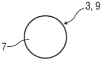
In an exemplary embodiment, the planar proximal surface of the bung is circular and the surface structure comprises four elongate protrusions equally spaced around the proximal surface. The elongated protrusions may be oriented in a radial or tangential direction, for example, with respect to the rounded planar proximal surface.
In another exemplary embodiment, the surface structure comprises two concentric circles. In yet another exemplary embodiment, the surface structure comprises a cross. In yet another exemplary embodiment, the planar proximal surface is circular and the surface structure includes eight small circular protrusions equally spaced around the circular planar proximal surface.
In another exemplary embodiment, the light source and the light sensor are arranged in compartments of the plunger that are optically isolated from each other, thereby preventing light emitted from the light source from directly illuminating the light sensor. Before the plunger contacts the bung, light is emitted from the light source, reflected by the bung and received by the light sensor. Light from the compartment of the light source cannot be reflected into the compartment of the light sensor when in contact with the bung, thus providing a simple means for detecting contact of the plunger with the bung. In this embodiment, the light sensor need not be an imaging sensor. As an alternative, the light sensor may for example be arranged as a light-sensitive resistor.
In an exemplary embodiment, the processing unit for processing the images acquired by the proximity sensor is integrated with the proximity sensor or arranged as an add-on device.
The proximity sensor may be connected to the processing unit and/or another electronic device, such as a control unit of the drug delivery device, by a cable within the plunger of the combination.
In an exemplary embodiment, the distal end of the plunger is substantially flat. In another exemplary embodiment, the distal end of the plunger is arranged as a lens of the proximity sensor. This may simplify the optical elements and manufacturing and thus reduce costs.
The combination may be part of a drug delivery device comprising a cartridge having a bung, a plunger for displacing the bung, an electromechanical driver for displacing the plunger and a combination according to the invention for detecting the position of the plunger relative to the bung.
A control unit may be arranged in the drug delivery device for causing the electromechanical driver to advance the plunger towards the bung and to stop the electromechanical driver in case the proximity sensor detects a bung image indicating contact with the plunger, different from an image before the bung was in contact with the plunger.
This allows the drug delivery device to determine the position of the bung relative to the plunger so as to be able to automatically position the plunger in a position where priming can be performed prior to injection.
Further scope of applicability of the present invention will become apparent from the detailed description given hereinafter. It should be understood, however, that the detailed description and specific examples, while indicating preferred embodiments of the invention, are given by way of illustration only, since various changes and modifications within the spirit and scope of the invention will become apparent to those skilled in the art from this detailed description.
In particular, the invention relates to the following:
1. a combination for detecting the position of a plunger (4) relative to a bung (3) in a medicament cartridge (1), the combination comprising: a proximity sensor (5) positioned close to a distal end (6) of the plunger (4) facing the bung (3) and aligned to receive light reflected by the bung (3), characterized in that the proximity sensor (5) is arranged as an imaging sensor positioned close to the distal end (6) of the plunger (4) facing the bung (3) and aligned to image the bung (3), wherein the bung (3) comprises a flexible material and has a substantially flat proximal face (7), wherein the resilient surface structure (8) protrudes from the flat proximal face (7) and is adapted to deform upon contacting the plunger (4).
2. The combination according to item 1, wherein the proximity sensor (5) comprises a light source (5.1) and a light sensor (5.2).
3. The combination according to claim 2, wherein the proximity sensor (5) comprises a lens.
4. A combination according to any of claims 1 to 3, wherein the flat proximal face (7) is circular, and wherein the surface structure (8) comprises four elongated protrusions equally spaced around the flat proximal face (7).
5. The combination according to item 4, wherein the elongated protrusions are oriented in a radial direction or in a tangential direction with respect to the rounded flat proximal face (7).
6. The combination according to claim 1, wherein the surface structure (8) comprises two concentric circles or crosses or eight small circular protrusions equally spaced around the circular flat proximal surface (7).
7. The combination according to item 2, wherein the light source (5.1) and the light sensor (5.2) are arranged in compartments (4.1, 4.2) optically isolated from each other within the plunger (4) such that light originating from the light source (5.1) is prevented from directly illuminating the light sensor (5.2).
8. The combination according to any one of the preceding claims, wherein a processing unit for processing the images acquired by the proximity sensor (5) is integrated with the proximity sensor (5).
9. The combination according to any one of claims 1 to 7, wherein a processing unit for processing images acquired by the proximity sensor (5) is arranged as an add-on.
10. A combination according to any of claims 8 or 9, wherein the proximity sensor (5) is connected to the processing unit and/or another electronic device by means of a cable (10) arranged within the plunger (4).
11. A combination according to any preceding claim, wherein the distal end (6) of the plunger (4) is substantially flat.
12. A combination according to any of claims 1 to 10, wherein the distal end (6) of the plunger (4) is arranged as a lens of the proximity sensor (5).
13. A drug delivery device comprising a cartridge (1) having a bung (3), a plunger (4) for displacing the bung (3), an electromechanical driver for displacing the plunger (4) and a combination according to any of the preceding claims for detecting the position of the plunger (4) relative to the bung (3).
14. A drug delivery device according to claim 13, wherein the control unit is arranged to cause the electromechanical drive means to advance the plunger (4) towards the bung (3), and to stop the electromechanical drive in case the proximity sensor (5) detects an image (9) of the bung (3) indicative of contact with the plunger (4) that is different from the image (9) before the bung (3) contacts the plunger (4).
Drawings
The present invention will become more fully understood from the detailed description given herein below and the accompanying drawings which are given by way of illustration only, and thus are not limitative of the present invention, and wherein:
figure 1 is a schematic longitudinal detail section of an exemplary embodiment of a cartridge with a combination for detecting the position of a plunger,
figure 2 is a schematic perspective view of an exemplary embodiment of a bung,
figure 3 is an exemplary embodiment of a flat proximal side image of the bung acquired by a proximity sensor before the plunger contacts the bung,
figure 4 is an exemplary embodiment of a flat proximal side image of a bung obtained by a proximity sensor when the plunger is in contact with the bung,
figure 5 is an image of a flat proximal side of a bung having an alternative surface structure,
figure 6 is an image of a flat proximal side of a bung having an alternative surface structure,
figure 7 is an image of a flat proximal side of a bung having an alternative surface structure,
FIG. 8 is a flat proximal side image of a bung having an alternative surface structure, an
Fig. 9 is a schematic longitudinal detail section of another exemplary embodiment of a cartridge with a combination for detecting the position of a plunger.
In the drawings, like reference numerals are used to designate corresponding parts.
Detailed Description
Fig. 1 is a schematic longitudinal detail section of an exemplary embodiment of a cartridge 1 or syringe with a septum 2 or discharge nozzle at the distal end and a bung 3 or stopper arrangement near the proximal end within the cartridge 1. The plunger 4 is arranged to displace the bung 3 within the cartridge 1 in order to dispense the medicament contained within the cartridge 1.
A proximity sensor 5 arranged as an imaging sensor is arranged within the plunger 4. The proximity sensor 5 may be of any type suitable for imaging, but preferably may be of a type comprising a light source, a light sensor, a lens and a processing unit. Proximity sensor 5 is positioned proximate to a flat transparent distal end 6 of plunger 4 facing bung 3 and aligned to image bung 3.
Fig. 2 is a perspective schematic view of an exemplary embodiment of a bung 3. In this embodiment, the bung 3 is constructed of or comprises a flexible material and has a substantially flat proximal face 7, wherein the surface structures 8 protrude from the flat proximal face 7. In the illustrated embodiment, the surface structure 8 comprises four small elongated protrusions ("pips") equally spaced around the circular planar proximal face 7 and oriented in a radial direction. The surface structure 8 is arranged to deform when contacting the plunger 4. Thus, the proximity sensor 5 will detect a different image depending on whether the plunger 4 contacts the bung 3 or not.
Fig. 3 is an exemplary embodiment of an image 9 acquired by the proximity sensor 5 before the plunger 4 contacts the bung 3. No surface structure 8 was detected.
Fig. 4 is an exemplary embodiment of an image 9 acquired by the proximity sensor 5 when the plunger 4 contacts the bung 3. The surface structure 8 is detected.
Fig. 5-8 are alternative exemplary embodiments of images 9 of the flat proximal face 7 of the bung 3 with surface structures 8. In the embodiment of fig. 5, the surface structure 8 comprises two concentric circles. In the embodiment of fig. 6, the surface structure 8 comprises a cross. In the embodiment of fig. 7, the surface structure comprises four small elongated protrusions equally spaced around the circular flat proximal face 7 and arranged tangentially. In the embodiment of fig. 8, the surface structure comprises eight small circular protrusions surrounding the circular flat proximal face 7 at equal intervals.
The processing unit may be integrated with the proximity sensor 5 or arranged as an add-on device. The proximity sensor 5 may be connected to a processing unit and/or other electronics via a cable 10 disposed within the plunger 4.
The cartridge 1 and the plunger 4 may be part of a drug delivery device (not shown). The drug delivery device may comprise a body adapted to receive the cartridge 1. A hypodermic needle may be attached to the cartridge 1, preferably the needle having two tips, one for piercing the injection site and the other for piercing a septum 2 on the cartridge 1 for establishing fluid communication between the cartridge 1 and the needle. The drug delivery device may further comprise at least one electrical unit or electronic device (not shown), such as a control unit and/or a human-machine interface, for communicating information to the user and for allowing the user to operate the drug delivery device and an electromechanical driver (not shown) for inserting the needle into an injection site, e.g. the skin of a patient, and/or dispensing the drug from the cartridge 1 through the needle, and/or retracting the needle after an injection. The electromechanical driver may comprise a motor driven gearbox that drives a simple drive screw or a telescopic drive screw.
In order to properly position the plunger 4 at the plunger 4 before dispensing the medicament, the plunger 4 is driven towards the bung 3, wherein the proximity sensor 5 is actively imaged. The image 9 from the proximity sensor 5 is processed to determine the first occurrence of the protruding surface structure 8 of the bung 3 in contact with the plunger 4. Once this condition is satisfied, the plunger 4 is stopped.
In an exemplary embodiment, the transparent distal end 6 of the plunger 4 may not be flat, but rather is arranged as a lens of the proximity sensor 5. This may simplify the optical elements and manufacturing and thus reduce costs.
Fig. 9 is a schematic longitudinal detail section of an exemplary embodiment of a cartridge 1 or syringe with a septum 2 or discharge nozzle at the distal end and a bung 3 or stopper arranged inside the cartridge 1 near the proximal end. The plunger 4 is arranged to displace the bung 3 within the cartridge 1 in order to dispense the medicament contained within the cartridge 1.
A proximity sensor 5 comprising a light source 5.1 (e.g. a light emitting diode) and a light sensor 5.2 (e.g. a photo resistor) is arranged within the plunger 4.
The light source 5.1 and the light sensor 5.2 are arranged in compartments 4.1, 4.2 optically isolated from each other within the plunger 4 such that light emitted from the light source 5.1 cannot directly illuminate the light sensor 5.2.
The compartments 4.1, 4.2 are open at the distal end of the plunger 4 facing the bung 3.
The processing unit may be integrated with the proximity sensor 5 or arranged as an add-on device. The proximity sensor 5 may be connected to a processing unit and/or other electronics via a cable 10 disposed within the plunger 4.
Before contacting the bung 3, light emitted from the light source 5.1 is reflected by the bung 3 and detected by the light sensor 5.2. At the moment the plunger contacts the surface of the bung 3, the two compartments are covered and optically isolated from each other. At this point, no light is received at the light sensor 5.2. This enables contact between the plunger 4 and the bung 3 to be detected, for example by means of the processing unit. Thus, when the light detected by the light sensor 5.2 is below a threshold value, the processing unit judges that contact between the plunger 4 and the bung 3 has occurred, for example by detecting that the level of the electrical signal generated by the light sensor 5.2 is below a predetermined threshold value.
To properly position the plunger 4 at the plunger 4 prior to dispensing the medicament, the plunger 4 is driven towards the bung 3 while the proximity sensor 5 receives light. The response from the proximity sensor 5 is processed to determine that the bung 3 is in first contact with the plunger 4. Once this condition is satisfied, the plunger 4 is stopped.
The term "drug" or "medicament" as used herein means a pharmaceutical formulation containing at least one pharmaceutically active compound,
wherein in one embodiment the pharmaceutically active compound has a molecular weight of up to 1500Da and/or is a peptide, protein, polysaccharide, vaccine, DNA, RNA, enzyme, antibody or fragment thereof, hormone or oligonucleotide, or is a mixture of the above pharmaceutically active compounds,
wherein in a further embodiment the pharmaceutically active compound is useful for the treatment and/or prevention of diabetes mellitus or complications associated with diabetes mellitus, such as diabetic retinopathy (diabetic retinopathy), thromboembolic disorders (thromboembolism disorders) such as deep vein or pulmonary thromboembolism, Acute Coronary Syndrome (ACS), angina pectoris, myocardial infarction, cancer, macular degeneration (macular degeneration), inflammation, hay fever, atherosclerosis and/or rheumatoid arthritis,
wherein in a further embodiment the pharmaceutically active compound comprises at least one peptide for the treatment and/or prevention of diabetes or complications associated with diabetes, such as diabetic retinopathy,
wherein in a further embodiment the pharmaceutically active compound comprises at least one human insulin or human insulin analogue or derivative, glucagon-like peptide (GLP-1) or analogue or derivative thereof, or exendin-3 (exedin-3) or exendin-4 (exendin-4) or analogue or derivative of exendin-3 or exendin-4.
Insulin analogs such as Gly (a21), Arg (B31), Arg (B32) human insulin; lys (B3), Glu (B29) human insulin; lys (B28), Pro (B29) human insulin; asp (B28) human insulin; human insulin wherein proline at position B28 is replaced by Asp, Lys, Leu, Val or Ala and wherein lysine at position B29 is replaced by Pro; ala (B26) human insulin; des (B28-B30) human insulin; des (B27) human insulin; and Des (B30) human insulin.
Insulin derivatives such as B29-N-myristoyl-des (B30) human insulin; B29-N-palmitoyl-des (B30) human insulin; B29-N-myristoyl human insulin; B29-N-palmitoyl human insulin; B28-N-myristoyl LysB28ProB29 human insulin; B28-N-palmitoyl-LysB 28ProB29 human insulin; B30-N-myristoyl-ThrB 29LysB30 human insulin; B30-N-palmitoyl-ThrB 29LysB30 human insulin; B29-N- (N-palmitoyl-glutamyl) -des (B30) human insulin; B29-N- (N-lithochol- γ -glutamyl) -des (B30) human insulin; B29-N- (. omega. -carboxyheptadecanoyl) -des (B30) human insulin and B29-N- (. omega. -carboxyheptadecanoyl) human insulin.
Exendin-4 means for example exendin-4 (1-39), which is a peptide having the following sequence: HHis-Gly-Glu-Gly-Thr-Phe-Thr-Ser-Asp-Leu-Ser-Lys-Gln-Met-Glu-Glu-Ala-Val-Arg-Leu-Phe-Ile-Glu-Trp-Leu-Lys-Asn-Gly-Gly-Pro-Ser-Ser-Gly-Ala-Pro-Pro-Pro-Ser-NH2。
Exendin-4 derivatives are for example selected from the following list of compounds:
h- (Lys)4-des Pro36, des Pro37 Exendin-4 (1-39) -NH2,
h- (Lys)5-des Pro36, des Pro37 Exendin-4 (1-39) -NH2,
des Pro36[ Asp28] Exendin-4 (1-39),
des Pro36[ IsoAsp28] Exendin-4 (1-39),
des Pro36[ Met (O)14, Asp28] Exendin-4 (1-39),
des Pro36[ Met (O)14, IsoAsp28] Exendin-4 (1-39),
des Pro36[ Trp (O2)25, Asp28] Exendin-4 (1-39),
des Pro36[ Trp (O2)25, IsoAsp28] Exendin-4 (1-39),
des Pro36[ Met (O)14Trp (O2)25, Asp28] Exendin-4 (1-39),
des Pro36[ Met (O)14Trp (O2)25, IsoAsp28] Exendin-4 (1-39); or
des Pro36[ Asp28] Exendin-4 (1-39),
des Pro36[ IsoAsp28] Exendin-4 (1-39),
des Pro36[ Met (O)14, Asp28] Exendin-4 (1-39),
des Pro36[ Met (O)14, IsoAsp28] Exendin-4 (1-39),
des Pro36[ Trp (O2)25, Asp28] Exendin-4 (1-39),
des Pro36[ Trp (O2)25, IsoAsp28] Exendin-4 (1-39),
des Pro36[ Met (O)14Trp (O2)25, Asp28] Exendin-4 (1-39),
des Pro36[ Met (O)14Trp (O2)25, IsoAsp28] Exendin-4 (1-39),
wherein the-Lys 6-NH2 group may be bound to the C-terminus of an exendin-4 derivative;
or an exendin-4 derivative of the sequence
H- (Lys)6-des Pro36[ Asp28] exendin-4 (1-39) -Lys6-NH2,
des Asp28 Pro36, Pro37, Pro38 Exendin-4 (1-39) -NH2,
h- (Lys)6-des Pro36, Pro38[ Asp28] exendin-4 (1-39) -NH2,
H-Asn- (Glu)5des Pro36, Pro37, Pro38[ Asp28] exendin-4 (1-39) -NH2,
des Pro36, Pro37, Pro38[ Asp28] Exendin-4 (1-39) - (Lys)6-NH2,
h- (Lys)6-des Pro36, Pro37, Pro38[ Asp28] exendin-4 (1-39) - (Lys)6-NH2,
H-Asn- (Glu)5-des Pro36, Pro37, Pro38[ Asp28] Exendin-4 (1-39) - (Lys)6-NH2,
h- (Lys)6-des Pro36[ Trp (O2)25, Asp28] exendin-4 (1-39) -Lys6-NH2,
h-des Asp28 Pro36, Pro37, Pro38[ Trp (O2)25] Exendin-4 (1-39) -NH2,
h- (Lys)6-des Pro36, Pro37, Pro38[ Trp (O2)25, Asp28] exendin-4 (1-39) -NH2,
H-Asn- (Glu)5-des Pro36, Pro37, Pro38[ Trp (O2)25, Asp28] Exendin-4 (1-39) -NH2,
des Pro36, Pro37, Pro38[ Trp (O2)25, Asp28] Exendin-4 (1-39) - (Lys)6-NH2,
h- (Lys)6-des Pro36, Pro37, Pro38[ Trp (O2)25, Asp28] exendin-4 (1-39) - (Lys)6-NH2,
H-Asn- (Glu)5-des Pro36, Pro37, Pro38[ Trp (O2)25, Asp28] Exendin-4 (1-39) - (Lys)6-NH2,
h- (Lys)6-des Pro36[ Met (O)14, Asp28] exendin-4 (1-39) -Lys6-NH2,
des Met (O)14Asp28 Pro36, Pro37, Pro38 Exendin-4 (1-39) -NH2,
h- (Lys)6-desPro36, Pro37, Pro38[ Met (O)14, Asp28] exendin-4 (1-39) -NH2,
H-Asn- (Glu)5-des Pro36, Pro37, Pro38[ Met (O)14, Asp28] Exendin-4 (1-39) -NH2,
des Pro36, Pro37, Pro38[ Met (O)14, Asp28] Exendin-4 (1-39) - (Lys)6-NH2,
h- (Lys)6-des Pro36, Pro37, Pro38[ Met (O)14, Asp28] exendin-4 (1-39) - (Lys)6-NH2,
H-Asn- (Glu)5des Pro36, Pro37, Pro38[ Met (O)14, Asp28] Exendin-4 (1-39) - (Lys)6-NH2,
H-Lys6-des Pro36[ Met (O)14, Trp (O2)25, Asp28] exendin-4 (1-39) -Lys6-NH2,
h-des Asp28 Pro36, Pro37, Pro38[ Met (O)14, Trp (O2)25] exendin-4 (1-39) -NH2,
h- (Lys)6-des Pro36, Pro37, Pro38[ Met (O)14, Asp28] exendin-4 (1-39) -NH2,
H-Asn- (Glu)5-des Pro36, Pro37, Pro38[ Met (O)14, Trp (O2)25, Asp28] Exendin-4 (1-39) -NH2,
des Pro36, Pro37, Pro38[ Met (O)14, Trp (O2)25, Asp28] Exendin-4 (1-39) - (Lys)6-NH2,
h- (Lys)6-des Pro36, Pro37, Pro38[ Met (O)14, Trp (O2)25, Asp28] Exendin-4 (S1-39) - (Lys)6-NH2,
H-Asn- (Glu)5-des Pro36, Pro37, Pro38[ Met (O)14, Trp (O2)25, Asp28] Exendin-4 (1-39) - (Lys)6-NH 2;
or a pharmaceutically acceptable salt or solvate of any of the foregoing exendin-4 derivatives.
Hormones such as the pituitary hormones (hypophysics hormons) or hypothalamic hormones (hypothalmus hormons) or regulatory active peptides (regulatory active peptides) listed in Rote list, ed.2008, chapter 50 and their antagonists, such as gonadotropins (Follitropin), luteinizing hormone (Lutropin), chorionic gonadotropins (chondronadotropin), menopause gonadotropins (menotropins), somatropins (Somatropin), desmopressins (Desmopressin), terlipressins (terlipressins), gonadorelins (Gonadorelin), Triptorelin (Triptorelin), Leuprorelin (Leuprorelin), brerelin (Buserelin), Nafarelin (Nafarelin), sertralin (gororelin).
Polysaccharides such as glycosaminoglycans (glycosaminoglycans), hyaluronic acid (hyaluronic acid), heparin, low molecular weight heparin or ultra-low molecular weight heparin or derivatives thereof, or sulphated, e.g. polysulfated, forms of the aforementioned polysaccharides, and/or pharmaceutically acceptable salts thereof. An example of a pharmaceutically acceptable salt of polysulfated low molecular weight heparin is enoxaparin sodium (enoxaparin sodium).
Antibodies are globular plasma proteins (-150 kDa), also known as immunoglobulins, which share a single basic structure. They are glycoproteins because they have sugar chains added to amino acid residues. The basic functional unit of each antibody is an immunoglobulin (Ig) monomer (containing only one Ig unit); the secreted antibody may also be a dimer with two Ig units, such as IgA, a tetramer with four Ig units, such as IgM for teleost fish (teleost fish), or a pentamer with five Ig units, such as IgM for mammals.
Ig monomers are "Y" shaped molecules, which are composed of four polypeptide chains; two identical heavy chains and two identical light chains, which are linked by disulfide bonds between cysteine residues. Each heavy chain is about 440 amino acids long; each light chain is about 220 amino acids long. Each heavy and light chain contains intrachain disulfide bonds that stabilize their folding. Each chain is composed of domains called Ig domains. These domains contain about 70-110 amino acids and are classified into different categories (e.g., variable or V, constant or C) according to their size and function. They have a characteristic immunoglobulin fold in which two beta sheets create a "sandwich" shape that is held together by the interaction between conserved cysteines and other charged amino acids.
There are five types of mammalian Ig heavy chains, denoted as α, δ, ε, γ, and μ. The type of heavy chain present determines the isotype of the antibody; these chains can be found in IgA, IgD, IgE, IgG, and IgM antibodies, respectively.
The size and composition of the different heavy chains are different; alpha and gamma contain about 450 amino acids, delta contains about 500 amino acids, and mu and epsilon have about 550 amino acids. Each heavy chain has two regions, a constant region (CH) and a variable region (VH). In one species, the constant region is substantially identical in all antibodies of the same isotype, but is different in antibodies of different isotypes. Heavy chains γ, α, and δ have constant regions comprising three tandem Ig domains, and hinge regions for increased flexibility; heavy chains mu and epsilon have constant regions comprising four immunoglobulin domains. The variable region of the heavy chain is different in antibodies produced by different B cells, but is the same for all antibodies produced by a single B cell or a single B cell clone. The variable region of each heavy chain is approximately 110 amino acids long and contains a single Ig domain.
In mammals, there are two types of immunoglobulin light chains, denoted as λ and κ. The light chain has two contiguous domains: one constant domain (CL) and one variable domain (VL). Light chain lengths range from about 211 to 217 amino acids. Each antibody contains two light chains, which are always identical; only one type of light chain is present per antibody in mammals, either kappa or lambda.
As detailed above, while the general structure of all antibodies is very similar, the unique properties of a given antibody are determined by the variable (V) regions. More specifically, the variable loops, three each on the light chain (VL) and heavy chain (VH), are responsible for binding to the antigen, i.e. antigen specificity. These loops are called Complementarity Determining Regions (CDRs). Since the CDRs from both the VH and VL domains contribute to the antigen-binding site, it is the combination of the heavy and light chains, not the single one, that determines the final antigen specificity.
An "antibody fragment" contains at least one antigen-binding fragment as defined above and exhibits substantially the same function and specificity as the intact antibody from which the antibody fragment is derived. The Ig prototypes were cleaved into three fragments by papain (papain) limited proteolytic digestion. Two identical amino terminal fragments are antigen binding fragments (Fab), each containing one complete L chain and about half of the H chain. The third fragment is a crystallizable fragment (Fc) of similar size but containing the carboxy-terminal half of the two heavy chains and having interchain disulfide bonds. The Fc contains a carbohydrate, a complement binding site, and an FcR binding site. Restriction pepsin (pepsin) digestion produces a single F (ab')2 fragment containing two Fab and hinge regions, which includes an H-H interchain disulfide bond. F (ab')2 is bivalent for antigen binding. The disulfide bond of F (ab ')2 can be cleaved to obtain Fab'. In addition, the variable regions of the heavy and light chains can be fused together to form single chain variable fragments (scfvs).
Pharmaceutically acceptable salts such as acid addition salts and basic salts. Acid addition salts such as the HCl or HBr salt. Basic salts are for example salts with a cation selected from alkali or alkaline earth, such as Na +, or K +, or Ca2+, or the ammonium ion N + (R1) (R2) (R3) (R4), wherein R1 to R4 are independently of each other: hydrogen, optionally substituted C1-C6 alkyl, optionally substituted C2-C6 alkenyl, optionally substituted C6-C10 aryl, or optionally substituted C6-C10 heteroaryl. Further examples of pharmaceutically acceptable salts are described in "Remington's Pharmaceutical Sciences" 17 th edition Alfonso R.Gennaro (eds.), Mark Publishing Company, Easton, Pa., U.S.A.,1985 and Encyclopedia of Pharmaceutical Technology.
Pharmaceutically acceptable solvates such as hydrates.
Those skilled in the art will appreciate that various modifications (additions and/or deletions) may be made to the apparatus components, methods, and/or systems and the embodiments described herein without departing from the full scope and spirit of the invention, which includes such modifications and any and all equivalents thereof.
List of reference numerals
1 cartridge 2 septum
3 cylinder plug 4 plunger
4.1 Compartment 4.2 Compartment
5 proximity sensor 5.1 light source
5.2 light sensor 6 transparent distal end
7 flat proximal surface 8 surface structure
9 image 10 cable
D distal direction P proximal direction
Claims (11)
Applications Claiming Priority (3)
| Application Number | Priority Date | Filing Date | Title |
|---|---|---|---|
| EP13153137.8 | 2013-01-29 | ||
| EP13153137 | 2013-01-29 | ||
| CN201480005945.0A CN104968380B (en) | 2013-01-29 | 2014-01-27 | Assemblies for detecting plunger position |
Related Parent Applications (1)
| Application Number | Title | Priority Date | Filing Date |
|---|---|---|---|
| CN201480005945.0A Division CN104968380B (en) | 2013-01-29 | 2014-01-27 | Assemblies for detecting plunger position |
Publications (2)
| Publication Number | Publication Date |
|---|---|
| CN109099945A CN109099945A (en) | 2018-12-28 |
| CN109099945B true CN109099945B (en) | 2021-11-02 |
Family
ID=47720303
Family Applications (2)
| Application Number | Title | Priority Date | Filing Date |
|---|---|---|---|
| CN201810843299.5A Active CN109099945B (en) | 2013-01-29 | 2014-01-27 | Combination for detecting plunger position |
| CN201480005945.0A Active CN104968380B (en) | 2013-01-29 | 2014-01-27 | Assemblies for detecting plunger position |
Family Applications After (1)
| Application Number | Title | Priority Date | Filing Date |
|---|---|---|---|
| CN201480005945.0A Active CN104968380B (en) | 2013-01-29 | 2014-01-27 | Assemblies for detecting plunger position |
Country Status (6)
| Country | Link |
|---|---|
| US (4) | US9878099B2 (en) |
| EP (1) | EP2950850B1 (en) |
| JP (3) | JP6367829B2 (en) |
| CN (2) | CN109099945B (en) |
| DK (1) | DK2950850T3 (en) |
| WO (1) | WO2014118107A1 (en) |
Families Citing this family (21)
| Publication number | Priority date | Publication date | Assignee | Title |
|---|---|---|---|---|
| DE102014217773A1 (en) * | 2014-09-05 | 2016-03-10 | Vetter Pharma-Fertigung GmbH & Co. KG | Pen |
| EP3085404A1 (en) * | 2015-04-21 | 2016-10-26 | Sanofi-Aventis Deutschland GmbH | Dosing mechanism and drug delivery device |
| WO2017005878A1 (en) * | 2015-07-08 | 2017-01-12 | Sanofi | Drug delivery device with load indicator |
| US10722658B2 (en) | 2016-02-26 | 2020-07-28 | Eli Lilly And Company | Reusable medication delivery device with remaining medication determination capability |
| AU2017237925B2 (en) | 2016-03-25 | 2019-04-04 | Eli Lilly And Company | Determination of a dose set and delivered in a medication delivery device |
| US11266788B2 (en) | 2016-04-19 | 2022-03-08 | Eli Lilly And Company | Determination of a dose in a medication delivery device using two moving arrays with teeth and a sensor |
| JP6718554B2 (en) | 2016-08-12 | 2020-07-08 | イーライ リリー アンド カンパニー | Dose determination in drug delivery devices |
| KR20180032832A (en) * | 2016-09-23 | 2018-04-02 | 최규동 | Insulin Injection Appartus with Opical Sensor |
| WO2018111708A1 (en) | 2016-12-15 | 2018-06-21 | Eli Lilly And Company | Medication delivery device with sensing system |
| WO2018202663A1 (en) * | 2017-05-05 | 2018-11-08 | Sanofi | Cartridge for dosage sensing |
| JP7204688B2 (en) | 2017-06-09 | 2023-01-16 | サノフイ | Electronics for dose sensing |
| US20200230325A1 (en) | 2017-09-30 | 2020-07-23 | Novo Nordisk A/S | Cartridge system for a drug delivery device |
| EP3697477A1 (en) * | 2017-10-19 | 2020-08-26 | Sanofi | A medicament delivery device |
| CN111344031B (en) | 2017-11-14 | 2026-01-06 | 赛诺菲 | Power saving in injection device |
| CN111655311B (en) * | 2017-12-01 | 2022-09-30 | 赛诺菲 | Sensor system |
| FI127724B (en) * | 2017-12-22 | 2019-01-15 | Salecron Oy | Device and method for measuring and recording a dose of medicine in a medicine dosing device |
| EP4241810A3 (en) * | 2017-12-28 | 2023-11-15 | Sanofi | A dosage measurement system |
| US11878146B2 (en) | 2018-05-04 | 2024-01-23 | Sanofi | Measurement probe for an injection device |
| CN114051419A (en) | 2019-07-01 | 2022-02-15 | 赛诺菲 | Wake-up electronics in an injection device |
| US12214173B2 (en) * | 2021-06-08 | 2025-02-04 | Medtronic Minimed, Inc. | Injection pens for medicine administration and tracking |
| KR102838934B1 (en) * | 2022-08-11 | 2025-07-25 | 김대현 | Insulin pump |
Citations (5)
| Publication number | Priority date | Publication date | Assignee | Title |
|---|---|---|---|---|
| CN1245888A (en) * | 1998-08-07 | 2000-03-01 | 株式会社丰田自动织机制作所 | Position detecting device for hydraulic cylinder |
| WO2002083209A1 (en) * | 2001-04-13 | 2002-10-24 | Nipro Diabetes Systems | Drive system for an infusion pump |
| CN101868179A (en) * | 2007-09-21 | 2010-10-20 | 爱德华兹生命科学Iprm公司 | Position detection device and method for detecting at least two positions |
| CN101909673A (en) * | 2007-12-31 | 2010-12-08 | 诺沃-诺迪斯克有限公司 | Electronically monitored injection equipment |
| CN102591453A (en) * | 2010-12-02 | 2012-07-18 | 夏普株式会社 | Proximity sensor and electronic device |
Family Cites Families (84)
| Publication number | Priority date | Publication date | Assignee | Title |
|---|---|---|---|---|
| US533575A (en) | 1895-02-05 | wilkens | ||
| US5226895A (en) | 1989-06-05 | 1993-07-13 | Eli Lilly And Company | Multiple dose injection pen |
| GB9007113D0 (en) | 1990-03-29 | 1990-05-30 | Sams Bernard | Dispensing device |
| US5106379A (en) * | 1991-04-09 | 1992-04-21 | Leap E Jack | Syringe shielding assembly |
| JPH05208157A (en) | 1991-07-01 | 1993-08-20 | Tenryu Technic:Kk | Dispenser |
| EP0525525B1 (en) | 1991-07-24 | 1995-05-03 | Medico Development Investment Company | Injector |
| DK175491D0 (en) | 1991-10-18 | 1991-10-18 | Novo Nordisk As | APPARATUS |
| US5279585A (en) | 1992-02-04 | 1994-01-18 | Becton, Dickinson And Company | Medication delivery pen having improved dose delivery features |
| US5320609A (en) | 1992-12-07 | 1994-06-14 | Habley Medical Technology Corporation | Automatic pharmaceutical dispensing syringe |
| US5383865A (en) | 1993-03-15 | 1995-01-24 | Eli Lilly And Company | Medication dispensing device |
| ZA941881B (en) | 1993-04-02 | 1995-09-18 | Lilly Co Eli | Manifold medication injection apparatus and method |
| US5433712A (en) * | 1993-06-10 | 1995-07-18 | Donald E. Stiles | Self-sheathing hypodermic syringe |
| US5792117A (en) * | 1994-07-22 | 1998-08-11 | Raya Systems, Inc. | Apparatus for optically determining and electronically recording injection doses in syringes |
| US5582598A (en) | 1994-09-19 | 1996-12-10 | Becton Dickinson And Company | Medication delivery pen with variable increment dose scale |
| CA2213682C (en) | 1995-03-07 | 2009-10-06 | Eli Lilly And Company | Recyclable medication dispensing device |
| US5674204A (en) | 1995-09-19 | 1997-10-07 | Becton Dickinson And Company | Medication delivery pen cap actuated dose delivery clutch |
| US5688251A (en) | 1995-09-19 | 1997-11-18 | Becton Dickinson And Company | Cartridge loading and priming mechanism for a pen injector |
| US5607399A (en) * | 1995-09-22 | 1997-03-04 | Becton, Dickinson And Company | Backstop device for a flangeless syringe |
| US5927957A (en) * | 1996-06-19 | 1999-07-27 | Kennedy; Craig A. | Plunger device and method of making and using the same thereof |
| DE19652708C2 (en) * | 1996-12-18 | 1999-08-12 | Schott Glas | Process for producing a filled plastic syringe body for medical purposes |
| EP0916353B1 (en) * | 1997-01-10 | 2004-09-01 | Japan Servo Co. Ltd. | Liquid transportation apparatus |
| DE19730999C1 (en) | 1997-07-18 | 1998-12-10 | Disetronic Licensing Ag | Injection pen dosing selected volume of fluid, especially insulin |
| US5921966A (en) | 1997-08-11 | 1999-07-13 | Becton Dickinson And Company | Medication delivery pen having an improved clutch assembly |
| KR100574630B1 (en) | 1998-01-30 | 2006-04-27 | 노보 노르디스크 에이/에스 | Injection syringe |
| US5961495A (en) | 1998-02-20 | 1999-10-05 | Becton, Dickinson And Company | Medication delivery pen having a priming mechanism |
| US6221053B1 (en) | 1998-02-20 | 2001-04-24 | Becton, Dickinson And Company | Multi-featured medication delivery pen |
| US6248095B1 (en) | 1998-02-23 | 2001-06-19 | Becton, Dickinson And Company | Low-cost medication delivery pen |
| GB9807020D0 (en) * | 1998-04-02 | 1998-06-03 | Bamford Excavators Ltd | A method of marking a mechanical element, an encoding scheme, a reading means for said marking and an apparatus for determining the position of said element |
| US6645177B1 (en) * | 1999-02-09 | 2003-11-11 | Alaris Medical Systems, Inc. | Directly engaged syringe driver system |
| US6027481A (en) * | 1999-03-08 | 2000-02-22 | Becton Dickinson And Company | Prefillable syringe |
| JP2000300668A (en) * | 1999-04-26 | 2000-10-31 | Takeshi Takachi | Mechanical lock mechanism and injector head using the mechanism |
| JP4290366B2 (en) | 1999-08-05 | 2009-07-01 | ベクトン・ディキンソン・アンド・カンパニー | Drug delivery pen |
| GB0007071D0 (en) | 2000-03-24 | 2000-05-17 | Sams Bernard | One-way clutch mechanisms and injector devices |
| US6663602B2 (en) | 2000-06-16 | 2003-12-16 | Novo Nordisk A/S | Injection device |
| US20020000290A1 (en) | 2000-06-29 | 2002-01-03 | Crump Larry Scott | Curing of a gel coat on a mold |
| AUPQ867900A0 (en) * | 2000-07-10 | 2000-08-03 | Medrad, Inc. | Medical injector system |
| US7462166B2 (en) * | 2000-12-11 | 2008-12-09 | Medrad, Inc. | Encoding and sensing of syringe information |
| US6899699B2 (en) | 2001-01-05 | 2005-05-31 | Novo Nordisk A/S | Automatic injection device with reset feature |
| US7018363B2 (en) * | 2001-01-18 | 2006-03-28 | Medrad, Inc. | Encoding and sensing of syringe information |
| DE60218452T2 (en) | 2001-05-16 | 2007-11-15 | Eli Lilly And Co., Indianapolis | MEDICAMENT INJECTION DEVICE WITH RESERVATION OF SIMILAR DRIVE ARRANGEMENT |
| GB0129173D0 (en) * | 2001-12-06 | 2002-01-23 | Dca Design Int Ltd | Improvements in and relating to a medicament cartridge |
| CA2492983C (en) | 2002-07-24 | 2010-07-20 | Deka Products Limited Partnership | Optical displacement sensor for infusion devices |
| AU2003295963B2 (en) * | 2002-11-25 | 2009-09-03 | Boston Scientific Limited | Injection device for treating mammalian body |
| US6877530B2 (en) * | 2002-12-03 | 2005-04-12 | Forhealth Technologies, Inc. | Automated means for withdrawing a syringe plunger |
| JP4229688B2 (en) | 2002-12-17 | 2009-02-25 | 株式会社根本杏林堂 | Leak detection device |
| GB0304823D0 (en) | 2003-03-03 | 2003-04-09 | Dca Internat Ltd | Improvements in and relating to a pen-type injector |
| US7351223B2 (en) * | 2003-05-05 | 2008-04-01 | Physicians Industries, Inc. | Infusion syringe with integrated pressure transducer |
| US7419478B1 (en) * | 2003-06-25 | 2008-09-02 | Medrad, Inc. | Front-loading syringe for medical injector having a flexible syringe retaining ring |
| DE10330984B4 (en) * | 2003-07-09 | 2009-12-10 | Tecpharma Licensing Ag | Injection device with position sensor |
| US20050015019A1 (en) * | 2003-07-18 | 2005-01-20 | Yamatake Corporation | Sampling syringe unit, sampling device and sampling method for sampling blood or body fluid |
| EP1660158B1 (en) * | 2003-07-31 | 2008-12-24 | Sid Technologies Llc | Syringe with automatically triggered safety sleeve |
| US7056301B2 (en) * | 2003-09-05 | 2006-06-06 | Jung-O Liu | Syringe |
| EP1735032A1 (en) | 2004-04-08 | 2006-12-27 | Eli Lilly And Company | Pharmaceutical cartridge piston with rigid core |
| DE102004063644A1 (en) | 2004-12-31 | 2006-07-20 | Tecpharma Licensing Ag | Device for the dosed administration of a fluid product with torsion spring drive |
| US20060229567A1 (en) * | 2005-03-04 | 2006-10-12 | Wright Clifford A | Suction tip holster insert |
| WO2006124819A1 (en) | 2005-05-16 | 2006-11-23 | Mallinckrodt Inc. | Multi-stage syringe and methods of using the same |
| CA2888263A1 (en) * | 2005-11-29 | 2007-06-07 | Cornelis Kees Klein | Syringe for use in spectroscopy |
| FR2899482A1 (en) | 2006-04-11 | 2007-10-12 | Becton Dickinson France Soc Pa | Automatic medicament/product injection device for patient, has safety shield coupled to housing, and provided in active state at end of needle insertion step before which product/medicament injection step is not started |
| GB2451379B (en) * | 2006-05-02 | 2010-12-29 | Kathy Mcewen | System and method of providing bandwith on demand |
| WO2007136659A2 (en) * | 2006-05-16 | 2007-11-29 | Timothy Ackerman | Prefilled single use auto-disabling safety syringe |
| DE102006047537B4 (en) * | 2006-10-07 | 2024-05-16 | Sanofi-Aventis Deutschland Gmbh | Method and device for determining the position of a stopper of an ampoule for a drug in a medical device and their use, a corresponding medical device and manufacture of a medical device |
| JP2010538797A (en) * | 2007-09-17 | 2010-12-16 | サンダー,サティシュ | High precision infusion pump controller |
| ES2652537T3 (en) | 2007-09-21 | 2018-02-05 | Imaxeon Pty Ltd | Releasable connection mechanism |
| US20090137949A1 (en) * | 2007-11-26 | 2009-05-28 | Bioject Inc. | Needle-free injection device with nozzle auto-disable |
| WO2009125582A1 (en) * | 2008-04-10 | 2009-10-15 | パナソニック株式会社 | Medication administering device |
| US8647309B2 (en) | 2008-05-02 | 2014-02-11 | Sanofi-Aventis Deutschland Gmbh | Medication delivery device |
| DE102008035835B4 (en) * | 2008-08-02 | 2015-02-19 | Walter Pobitschka | Method and device for transferring a substance between closed systems |
| US7905860B2 (en) * | 2008-09-05 | 2011-03-15 | Elixir Corp. | Plunger disc loading mechanism for syringe pump |
| JP5283516B2 (en) | 2009-01-09 | 2013-09-04 | シャープ株式会社 | Optical device, object detection method using the optical device, and electronic apparatus |
| JP2010199706A (en) * | 2009-02-23 | 2010-09-09 | Sharp Corp | Proximity sensor with illuminance detection function and electronic device |
| WO2010112376A1 (en) * | 2009-03-31 | 2010-10-07 | Sanofi-Aventis Deutschland Gmbh | Improvements in and relating to medicament delivery devices |
| US20100262002A1 (en) * | 2009-04-09 | 2010-10-14 | Mallinckrodt Inc. | Syringe Identification System |
| US8773660B2 (en) * | 2009-09-18 | 2014-07-08 | Sanofi—Aventis Deutschland GmbH | Arrangement for determining a longitudinal position of a stopper |
| US9095650B2 (en) * | 2009-10-06 | 2015-08-04 | Flex Partners, Inc. | Precision fluid delivery systems |
| BR112012014467B1 (en) | 2009-12-18 | 2020-11-03 | Sanofi-Aventis Deutschland Gmbh | drug delivery device |
| WO2011099551A1 (en) * | 2010-02-12 | 2011-08-18 | 株式会社根本杏林堂 | Medical fluid administration device, and medical fluid administration system |
| WO2011113806A1 (en) * | 2010-03-16 | 2011-09-22 | Sanofi-Aventis Deutschland Gmbh | Controlling a motor of an injection device |
| US9155833B2 (en) * | 2011-03-04 | 2015-10-13 | Becton, Dickinson And Company | Systems and methods for monitoring the use of medications |
| US9289562B2 (en) * | 2011-04-18 | 2016-03-22 | THORNE CONSULTING and INTELETUAL PROPERTY, LLC | Pressure actuated valve for multi-chamber syringe applications |
| WO2013054165A1 (en) * | 2011-10-11 | 2013-04-18 | Hospitech Respiration Ltd. | Pressure regulating syringe and method therefor |
| DE102012204394A1 (en) * | 2012-03-20 | 2013-09-26 | B. Braun Melsungen Ag | Injection device for administering a liquid |
| EP2830680A1 (en) * | 2012-03-27 | 2015-02-04 | Novo Nordisk A/S | Drug delivery device with piston proximity sensing |
| US9022968B2 (en) * | 2013-01-08 | 2015-05-05 | University Of South Florida | Auto-regulation system for intraocular pressure |
| US9623191B2 (en) * | 2013-03-01 | 2017-04-18 | Bayer Healthcare Llc | Information sensing syringe |
-
2014
- 2014-01-27 CN CN201810843299.5A patent/CN109099945B/en active Active
- 2014-01-27 US US14/761,769 patent/US9878099B2/en active Active
- 2014-01-27 JP JP2015554167A patent/JP6367829B2/en active Active
- 2014-01-27 DK DK14703795.6T patent/DK2950850T3/en active
- 2014-01-27 WO PCT/EP2014/051470 patent/WO2014118107A1/en not_active Ceased
- 2014-01-27 CN CN201480005945.0A patent/CN104968380B/en active Active
- 2014-01-27 EP EP14703795.6A patent/EP2950850B1/en active Active
-
2018
- 2018-01-23 US US15/877,920 patent/US10561790B2/en active Active
- 2018-07-04 JP JP2018127441A patent/JP6711865B2/en active Active
-
2019
- 2019-12-26 US US16/727,003 patent/US11116906B2/en active Active
-
2020
- 2020-05-26 JP JP2020091246A patent/JP7100679B2/en active Active
-
2021
- 2021-08-11 US US17/400,019 patent/US11786657B2/en active Active
Patent Citations (5)
| Publication number | Priority date | Publication date | Assignee | Title |
|---|---|---|---|---|
| CN1245888A (en) * | 1998-08-07 | 2000-03-01 | 株式会社丰田自动织机制作所 | Position detecting device for hydraulic cylinder |
| WO2002083209A1 (en) * | 2001-04-13 | 2002-10-24 | Nipro Diabetes Systems | Drive system for an infusion pump |
| CN101868179A (en) * | 2007-09-21 | 2010-10-20 | 爱德华兹生命科学Iprm公司 | Position detection device and method for detecting at least two positions |
| CN101909673A (en) * | 2007-12-31 | 2010-12-08 | 诺沃-诺迪斯克有限公司 | Electronically monitored injection equipment |
| CN102591453A (en) * | 2010-12-02 | 2012-07-18 | 夏普株式会社 | Proximity sensor and electronic device |
Also Published As
| Publication number | Publication date |
|---|---|
| US20150320934A1 (en) | 2015-11-12 |
| US20200155762A1 (en) | 2020-05-21 |
| US20180147350A1 (en) | 2018-05-31 |
| JP2016504129A (en) | 2016-02-12 |
| EP2950850B1 (en) | 2016-10-26 |
| DK2950850T3 (en) | 2017-02-06 |
| US20210369964A1 (en) | 2021-12-02 |
| JP7100679B2 (en) | 2022-07-13 |
| CN109099945A (en) | 2018-12-28 |
| WO2014118107A1 (en) | 2014-08-07 |
| CN104968380A (en) | 2015-10-07 |
| HK1211518A1 (en) | 2016-05-27 |
| JP6367829B2 (en) | 2018-08-01 |
| US11786657B2 (en) | 2023-10-17 |
| US9878099B2 (en) | 2018-01-30 |
| JP6711865B2 (en) | 2020-06-17 |
| CN104968380B (en) | 2018-08-21 |
| EP2950850A1 (en) | 2015-12-09 |
| JP2018171486A (en) | 2018-11-08 |
| JP2020127836A (en) | 2020-08-27 |
| US11116906B2 (en) | 2021-09-14 |
| US10561790B2 (en) | 2020-02-18 |
Similar Documents
| Publication | Publication Date | Title |
|---|---|---|
| CN109099945B (en) | Combination for detecting plunger position | |
| CN108295342B (en) | drug delivery device | |
| CN105579083B (en) | auto injector | |
| US11224695B2 (en) | Drug delivery device | |
| CN104703642B (en) | Injection device | |
| CN105517598B (en) | auto injector | |
| US20240350731A1 (en) | Medicament Delivery Device and Actuation Mechanism for a Drug Delivery Device | |
| CN104379195A (en) | Syringe carrier with needle shield and data storage device for use in a medical auto-injection device | |
| CN104853788A (en) | Auto-injector | |
| CN104870036B (en) | Drug delivery device with usage indicator | |
| CN104203318A (en) | Medical injection device with injection site pain reduction device | |
| CN104822402B (en) | Medicament delivery device and cartridge case | |
| CN104768600B (en) | Medicament delivery device with aligning guide | |
| CN104582763B (en) | Automatic injector | |
| CN104540537A (en) | Drug delivery device and method for detecting contact between piston rod and cartridge bung via torque, force or audible feedback during assembly | |
| HK1211518B (en) | Arrangement for detecting a position of a plunger | |
| HK1211519B (en) | Drug delivery device |
Legal Events
| Date | Code | Title | Description |
|---|---|---|---|
| PB01 | Publication | ||
| PB01 | Publication | ||
| SE01 | Entry into force of request for substantive examination | ||
| SE01 | Entry into force of request for substantive examination | ||
| GR01 | Patent grant | ||
| GR01 | Patent grant |