CN109060836B - Machine vision-based high-pressure oil pipe joint external thread detection method - Google Patents
Machine vision-based high-pressure oil pipe joint external thread detection method Download PDFInfo
- Publication number
- CN109060836B CN109060836B CN201810987096.3A CN201810987096A CN109060836B CN 109060836 B CN109060836 B CN 109060836B CN 201810987096 A CN201810987096 A CN 201810987096A CN 109060836 B CN109060836 B CN 109060836B
- Authority
- CN
- China
- Prior art keywords
- thread
- point
- points
- contour
- angle
- Prior art date
- Legal status (The legal status is an assumption and is not a legal conclusion. Google has not performed a legal analysis and makes no representation as to the accuracy of the status listed.)
- Active
Links
Images


Classifications
-
- G—PHYSICS
- G01—MEASURING; TESTING
- G01N—INVESTIGATING OR ANALYSING MATERIALS BY DETERMINING THEIR CHEMICAL OR PHYSICAL PROPERTIES
- G01N21/00—Investigating or analysing materials by the use of optical means, i.e. using sub-millimetre waves, infrared, visible or ultraviolet light
- G01N21/84—Systems specially adapted for particular applications
- G01N21/88—Investigating the presence of flaws or contamination
- G01N21/8851—Scan or image signal processing specially adapted therefor, e.g. for scan signal adjustment, for detecting different kinds of defects, for compensating for structures, markings, edges
-
- G—PHYSICS
- G01—MEASURING; TESTING
- G01N—INVESTIGATING OR ANALYSING MATERIALS BY DETERMINING THEIR CHEMICAL OR PHYSICAL PROPERTIES
- G01N21/00—Investigating or analysing materials by the use of optical means, i.e. using sub-millimetre waves, infrared, visible or ultraviolet light
- G01N21/84—Systems specially adapted for particular applications
- G01N21/88—Investigating the presence of flaws or contamination
- G01N21/95—Investigating the presence of flaws or contamination characterised by the material or shape of the object to be examined
- G01N21/9515—Objects of complex shape, e.g. examined with use of a surface follower device
-
- G—PHYSICS
- G01—MEASURING; TESTING
- G01N—INVESTIGATING OR ANALYSING MATERIALS BY DETERMINING THEIR CHEMICAL OR PHYSICAL PROPERTIES
- G01N21/00—Investigating or analysing materials by the use of optical means, i.e. using sub-millimetre waves, infrared, visible or ultraviolet light
- G01N21/84—Systems specially adapted for particular applications
- G01N21/88—Investigating the presence of flaws or contamination
- G01N21/8851—Scan or image signal processing specially adapted therefor, e.g. for scan signal adjustment, for detecting different kinds of defects, for compensating for structures, markings, edges
- G01N2021/8887—Scan or image signal processing specially adapted therefor, e.g. for scan signal adjustment, for detecting different kinds of defects, for compensating for structures, markings, edges based on image processing techniques
Landscapes
- Physics & Mathematics (AREA)
- Health & Medical Sciences (AREA)
- Life Sciences & Earth Sciences (AREA)
- Chemical & Material Sciences (AREA)
- Analytical Chemistry (AREA)
- Biochemistry (AREA)
- General Health & Medical Sciences (AREA)
- General Physics & Mathematics (AREA)
- Immunology (AREA)
- Pathology (AREA)
- Engineering & Computer Science (AREA)
- Computer Vision & Pattern Recognition (AREA)
- Signal Processing (AREA)
- Image Analysis (AREA)
Abstract
本发明公开了一种基于机器视觉的高压油管接头外螺纹检测方法,包括:搭建由工业相机、镜头、平行光源和计算机构成的测量平台;将待测工件放置在测量平台上,由工业相机拍摄工件垂直截面图像并传入计算机;对采集到的图像先进行中值滤波,再轮廓提取,删除较小的轮廓,储存剩下的每个轮廓点;对轮廓点进行螺纹点判别,若是螺纹点,将其储存;将相邻的螺纹点进行组合,构成螺纹区域,并且按照螺纹区域的位置,在所采集的图像上设置感兴趣区域即ROI区域等。该方法能够实现多个工件同时测量,且自动寻找螺纹区域进行分析,有一定的抗干扰能力,检测速度快、精度高。

The invention discloses a method for detecting the external thread of a high-pressure oil pipe joint based on machine vision, comprising: building a measurement platform composed of an industrial camera, a lens, a parallel light source and a computer; The vertical cross-section image of the workpiece is sent to the computer; median filtering is performed on the collected image, then contour extraction is performed, smaller contours are deleted, and each remaining contour point is stored; , and store it; combine adjacent thread points to form a thread area, and set a region of interest, ie, an ROI area, on the captured image according to the position of the thread area. The method can realize simultaneous measurement of multiple workpieces, and automatically find the thread area for analysis, has certain anti-interference ability, fast detection speed and high precision.
Description
技术领域technical field
本发明涉及一种机器视觉检测方法,具体涉及一种面向高压油管接头的机器视觉智能检测方法。The invention relates to a machine vision detection method, in particular to a machine vision intelligent detection method for high-pressure oil pipe joints.
背景技术Background technique
高压油管接头是液压系统中高压油管与高压油管、高压油管与液压元件之间的可拆解式的连接固件,在高压油管接头的生产中,通过对接头外螺纹的各参数进行检测和分析,判别螺纹(即高压油管接头)的优劣,有效的控制产品的质量,提高高压油管接头的出厂品质,保证液压系统的高效、稳定运行。The high-pressure oil pipe joint is a detachable connection firmware between the high-pressure oil pipe and the high-pressure oil pipe, the high-pressure oil pipe and the hydraulic components in the hydraulic system. Identify the pros and cons of threads (ie high-pressure oil pipe joints), effectively control the quality of products, improve the quality of the high-pressure oil pipe joints, and ensure the efficient and stable operation of the hydraulic system.
目前的主要的检测方法为螺纹规测量,这种测量方法不但会对螺纹产生磨损而且难以满足大批量、高速检测的要求。机器视觉检测是近年来发展起来的先进的检测技术,具有非接触式、高速、精度高、自动化程度高等特点,将机器视觉应用于高压油管接头的检测可以避免对螺纹产生磨损,且提高测量的精度与速度。本发明的外螺纹检测方法可多个工件同时测量,并自动寻找螺纹区域进行分析,很大程度上简化了操作步骤,提高检测效率。并且,一般基于机器视觉的螺纹测量系统在检测前需要对工件进行处理,使工件螺纹区域的洁净、无异物干扰,保证测量的准确性。但本发明对检测时螺纹区域粘上铁屑、油污等异物导致测量异常的情况,进行针对性处理,剔除了异常点,保证了测量的准确性。本发明外径和中径检测精度在0.01mm以内,螺距的检测精度在0.01mm以内,牙角的检测精度在0.5度以内,满足了工业生产的需求。The main detection method at present is thread gauge measurement. This measurement method not only causes wear on the thread, but also is difficult to meet the requirements of large-scale, high-speed detection. Machine vision inspection is an advanced inspection technology developed in recent years. It has the characteristics of non-contact, high speed, high precision, and high degree of automation. Applying machine vision to the inspection of high-pressure oil pipe joints can avoid thread wear and improve measurement accuracy. Accuracy and speed. The external thread detection method of the invention can measure multiple workpieces at the same time, and automatically find the thread area for analysis, which greatly simplifies the operation steps and improves the detection efficiency. In addition, the thread measurement system based on machine vision generally needs to process the workpiece before detection, so that the thread area of the workpiece is clean and free from foreign matter interference, so as to ensure the accuracy of the measurement. However, the present invention performs targeted treatment on the abnormal measurement caused by foreign objects such as iron filings and oil stains adhered to the thread area during detection, eliminates abnormal points, and ensures the accuracy of measurement. The detection accuracy of the outer diameter and the middle diameter of the invention is within 0.01 mm, the detection accuracy of the screw pitch is within 0.01 mm, and the detection accuracy of the tooth angle is within 0.5 degrees, which meets the needs of industrial production.
发明内容SUMMARY OF THE INVENTION
发明目的:本发明的目的是为了解决现有技术中的不足,提供一种基于机器视觉的高压油管接头外螺纹检测方法,该方法能够实现多个工件同时测量,且自动寻找螺纹区域进行分析,有一定的抗干扰能力,检测速度快、精度高。Purpose of the invention: The purpose of the present invention is to solve the deficiencies in the prior art, and provide a method for detecting the external thread of a high-pressure oil pipe joint based on machine vision, which can realize simultaneous measurement of multiple workpieces, and automatically find the thread area for analysis, It has certain anti-interference ability, fast detection speed and high precision.
技术方案:本发明所述的一种基于机器视觉的高压油管接头外螺纹检测方法,包括如下步骤:Technical solution: The method for detecting the external thread of a high-pressure oil pipe joint based on machine vision according to the present invention includes the following steps:
(1)、搭建由工业相机、镜头、平行光源和计算机构成的测量平台;(1), build a measurement platform composed of industrial cameras, lenses, parallel light sources and computers;
(2)、将待测工件放置在测量平台上,由工业相机拍摄工件垂直截面图像并传入计算机;(2) Place the workpiece to be measured on the measuring platform, and the vertical section image of the workpiece is captured by an industrial camera and transmitted to the computer;
(3)、对采集到的图像先进行中值滤波,再轮廓提取,删除较小的轮廓,储存剩下的每个轮廓点;(3), first perform median filtering on the collected image, then extract the contour, delete the smaller contour, and store each remaining contour point;
(4)、对步骤(3)中的轮廓点进行螺纹点判别,若是螺纹点,将其储存;(4), perform thread point discrimination on the contour point in step (3), if it is a thread point, store it;
(5)、将步骤(4)中相邻的螺纹点进行组合,构成螺纹区域,并且按照螺纹区域的位置,在步骤(3)所采集的图像上设置感兴趣区域即ROI区域;(5), combine the adjacent thread points in step (4) to form a thread area, and according to the position of the thread area, set a region of interest, that is, a ROI area, on the image collected in step (3);
(6)、在步骤(5)得到的螺纹区域中,计算每个螺纹点的距离,寻找相距最远的两个螺纹点,并且计算这两点连线的倾斜角;(6), in the thread area obtained in step (5), calculate the distance of each thread point, find the two thread points farthest apart, and calculate the inclination angle of the line connecting these two points;
(7)、通过步骤(6)中获取的倾斜角,对步骤(5)所得的螺纹区域进行工件放置角度求解,获取工件放置角度;(7), through the inclination angle obtained in the step (6), carry out the workpiece placement angle solution to the thread region obtained in the step (5), and obtain the workpiece placement angle;
(8)、对步骤(5)中的ROI区域使用双三次线性插值,将该区域放大四倍;(8), use bicubic linear interpolation to the ROI area in step (5), enlarge this area four times;
(9)、对步骤(8)中的放大图像进行Canny边缘检测,获取Canny轮廓图;(9), carry out Canny edge detection to the enlarged image in step (8), obtain Canny contour map;
(10)、以步骤(7)所获的工件放置角度为基准线倾斜角,求解上下基准线,并找到上下基准线与步骤(9)中Canny轮廓图的交点;(10), take the workpiece placement angle obtained in step (7) as the reference line inclination angle, solve the upper and lower reference lines, and find the intersection of the upper and lower reference lines and the Canny profile in step (9);
(11)、将步骤(10)中所得上下交点之间的Canny轮廓点进行异常点剔除;(11), the Canny contour points between the upper and lower intersections obtained in step (10) are removed as abnormal points;
(12)、将步骤(11)中的点用最小二乘法拟合成直线,即为螺纹边缘线;(12), the point in the step (11) is fitted into a straight line with the least squares method, that is, the thread edge line;
(13)、通过步骤(12)得到的螺纹边缘线,计算相邻边缘线内外交点与夹角,外夹角即为螺纹牙角,外交点平均间距乘上每个像素对应的实际距离即为牙距,取相邻内外交点的中点,利用最小二乘法拟合成直线即为螺纹中径线;(13), through the thread edge line obtained in step (12), calculate the inner and outer points and the included angle of the adjacent edge lines, the outer included angle is the thread angle, and the average distance between the outer points multiplied by the actual distance corresponding to each pixel is The pitch, take the midpoint of the adjacent inner and outer points, and fit it into a straight line by the least squares method, which is the pitch diameter of the thread;
(14)、寻找螺纹顶点,利用最小二乘法拟合将这些点拟合成螺纹外径线;(14), find the thread vertex, and fit these points into the thread outer diameter line by using least squares fitting;
(15)、重复步骤(6)~(14),计算每个ROI区域内的螺纹边信息;(15), repeat steps (6)~(14), calculate the thread edge information in each ROI area;
(16)、对于单个螺纹,直接计算两螺纹边外径线间距和中径线间距,可得该螺纹外径与中径;当工件上存在多个螺纹或者多个工件同时测量时,需要将步骤(15)中得到的螺纹边进行配对,分别计算配对螺纹边两外径线和两中径线之间的距离乘以像素点对应的实际距离,即为螺纹外径与中径;(16) For a single thread, directly calculate the distance between the outer diameter lines of the two thread sides and the distance between the pitch diameter lines to obtain the outer diameter and pitch diameter of the thread; when there are multiple threads on the workpiece or multiple workpieces are measured at the same time, it is necessary to The thread edges obtained in step (15) are paired, and the distance between the two outer diameter lines and the two middle diameter lines of the paired thread edges is multiplied by the actual distance corresponding to the pixel point, which is the outer diameter and the middle diameter of the thread;
(17)将步骤(13)中得到的牙距、牙角和步骤(16)中得到的外径、中径与数据库内螺纹信息进行比对,判断该螺纹是否合格。(17) Compare the tooth pitch and tooth angle obtained in step (13) and the outer diameter and pitch diameter obtained in step (16) with the internal thread information in the database to determine whether the thread is qualified.
进一步的,步骤(4)中的螺纹点判别具体步骤如下:Further, the specific steps of thread point discrimination in step (4) are as follows:
1)以步骤(3)中的轮廓点为中心,建立N×N大小的滑动窗口,其中N的值要大于该螺纹牙距对应的像素点数;1) With the contour point in step (3) as the center, a sliding window of size N×N is established, wherein the value of N is greater than the number of pixels corresponding to the thread pitch;
2)统计窗口内轮廓点个数,若滑动窗口内轮廓点个数大于阈值,则判定中心点为螺纹点;2) Count the number of contour points in the window, if the number of contour points in the sliding window is greater than the threshold, the center point is determined to be a thread point;
3)沿着轮廓方向移动滑动窗口,遍历每个轮廓点,储存相应的螺纹点;由于螺纹区域高低不平的特性,若滑动窗口处于螺纹区域内,当窗口内轮廓起伏程度越大时,窗口内轮廓点数T也越多,当T大于设定的阈值,则可判定该中心轮廓点为螺纹点。3) Move the sliding window along the contour direction, traverse each contour point, and store the corresponding thread point; due to the uneven characteristics of the thread area, if the sliding window is in the thread area, when the contour fluctuation in the window is greater, the The more contour points T are, when T is greater than the set threshold, it can be determined that the center contour point is a thread point.
进一步的,步骤(7)中的工件放置角度的求解具体步骤如下:Further, the specific steps for solving the workpiece placement angle in step (7) are as follows:
1)设定一个偏移角度α,以步骤(6)中的倾斜角θ为基准,工件放置角度范围为(θ-α,θ+α),取步长为1度,构成2α个离散值,记为角度集合D,再取步骤(4)中前三分之一的螺纹点,记为点集P;1) Set an offset angle α, based on the inclination angle θ in step (6), the workpiece placement angle range is (θ-α, θ+α), and the step size is 1 degree, forming 2α discrete values , denoted as angle set D, and then take the first third of the thread points in step (4), denoted as point set P;
2)取点集P中的点Pi,沿角度集合D中的角度作直线,记该直线与螺纹轮廓的交点为a0、a1…an;2) Take the point P i in the point set P, draw a straight line along the angle in the angle set D, and mark the intersection of the straight line and the thread profile as a 0 , a 1 . . . a n ;
3)计算上述交点中相邻交点的间距,记为λ0、λ1…λn-1;3) Calculate the distance between adjacent intersections among the above-mentioned intersections, denoted as λ 0 , λ 1 . . . λ n-1 ;
4)计算上述距离集合的偏离期望的离散程度,
5)重复步骤2)~4),取完集合D中的角度后,取点集P中的下个点Pi+1,重复2~4,直到取完点集P中的点,取其中方差最小的直线,它的倾斜角即为工件放置角度。5) Repeat steps 2) to 4), after taking the angles in the set D, take the next point P i+1 in the point set P, and repeat 2 to 4 until the points in the point set P are taken, and take one of them For the straight line with the smallest variance, its inclination angle is the workpiece placement angle.
进一步的,步骤(10)中的上下基准线求解具体步骤如下:Further, the specific steps for solving the upper and lower baselines in step (10) are as follows:
1)设定上下基准线位置期望值Ea、Eb(0<Ea<Eb<1);1) Set the upper and lower baseline position expected values E a , E b (0<E a <E b <1);
2)取ROI区域左边界点构成点集Q;2) Take the left boundary point of the ROI area to form a point set Q;
3)取点集Q中的点Qi,以步骤(7)得到的工件放置角度为倾斜角作直线,记该直线与螺纹轮廓的交点为a0、a1…an;3) Take the point Qi in the point set Q , take the workpiece placement angle obtained in step (7) as the inclination angle to make a straight line, and denote the intersection of the straight line and the thread profile as a 0 , a 1 . . . a n ;
4)计算上述交点中相邻交点的间距,其中相邻交点连线在螺纹轮廓内的记为λ0、λ1…λm,相邻交点连线在螺纹轮廓外的记为χ0、χ1…χk;4) Calculate the distance between adjacent intersections among the above intersections, where the lines connecting adjacent intersections within the thread profile are denoted as λ 0 , λ 1 ... λ m , and those connecting adjacent intersections outside the thread profile are denoted as χ 0 , χ 1 …χ k ;
5)取ηt=λt/(λt+χt),ηs=λs/(λs+χs+1),ηt和ηs构成集合η;5) take η t =λ t /(λ t +χ t ), η s =λ s /(λ s +χ s+1 ), η t and η s form set η;
6)计算集合的偏离期望的离散程度
7)重复步骤3)~6),直到取完集合Q中的点,方差σa 2最小的直线即为上基准线,方差σb 2最小的直线即为下基准线。7) Repeat steps 3) to 6) until the points in the set Q are taken, the line with the smallest variance σ a 2 is the upper reference line, and the line with the smallest variance σ b 2 is the lower reference line.
进一步的,步骤(11)中的轮廓异常点剔除具体步骤如下:Further, the specific steps of removing contour abnormal points in step (11) are as follows:
1)将步骤(10)中的上下基准点一一对应,获取两点之间的轮廓点;1) One-to-one correspondence between the upper and lower reference points in step (10), to obtain the contour points between the two points;
2)选取步骤1)中一个螺纹边缘的螺纹点,利用Sobel算子模板对每个点进行x和y方的梯度值计算,并由此计算出梯度的方向;2) select the thread point of a thread edge in step 1), utilize the Sobel operator template to carry out the gradient value calculation of x and y square to each point, and thus calculate the direction of the gradient;
3)对求出的梯度方向进行排序,找出中值,设定一个阈值G,当梯度方向与中值的差值超过阈值G时,则认为该点为异常点,并剔除;3) Sort the obtained gradient directions, find the median value, and set a threshold value G. When the difference between the gradient direction and the median value exceeds the threshold value G, the point is considered to be an abnormal point and is eliminated;
4)重复2)~3)对所有螺纹边缘螺纹点进行异常点剔除。4) Repeat 2) to 3) to eliminate abnormal points on all thread edge thread points.
进一步的,步骤(14)中的螺纹顶点寻找具体步骤如下:Further, the specific steps of finding the thread vertex in step (14) are as follows:
1)以步骤(13)中得到的螺纹边缘线外交点为圆心,半径为r作圆;1) Take the outer point of the thread edge line obtained in step (13) as the center of the circle, and the radius is r to make a circle;
2)增大半径r,同时统计圆内螺纹点个数;2) Increase the radius r, and count the number of thread points in the circle at the same time;
3)当统计的螺纹点个数大于设定值时,此时圆内的螺纹点即为螺纹顶点。3) When the counted number of thread points is greater than the set value, the thread point in the circle is the thread vertex.
进一步的,步骤(16)中的螺纹边配对具体步骤如下:Further, the specific steps of thread edge pairing in step (16) are as follows:
1)按照工件放置角度,将螺纹边划分为不同的角度集合;1) According to the placement angle of the workpiece, the thread edge is divided into different angle sets;
2)在同一角度集合中,依次取螺纹边轮廓中点与其他螺纹边轮廓中点相连,若其连线在螺纹轮廓内,则归入连通集合;2) In the same angle set, take the midpoint of the threaded edge profile to connect with the midpoints of other threaded edge profiles in turn, if the connection line is within the thread profile, it is classified into the connected set;
3)在同一连通集合中,依次取螺纹边轮廓中点,过该点,垂直于该螺纹边中径线作直线,若该直线与集合内其他螺纹边有轮廓有交点,则判定两螺纹边配对成功,否则判定不配对。3) In the same connected set, take the midpoint of the thread edge contour in turn, pass this point, and make a straight line perpendicular to the middle diameter line of the thread edge. If the straight line has an intersection point with other thread edges in the set, the two thread edges are determined. The pairing is successful, otherwise it is determined not to be paired.
有益效果:本发明的一种基于机器视觉的高压油管接头外螺纹检测方法,通过对高压油管接头图像的采集,针对螺纹区域的特征进行自动识别,对于螺纹区域粘有异物边缘点进行剔除,计算相应的螺纹数据,判断该螺纹是否符合标准,在保证了测量精度的同时避免了人工测量所带来的磨损,而且可以多个工件同时测量,提高了检测速度,可普遍适用于外螺纹检测。Beneficial effects: a method for detecting the external thread of a high-pressure oil pipe joint based on machine vision of the present invention, through the collection of the image of the high-pressure oil pipe joint, automatically recognizes the characteristics of the threaded area, eliminates the edge points of the foreign matter stuck in the threaded area, and calculates the method. Corresponding thread data is used to determine whether the thread meets the standard, which ensures the measurement accuracy and avoids the wear caused by manual measurement, and can measure multiple workpieces at the same time, which improves the detection speed and is generally applicable to external thread detection.
附图说明Description of drawings
图1为本发明的检测方法整体流程示意图;Fig. 1 is the overall flow schematic diagram of the detection method of the present invention;
图2为螺纹区域筛选示意图;Figure 2 is a schematic diagram of thread area screening;
图3为工件放置角度范围示意图;Figure 3 is a schematic diagram of the workpiece placement angle range;
图4为上下基准线示意图;Figure 4 is a schematic diagram of the upper and lower baselines;
图5为螺纹边中径线示意图;Fig. 5 is the schematic diagram of the diameter line of the thread edge;
图6为螺纹边外径线示意图;Figure 6 is a schematic diagram of the outer diameter of the thread edge;
图7为螺纹边配对示意图;Figure 7 is a schematic diagram of thread edge pairing;
图8为内部点示意图;Figure 8 is a schematic diagram of an interior point;
图9为图像放大原理示意图;9 is a schematic diagram of the principle of image enlargement;
图10为非极大值抑制示意图;Figure 10 is a schematic diagram of non-maximum suppression;
图11为螺纹区域异常图;Figure 11 is an abnormal diagram of the thread area;
图12为螺纹边缘梯度方向图。Figure 12 is a graph of the gradient pattern of the thread edge.
具体实施方式Detailed ways
下面结合具体实施例对本发明的技术方案作进一步详细说明。The technical solutions of the present invention will be further described in detail below with reference to specific embodiments.
具体的,本发明的一种基于机器视觉的高压油管接头外螺纹检测方法,如图1所示,其具体检测步骤如下:Specifically, a method for detecting the external thread of a high-pressure oil pipe joint based on machine vision of the present invention is shown in FIG. 1 , and the specific detection steps are as follows:
(1)、搭建由工业相机、镜头、平行光源和计算机构成的测量平台。(1), build a measurement platform composed of industrial cameras, lenses, parallel light sources and computers.
(2)、将待测工件放置在测量平台上,由工业相机拍摄工件垂直截面图像并传入计算机;(2) Place the workpiece to be measured on the measuring platform, and the vertical section image of the workpiece is captured by an industrial camera and transmitted to the computer;
(3)、对步骤(2)采集到的图像先进行中值滤波,再轮廓提取,删除小于图像面积1/40的轮廓,储存剩下每个轮廓的轮廓点。(3) Perform median filtering on the image collected in step (2), and then extract the contour, delete contours smaller than 1/40 of the image area, and store the contour points of each remaining contour.
(4)、对步骤(3)中的轮廓点进行螺纹点判别,具体判别步骤如下:(4), perform thread point discrimination on the contour points in step (3), and the specific discrimination steps are as follows:
1)如图2所示,以步骤(3)中的轮廓点为中心,建立101×101大小的滑动窗口(滑动窗口至少要可容纳一个完整的螺牙,所以滑动窗口边长要大于该螺纹牙距对应的像素点数);1) As shown in Figure 2, with the contour point in step (3) as the center, establish a sliding window with a size of 101×101 (the sliding window must accommodate at least one complete screw thread, so the side length of the sliding window must be larger than the thread The number of pixels corresponding to the tooth distance);
2)由于螺纹区域高低不平,非螺纹区域较为平缓的特性,若滑动窗口处于螺纹区域内,则窗口内的轮廓点数要大于窗口处于非螺纹区域时的轮廓点数,且螺纹区域起伏程度越大,窗口内的轮廓点数越多。通过大量实验,可获得阈值T=120来判定滑动窗口是否处于螺纹区域内。统计窗口内轮廓点个数,若滑动窗口内轮廓点个数大于阈值T,则判定中心点为螺纹点;2) Due to the unevenness of the threaded area and the gentle characteristics of the non-threaded area, if the sliding window is in the threaded area, the number of contour points in the window will be greater than the contour points when the window is in the non-threaded area, and the greater the undulation of the threaded area, The more contour points are in the window. Through a lot of experiments, a threshold value T=120 can be obtained to determine whether the sliding window is in the thread region. Count the number of contour points in the window. If the number of contour points in the sliding window is greater than the threshold T, the center point is determined to be a thread point;
3)沿着轮廓方向移动滑动窗口,遍历每个轮廓点,储存相应的螺纹点;3) Move the sliding window along the contour direction, traverse each contour point, and store the corresponding thread point;
(5)、将步骤(4)中相邻的螺纹点进行组合,构成螺纹区域,并且按照螺纹区域的位置,在步骤(3)所采集的图像上设置感兴趣区域即ROI区域;(5), combine the adjacent thread points in step (4) to form a thread area, and according to the position of the thread area, set a region of interest, that is, a ROI area, on the image collected in step (3);
(6)、在步骤(5)得到的螺纹区域中,计算每个螺纹点的距离,寻找相距最远的两个螺纹点,并且计算这两点连线的倾斜角;(6), in the thread area obtained in step (5), calculate the distance of each thread point, find the two thread points farthest apart, and calculate the inclination angle of the line connecting these two points;
(7)、通过步骤(6)中获取的倾斜角,对步骤(5)所得的螺纹区域进行工件放置角度求解,获取工件放置角度,具体求解步骤如下:(7), through the inclination angle obtained in the step (6), carry out the workpiece placement angle solution to the thread region obtained in the step (5), obtain the workpiece placement angle, and the specific solution steps are as follows:
1)如图3所示,由于螺纹区域狭长的特性,设定通过大量实验确定偏移角度α=30°,以步骤(6)中的倾斜角θ为基准,则工件放置角度在(θ-α,θ+α)范围内。取步长为1度,构成2α个离散值,记为角度集合D,再取步骤(4)中前三分之一的螺纹点,记为点集P;1) As shown in Fig. 3, due to the narrow and long characteristics of the thread area, set the offset angle α=30° determined by a large number of experiments. Based on the inclination angle θ in step (6), the workpiece placement angle is (θ- α, θ+α) range. Take the step length as 1 degree to form 2α discrete values, denoted as the angle set D, and then take the first third of the thread points in step (4), denoted as the point set P;
2)取点集P中的点Pi,沿角度集合D中的角度作直线,记该直线与螺纹轮廓的交点为a0、a1…an;2) Take the point P i in the point set P, draw a straight line along the angle in the angle set D, and mark the intersection of the straight line and the thread profile as a 0 , a 1 . . . a n ;
3)计算上述交点中相邻交点的间距,记为λ0、λ1…λn-1;3) Calculate the distance between adjacent intersections among the above-mentioned intersections, denoted as λ 0 , λ 1 . . . λ n-1 ;
4)计算上述距离集合的偏离期望的离散程度,
5)重复2~4,取完集合D中的角度后,取点集P中的下个点Pi+1,重复2~4,直到取完点集P中的点,取其中方差最小的直线,它的倾斜角即为工件放置角度。5) Repeat 2 to 4. After taking the angles in the set D, take the next point P i+1 in the point set P, and repeat 2 to 4 until the points in the point set P are taken, and take the one with the smallest variance. Straight line, its inclination angle is the workpiece placement angle.
(8)、对步骤(5)中的ROI区域使用双三次线性插值,将该区域放大四倍;(8), use bicubic linear interpolation to the ROI area in step (5), enlarge this area four times;
(9)、对步骤(8)中的放大图像进行Canny边缘检测,获取Canny轮廓图;(9), carry out Canny edge detection to the enlarged image in step (8), obtain Canny contour map;
(10)、以步骤(7)所获的工件放置角度为基准线倾斜角,求解上下基准线,并找到上下基准线与步骤(9)中Canny轮廓图的交点,其中求解上下基准线的具体步骤如下:(10), take the workpiece placement angle obtained in step (7) as the reference line inclination angle, solve the upper and lower reference lines, and find the intersection of the upper and lower reference lines and the Canny contour map in step (9), wherein the specific upper and lower reference lines are solved. Proceed as follows:
1)由于螺纹牙型的牙顶和牙底都是圆弧形的,如果提取了牙顶和牙底上的点来拟合螺纹边缘线,会对螺纹数据的测量造成较大的影响。所以在选取螺纹边缘线拟合点时,要设定上下两条基准线,选取基准线内的点来拟合,排除牙顶和牙底上的点,提高测量精度。所期望的上下基准线如图4所示,设定上下基准线位置期望值Ea=0.3、Eb=0.75(0<Ea<Eb<1);1) Since the top and bottom of the thread profile are arc-shaped, if the points on the top and bottom are extracted to fit the thread edge line, it will have a great impact on the measurement of the thread data. Therefore, when selecting the fitting point of the thread edge line, it is necessary to set the upper and lower reference lines, select the points within the reference line to fit, and exclude the points on the tooth crest and the tooth bottom to improve the measurement accuracy. The desired upper and lower reference lines are shown in Figure 4, and the expected values of the upper and lower reference lines are set to E a =0.3, E b =0.75 (0<E a <E b <1);
2)取ROI区域左边界点构成点集Q;2) Take the left boundary point of the ROI area to form a point set Q;
3)取点集Q中的点Qi,以步骤(7)得到的工件放置角度为倾斜角作直线,记该直线与螺纹轮廓的交点为a0、a1…an;3) Take the point Qi in the point set Q , take the workpiece placement angle obtained in step (7) as the inclination angle to make a straight line, and denote the intersection of the straight line and the thread profile as a 0 , a 1 . . . a n ;
4)计算上述交点中相邻交点的间距,其中相邻交点连线在螺纹轮廓内的记为λ0、λ1…λm,相邻交点连线在螺纹轮廓外的记为χ0、χ1…χk;4) Calculate the distance between adjacent intersections among the above intersections, where the lines connecting adjacent intersections within the thread profile are denoted as λ 0 , λ 1 ... λ m , and those connecting adjacent intersections outside the thread profile are denoted as χ 0 , χ 1 …χ k ;
5)取ηt=λt/(λt+χt),ηs=λs/(λs+χs+1),ηt和ηs构成集合η;5) take η t =λ t /(λ t +χ t ), η s =λ s /(λ s +χ s+1 ), η t and η s form set η;
6)计算集合的偏离期望的离散程度
7)重复3~6,直到取完集合Q中的点,方差σa 2最小的直线即为上基准线,方差σb 2最小的直线即为下基准线。7) Repeat 3 to 6 until the points in the set Q are taken, the line with the smallest variance σ a 2 is the upper reference line, and the line with the smallest variance σ b 2 is the lower reference line.
(11)、在检测中可能出现的铁屑等异物的干扰,如图11所示。这类异物的干扰会影响测量精度。要将步骤(10)中所得上下交点之间的Canny轮廓点进行异常点剔除。由于统一边缘直线上的点,其梯度方向是相同的。如果在边缘上有异物干扰,边缘点的梯度方向则会发生突变,如图12所示。因为异常点为少数,且正常边缘点的梯度方向大致相同,可以对边缘点的梯度方向进行排序,选取中值作为基准,将梯度方向和中值的差值大于阈值G的点认为是异常点剔除,具体步骤如下:(11) The interference of foreign objects such as iron filings that may appear in the detection, as shown in Figure 11. Interference from such foreign objects can affect the measurement accuracy. The Canny contour points between the upper and lower intersection points obtained in step (10) are to be removed from abnormal points. Since the points on the straight line of the unification edge, their gradient directions are the same. If there is foreign object interference on the edge, the gradient direction of the edge point will change abruptly, as shown in Figure 12. Because there are few abnormal points and the gradient directions of normal edge points are roughly the same, the gradient directions of the edge points can be sorted, the median value is selected as the benchmark, and the points with the difference between the gradient direction and the median value greater than the threshold G are regarded as abnormal points The specific steps are as follows:
1)将步骤(10)中的上下基准点一一对应,获取两点之间的轮廓点;1) One-to-one correspondence between the upper and lower reference points in step (10), to obtain the contour points between the two points;
2)选取1)中一个螺纹边缘的螺纹点,利用Sobel算子模板对每个点进行x和y方的梯度值计算,并由此计算出梯度的方向;2) Select the thread point of a thread edge in 1), utilize the Sobel operator template to calculate the gradient value of the x and y squares for each point, and thus calculate the direction of the gradient;
3)对求出的梯度方向进行排序,找出中值,设定一个阈值G,当梯度方向与中值的差值超过阈值G时,则认为该点为异常点,并剔除;3) Sort the obtained gradient directions, find the median value, and set a threshold value G. When the difference between the gradient direction and the median value exceeds the threshold value G, the point is considered to be an abnormal point and is eliminated;
4)重复2)~3)对所有螺纹边缘螺纹点进行异常点剔除。4) Repeat 2) to 3) to eliminate abnormal points on all thread edge thread points.
其中,Sobel算子模板如下所示:Among them, the Sobel operator template is as follows:

(12)、将步骤(10)中的点用最小二乘法拟合成直线,即为螺纹边缘线;(12), the point in the step (10) is fitted into a straight line with the least squares method, that is, the thread edge line;
(13)、通过步骤(12)得到的螺纹边缘线,计算相邻边缘线内外交点与夹角,外夹角即为螺纹牙角,外交点平均间距乘上每个像素对应的实际距离即为牙距,取相邻内外交点的中点,利用最小二乘法拟合成直线即为螺纹中径线,中径线如图5所示;(13), through the thread edge line obtained in step (12), calculate the inner and outer points and the included angle of the adjacent edge lines, the outer included angle is the thread angle, and the average distance between the outer points multiplied by the actual distance corresponding to each pixel is The pitch, take the midpoint of the adjacent inner and outer points, and fit it into a straight line using the least squares method, which is the pitch diameter line of the thread. The pitch diameter line is shown in Figure 5;
(14)、寻找螺纹顶点,利用最小二乘法拟合将这些点拟合成螺纹外径线,外径线如图6所示,其中螺纹顶点寻找具体步骤如下:(14), find the thread vertex, use the least squares fitting to fit these points into the thread outer diameter line, the outer diameter line is shown in Figure 6, and the specific steps for finding the thread vertex are as follows:
1)以步骤(13)中得到的螺纹边缘线外交点为圆心,半径为r作圆;1) Take the outer point of the thread edge line obtained in step (13) as the center of the circle, and the radius is r to make a circle;
2)增大半径r,同时统计圆内螺纹点个数;2) Increase the radius r, and count the number of thread points in the circle at the same time;
3)设定单个螺牙顶部螺纹点数为20,当统计的螺纹点个数等于设定值时,此时圆内的螺纹点即为螺纹顶点;3) Set the number of thread points at the top of a single thread to 20. When the number of statistical thread points is equal to the set value, the thread point in the circle is the thread vertex;
(15)、重复步骤(6)~(14),计算每个ROI区域内的螺纹边信息;(15), repeat steps (6)~(14), calculate the thread edge information in each ROI area;
(16)、对于工件只有单个螺纹时,只需计算步骤(15)中得到的两螺纹边的外径线距离和中径线距离,即可得到该螺纹的外径与中径。当工件上存在多个螺纹或者多个工件同时测量时,需要将步骤(15)中得到的螺纹边进行配对,分别计算配对螺纹边两外径线和两中径线之间的距离乘以像素点对应的实际距离,即为螺纹外径与中径,其中螺纹边配对的具体步骤如下:(16) When the workpiece has only a single thread, it is only necessary to calculate the outer diameter line distance and the middle diameter line distance of the two thread sides obtained in step (15), and then the outer diameter and middle diameter of the thread can be obtained. When there are multiple threads on the workpiece or multiple workpieces are measured at the same time, the thread edges obtained in step (15) need to be paired, and the distance between the two outer diameter lines and the two center diameter lines of the paired thread edges is multiplied by the pixel. The actual distance corresponding to the point is the outer diameter and the pitch diameter of the thread. The specific steps for pairing the thread edges are as follows:
1)按照工件放置角度,将螺纹边划分为不同的角度集合;1) According to the placement angle of the workpiece, the thread edge is divided into different angle sets;
2)在同一角度集合中,依次取螺纹边轮廓中点与其他螺纹边轮廓中点相连,若其连线在螺纹轮廓内,则归入连通集合;2) In the same angle set, take the midpoint of the threaded edge profile to connect with the midpoints of other threaded edge profiles in turn, if the connection line is within the thread profile, it is classified into the connected set;
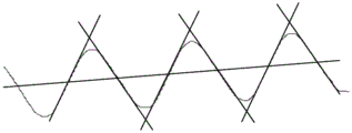
3)如图7所示,在同一连通集合中,依次取螺纹边轮廓中点,过该点,垂直于该螺纹边中径线作直线。若该直线与集合内其他螺纹边有轮廓有交点,则判定两螺纹边配对成功,否则判定不配对。3) As shown in Figure 7, in the same connected set, take the midpoint of the thread edge contour in turn, pass this point, and make a straight line perpendicular to the center diameter of the thread edge. If the line and other thread edges in the set have contours and intersections, it is determined that the two thread edges are paired successfully; otherwise, it is determined that they are not paired.
(17)、将步骤(13)中得到的牙距、牙角和步骤(16)中得到的外径、中径与数据库内螺纹信息进行比对,判断该螺纹是否合格。(17) Comparing the tooth pitch and tooth angle obtained in step (13) and the outer diameter and pitch diameter obtained in step (16) with the internal thread information in the database to determine whether the thread is qualified.
上述步骤(3)中使用了轮廓提取这一图像处理技术。轮廓提取的核心思想就是将图像目标的内部点消除。所谓内部点,需要根据当前像素点的邻域来进行判断,假设邻域窗口为3×3窗口,设当前像素为P(x,y),如果P(x,y)的八个领域像素满足如下条件,则该点即为内部点,如图8所示:The image processing technique of contour extraction is used in the above step (3). The core idea of contour extraction is to eliminate the internal points of the image target. The so-called internal point needs to be judged according to the neighborhood of the current pixel point, assuming that the neighborhood window is a 3×3 window, and the current pixel is set to P(x,y), if the eight domain pixels of P(x,y) satisfy If the following conditions are met, the point is an internal point, as shown in Figure 8:
(1)P(x,y)为目标像素点,假设目标像素为0(黑色),背景像素为255(白色),那么P(x,y)=0;(1) P(x,y) is the target pixel, assuming that the target pixel is 0 (black) and the background pixel is 255 (white), then P(x,y)=0;
(2)P(x,y)的八个邻域像素均为目标像素0;(2) The eight neighboring pixels of P(x,y) are all target pixels 0;
将满足上述两条件的内部点删除,换为背景像素,即可得到图像的轮廓图。Delete the interior points that satisfy the above two conditions and replace them with background pixels, and then the contour map of the image can be obtained.
上述步骤(8)中使用了双三次线性插值的方法来放大图像,以提高测量精度。该方法的基本原理是找到目标图像的每个像素点在源图像中对应的像素点,再根据源图像中距离对应像素点最近的16个像素点的值作为计算目标图像像素点的值的参数,利用BiCubic基函数求出16个像素点的权重,目标图像的像素点的值等于这16个像素点的值的加权叠加。In the above step (8), the method of bicubic linear interpolation is used to enlarge the image to improve the measurement accuracy. The basic principle of this method is to find the corresponding pixel of each pixel of the target image in the source image, and then use the value of the 16 pixels closest to the corresponding pixel in the source image as the parameter to calculate the value of the pixel of the target image , using the BiCubic basis function to obtain the weight of 16 pixels, the value of the pixel of the target image is equal to the weighted superposition of the values of these 16 pixels.
具体的,假设源图像A大小为m×n,缩放K倍的目标图像B大小为M×N,即K=M/m。设目标图像上的B(X,Y)对应在源图像上的A(x,y),根据比例关系有x/X=m/M=1/K,可以得到目标图像上的点B(X,Y)在源图像A上对应的坐标A(x,y)=A(X×m/M,Y×n/N)=A(X/K,Y/K)。如图9所示,P点就是目标图像在B(X,Y)处对应于源图像A中的位置,P坐标的位置会出现小数部分,所以假设P的坐标为P(x+u,y+v),其中x、y分别表示整数部分,u、v分别表示小数部分。由此可以找到最近的16个像素的位置,在这里用aij(i,j=0,1,2,3)表示。Specifically, it is assumed that the size of the source image A is m×n, and the size of the target image B scaled by K times is M×N, that is, K=M/m. Let B(X,Y) on the target image correspond to A(x,y) on the source image, according to the proportional relationship x/X=m/M=1/K, the point B(X) on the target image can be obtained , Y) on the source image A corresponds to the coordinates A(x, y)=A(X×m/M, Y×n/N)=A(X/K, Y/K). As shown in Figure 9, point P is the position of the target image at B(X,Y) corresponding to the source image A, and the position of the P coordinate will have a fractional part, so it is assumed that the coordinate of P is P(x+u,y +v), where x and y represent the integer part, respectively, and u and v represent the fractional part, respectively. From this, the position of the nearest 16 pixels can be found, denoted here by a ij (i,j=0,1,2,3).
BiCubic基函数形式如下:The BiCubic basis function has the following form:

其中,a取-0.5。Among them, a takes -0.5.
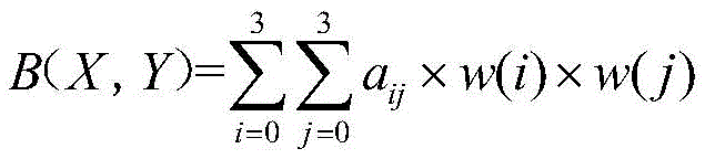
BiCubic基函数是一维的,而像素是二维的,所以要将像素点的行和列分开计算。BiCubic函数中的参数x表示该像素点到P点的距离,例如图9中a00距离P(x+u,y+v)的距离为(1+u,1+v),因此a00的横坐标权重i_0=W(1+u),纵坐标权重j_0=W(1+v),a00对B(X,Y)的贡献值为:(a00的像素值)×i_0×j_0。分别计算剩下的15个点可得B(X,Y)像素值为:BiCubic basis functions are one-dimensional, and pixels are two-dimensional, so the rows and columns of pixels should be calculated separately. The parameter x in the BiCubic function represents the distance from the pixel to point P. For example, the distance between a 00 and P(x+u, y+v) in Figure 9 is (1+u, 1+v), so the distance of a 00 is (1+u, 1+v). The abscissa weight i_0=W(1+u), the ordinate weight j_0=W(1+v), the contribution value of a 00 to B(X, Y) is: (pixel value of a 00 )×i_0×j_0. Calculate the remaining 15 points separately to get the B(X,Y) pixel value:
由此计算出目标图像中的每个像素点的值,从而得到目标图像。From this, the value of each pixel in the target image is calculated to obtain the target image.
上述步骤(9)中使用Canny边缘检测来提取放大了的螺纹边缘。对图像进行边缘检测需要满足两个条件:1、有效地抑制噪声;2、尽量精确地确定边缘位置。Canny边缘检测主要分为4个步骤:Canny edge detection is used in the above step (9) to extract the enlarged thread edge. The edge detection of an image needs to meet two conditions: 1. Effectively suppress noise; 2. Determine the edge position as accurately as possible. Canny edge detection is mainly divided into 4 steps:
(1)去噪(1) Denoising
图像的去噪是通过高斯滤波来实现的。高斯滤波是一种根据待滤波的像素点及其邻域的灰度值按照一定的参数规则进行加权平均的滤波方法。具体可用源图像与高斯模板进行卷积从而得到去噪图像,其中3×3的高斯模板为:Image denoising is achieved by Gaussian filtering. Gaussian filtering is a filtering method that performs weighted average according to certain parameter rules according to the gray value of the pixel to be filtered and its neighborhood. Specifically, the source image can be convolved with a Gaussian template to obtain a denoised image, where the 3×3 Gaussian template is:

(2)用一阶偏导的有限差分来计算梯度的幅值和方向(2) Use the finite difference of the first-order partial derivatives to calculate the magnitude and direction of the gradient
关于图像灰度值的梯度可使用一阶有限差分来近似,这样可以获得图像在x和y方向上偏导数的两个矩阵。Canny边缘检测采用卷积算子为:The gradient with respect to the gray value of the image can be approximated using a first-order finite difference, so that two matrices of partial derivatives of the image in the x and y directions can be obtained. Canny edge detection uses the convolution operator as:

g(i,j)为对应坐标像素点值,由此计算得x向一阶偏导数为:g(i,j) is the pixel value of the corresponding coordinate, and the first-order partial derivative in the x direction is calculated as:

y向一阶偏导数为:The first-order partial derivative of y is:

梯度幅值为:The gradient magnitude is:

梯度方向为:The gradient direction is:
θ=arctan(fy(i,j)/fx(i,j))θ=arctan(f y (i,j)/f x (i,j))
(3)对梯度幅值进行非极大值抑制(3) Non-maximum suppression of gradient amplitude
非极大值抑制首先要将角度划分为四个方向范围:0°(水平)、-45°、90°(垂直)、+45°,接着在3×3区域的四个基本方向进行非极大值抑制,如图10所示,保留沿其方向上邻域梯度幅值的最大值。Non-maximum suppression first divides the angle into four direction ranges: 0° (horizontal), -45°, 90° (vertical), +45°, and then performs non-polarization in the four basic directions of the 3×3 area. Large value suppression, as shown in Figure 10, retains the maximum value of the neighborhood gradient magnitude along its direction.
(4)双阈值检测和连接边缘(4) Double threshold detection and connection edge
Canny算法采用双阈值法来减少假边缘数量。选择两个阈值,根据高阈值得到一个边缘图像,这样一个图像含有很少的假边缘,但由于阈值较高,产生的边缘可能不闭合,此时可在,轮廓断点的8邻域中寻找满足低阈值的点,再根据此点收集新的边缘,直到整个图像边缘闭合。Canny's algorithm uses a double-threshold method to reduce the number of false edges. Select two thresholds, and obtain an edge image according to the high threshold. Such an image contains few false edges, but due to the high threshold, the generated edges may not be closed. At this time, you can find it in the 8 neighborhoods of the contour breakpoint. Points that meet the low threshold, and then collect new edges based on this point, until the entire image edge is closed.
上述步骤(12)中使用了最小二乘法来拟合直线。最小二乘法是一种通过最小化误差的平方和寻找数据的最佳匹配函数,设最佳匹配函数为y=kx+b,参数求解公式如下:In the above step (12), the least squares method is used to fit the straight line. The least squares method is a method of finding the best matching function of data by minimizing the sum of squares of errors. Let the best matching function be y=kx+b, and the parameter solving formula is as follows:


以上所述,仅是本发明的较佳实施例而已,并非对本发明作任何形式上的限制,虽然本发明已以较佳实施例揭露如上,然而并非用以限定本发明,任何熟悉本专业的技术人员,在不脱离本发明技术方案范围内,当可利用上述揭示的技术内容作出些许更动或修饰为等同变化的等效实施例,但凡是未脱离本发明技术方案的内容,依据本发明的技术实质对以上实施例所作的任何简单修改、等同变化与修饰,均仍属于本发明技术方案的范围内。The above are only preferred embodiments of the present invention, and do not limit the present invention in any form. Although the present invention has been disclosed above with preferred embodiments, it is not intended to limit the present invention. Technical personnel, within the scope of the technical solution of the present invention, can make some changes or modifications to equivalent embodiments of equivalent changes by using the technical content disclosed above, but any content that does not depart from the technical solution of the present invention, according to the present invention Any simple modifications, equivalent changes and modifications made to the above embodiments still fall within the scope of the technical solutions of the present invention.
Claims (1)


Priority Applications (1)
| Application Number | Priority Date | Filing Date | Title |
|---|---|---|---|
| CN201810987096.3A CN109060836B (en) | 2018-08-28 | 2018-08-28 | Machine vision-based high-pressure oil pipe joint external thread detection method |
Applications Claiming Priority (1)
| Application Number | Priority Date | Filing Date | Title |
|---|---|---|---|
| CN201810987096.3A CN109060836B (en) | 2018-08-28 | 2018-08-28 | Machine vision-based high-pressure oil pipe joint external thread detection method |
Publications (2)
| Publication Number | Publication Date |
|---|---|
| CN109060836A CN109060836A (en) | 2018-12-21 |
| CN109060836B true CN109060836B (en) | 2020-08-25 |
Family
ID=64756254
Family Applications (1)
| Application Number | Title | Priority Date | Filing Date |
|---|---|---|---|
| CN201810987096.3A Active CN109060836B (en) | 2018-08-28 | 2018-08-28 | Machine vision-based high-pressure oil pipe joint external thread detection method |
Country Status (1)
| Country | Link |
|---|---|
| CN (1) | CN109060836B (en) |
Families Citing this family (16)
| Publication number | Priority date | Publication date | Assignee | Title |
|---|---|---|---|---|
| CN109781024B (en) * | 2018-12-27 | 2021-04-30 | 中国石油天然气集团有限公司 | Petroleum pipe external thread parameter measuring and positioning method based on contour |
| CN109827515A (en) * | 2018-12-28 | 2019-05-31 | 甘肃第一建设集团有限责任公司 | A system and method for detecting the size of a threaded steel wire head |
| CN109632814A (en) * | 2019-02-01 | 2019-04-16 | 东莞中科蓝海智能视觉科技有限公司 | Part defect detection method |
| CN110260825B (en) * | 2019-07-10 | 2020-12-25 | 陕西理工大学 | Image method thread form angle solving method |
| CN110706243B (en) * | 2019-09-30 | 2022-10-21 | Oppo广东移动通信有限公司 | Feature point detection method, device, storage medium and electronic device |
| CN111402210B (en) * | 2020-03-03 | 2022-11-11 | 山东师范大学 | A method and system for super-resolution localization of single-molecule fluorescence signal images |
| CN111583114B (en) * | 2020-04-30 | 2023-02-24 | 安徽工业大学 | Automatic measuring device and measuring method for pipeline thread |
| CN111882542A (en) * | 2020-07-29 | 2020-11-03 | 南通大学 | An automatic and precise measurement method of high-precision thread based on AA R2Unet and HMM |
| CN112508892B (en) * | 2020-11-27 | 2024-10-18 | 中国铁路南宁局集团有限公司 | Method and system for detecting tiny foreign matters on railway track surface based on machine vision |
| CN113902667B (en) * | 2021-08-23 | 2022-06-14 | 浙大宁波理工学院 | Thread turning identification method and system for machine vision |
| CN113701632B (en) * | 2021-09-01 | 2024-02-13 | 威海北洋电气集团股份有限公司 | A thread detection method based on difference |
| CN115808429A (en) * | 2021-09-13 | 2023-03-17 | 青岛中瑞泰软控科技股份有限公司 | A system and method for detecting oil pipe thread defects |
| CN114235688A (en) * | 2021-11-23 | 2022-03-25 | 德创智控科技(苏州)有限公司 | A system and method for visual inspection of threads and threads for mobile phone frame |
| CN116824577B (en) * | 2023-08-31 | 2023-11-24 | 泰安金冠宏食品科技有限公司 | Prefabricated vegetable production detection method based on machine vision |
| CN118565346B (en) * | 2024-07-30 | 2024-10-29 | 中国石油大学(华东) | A multi-parameter integrated visual measurement method for external threads of oil pipes |
| CN119554980B (en) * | 2024-10-18 | 2025-11-21 | 南京理工大学 | Multi-vision automobile flange plate thread detection device and method based on mechanical arm |
Family Cites Families (5)
| Publication number | Priority date | Publication date | Assignee | Title |
|---|---|---|---|---|
| CN103245296A (en) * | 2013-04-25 | 2013-08-14 | 北方民族大学 | Screw thread parameter measurement method based on image measurement and processing |
| CN105241380A (en) * | 2015-09-30 | 2016-01-13 | 广州超音速自动化科技股份有限公司 | Visual detection method for zigzag screw thread |
| CN105157611A (en) * | 2015-09-30 | 2015-12-16 | 广州超音速自动化科技股份有限公司 | Visual detection method of pipe thread |
| CN107687812A (en) * | 2017-09-19 | 2018-02-13 | 南通爱慕希机械股份有限公司 | A kind of external screw thread intelligent checking system based on machine vision |
| CN108387516A (en) * | 2018-01-25 | 2018-08-10 | 陕西方元预应力机械有限公司 | Threading defects detection device and detection method based on CCD camera image processing technologies |
-
2018
- 2018-08-28 CN CN201810987096.3A patent/CN109060836B/en active Active
Also Published As
| Publication number | Publication date |
|---|---|
| CN109060836A (en) | 2018-12-21 |
Similar Documents
| Publication | Publication Date | Title |
|---|---|---|
| CN109060836B (en) | Machine vision-based high-pressure oil pipe joint external thread detection method | |
| CN109003258B (en) | A high-precision sub-pixel circular part measurement method | |
| CN108921176B (en) | Pointer instrument positioning and identifying method based on machine vision | |
| CN112686920A (en) | Visual measurement method and system for geometric dimension parameters of circular part | |
| CN107941808A (en) | 3D printing Forming Quality detecting system and method based on machine vision | |
| CN107742289A (en) | A detection method of rotating body workpiece based on machine vision | |
| CN108470349A (en) | A kind of milli machine part dimension measurement screening technique under movement background | |
| CN113689415A (en) | Steel pipe wall thickness online detection method based on machine vision | |
| CN104112269A (en) | Solar cell laser-marking parameter detection method based on machine vision and system thereof | |
| CN111475016A (en) | Assembly process geometric parameter self-adaptive measurement system and method based on computer vision | |
| CN111815575B (en) | Bearing steel ball part detection method based on machine vision | |
| CN105184792B (en) | A kind of saw blade wear extent On-line Measuring Method | |
| CN107633502B (en) | A Bullseye Recognition Method for Automatic Centering of Shaft Hole Assembly | |
| CN114581385B (en) | Weld defect area mapping method based on circle positioning | |
| CN104657988A (en) | Image segmentation method for micro-fine cohesive core particles based on angular point and curvature detection | |
| CN109341570B (en) | A method and system for detecting internal threads based on machine vision | |
| CN119086589A (en) | Bridge welding quality detection method based on gray-relative depth fitting vision technology | |
| CN118644456A (en) | Workpiece surface defect detection and early warning method based on 3D vision | |
| CN106989672A (en) | A kind of workpiece measuring based on machine vision | |
| CN111353981A (en) | Gear detection method, system and storage medium based on machine vision | |
| CN105631857B (en) | A kind of scratch detection method and apparatus of optical element surface | |
| CN103337067B (en) | The visible detection method of single needle scan-type screw measurement instrument probe X-axis rotating deviation | |
| Zhao et al. | Design of real-time steel bars recognition system based on machine vision | |
| CN108335332A (en) | A kind of axial workpiece central axes measurement method based on binocular vision | |
| CN117252807A (en) | A method for detecting parameters and characteristics of detonation tubes based on machine vision |
Legal Events
| Date | Code | Title | Description |
|---|---|---|---|
| PB01 | Publication | ||
| PB01 | Publication | ||
| SE01 | Entry into force of request for substantive examination | ||
| SE01 | Entry into force of request for substantive examination | ||
| GR01 | Patent grant | ||
| GR01 | Patent grant | ||
| EE01 | Entry into force of recordation of patent licensing contract |
Application publication date: 20181221 Assignee: Hangzhou lanque technology partnership (L.P.) Assignor: NANTONG University Contract record no.: X2021980012590 Denomination of invention: External thread detection method of high pressure oil pipe joint based on machine vision Granted publication date: 20200825 License type: Common License Record date: 20211119 |
|
| EE01 | Entry into force of recordation of patent licensing contract |