CN108942908B - A rotary joint variable stiffness actuator - Google Patents
A rotary joint variable stiffness actuator Download PDFInfo
- Publication number
- CN108942908B CN108942908B CN201810874481.7A CN201810874481A CN108942908B CN 108942908 B CN108942908 B CN 108942908B CN 201810874481 A CN201810874481 A CN 201810874481A CN 108942908 B CN108942908 B CN 108942908B
- Authority
- CN
- China
- Prior art keywords
- base
- disc
- output
- adjusting
- stiffness
- Prior art date
- Legal status (The legal status is an assumption and is not a legal conclusion. Google has not performed a legal analysis and makes no representation as to the accuracy of the status listed.)
- Active
Links
- 230000005540 biological transmission Effects 0.000 claims abstract description 55
- 230000007246 mechanism Effects 0.000 claims abstract description 44
- 239000003638 chemical reducing agent Substances 0.000 claims description 70
- 230000000149 penetrating effect Effects 0.000 claims description 9
- 206010023230 Joint stiffness Diseases 0.000 claims 5
- 230000008859 change Effects 0.000 abstract description 8
- 238000005265 energy consumption Methods 0.000 abstract description 6
- 230000033001 locomotion Effects 0.000 description 11
- 238000010586 diagram Methods 0.000 description 6
- 238000000034 method Methods 0.000 description 4
- 230000001360 synchronised effect Effects 0.000 description 3
- 230000009286 beneficial effect Effects 0.000 description 1
- 230000007547 defect Effects 0.000 description 1
- 238000005516 engineering process Methods 0.000 description 1
- 238000009434 installation Methods 0.000 description 1
- 230000003993 interaction Effects 0.000 description 1
- 239000000463 material Substances 0.000 description 1
- 230000036316 preload Effects 0.000 description 1
- 230000008569 process Effects 0.000 description 1
- 230000009467 reduction Effects 0.000 description 1
- 230000004044 response Effects 0.000 description 1
Images


Classifications
-
- B—PERFORMING OPERATIONS; TRANSPORTING
- B25—HAND TOOLS; PORTABLE POWER-DRIVEN TOOLS; MANIPULATORS
- B25J—MANIPULATORS; CHAMBERS PROVIDED WITH MANIPULATION DEVICES
- B25J17/00—Joints
-
- B—PERFORMING OPERATIONS; TRANSPORTING
- B25—HAND TOOLS; PORTABLE POWER-DRIVEN TOOLS; MANIPULATORS
- B25J—MANIPULATORS; CHAMBERS PROVIDED WITH MANIPULATION DEVICES
- B25J9/00—Programme-controlled manipulators
- B25J9/10—Programme-controlled manipulators characterised by positioning means for manipulator elements
Landscapes
- Engineering & Computer Science (AREA)
- Robotics (AREA)
- Mechanical Engineering (AREA)
- Manipulator (AREA)
- Retarders (AREA)
Abstract
本发明公开了一种转动关节变刚度致动器,包括支撑机座,支撑机座包括底座、外壳和两个底座连接螺钉,底座位于外壳的下端,且外壳的下端和底座的上端相抵触,两个底座连接螺钉的一端均贯穿底座并延伸至外壳内,所述外壳上设有力矩输出机构,所述力矩输出机构上设有两个相互平行的输出盘连接销,两个输出盘连接销均位于外壳内,两个输出盘连接销上设有刚度调整机构,所述底座的下端一侧设有主传动机构。本发明能改变弹簧片的有效作用长度,实现输出刚度的变化,主传动机构和调刚盘同步旋转实现定刚度输出,异步旋转实现变刚度输出,便于输出刚度解耦,从而方便控制算法,降低了摩擦,有利于降低能耗,且输出盘能够实现连续回转,结构紧凑,体积小。
The invention discloses a rotary joint variable stiffness actuator, comprising a support base, the support base includes a base, a shell and two base connecting screws, the base is located at the lower end of the shell, and the lower end of the shell and the upper end of the base are in conflict, One end of the two base connecting screws penetrates through the base and extends into the casing, the casing is provided with a torque output mechanism, and the torque output mechanism is provided with two parallel output disk connecting pins, two output disk connecting pins Both are located in the casing, the two output disc connecting pins are provided with rigidity adjustment mechanisms, and the lower end side of the base is provided with a main transmission mechanism. The invention can change the effective length of the spring piece, realize the change of the output stiffness, the main transmission mechanism and the rigidity adjusting plate rotate synchronously to realize the constant stiffness output, and the asynchronous rotation realizes the variable stiffness output, which is convenient for the decoupling of the output stiffness, so as to facilitate the control algorithm and reduce the The friction is reduced, which is conducive to reducing energy consumption, and the output disc can realize continuous rotation, with compact structure and small volume.
Description
技术领域technical field
本发明涉及机器人技术领域,尤其涉及一种转动关节变刚度致动器。The invention relates to the technical field of robots, in particular to a variable stiffness actuator of a rotary joint.
背景技术Background technique
随着机器人技术的发展,机器人的适用范围越来越广,新一代协作型工业机器人、服务机器人、助力及医疗康复机器人等,大多数均与人类共享工作空间且存在频繁的物理接触和力交换。2015年德国大众发生机器人攻击人的事件,说明机器人尚不能安全、在线地与人并肩工作,因此,人机交互的安全性变得尤为重要。传统的机器人是刚性的,虽然利用大量传感器和复杂的控制算法能够实现一定的柔性,但是传感器的分辨率以及控制系统的响应速度使柔顺控制大打折扣。然而刚度可调的致动器成为国内外研究的热点问题,变刚度致动器能够有效改善机器人的动态特性,当机器人与外界发生碰撞时,降低输出刚度,减小碰撞冲击,较高的输出刚度,又能保证位置精度,刚度调整过程中,柔性元件能够进行能量存储与释放,不仅能够降低系统能耗,同时又能为弹跳机器人等提供启动爆发性。With the development of robotics technology, the scope of application of robots is getting wider and wider. Most of the new generation of collaborative industrial robots, service robots, assistance and medical rehabilitation robots share workspace with humans and there is frequent physical contact and force exchange. . In 2015, the incident of robots attacking people in German Volkswagen showed that robots cannot work side by side with people safely and online. Therefore, the safety of human-computer interaction has become particularly important. Traditional robots are rigid. Although a large number of sensors and complex control algorithms can be used to achieve a certain degree of flexibility, the resolution of the sensors and the response speed of the control system greatly reduce the compliance control. However, actuators with adjustable stiffness have become a hot research topic at home and abroad. Variable stiffness actuators can effectively improve the dynamic characteristics of the robot. When the robot collides with the outside world, it reduces the output stiffness, reduces the impact of the collision, and has a higher output. In the process of stiffness adjustment, the flexible element can store and release energy, which can not only reduce the energy consumption of the system, but also provide start-up explosiveness for bouncing robots.
目前,已有的变刚度致动器,根据变刚度原理的不同,都存在不同程度的缺陷,如输出力较小,体积重量大,运动范围小,刚度较小,刚度调整能耗大,控制算法复杂等不足。具体来说,采用弹簧预紧的调节方式不够节能;采用特殊材料实现变刚度其性能难以保证,且控制复杂;采用杠杆原理调节方式摩擦能耗大,结构复杂笨重,为此,我们提出了一种转动关节变刚度致动器来解决上述问题。At present, the existing variable stiffness actuators have different degrees of defects according to the principle of variable stiffness, such as small output force, large volume and weight, small range of motion, small stiffness, large energy consumption for stiffness adjustment, control The algorithm is complicated and so on. Specifically, the spring preload adjustment method is not energy-efficient; the use of special materials to achieve variable stiffness is difficult to ensure performance, and the control is complicated; the lever principle adjustment method has large frictional energy consumption, and the structure is complex and bulky. A rotary joint variable stiffness actuator is proposed to solve the above problems.
发明内容SUMMARY OF THE INVENTION
本发明的目的是为了解决现有技术中存在的缺点,而提出的一种转动关节变刚度致动器。The purpose of the present invention is to propose a rotary joint variable stiffness actuator in order to solve the shortcomings existing in the prior art.
为了实现上述目的,本发明采用了如下技术方案:In order to achieve the above object, the present invention adopts the following technical solutions:
一种转动关节变刚度致动器,包括支撑机座,所述支撑机座包括底座、外壳和两个底座连接螺钉,所述底座位于外壳的下端,且外壳的下端和底座的上端相抵触,两个底座连接螺钉的一端均贯穿底座并延伸至外壳内,所述外壳上设有力矩输出机构,所述力矩输出机构上设有两个相互平行的输出盘连接销,两个输出盘连接销均位于外壳内,两个输出盘连接销上设有刚度调整机构,所述底座的下端一侧设有主传动机构,所述底座的下端另一侧设有刚度传动机构。A rotary joint variable stiffness actuator includes a support base, the support base includes a base, a casing and two base connecting screws, the base is located at the lower end of the casing, and the lower end of the casing and the upper end of the base are in conflict, One end of the two base connecting screws penetrates through the base and extends into the casing, the casing is provided with a torque output mechanism, and the torque output mechanism is provided with two parallel output disk connecting pins, two output disk connecting pins Both are located in the casing, the two output disc connecting pins are provided with a rigidity adjustment mechanism, one side of the lower end of the base is provided with a main transmission mechanism, and the other side of the lower end of the base is provided with a rigidity transmission mechanism.
优选地,所述力矩输出机构包括设置在外壳内顶部的输出盘轴承,所述输出盘轴承内贯穿设有输出盘,且输出盘的上端贯穿外壳内的顶部并延伸至外壳的上端,两个输出盘连接销分别固定在输出盘的下端两侧。Preferably, the torque output mechanism includes an output disc bearing arranged at the top of the housing, an output disc is provided through the output disc bearing, and the upper end of the output disc penetrates through the top of the housing and extends to the upper end of the housing, and the two The output disc connecting pins are respectively fixed on both sides of the lower end of the output disc.
优选地,所述刚度调整机构包括分别贯穿设置在两个输出盘连接销下端的弹簧片,所述弹簧片的两侧均设有滚子,且弹簧片的两侧分别抵触在两个滚子的相对一侧,所述滚子的两端均转动套接有滚子滑块微型轴承,且同一侧的两个滚子滑块微型轴承为一组,其中一组的两个滚子滑块微型轴承上共同安装有第一滚子滑块侧板,另一组的两个滚子滑块微型轴承上共同安装有第二滚子滑块侧板,所述第一滚子滑块侧板和第二滚子滑块侧板的两端分别贯穿设有滚子滑块螺钉,同一侧的两个滚子滑块螺钉为一组,同一组的两个滚子滑块螺钉之间共同螺合有滚子滑块连接板,两个滚子滑块连接板均位于两个第一滚子滑块侧板之间,两个滚子均位于两个滚子滑块连接板之间,两个弹簧片之间设有十字架滑轨,所述十字架滑轨的两侧均螺合有弹簧片固定螺钉,且两个弹簧片分别螺纹套接在两个弹簧片固定螺钉上,所述十字架滑轨的四角分别抵触在四个滚子滑块连接板的一侧,所述十字架滑轨上贯穿设有滑动轴承,且滑动轴承的两端分别延伸至十字架滑轨的两侧,所述滑动轴承的两端均套接有随动滑块,所述滑动轴承的两端均设有滑轨连接件,所述滑轨连接件上均螺纹套接有滑轨连接螺钉,所述滑轨连接螺钉的一端贯穿滑轨连接件和滑动轴承并延伸至滑动轴承内。Preferably, the stiffness adjustment mechanism includes spring sheets respectively disposed through the lower ends of the connecting pins of the two output discs, rollers are provided on both sides of the spring sheets, and the two sides of the spring sheets are respectively in contact with the two rollers On the opposite side of the roller, both ends of the roller are rotatably sleeved with roller-slider miniature bearings, and two roller-slider miniature bearings on the same side are a group, and two roller-slider bearings in one group are A first roller slider side plate is commonly installed on the miniature bearing, and a second roller slider side plate is commonly installed on the two roller slider micro bearings of the other group. The first roller slider side plate is Roller block screws are respectively provided through the two ends of the side plate of the second roller block block and the two roller block block screws on the same side. A roller block connecting plate is combined, the two roller block connecting plates are located between the two first roller block side plates, the two rollers are both located between the two roller block connecting plates, and the two A cross slide rail is arranged between the spring pieces, and spring piece fixing screws are screwed on both sides of the cross slide rail, and the two spring pieces are respectively threaded on the two spring piece fixing screws. The four corners of the rail are respectively in contact with one side of the connecting plates of the four roller sliders, the sliding bearings are provided through the cross sliding rails, and the two ends of the sliding bearings extend to both sides of the cross sliding rails respectively. Both ends of the sliding bearing are sleeved with follower sliders, and both ends of the sliding bearing are provided with slide rail connectors, and slide rail connection screws are threadedly sleeved on the slide rail connectors, and the slide rail connection screws are One end penetrates the sliding rail connecting piece and the sliding bearing and extends into the sliding bearing.
优选地,所述主传动机构包括设置在底座下端一侧的主传动行星减速器,所述主传动行星减速器的上端四角均贯穿设有主传动行星减速器固定螺钉,四个主传动行星减速器固定螺钉的上端均贯穿底座并延伸至底座内,所述主传动行星减速器的下端设有主传动电机,且主传动行星减速器安装在主传动电机的输出轴上,所述主传动行星减速器的输出轴贯穿底座并延伸至底座内的底部,所述主传动行星减速器的输出轴末端固定有主驱动齿轮,所述底座内的侧壁上转动连接有齿圈,且主驱动齿轮和齿圈相啮合,所述齿圈的下端等间距贯穿设有四个齿圈连接螺钉,且齿圈连接螺钉的上端均贯穿齿圈并延伸至齿圈的上端,四个齿圈连接螺钉的上端共同螺合有下连接盘,所述下连接盘的上端设有上连接盘,且上连接盘的下端与下连接盘的上端相抵触,所述上连接盘内的底部和下连接盘之间共同螺合有第二上连接盘连接螺钉,所述上连接盘的上端两侧均螺合有第一上连接盘连接螺钉,两个滑轨连接件分别螺纹套接在两个第一上连接盘连接螺钉上,所述上连接盘和下连接盘上共同转动套接有主传动轴承,且主传动轴承安装在外壳内。Preferably, the main transmission mechanism includes a main transmission planetary reducer arranged on one side of the lower end of the base, the upper end of the main transmission planetary reducer is provided with fixing screws of the main transmission planetary reducer, and the four main transmission planetary reduction The upper ends of the fixing screws of the gear reducer penetrate through the base and extend into the base. The lower end of the main drive planetary reducer is provided with a main drive motor, and the main drive planetary reducer is installed on the output shaft of the main drive motor. The output shaft of the reducer penetrates the base and extends to the bottom of the base, the end of the output shaft of the main drive planetary reducer is fixed with a main drive gear, the side wall in the base is rotatably connected with a ring gear, and the main drive gear It meshes with the ring gear, the lower end of the ring gear is provided with four ring gear connecting screws at equal intervals, and the upper ends of the ring gear connecting screws all penetrate the ring gear and extend to the upper end of the ring gear. The upper end is screwed together with a lower connection plate, the upper end of the lower connection plate is provided with an upper connection plate, and the lower end of the upper connection plate is in conflict with the upper end of the lower connection plate, and the bottom in the upper connection plate and the lower connection plate are connected. A second upper connecting plate connecting screw is screwed together between the two upper connecting plates, the first upper connecting plate connecting screw is screwed on both sides of the upper end of the upper connecting plate, and the two sliding rail connecting pieces are respectively threadedly sleeved on the two first upper connecting plates. On the connecting plate connecting screws, the upper connecting plate and the lower connecting plate are jointly rotatably sleeved with a main transmission bearing, and the main transmission bearing is installed in the casing.
优选地,所述刚度传动机构包括设置在底座下端另一侧的调刚行星减速器,且调刚行星减速器位于主传动行星减速器的一侧,所述调刚行星减速器的上端四角均贯穿设有调刚行星减速器固定螺钉,四个调刚行星减速器固定螺钉的上端均贯穿底座并延伸至底座内,所述调刚行星减速器的下端设有调刚电机,且调刚行星减速器安装在调刚电机的输出轴上,所述调刚行星减速器的输出轴贯穿底座并延伸至底座内的底部,所述调刚行星减速器的输出轴末端固定有调刚驱动齿轮,所述底座内的底部安装有中心轴轴承,且中心轴轴承位于调刚驱动齿轮和主驱动齿轮之间,所述中心轴轴承内贯穿设有中心轴,所述中心轴的下端套设有套筒,所述中心轴上固定有中心轴齿轮,且套筒位于中心轴齿轮的下端,所述中心轴齿轮上安装有齿轮键,所述中心轴齿轮和调刚驱动齿轮相啮合,所述中心轴的上端位于上连接盘和下连接盘内,所述中心轴上固定有调刚轴承,所述调刚轴承位于中心轴齿轮的上端,所述调刚轴承安装在上连接盘和下连接盘内,所述中心轴上安装有调刚盘,且调刚盘位于上连接盘内,所述调刚盘上安装有调刚盘键,所述调刚盘上设有轴端挡圈,所述轴端挡圈上贯穿设有挡圈螺钉,所述挡圈螺钉的下端依次贯穿轴端挡圈、调刚盘和中心轴并延伸至中心轴内,所述调刚盘的上端安装有两个相互平行的调刚连杆,同一侧的第一滚子滑块侧板和随动滑块为一组,两组第一滚子滑块侧板和随动滑块分别和两个调刚连杆相对应,同一组内的第一滚子滑块侧板和随动滑块分别安装在其中一个调刚连杆的上端两侧。Preferably, the rigidity transmission mechanism includes a rigidity-adjusting planetary reducer disposed on the other side of the lower end of the base, and the rigidity-adjusting planetary reducer is located on one side of the main drive planetary reducer, and the four corners of the upper end of the rigidity-adjusting planetary reducer are There are fixed screws of the planetary reducer for adjusting the rigidity throughout, and the upper ends of the four fixing screws for the planetary reducer for adjusting the rigidity all penetrate the base and extend into the base. The reducer is installed on the output shaft of the just-adjusting motor, the output shaft of the just-adjusting planetary reducer penetrates through the base and extends to the bottom of the base, and the end of the output shaft of the just-adjusting planetary reducer is fixed with an adjusting-rigid drive gear, A central shaft bearing is installed at the bottom of the base, and the central shaft bearing is located between the rigidity adjustment drive gear and the main drive gear. A central shaft is arranged through the central shaft bearing, and a sleeve is sleeved at the lower end of the central shaft. A central shaft gear is fixed on the central shaft, and the sleeve is located at the lower end of the central shaft gear. A gear key is installed on the central shaft gear. The upper end of the shaft is located in the upper connecting plate and the lower connecting plate, the rigidity adjusting bearing is fixed on the central shaft, the rigidity adjusting bearing is located at the upper end of the central shaft gear, and the rigidity adjusting bearing is installed on the upper connecting plate and the lower connecting plate. Inside, an adjustment disc is installed on the central shaft, and the adjustment disc is located in the upper connecting disc. A rigid adjustment disc key is installed on the rigid adjustment disc. The shaft end retaining ring is provided with retaining ring screws, and the lower end of the retaining ring screw penetrates the shaft end retaining ring, the adjustment disc and the central shaft in sequence and extends into the central shaft, and the upper end of the rigid adjustment disc is installed with two The first roller block side plate and the follower block on the same side are a group, and the two sets of the first roller block side plate and the follower block are connected to the two sets of rigidity adjustment rods, respectively. Corresponding to the connecting rods, the side plates of the first roller block and the follower block in the same group are respectively installed on both sides of the upper end of one of the rigidity adjusting connecting rods.
优选地,所述主传动行星减速器的输出轴为D形,主传动电机上设有编码器。Preferably, the output shaft of the main drive planetary reducer is D-shaped, and an encoder is provided on the main drive motor.
优选地,所述调刚行星减速器的输出轴为D形,所述调刚电机上设有编码器。Preferably, the output shaft of the planetary reducer for adjusting the rigidity is D-shaped, and the motor for adjusting the rigidity is provided with an encoder.
优选地,所述外壳上设有绝对位置编码器。Preferably, an absolute position encoder is provided on the housing.
与现有技术相比,本发明的有益效果是:Compared with the prior art, the beneficial effects of the present invention are:
一、采用类椭圆机构的刚度调整机构,改变随动滑块的相对位置,从而改变弹簧片的有效作用长度,实现输出刚度的变化,主传动机构和调刚盘同步旋转,可实现定刚度输出,异步旋转实现变刚度输出;1. The stiffness adjustment mechanism of the elliptical mechanism is adopted to change the relative position of the follower slider, thereby changing the effective length of the spring sheet and realizing the change of the output stiffness. , asynchronous rotation to achieve variable stiffness output;
二、在结构上,主传动机构、刚度调整机构、刚度传动机构沿外壳轴向布置,结构紧凑,体积小;2. In terms of structure, the main transmission mechanism, the stiffness adjustment mechanism and the stiffness transmission mechanism are arranged along the axial direction of the casing, with compact structure and small volume;
三、在小变形条件下,关节输出刚度近似仅与弹簧片有效作用长度有关,便于输出刚度解耦,从而为控制算法提供了方便;3. Under the condition of small deformation, the output stiffness of the joint is approximately only related to the effective length of the spring sheet, which is convenient for the decoupling of the output stiffness, thus providing convenience for the control algorithm;
四、随动滑块通过滑动轴承与十字架滑轨连接,以及滚子滑块与弹簧片相接触,大大降低了摩擦,有利于降低能耗,且输出盘能够实现连续回转;4. The follower slider is connected with the cross slide rail through the sliding bearing, and the roller slider is in contact with the spring sheet, which greatly reduces the friction, which is conducive to reducing energy consumption, and the output disc can realize continuous rotation;
综上所述,本装置能改变弹簧片的有效作用长度,实现输出刚度的变化,主传动机构和调刚盘同步旋转实现定刚度输出,异步旋转实现变刚度输出,便于输出刚度解耦,从而方便控制算法,降低了摩擦,有利于降低能耗,且输出盘能够实现连续回转,结构紧凑,体积小。To sum up, the device can change the effective length of the spring sheet and realize the change of the output stiffness. The main transmission mechanism and the adjusting plate rotate synchronously to realize the output of constant stiffness, and the asynchronous rotation realizes the output of variable stiffness, which is convenient for the decoupling of the output stiffness. The convenient control algorithm reduces friction and is conducive to reducing energy consumption, and the output disc can realize continuous rotation, with compact structure and small volume.
附图说明Description of drawings
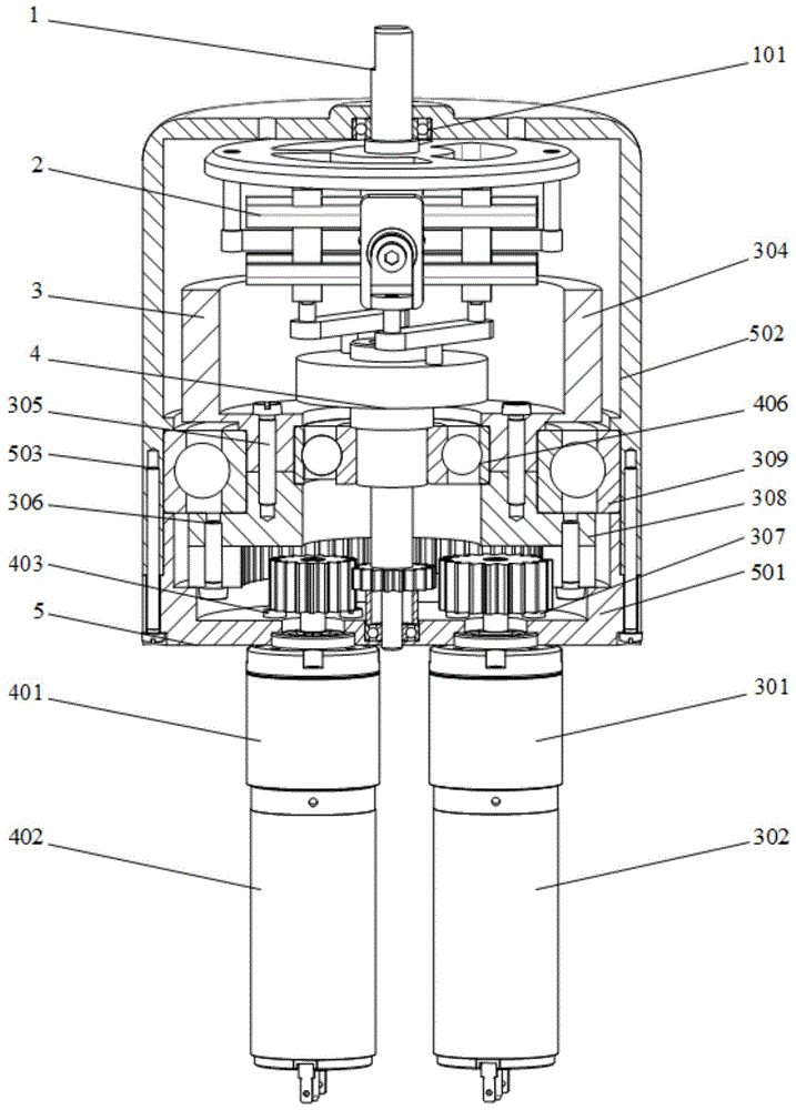
图1为本发明提出的一种转动关节变刚度致动器的结构示意图;1 is a schematic structural diagram of a rotary joint variable stiffness actuator proposed by the present invention;
图2为本发明提出的一种转动关节变刚度致动器的滚子滑块结构示意图;2 is a schematic structural diagram of a roller slider of a rotary joint variable stiffness actuator proposed by the present invention;
图3为本发明提出的一种转动关节变刚度致动器的十字架滑轨及滑块安装示意图;3 is a schematic diagram of the installation of a cross slide rail and a slider of a rotary joint variable stiffness actuator proposed by the present invention;
图4为本发明提出的一种转动关节变刚度致动器的刚度调整机构结构示意图;4 is a schematic structural diagram of a stiffness adjustment mechanism of a rotary joint variable stiffness actuator proposed by the present invention;
图5为本发明提出的一种转动关节变刚度致动器的调刚传动机构结构示意图;5 is a schematic structural diagram of a rigidity-adjusting transmission mechanism of a rotary joint variable-stiffness actuator proposed by the present invention;
图6为本发明提出的一种转动关节变刚度致动器的主传动机构结构示意图。FIG. 6 is a schematic structural diagram of the main transmission mechanism of a rotary joint variable stiffness actuator proposed by the present invention.
图中:1力矩输出机构、101输出盘轴承、102输出盘连接销、103输出盘、2刚度调整机构、201十字架滑轨、202滚子滑块螺钉、203第一滚子滑块侧板、204滚子滑块微型轴承、205弹簧片、206滚子、207滚子滑块连接板、208滑动轴承、209随动滑块、210滑轨连接件、211滑轨连接螺钉、212弹簧片固定螺钉、213第二滚子滑块侧板、3主传动机构、301主传动行星减速器、302主传动电机、303第一上连接盘连接螺钉、304上连接盘、305第二上连接盘连接螺钉、306齿圈连接螺钉、307主传动行星减速器固定螺钉、308下连接盘、309主传动轴承、310主驱动齿轮、311齿圈、4刚度传动机构、401调刚行星减速器、402调刚电机、403调刚行星减速器固定螺钉、404调刚盘、405调刚连杆、406调刚轴承、407调刚驱动齿轮、408齿轮键、409调刚盘键、410轴端挡圈、411挡圈螺钉、412中心轴、413中心轴齿轮、414套筒、415中心轴轴承、5支撑机座、501底座、502外壳、503底座连接螺钉。In the figure: 1 torque output mechanism, 101 output disk bearing, 102 output disk connecting pin, 103 output disk, 2 stiffness adjustment mechanism, 201 cross slide rail, 202 roller slider screw, 203 first roller slider side plate, 204 roller slider miniature bearing, 205 spring plate, 206 roller, 207 roller slider connecting plate, 208 sliding bearing, 209 follower slider, 210 sliding rail connecting piece, 211 sliding rail connecting screw, 212 spring plate fixing Screw, 213 second roller slider side plate, 3 main transmission mechanism, 301 main transmission planetary reducer, 302 main transmission motor, 303 first upper connection plate connecting screw, 304 upper connection plate, 305 second upper connection plate connection Screw, 306 ring gear connecting screw, 307 main drive planetary reducer fixing screw, 308 lower connecting plate, 309 main drive bearing, 310 main drive gear, 311 ring gear, 4 rigidity transmission mechanism, 401 rigidity planetary reducer, 402 adjustment Gang motor, 403 rigid adjustment planetary reducer fixing screw, 404 rigid adjustment disc, 405 rigid adjustment connecting rod, 406 rigid adjustment bearing, 407 rigid adjustment drive gear, 408 gear key, 409 rigid adjustment plate key, 410 shaft end retaining ring, 411 retaining ring screw, 412 center shaft, 413 center shaft gear, 414 sleeve, 415 center shaft bearing, 5 support base, 501 base, 502 shell, 503 base connecting screw.
具体实施方式Detailed ways
下面将结合本发明实施例中的附图,对本发明实施例中的技术方案进行清楚、完整地描述,显然,所描述的实施例仅仅是本发明一部分实施例,而不是全部的实施例。The technical solutions in the embodiments of the present invention will be clearly and completely described below with reference to the accompanying drawings in the embodiments of the present invention. Obviously, the described embodiments are only a part of the embodiments of the present invention, but not all of the embodiments.
参照图1-6,一种转动关节变刚度致动器,包括支撑机座5,支撑机座5包括底座501、外壳502和两个底座连接螺钉503,底座501位于外壳502的下端,且外壳502的下端和底座501的上端相抵触,两个底座连接螺钉503的一端均贯穿底座501并延伸至外壳502内,进行稳定连接,且方便进行拆卸,外壳502上设有力矩输出机构1,力矩输出机构1上设有两个相互平行的输出盘连接销102,两个输出盘连接销102均位于外壳502内,两个输出盘连接销102上设有刚度调整机构2,底座501的下端一侧设有主传动机构3,底座501的下端另一侧设有刚度传动机构4。1-6, a rotary joint variable stiffness actuator includes a
本发明中,力矩输出机构1包括设置在外壳502内顶部的输出盘轴承101,输出盘轴承101内贯穿设有输出盘103,且输出盘103的上端贯穿外壳502内的顶部并延伸至外壳502的上端,方便输出盘103转动,两个输出盘连接销102分别固定在输出盘103的下端两侧,两个输出盘连接销102使输出盘103转动。In the present invention, the
本发明中,刚度调整机构2包括分别贯穿设置在两个输出盘连接销102下端的弹簧片205,弹簧片205的两侧均设有滚子206,且弹簧片205的两侧分别抵触在两个滚子206的相对一侧,方便弹簧片205移动偏转,滚子206的两端均转动套接有滚子滑块微型轴承204,且同一侧的两个滚子滑块微型轴承204为一组,其中一组的两个滚子滑块微型轴承204上共同安装有第一滚子滑块侧板203,另一组的两个滚子滑块微型轴承204上共同安装有第二滚子滑块侧板213,第一滚子滑块侧板203和第二滚子滑块侧板213的两端分别贯穿设有滚子滑块螺钉202,同一侧的两个滚子滑块螺钉202为一组,同一组的两个滚子滑块螺钉202之间共同螺合有滚子滑块连接板207,进行稳定连接,两个滚子滑块连接板207均位于两个第一滚子滑块侧板203之间,两个滚子206均位于两个滚子滑块连接板207之间,滚子206一端通过一个滚子滑块微型轴承204与第一滚子滑块侧板203相连,另一端通过另一个滚子滑块微型轴承204与第二滚子滑块侧板213相连,方便滚子206转动,两个弹簧片205之间设有十字架滑轨201,十字架滑轨201的两侧均螺合有弹簧片固定螺钉212,且两个弹簧片205分别螺纹套接在两个弹簧片固定螺钉212上,弹簧片205一端与十字架滑轨201相连并通过弹簧片固定螺钉212固定,另一端通过输出盘连接销102与输出盘103相连,十字架滑轨201的四角分别抵触在四个滚子滑块连接板207的一侧,十字架滑轨201上贯穿设有滑动轴承208,且滑动轴承208的两端分别延伸至十字架滑轨201的两侧,滑动轴承208的两端均套接有随动滑块209,滑动轴承208的两端均设有滑轨连接件210,滑轨连接件210上均螺纹套接有滑轨连接螺钉211,滑轨连接螺钉211的一端贯穿滑轨连接件210和滑动轴承208并延伸至滑动轴承208内,进行稳定固定,方便进行传动,从而使输出盘103运动。In the present invention, the
本发明中,主传动机构3包括设置在底座501下端一侧的主传动行星减速器301,主传动行星减速器301的上端四角均贯穿设有主传动行星减速器固定螺钉307,四个主传动行星减速器固定螺钉307的上端均贯穿底座501并延伸至底座501内,通过主传动行星减速器固定螺钉307将主传动行星减速器301稳定固定在底座501的下端,主传动行星减速器301的下端设有主传动电机302,且主传动行星减速器301安装在主传动电机302的输出轴上,主传动电机302传动给主传动行星减速器301,主传动行星减速器301的输出轴贯穿底座501并延伸至底座501内的底部,主传动行星减速器301的输出轴末端固定有主驱动齿轮310,底座501内的侧壁上转动连接有齿圈311,且主驱动齿轮310和齿圈311相啮合,主驱动齿轮310带动齿圈311转动,齿圈311的下端等间距贯穿设有四个齿圈连接螺钉306,且齿圈连接螺钉306的上端均贯穿齿圈311并延伸至齿圈311的上端,四个齿圈连接螺钉306的上端共同螺合有下连接盘308,下连接盘308的上端设有上连接盘304,且上连接盘304的下端与下连接盘308的上端相抵触,上连接盘304内的底部和下连接盘308之间共同螺合有第二上连接盘连接螺钉305,齿圈311转动带动上连接盘304和下连接盘308转动,上连接盘304的上端两侧均螺合有第一上连接盘连接螺钉303,两个滑轨连接件210分别螺纹套接在两个第一上连接盘连接螺钉303上,上连接盘304和下连接盘308上共同转动套接有主传动轴承309,且主传动轴承309安装在外壳502内,转动关节变刚度致动器定刚度输出通过同步运动实现时,主传动电机302通过主传动行星减速器301、主驱动齿轮310、齿圈311、下连接盘308、上连接盘304、滑轨连接件210将旋转运动传递给十字架滑轨201,便于进行同步运动。In the present invention, the
本发明中,刚度传动机构4包括设置在底座501下端另一侧的调刚行星减速器401,且调刚行星减速器401位于主传动行星减速器301的一侧,调刚行星减速器401的上端四角均贯穿设有调刚行星减速器固定螺钉403,四个调刚行星减速器固定螺钉403的上端均贯穿底座501并延伸至底座501内,通过四个调刚行星减速器固定螺钉403将主传动行星减速器301固定在底座501的下端,调刚行星减速器401的下端设有调刚电机402,且调刚行星减速器401安装在调刚电机402的输出轴上,调刚行星减速器401的输出轴贯穿底座501并延伸至底座501内的底部,调刚行星减速器401的输出轴末端固定有调刚驱动齿轮407,调刚行星减速器401带动调刚驱动齿轮407运动,底座501内的底部安装有中心轴轴承415,且中心轴轴承415位于调刚驱动齿轮407和主驱动齿轮310之间,中心轴轴承415内贯穿设有中心轴412,中心轴412的下端套设有套筒414,中心轴412上固定有中心轴齿轮413,且套筒414位于中心轴齿轮413的下端,中心轴齿轮413上安装有齿轮键408,中心轴齿轮413通过齿轮键408与中心轴412周向定位,中心轴齿轮413和调刚驱动齿轮407相啮合,中心轴412的上端位于上连接盘304和下连接盘308内,中心轴412上固定有调刚轴承406,调刚轴承406位于中心轴齿轮413的上端,调刚轴承406安装在上连接盘304和下连接盘308内,中心轴412上安装有调刚盘404,且调刚盘404位于上连接盘304内,调刚盘404上安装有调刚盘键409,中心轴412上装有调刚盘404,通过调刚盘键409实现周向定位,调刚盘404上设有轴端挡圈410,轴端挡圈410上贯穿设有挡圈螺钉411,挡圈螺钉411的下端依次贯穿轴端挡圈410、调刚盘404和中心轴412并延伸至中心轴412内,调刚盘404的上端安装有两个相互平行的调刚连杆405,同一侧的第一滚子滑块侧板203和随动滑块209为一组,两组第一滚子滑块侧板203和随动滑块209分别和两个调刚连杆405相对应,同一组内的第一滚子滑块侧板203和随动滑块209分别安装在其中一个调刚连杆405的上端两侧,调刚电机402通过调刚行星减速器401、调刚驱动齿轮407、中心轴齿轮413、中心轴412将旋转运动传递到调刚盘404,当十字架滑轨201与调刚盘404同步旋转时,滚子滑块以及随动滑块209相对位置不变,即弹簧片205的有效作用长度不改变,则变刚度致动器实现定刚度输出。In the present invention, the
本发明中,主传动行星减速器301的输出轴为D形,调刚行星减速器401的输出轴为D形,调刚电机402上设有编码器,外壳502上设有绝对位置编码器,主传动电机302上设有编码器,关节输出位置由三个编码器来完成,主传动电机302的编码器可以检测十字架滑轨201的位置,调刚电机402的编码器可以检测滚子滑块的位置,外壳502上装有绝对位置编码器来检测输出盘103的偏转角,结合三个编码器,关节输出位置即可确定。In the present invention, the output shaft of the main drive
本发明中,在使用时,转动关节变刚度致动器定刚度输出通过同步运动实现时,主传动电机302通过主传动行星减速器301、主驱动齿轮310、齿圈311、下连接盘308、上连接盘304、滑轨连接件210将旋转运动传递给十字架滑轨201,与此同时,调刚电机402通过调刚行星减速器401、调刚驱动齿轮407、中心轴齿轮413、中心轴412将旋转运动传递到调刚盘404,当十字架滑轨201与调刚盘404同步旋转时,滚子滑块以及随动滑块209相对位置不变,即弹簧片205的有效作用长度不改变,则变刚度致动器实现定刚度输出,致动器变刚度输出通过异步运动实现时,其运动传递与定刚度输出类似,只不过控制十字架滑轨201和调刚盘404异步旋转,产生转角差,则滚子滑块会相对于十字架滑轨201运动,从而改变弹簧片205有效作用长度,有效作用长度越大,关节输出刚度越小,有效作用长度越小,关节输出刚度越大。In the present invention, when in use, when the fixed stiffness output of the rotary joint variable stiffness actuator is realized through synchronous motion, the
以上,仅为本发明较佳的具体实施方式,但本发明的保护范围并不局限于此,任何熟悉本技术领域的技术人员在本发明揭露的技术范围内,根据本发明的技术方案及其发明构思加以等同替换或改变,都应涵盖在本发明的保护范围之内。The above are only preferred specific embodiments of the present invention, but the protection scope of the present invention is not limited thereto. Equivalent replacements or changes to the inventive concept shall all fall within the protection scope of the present invention.
Claims (7)
Priority Applications (1)
| Application Number | Priority Date | Filing Date | Title |
|---|---|---|---|
| CN201810874481.7A CN108942908B (en) | 2018-08-03 | 2018-08-03 | A rotary joint variable stiffness actuator |
Applications Claiming Priority (1)
| Application Number | Priority Date | Filing Date | Title |
|---|---|---|---|
| CN201810874481.7A CN108942908B (en) | 2018-08-03 | 2018-08-03 | A rotary joint variable stiffness actuator |
Publications (2)
| Publication Number | Publication Date |
|---|---|
| CN108942908A CN108942908A (en) | 2018-12-07 |
| CN108942908B true CN108942908B (en) | 2020-09-22 |
Family
ID=64467337
Family Applications (1)
| Application Number | Title | Priority Date | Filing Date |
|---|---|---|---|
| CN201810874481.7A Active CN108942908B (en) | 2018-08-03 | 2018-08-03 | A rotary joint variable stiffness actuator |
Country Status (1)
| Country | Link |
|---|---|
| CN (1) | CN108942908B (en) |
Families Citing this family (6)
| Publication number | Priority date | Publication date | Assignee | Title |
|---|---|---|---|---|
| CN109877874A (en) * | 2019-04-25 | 2019-06-14 | 北京邮电大学 | A Variable Stiffness Joint Based on Symmetrical Crank-slider Mechanism |
| CN110640784B (en) * | 2019-11-05 | 2020-12-25 | 哈尔滨工业大学(深圳) | Variable-rigidity joint device based on lever mechanism |
| CN110936365B (en) * | 2019-12-18 | 2021-05-25 | 北京航空航天大学 | Adjustable Stiffness Actuator Based on Reconstructed Adjustable Length Guide Rod Mechanism |
| CN112092009B (en) * | 2020-09-16 | 2021-09-03 | 哈尔滨工业大学 | Multi-degree-of-freedom variable-rigidity joint mechanical arm |
| CN120516754A (en) * | 2023-01-16 | 2025-08-22 | 达闼机器人股份有限公司 | Actuators and robots |
| CN117921736B (en) * | 2024-03-25 | 2024-08-06 | 中国科学院长春光学精密机械与物理研究所 | Reconfigurable mechanical arm based on variable stiffness joint |
Citations (11)
| Publication number | Priority date | Publication date | Assignee | Title |
|---|---|---|---|---|
| KR100912104B1 (en) * | 2008-02-14 | 2009-08-13 | 한국과학기술연구원 | Rigidity generator, rigidity control method and joint of robot manipulator having same |
| CN103753598A (en) * | 2013-11-05 | 2014-04-30 | 上海大学 | Rigidity-flexibility automatic switching variable rigidity flexible driver device |
| WO2014176423A1 (en) * | 2013-04-24 | 2014-10-30 | Marquette University | Variable stiffness actuator with large range of stiffness |
| CN104260106A (en) * | 2014-08-18 | 2015-01-07 | 北京航空航天大学 | Variable stiffness joint module |
| KR101514245B1 (en) * | 2013-10-18 | 2015-04-22 | 이성규 | Variable Stiffness Actuator |
| CN105773653A (en) * | 2016-04-15 | 2016-07-20 | 上海交通大学 | Flexible translation joint with variable joint output stiffness |
| CN205614698U (en) * | 2016-03-23 | 2016-10-05 | 华南理工大学 | Rigidity adjustable elastic joint of robot |
| CN106737586A (en) * | 2016-12-29 | 2017-05-31 | 武汉大学 | Symmetrical expression variation rigidity flexible actuator based on fulcrum-variable |
| CN106737821A (en) * | 2017-01-12 | 2017-05-31 | 哈尔滨工业大学 | A kind of variation rigidity mechanism based on geometrical property |
| CN106737819A (en) * | 2016-12-29 | 2017-05-31 | 武汉大学 | Variation rigidity flexible actuator based on fulcrum-variable |
| CN207402802U (en) * | 2017-11-20 | 2018-05-25 | 河北工业大学 | A kind of stiffness variable flexible joint based on lever mechanism |
Family Cites Families (1)
| Publication number | Priority date | Publication date | Assignee | Title |
|---|---|---|---|---|
| ITTO20110848A1 (en) * | 2011-09-23 | 2013-03-24 | Fond Istituto Italiano Di Tecnologia | ELASTIC ROTARY ACTUATOR. |
-
2018
- 2018-08-03 CN CN201810874481.7A patent/CN108942908B/en active Active
Patent Citations (11)
| Publication number | Priority date | Publication date | Assignee | Title |
|---|---|---|---|---|
| KR100912104B1 (en) * | 2008-02-14 | 2009-08-13 | 한국과학기술연구원 | Rigidity generator, rigidity control method and joint of robot manipulator having same |
| WO2014176423A1 (en) * | 2013-04-24 | 2014-10-30 | Marquette University | Variable stiffness actuator with large range of stiffness |
| KR101514245B1 (en) * | 2013-10-18 | 2015-04-22 | 이성규 | Variable Stiffness Actuator |
| CN103753598A (en) * | 2013-11-05 | 2014-04-30 | 上海大学 | Rigidity-flexibility automatic switching variable rigidity flexible driver device |
| CN104260106A (en) * | 2014-08-18 | 2015-01-07 | 北京航空航天大学 | Variable stiffness joint module |
| CN205614698U (en) * | 2016-03-23 | 2016-10-05 | 华南理工大学 | Rigidity adjustable elastic joint of robot |
| CN105773653A (en) * | 2016-04-15 | 2016-07-20 | 上海交通大学 | Flexible translation joint with variable joint output stiffness |
| CN106737586A (en) * | 2016-12-29 | 2017-05-31 | 武汉大学 | Symmetrical expression variation rigidity flexible actuator based on fulcrum-variable |
| CN106737819A (en) * | 2016-12-29 | 2017-05-31 | 武汉大学 | Variation rigidity flexible actuator based on fulcrum-variable |
| CN106737821A (en) * | 2017-01-12 | 2017-05-31 | 哈尔滨工业大学 | A kind of variation rigidity mechanism based on geometrical property |
| CN207402802U (en) * | 2017-11-20 | 2018-05-25 | 河北工业大学 | A kind of stiffness variable flexible joint based on lever mechanism |
Also Published As
| Publication number | Publication date |
|---|---|
| CN108942908A (en) | 2018-12-07 |
Similar Documents
| Publication | Publication Date | Title |
|---|---|---|
| CN108942908B (en) | A rotary joint variable stiffness actuator | |
| CN105328711B (en) | A kind of modularity variation rigidity joint | |
| CN108890689B (en) | A flexible robot variable stiffness joint | |
| CN207402802U (en) | A kind of stiffness variable flexible joint based on lever mechanism | |
| CN103753598B (en) | Hard and soft automatic switchover stiffness variable soft drive apparatus | |
| CN101537616B (en) | Pole-climbing robot with multiple postures | |
| CN107738268B (en) | Variable-rigidity flexible joint based on lever mechanism | |
| CN106514701A (en) | Variable-rigidity flexible joint | |
| CN103101049B (en) | Three-degree-of-freedom plane parallel mechanism with novel redundant drive branched-chain | |
| CN207465251U (en) | A kind of stiffness variable flexible joint based on single power source | |
| CN107234632B (en) | Energy-saving variable-rigidity elastic joint based on differential gear train | |
| CN102862165B (en) | Double-degree-of-freedom robot shoulder joint steering engine | |
| CN112894873B (en) | Active variable-stiffness joint based on gear-rack pair | |
| CN106426267A (en) | Floating-spring-based joint with rigidity adjustable continuously | |
| CN106695870A (en) | Flexible variable-stiffness joint mechanism | |
| CN107856018A (en) | A kind of variation rigidity flexible actuator | |
| CN108325456B (en) | Five-degree-of-freedom series-parallel oscillation shaking device | |
| CN112894790B (en) | Active variable-stiffness joint based on screw rod thread pair | |
| CN115625734A (en) | A Variable Stiffness Compliant Robot Joint | |
| CN115338901B (en) | Serial elastic driver capable of continuously adjusting rigidity | |
| CN108262763B (en) | Robot joint rigidity-variable actuator | |
| CN106737821A (en) | A kind of variation rigidity mechanism based on geometrical property | |
| CN115570592A (en) | Robot integration two-stage becomes gentle and agreeable joint of rigidity | |
| CN105345839A (en) | Variable-rigidity joint based on characteristics of torsional springs | |
| CN103706685A (en) | Numerical control plate rolling machine |
Legal Events
| Date | Code | Title | Description |
|---|---|---|---|
| PB01 | Publication | ||
| PB01 | Publication | ||
| SE01 | Entry into force of request for substantive examination | ||
| SE01 | Entry into force of request for substantive examination | ||
| GR01 | Patent grant | ||
| GR01 | Patent grant | ||
| OL01 | Intention to license declared | ||
| OL01 | Intention to license declared |