CN108872935B - Static rigid body positioning method based on distance measurement - Google Patents
Static rigid body positioning method based on distance measurement Download PDFInfo
- Publication number
- CN108872935B CN108872935B CN201810567164.0A CN201810567164A CN108872935B CN 108872935 B CN108872935 B CN 108872935B CN 201810567164 A CN201810567164 A CN 201810567164A CN 108872935 B CN108872935 B CN 108872935B
- Authority
- CN
- China
- Prior art keywords
- rigid body
- transpose
- coordinate system
- denotes
- column
- Prior art date
- Legal status (The legal status is an assumption and is not a legal conclusion. Google has not performed a legal analysis and makes no representation as to the accuracy of the status listed.)
- Active
Links
- 238000005259 measurement Methods 0.000 title claims abstract description 53
- 238000000034 method Methods 0.000 title claims abstract description 51
- 230000003068 static effect Effects 0.000 title claims abstract description 7
- 239000011159 matrix material Substances 0.000 claims abstract description 65
- 230000009466 transformation Effects 0.000 claims abstract description 4
- 230000017105 transposition Effects 0.000 claims description 9
- 238000009472 formulation Methods 0.000 claims 2
- 239000000203 mixture Substances 0.000 claims 2
- OAICVXFJPJFONN-UHFFFAOYSA-N Phosphorus Chemical compound [P] OAICVXFJPJFONN-UHFFFAOYSA-N 0.000 claims 1
- 230000004807 localization Effects 0.000 description 12
- 238000005457 optimization Methods 0.000 description 6
- 238000006073 displacement reaction Methods 0.000 description 3
- 238000012937 correction Methods 0.000 description 2
- 238000010586 diagram Methods 0.000 description 2
- 238000004088 simulation Methods 0.000 description 2
- 238000011161 development Methods 0.000 description 1
- 238000012544 monitoring process Methods 0.000 description 1
- 238000012360 testing method Methods 0.000 description 1
Images


Classifications
-
- G—PHYSICS
- G01—MEASURING; TESTING
- G01S—RADIO DIRECTION-FINDING; RADIO NAVIGATION; DETERMINING DISTANCE OR VELOCITY BY USE OF RADIO WAVES; LOCATING OR PRESENCE-DETECTING BY USE OF THE REFLECTION OR RERADIATION OF RADIO WAVES; ANALOGOUS ARRANGEMENTS USING OTHER WAVES
- G01S5/00—Position-fixing by co-ordinating two or more direction or position line determinations; Position-fixing by co-ordinating two or more distance determinations
- G01S5/02—Position-fixing by co-ordinating two or more direction or position line determinations; Position-fixing by co-ordinating two or more distance determinations using radio waves
- G01S5/06—Position of source determined by co-ordinating a plurality of position lines defined by path-difference measurements
Landscapes
- Physics & Mathematics (AREA)
- Engineering & Computer Science (AREA)
- General Physics & Mathematics (AREA)
- Radar, Positioning & Navigation (AREA)
- Remote Sensing (AREA)
- Mobile Radio Communication Systems (AREA)
- Length Measuring Devices With Unspecified Measuring Means (AREA)
Abstract
本发明公开了一种基于距离测量的静止刚体定位方法,其先确定刚体定位问题的约束最小二乘表述形式,其包含有待估计的旋转矩阵和位置矢量;然后通过改变约束条件,得到刚体定位问题的约束最小二乘表述形式的转化形式,进而得到刚体定位问题的半正定规划形式;再对刚体定位问题的半正定规划形式进行求解,得到旋转矩阵和位置矢量各自的初步值;最后对旋转矩阵的初步值进行正交化,将正交化后的值作为旋转矩阵的估计值,且直接将位置矢量的初步值作为其估计值;优点是其在无线传感器网络中锚节点分布比较差或无线传感器网络中噪声比较大的情况下,也能对刚体的旋转和位置进行精确估计,且计算复杂度低。

The invention discloses a static rigid body positioning method based on distance measurement, which firstly determines the constrained least squares expression form of the rigid body positioning problem, which includes the rotation matrix and position vector to be estimated; and then obtains the rigid body positioning problem by changing the constraint conditions The transformation form of the constrained least squares representation form of , and then the positive semi-definite programming form of the rigid body positioning problem is obtained; then the positive semi-definite programming form of the rigid body positioning problem is solved to obtain the initial values of the rotation matrix and the position vector; finally, the rotation matrix Orthogonalize the initial value of , and use the orthogonalized value as the estimated value of the rotation matrix, and directly use the initial value of the position vector as its estimated value; the advantage is that the distribution of anchor nodes in wireless sensor networks is relatively poor or wireless In the case of relatively large noise in the sensor network, the rotation and position of the rigid body can also be accurately estimated, and the computational complexity is low.
Description
技术领域technical field
本发明涉及一种目标定位方法,尤其是涉及一种无线传感器网络中基于距离测量的静止刚体定位方法,其定位内容为估计刚体的旋转和位置。The invention relates to a target positioning method, in particular to a static rigid body positioning method based on distance measurement in a wireless sensor network. The positioning content is to estimate the rotation and position of the rigid body.
背景技术Background technique
近些年来,无线传感器技术的快速发展使得无线传感器网络(WSN)在与定位导航、安防监控相关的不同领域得到了广泛应用。在很多实际应用中,精确估计刚体(即有固定形状的物体)的旋转和位置是非常重要的,如机器人、航天飞船、水下交通工具等等。因此,对无线传感器网络中刚体的定位方法的研究十分有必要。In recent years, the rapid development of wireless sensor technology has made wireless sensor network (WSN) widely used in different fields related to positioning, navigation and security monitoring. Accurate estimation of the rotation and position of rigid bodies (that is, objects with fixed shapes) is very important in many practical applications, such as robots, spacecraft, underwater vehicles, and so on. Therefore, it is very necessary to study the positioning method of rigid bodies in wireless sensor networks.
目前,对于无线传感器网络中刚体的定位方法,使用较多的是基于距离测量的方法,其优点是测量系统复杂度低,可实现高精度的定位结果。然而,在无线传感器网络中锚节点分布比较差或无线传感器网络中噪声比较大的情况下,现有的基于距离测量的方法的定位精度会明显下降;而现有的定位精度较高的定位方法,其计算复杂度比较高。At present, for the positioning method of rigid body in wireless sensor network, the method based on distance measurement is mostly used, which has the advantage of low complexity of the measurement system and can achieve high-precision positioning results. However, when the distribution of anchor nodes in the wireless sensor network is relatively poor or the noise in the wireless sensor network is relatively large, the positioning accuracy of the existing method based on distance measurement will decrease significantly; while the existing positioning methods with higher positioning accuracy , its computational complexity is relatively high.
发明内容SUMMARY OF THE INVENTION
本发明所要解决的技术问题是提供一种基于距离测量的静止刚体定位方法,其在无线传感器网络中锚节点分布比较差或无线传感器网络中噪声比较大的情况下,也能对刚体的旋转和位置进行精确估计,且计算复杂度低。The technical problem to be solved by the present invention is to provide a static rigid body positioning method based on distance measurement, which can also adjust the rotation and The location is accurately estimated with low computational complexity.
本发明解决上述技术问题所采用的技术方案为:一种基于距离测量的静止刚体定位方法,其特征在于包括以下步骤:The technical solution adopted by the present invention to solve the above-mentioned technical problems is: a static rigid body positioning method based on distance measurement, which is characterized by comprising the following steps:
步骤一:设定无线传感器网络中存在M个用于接收测量信号的锚节点和一个刚体,并设定刚体的内部放置有N个用于发射测量信号的未知节点;在无线传感器网络中建立一个空间坐标系作为全局参考坐标系,并在刚体的内部设置一个空间坐标系作为局部参考坐标系;将M个锚节点在全局参考坐标系中的坐标位置对应记为a1,...,am,...,aM,将刚体运动前N个未知节点在局部参考坐标系中的坐标位置对应记为c1,...,ci,...,cN;其中,M和N均为正整数,M≥4,N≥3,a1表示第1个锚节点在全局参考坐标系中的坐标位置,m为正整数,1≤m≤M,am表示第m个锚节点在全局参考坐标系中的坐标位置,aM表示第M个锚节点在全局参考坐标系中的坐标位置,c1表示刚体运动前第1个未知节点在局部参考坐标系中的坐标位置,i为正整数,1≤i≤N,ci表示刚体运动前第i个未知节点在局部参考坐标系中的坐标位置,cN表示刚体运动前第N个未知节点在局部参考坐标系中的坐标位置;Step 1: Set M anchor nodes for receiving measurement signals and a rigid body in the wireless sensor network, and set N unknown nodes for transmitting measurement signals inside the rigid body; establish a The space coordinate system is used as the global reference coordinate system, and a space coordinate system is set inside the rigid body as the local reference coordinate system; the coordinate positions of the M anchor nodes in the global reference coordinate system are correspondingly recorded as a 1 ,...,a m ,...,a M , the coordinate positions of the N unknown nodes in the local reference coordinate system before the rigid body motion are correspondingly recorded as c 1 ,..., ci ,...,c N ; where M and N is a positive integer, M≥4, N≥3, a 1 indicates the coordinate position of the first anchor node in the global reference coordinate system, m is a positive integer, 1≤m≤M, a m indicates the mth anchor The coordinate position of the node in the global reference coordinate system, a M represents the coordinate position of the M-th anchor node in the global reference coordinate system, c 1 represents the coordinate position of the first unknown node in the local reference coordinate system before the rigid body motion, i is a positive integer, 1≤i≤N, c i represents the coordinate position of the ith unknown node in the local reference coordinate system before the rigid body motion, c N represents the position of the Nth unknown node in the local reference coordinate system before the rigid body motion coordinate position;
步骤二:使刚体运动,将刚体运动后N个未知节点在全局参考坐标系中的坐标位置对应记为s1,...,si,...,sN;然后获取每个未知节点到各个锚节点的测量距离,将第i个未知节点到第m个锚节点的测量距离记为rmi;其中,s1表示刚体运动后第1个未知节点在全局参考坐标系中的坐标位置,si表示刚体运动后第i个未知节点在全局参考坐标系中的坐标位置,sN表示刚体运动后第N个未知节点在全局参考坐标系中的坐标位置;Step 2: Make the rigid body move, and record the coordinate positions of the N unknown nodes in the global reference coordinate system after the rigid body moves as s 1 ,...,s i ,...,s N ; then obtain each unknown node The measured distance to each anchor node, the measured distance from the i-th unknown node to the m-th anchor node is recorded as r mi ; where s 1 represents the coordinate position of the first unknown node in the global reference coordinate system after rigid body motion , si represents the coordinate position of the ith unknown node in the global reference coordinate system after rigid body motion, and s N represents the coordinate position of the Nth unknown node in the global reference coordinate system after rigid body motion;
步骤三:对刚体运动后每个未知节点在全局参考坐标系中的坐标位置以模型方式进行描述,将si的模型描述为:si=Qci+t;然后对每个未知节点到各个锚节点的测量距离以模型方式进行描述,将rmi的模型描述为:rmi=||am-si||+vmi=||am-Qci-t||+vmi;接着对每个未知节点到各个锚节点的测量距离的模型描述进行形式整理,对于rmi=||am-si||+vmi=||am-Qci-t||+vmi,将等式rmi=||am-Qci-t||+vmi两边同时平方,忽略


步骤四:令F=ffT,使刚体定位问题的约束最小二乘表述形式中的约束条件QTQ=I等价于


步骤五:对Qsdp进行正交化,将正交化后得到的值记为Qort,Qort满足

所述的步骤五执行完毕后,继续执行以下步骤六,具体如下:After the step 5 is completed, continue to execute the following step 6, as follows:
步骤六:对Qort和tsdp进行优化,得到Qort和tsdp各自的优化值,对应记为Qfin和tfin;将Qfin作为Q的最优估计值,将tfin作为t的最优估计值。Step 6: Optimizing Q ort and t sdp to obtain the respective optimized values of Q ort and t sdp , which are correspondingly recorded as Q fin and t fin ; take Q fin as the optimal estimated value of Q, and take t fin as the optimal value of t. best estimate.
与现有技术相比,本发明的优点在于:Compared with the prior art, the advantages of the present invention are:
1)本发明方法充分利用了测量距离等式平方后估计参数和已知参数的线性关系,减少了半正定规划问题中的优化变量,降低了计算复杂度,缩短了计算时间。1) The method of the present invention makes full use of the linear relationship between the estimated parameter and the known parameter after the square of the measured distance equation, reduces the optimization variables in the semi-definite programming problem, reduces the computational complexity, and shortens the computation time.
2)本发明方法中的优化变量较少,且优化变量只与旋转矩阵和位置矢量有关,因此估计结果精度较高,且在无线传感器网络中锚节点分布比较差或无线传感器网络中噪声比较大的情况下,也能对刚体的旋转和位置进行精确估计。2) There are few optimization variables in the method of the present invention, and the optimization variables are only related to the rotation matrix and the position vector, so the accuracy of the estimation result is high, and the distribution of anchor nodes in the wireless sensor network is relatively poor or the noise in the wireless sensor network is relatively large. In the case of , the rotation and position of the rigid body can also be accurately estimated.
3)本发明方法中半正定规划问题中的优化变量个数是固定的,不会随锚节点和刚体内未知节点的个数变化而改变,因此本发明方法的稳健性较高,在不同场景中均有较高的定位精度。3) The number of optimization variables in the semi-definite programming problem in the method of the present invention is fixed, and will not change with the number of anchor nodes and unknown nodes in the rigid body. Therefore, the method of the present invention has high robustness and can be used in different scenarios. Both have high positioning accuracy.
附图说明Description of drawings
图1为本发明方法的总体实现流程框图;Fig. 1 is the overall realization flow chart of the method of the present invention;
图2a为刚体运动前刚体的内部设置的未知节点在局部参考坐标系中的坐标位置的示意图;Fig. 2a is a schematic diagram of the coordinate position of an unknown node set inside the rigid body in the local reference coordinate system before the rigid body moves;
图2b为锚节点在全局参考坐标系中的坐标位置及刚体运动后刚体的内部设置的未知节点在全局参考坐标系中的坐标位置的示意图;Figure 2b is a schematic diagram of the coordinate position of the anchor node in the global reference coordinate system and the coordinate position of the unknown node set in the rigid body after the rigid body moves in the global reference coordinate system;
图3为本发明方法与现有的分拆各个击破的方法和现有的半正定规划方法的关于旋转矩阵的估计值与旋转矩阵的真实值的均方根误差随测量噪声标准差增加的变化图Fig. 3 is the change of the root mean square error of the estimated value of the rotation matrix and the true value of the rotation matrix with the increase of the standard deviation of the measurement noise of the method of the present invention, the existing method of splitting each break and the existing positive semi-definite programming method picture
图4为本发明方法与现有的分拆各个击破的方法和现有的半正定规划方法的关于位置矢量的估计值与位置矢量的真实值的均方根误差随测量噪声标准差增加的变化图。Fig. 4 is the change of the root mean square error of the estimated value of the position vector and the real value of the position vector with the increase of the standard deviation of the measurement noise of the method of the present invention, the existing method of splitting each break and the existing positive semi-definite programming method picture.
具体实施方式Detailed ways
以下结合附图实施例对本发明作进一步详细描述。The present invention will be further described in detail below with reference to the embodiments of the accompanying drawings.
本发明提出的一种基于距离测量的静止刚体定位方法,其总体实现流程框图如图1所示,其包括以下步骤:A static rigid body positioning method based on distance measurement proposed by the present invention, its overall implementation flowchart is shown in Figure 1, which includes the following steps:
步骤一:设定无线传感器网络中存在M个用于接收测量信号的锚节点和一个刚体,并设定刚体的内部放置有N个用于发射测量信号的未知节点;在无线传感器网络中建立一个空间坐标系作为全局参考坐标系,并在刚体的内部设置一个空间坐标系作为局部参考坐标系;将M个锚节点在全局参考坐标系中的坐标位置对应记为a1,...,am,...,aM,将刚体运动前N个未知节点在局部参考坐标系中的坐标位置对应记为c1,...,ci,...,cN;其中,M和N均为正整数,M≥4,如取M=10,N≥3,如取N=5,a1表示第1个锚节点在全局参考坐标系中的坐标位置,m为正整数,1≤m≤M,am表示第m个锚节点在全局参考坐标系中的坐标位置,aM表示第M个锚节点在全局参考坐标系中的坐标位置,c1表示刚体运动前第1个未知节点在局部参考坐标系中的坐标位置,i为正整数,1≤i≤N,ci表示刚体运动前第i个未知节点在局部参考坐标系中的坐标位置,cN表示刚体运动前第N个未知节点在局部参考坐标系中的坐标位置,c1,...,ci,...,cN已知,由人为设定,图2a给出了刚体运动前刚体的内部设置的未知节点在局部参考坐标系中的坐标位置,图2b给出了锚节点在全局参考坐标系中的坐标位置,刚体运动为刚体旋转或位移或旋转和位移。Step 1: Set M anchor nodes for receiving measurement signals and a rigid body in the wireless sensor network, and set N unknown nodes for transmitting measurement signals inside the rigid body; establish a The space coordinate system is used as the global reference coordinate system, and a space coordinate system is set inside the rigid body as the local reference coordinate system; the coordinate positions of the M anchor nodes in the global reference coordinate system are correspondingly recorded as a 1 ,...,a m ,...,a M , the coordinate positions of the N unknown nodes in the local reference coordinate system before the rigid body motion are correspondingly recorded as c 1 ,..., ci ,...,c N ; where M and N is a positive integer, M≥4, if M=10, N≥3, if N=5, a 1 represents the coordinate position of the first anchor node in the global reference coordinate system, m is a positive integer, 1 ≤m≤M, a m represents the coordinate position of the mth anchor node in the global reference coordinate system, a M represents the coordinate position of the Mth anchor node in the global reference coordinate system, c 1 represents the first one before the rigid body motion The coordinate position of the unknown node in the local reference coordinate system, i is a positive integer, 1≤i≤N, c i represents the coordinate position of the ith unknown node in the local reference coordinate system before the rigid body motion, c N represents the rigid body motion before The coordinate position of the Nth unknown node in the local reference coordinate system, c 1 ,..., ci ,...,c N are known and set manually. Figure 2a shows the interior of the rigid body before the rigid body moves. Set the coordinate position of the unknown node in the local reference coordinate system. Figure 2b shows the coordinate position of the anchor node in the global reference coordinate system. The rigid body motion is rigid body rotation or displacement or rotation and displacement.
步骤二:使刚体运动,将刚体运动后N个未知节点在全局参考坐标系中的坐标位置对应记为s1,...,si,...,sN;然后采用现有技术获取每个未知节点到各个锚节点的测量距离,将第i个未知节点到第m个锚节点的测量距离记为rmi(参见图2b);其中,s1表示刚体运动后第1个未知节点在全局参考坐标系中的坐标位置,si表示刚体运动后第i个未知节点在全局参考坐标系中的坐标位置,sN表示刚体运动后第N个未知节点在全局参考坐标系中的坐标位置,s1,...,si,...,sN未知,图2b同时给出了刚体运动后刚体的内部设置的未知节点在全局参考坐标系中的坐标位置。Step 2: Make the rigid body move, and record the coordinate positions of the N unknown nodes in the global reference coordinate system after the rigid body moves as s 1 ,..., si ,...,s N ; and then obtain by using the prior art The measured distance from each unknown node to each anchor node, the measured distance from the i-th unknown node to the m-th anchor node is recorded as r mi (see Figure 2b); where s 1 represents the first unknown node after rigid body motion The coordinate position in the global reference coordinate system, si represents the coordinate position of the ith unknown node in the global reference coordinate system after the rigid body motion, s N represents the coordinate of the Nth unknown node in the global reference coordinate system after the rigid body motion The positions, s 1 ,...,s i ,...,s N are unknown. Figure 2b also shows the coordinate positions of the unknown nodes in the global reference coordinate system of the rigid body after the rigid body moves.
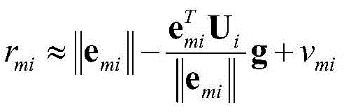
步骤三:对刚体运动后每个未知节点在全局参考坐标系中的坐标位置以模型方式进行描述,将si的模型描述为:si=Qci+t;然后对每个未知节点到各个锚节点的测量距离以模型方式进行描述,将rmi的模型描述为:rmi=||am-si||+vmi=||am-Qci-t||+vmi;接着对每个未知节点到各个锚节点的测量距离的模型描述进行形式整理,对于rmi=||am-si||+vmi=||am-Qci-t||+vmi,将等式rmi=||am-Qci-t||+vmi两边同时平方,忽略


步骤四:令F=ffT,使刚体定位问题的约束最小二乘表述形式中的约束条件QTQ=I等价于


步骤五:由于在步骤四中忽略了约束条件det(Q)=1,因此刚体定位问题的半正定规划形式关于Q的求解结果Qsdp并不准确,甚至不能满足旋转矩阵的性质,即可能出现


在此,对Qsdp进行正交化所采用的双重迭代算法为:
步骤六:对Qort和tsdp进行优化,得到Qort和tsdp各自的优化值,对应记为Qfin和tfin;将Qfin作为Q的最优估计值,将tfin作为t的最优估计值。Step 6: Optimizing Q ort and t sdp to obtain the respective optimized values of Q ort and t sdp , which are correspondingly recorded as Q fin and t fin ; take Q fin as the optimal estimated value of Q, and take t fin as the optimal value of t. best estimate.
在本实施例中,步骤六中对Qort和tsdp进行优化采用的优化方法为论文“J.Jiang,G.Wang,and K.C.Ho,``Accurate localization of a rigid body via semidefiniterelaxation,”IEEE Signal Process.Lett.,vol.25,no.3,pp,378-382,Mar.2018.”(蒋坚,王刚,K.C.Ho,“基于半正定规划的精确刚体定位,”IEEE Signal Process.Lett,第25卷,第3期,页码,378-382,三月,2018年)中公开的优化方法,步骤六的具体过程为:In this embodiment, the optimization method used to optimize Q ort and t sdp in step 6 is the paper "J.Jiang, G.Wang, and KCHo, "Accurate localization of a rigid body via semidefiniterelaxation," IEEE Signal Process .Lett., vol.25, no.3, pp, 378-382, Mar. 2018.” (Jian Jiang, Gang Wang, KCHo, “Accurate Rigid Body Localization Based on Positive Semidefinite Programming,” IEEE Signal Process. Lett, pp. 25 The optimization method disclosed in Volume,
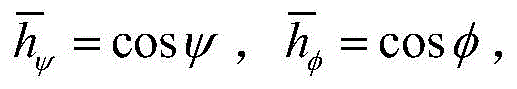
1)令Qfin表示Q的最优估计值,令tfin表示t的最优估计值;令Qfin=QortQδ,tfin=tsdp+Δt;如果Qδ满足旋转矩阵的性质,则Qfin也满足,因此在合理的假设Qδ中的欧拉角都接近于0的前提下,使用近似等式cosx≈1,sinx≈x,x为欧拉角,则得到Qδ的近似表达式为:


g=[βT,ΔtT]T,βT为β的转置,ΔtT为Δt的转置,[βT,ΔtT]T为[βT,ΔtT]的转置,


[||e11||v11,...,||eM1||vM1,||e12||v12,…,||eM2||vM2,…,||e1N||v1N,…,||eMN||vMN]T为[||e 11 ||v 11 , ..., ||e M1 ||v M1 , ||e 12 ||v 12 , ..., ||e M2 ||v M2 , ..., ||e 1N | |v 1N , …, ||e MN ||v MN ] T is
[||e11||v11,...,||eM1||vM1,||e12||v12,…,||eM2||vM2,…,||e1N||v1N,…,||eMN||vMN]的转置,


2)将


上述步骤六的过程是为了进一步提高定位精度,对已求得的Qort和tsdp进行优化。The process of the above-mentioned step 6 is to further improve the positioning accuracy and optimize the obtained Q ort and t sdp .
为了验证本发明方法的可行性和有效性,对本发明方法进行仿真试验。In order to verify the feasibility and effectiveness of the method of the present invention, a simulation test is carried out on the method of the present invention.
假设刚体的内部放置了N=5个未知节点,其相对于刚体的内部设置的局部参考坐标系的坐标位置分别为矩阵

测试本发明方法的性能随测量噪声标准差增加的变化情况。图3给出了本发明方法与现有的分拆各个击破的方法和现有的半正定规划方法的关于旋转矩阵Q的估计值与旋转矩阵Q的真实值的均方根误差随测量噪声标准差增加的变化图;图4给出了本发明方法与现有的分拆各个击破的方法和现有的半正定规划方法的关于位置矢量t的估计值与位置矢量t的真实值的均方根误差随测量噪声标准差增加的变化图。从图3和图4中可以看出,在无线传感器网络中锚节点分布比较差和无线传感器网络中噪声比较大的情况下,无论是关于Q,还是关于t的估计,本发明方法明显优于现有的分拆各个击破的方法,当测量噪声的功率在中等到较大的水平时,本发明方法对t的估计也优于现有的半正定规划方法,对Q的估计与现有的半正定规划方法性能接近,同时本发明方法的复杂度比现有的半正定规划方法低,足以说明本发明方法在刚体定位的精度方面有足够的优势。The performance of the method of the present invention was tested as a function of the increase in the standard deviation of the measurement noise. Fig. 3 shows the root mean square error of the estimated value of the rotation matrix Q and the real value of the rotation matrix Q with the measurement noise standard of the method of the present invention, the existing method of splitting each break and the existing positive semi-definite programming method Figure 4 shows the mean square of the estimated value of the position vector t and the real value of the position vector t of the method of the present invention and the existing splitting method and the existing positive semi-definite programming method. Plot of root error as the standard deviation of the measurement noise increases. It can be seen from Fig. 3 and Fig. 4 that under the condition that the distribution of anchor nodes in the wireless sensor network is relatively poor and the noise in the wireless sensor network is relatively large, the method of the present invention is obviously better than the estimation of Q or t. In the existing method of splitting each break, when the power of the measurement noise is at a medium to large level, the estimation of t by the method of the present invention is also better than the existing positive semi-definite programming method, and the estimation of Q is similar to the existing method. The performance of the positive semi-definite programming method is similar, and the complexity of the method of the present invention is lower than that of the existing positive semi-definite programming method, which is enough to show that the method of the present invention has sufficient advantages in the accuracy of rigid body positioning.
Claims (2)


Priority Applications (1)
| Application Number | Priority Date | Filing Date | Title |
|---|---|---|---|
| CN201810567164.0A CN108872935B (en) | 2018-06-05 | 2018-06-05 | Static rigid body positioning method based on distance measurement |
Applications Claiming Priority (1)
| Application Number | Priority Date | Filing Date | Title |
|---|---|---|---|
| CN201810567164.0A CN108872935B (en) | 2018-06-05 | 2018-06-05 | Static rigid body positioning method based on distance measurement |
Publications (2)
| Publication Number | Publication Date |
|---|---|
| CN108872935A CN108872935A (en) | 2018-11-23 |
| CN108872935B true CN108872935B (en) | 2020-11-10 |
Family
ID=64336561
Family Applications (1)
| Application Number | Title | Priority Date | Filing Date |
|---|---|---|---|
| CN201810567164.0A Active CN108872935B (en) | 2018-06-05 | 2018-06-05 | Static rigid body positioning method based on distance measurement |
Country Status (1)
| Country | Link |
|---|---|
| CN (1) | CN108872935B (en) |
Citations (5)
| Publication number | Priority date | Publication date | Assignee | Title |
|---|---|---|---|---|
| CN102186242A (en) * | 2011-05-09 | 2011-09-14 | 江南大学 | Method for positioning mobile node of wireless sensor network in fixed area |
| CN102841345A (en) * | 2011-06-22 | 2012-12-26 | 财团法人工业技术研究院 | Electronic device, positioning method and system, computer program product and recording medium |
| CN102890265A (en) * | 2012-08-09 | 2013-01-23 | 西北工业大学 | Passive target positioning method based on underwater acoustic sensor network |
| CN104050483A (en) * | 2014-06-25 | 2014-09-17 | 北京大学 | Feature dimension reduction method based on local orthogonal alignment |
| CN107015259A (en) * | 2016-01-27 | 2017-08-04 | 北京中联星通投资管理有限公司 | The tight integration method of pseudorange/pseudorange rates is calculated using Doppler anemometer |
-
2018
- 2018-06-05 CN CN201810567164.0A patent/CN108872935B/en active Active
Patent Citations (5)
| Publication number | Priority date | Publication date | Assignee | Title |
|---|---|---|---|---|
| CN102186242A (en) * | 2011-05-09 | 2011-09-14 | 江南大学 | Method for positioning mobile node of wireless sensor network in fixed area |
| CN102841345A (en) * | 2011-06-22 | 2012-12-26 | 财团法人工业技术研究院 | Electronic device, positioning method and system, computer program product and recording medium |
| CN102890265A (en) * | 2012-08-09 | 2013-01-23 | 西北工业大学 | Passive target positioning method based on underwater acoustic sensor network |
| CN104050483A (en) * | 2014-06-25 | 2014-09-17 | 北京大学 | Feature dimension reduction method based on local orthogonal alignment |
| CN107015259A (en) * | 2016-01-27 | 2017-08-04 | 北京中联星通投资管理有限公司 | The tight integration method of pseudorange/pseudorange rates is calculated using Doppler anemometer |
Non-Patent Citations (2)
| Title |
|---|
| Accurate Localization of a Rigid Body Using Multiple Sensors and Landmarks;Shanjie Chen 等;《IEEE TRANSACTIONS ON SIGNAL PROCESSING》;20151215;第63卷(第24期);6459-6472 * |
| 基于最小二乘测距定位算法信标最优部署模型;刘书静 等;《计算机学报》;20130331;第36卷(第3期);546-556 * |
Also Published As
| Publication number | Publication date |
|---|---|
| CN108872935A (en) | 2018-11-23 |
Similar Documents
| Publication | Publication Date | Title |
|---|---|---|
| Gramkow | On averaging rotations | |
| Zhao | An efficient solution to non-minimal case essential matrix estimation | |
| CN100461220C (en) | Calibration method based on fixed parameters and variable parameters in 3D scanning system | |
| CN104076332B (en) | A kind of radar uniform linear array amplitude and the method for estimation of phase place | |
| CN109471061B (en) | A Received Signal Strength Difference Location Method Robustly Handling Model Parameter Errors | |
| CN104615880B (en) | Rapid ICP (inductively coupled plasma) method for point cloud matching of three-dimensional laser radar | |
| CN113923590B (en) | A TOA positioning method under the condition of uncertain anchor node position | |
| CN104539340B (en) | A kind of sane direction of arrival estimation method being fitted based on rarefaction representation and covariance | |
| CN108668358A (en) | A Cooperative Positioning Method Based on Time of Arrival for Wireless Sensor Networks | |
| CN116088303B (en) | A Time-varying Recursive Estimation Method for Uncertain Complex Dynamic Network State | |
| Han et al. | A matching algorithm based on the nonlinear filter and similarity transformation for gravity-aided underwater navigation | |
| Liu et al. | A convex optimization based approach for pose SLAM problems | |
| CN108200547B (en) | Rigid body localization method based on measured distance | |
| CN107613458B (en) | The localization method of optimal joint time synchronization and positioning under the conditions of a kind of TDOA | |
| CN104181513A (en) | Array element position correcting method of radar antenna | |
| CN108872935B (en) | Static rigid body positioning method based on distance measurement | |
| CN103810747A (en) | Three-dimensional point cloud object shape similarity comparing method based on two-dimensional mainstream shape | |
| CN112533284B (en) | Near-far field unified positioning method based on arrival angle | |
| CN109031195B (en) | Mobile rigid body positioning method based on distance and Doppler measurement | |
| CN109738852A (en) | The distributed source two-dimensional space Power estimation method rebuild based on low-rank matrix | |
| CN109561384B (en) | A wireless sensor network node location method under complex noise conditions | |
| Ge et al. | Relative sensor registration with two‐step method for state estimation | |
| Baechler et al. | Combining range and direction for improved localization | |
| CN119415808B (en) | Particle swarm optimization algorithm-based wellbore separation coefficient calculation method | |
| Zhou et al. | Determining the robot-to-robot relative pose using range-only measurements |
Legal Events
| Date | Code | Title | Description |
|---|---|---|---|
| PB01 | Publication | ||
| PB01 | Publication | ||
| SE01 | Entry into force of request for substantive examination | ||
| SE01 | Entry into force of request for substantive examination | ||
| GR01 | Patent grant | ||
| GR01 | Patent grant |