CN108780680B - Electric wire for communication - Google Patents
Electric wire for communication Download PDFInfo
- Publication number
- CN108780680B CN108780680B CN201680083363.3A CN201680083363A CN108780680B CN 108780680 B CN108780680 B CN 108780680B CN 201680083363 A CN201680083363 A CN 201680083363A CN 108780680 B CN108780680 B CN 108780680B
- Authority
- CN
- China
- Prior art keywords
- wire
- sheath
- communication
- twisted pair
- conductor
- Prior art date
- Legal status (The legal status is an assumption and is not a legal conclusion. Google has not performed a legal analysis and makes no representation as to the accuracy of the status listed.)
- Active
Links
Images


Classifications
-
- H—ELECTRICITY
- H01—ELECTRIC ELEMENTS
- H01B—CABLES; CONDUCTORS; INSULATORS; SELECTION OF MATERIALS FOR THEIR CONDUCTIVE, INSULATING OR DIELECTRIC PROPERTIES
- H01B7/00—Insulated conductors or cables characterised by their form
- H01B7/02—Disposition of insulation
- H01B7/0291—Disposition of insulation comprising two or more layers of insulation having different electrical properties
-
- H—ELECTRICITY
- H01—ELECTRIC ELEMENTS
- H01B—CABLES; CONDUCTORS; INSULATORS; SELECTION OF MATERIALS FOR THEIR CONDUCTIVE, INSULATING OR DIELECTRIC PROPERTIES
- H01B11/00—Communication cables or conductors
- H01B11/02—Cables with twisted pairs or quads
-
- H—ELECTRICITY
- H01—ELECTRIC ELEMENTS
- H01B—CABLES; CONDUCTORS; INSULATORS; SELECTION OF MATERIALS FOR THEIR CONDUCTIVE, INSULATING OR DIELECTRIC PROPERTIES
- H01B11/00—Communication cables or conductors
- H01B11/002—Pair constructions
-
- H—ELECTRICITY
- H01—ELECTRIC ELEMENTS
- H01B—CABLES; CONDUCTORS; INSULATORS; SELECTION OF MATERIALS FOR THEIR CONDUCTIVE, INSULATING OR DIELECTRIC PROPERTIES
- H01B11/00—Communication cables or conductors
- H01B11/02—Cables with twisted pairs or quads
- H01B11/06—Cables with twisted pairs or quads with means for reducing effects of electromagnetic or electrostatic disturbances, e.g. screens
- H01B11/08—Screens specially adapted for reducing cross-talk
-
- H—ELECTRICITY
- H01—ELECTRIC ELEMENTS
- H01B—CABLES; CONDUCTORS; INSULATORS; SELECTION OF MATERIALS FOR THEIR CONDUCTIVE, INSULATING OR DIELECTRIC PROPERTIES
- H01B11/00—Communication cables or conductors
- H01B11/02—Cables with twisted pairs or quads
- H01B11/06—Cables with twisted pairs or quads with means for reducing effects of electromagnetic or electrostatic disturbances, e.g. screens
- H01B11/10—Screens specially adapted for reducing interference from external sources
-
- H—ELECTRICITY
- H01—ELECTRIC ELEMENTS
- H01B—CABLES; CONDUCTORS; INSULATORS; SELECTION OF MATERIALS FOR THEIR CONDUCTIVE, INSULATING OR DIELECTRIC PROPERTIES
- H01B11/00—Communication cables or conductors
- H01B11/02—Cables with twisted pairs or quads
- H01B11/12—Arrangements for exhibiting specific transmission characteristics
-
- H—ELECTRICITY
- H01—ELECTRIC ELEMENTS
- H01B—CABLES; CONDUCTORS; INSULATORS; SELECTION OF MATERIALS FOR THEIR CONDUCTIVE, INSULATING OR DIELECTRIC PROPERTIES
- H01B13/00—Apparatus or processes specially adapted for manufacturing conductors or cables
- H01B13/02—Stranding-up
-
- H—ELECTRICITY
- H01—ELECTRIC ELEMENTS
- H01B—CABLES; CONDUCTORS; INSULATORS; SELECTION OF MATERIALS FOR THEIR CONDUCTIVE, INSULATING OR DIELECTRIC PROPERTIES
- H01B7/00—Insulated conductors or cables characterised by their form
- H01B7/0009—Details relating to the conductive cores
-
- H—ELECTRICITY
- H01—ELECTRIC ELEMENTS
- H01B—CABLES; CONDUCTORS; INSULATORS; SELECTION OF MATERIALS FOR THEIR CONDUCTIVE, INSULATING OR DIELECTRIC PROPERTIES
- H01B7/00—Insulated conductors or cables characterised by their form
- H01B7/02—Disposition of insulation
-
- H—ELECTRICITY
- H01—ELECTRIC ELEMENTS
- H01B—CABLES; CONDUCTORS; INSULATORS; SELECTION OF MATERIALS FOR THEIR CONDUCTIVE, INSULATING OR DIELECTRIC PROPERTIES
- H01B7/00—Insulated conductors or cables characterised by their form
- H01B7/02—Disposition of insulation
- H01B7/0208—Cables with several layers of insulating material
- H01B7/0216—Two layers
-
- H—ELECTRICITY
- H01—ELECTRIC ELEMENTS
- H01B—CABLES; CONDUCTORS; INSULATORS; SELECTION OF MATERIALS FOR THEIR CONDUCTIVE, INSULATING OR DIELECTRIC PROPERTIES
- H01B7/00—Insulated conductors or cables characterised by their form
- H01B7/17—Protection against damage caused by external factors, e.g. sheaths or armouring
- H01B7/18—Protection against damage caused by wear, mechanical force or pressure; Sheaths; Armouring
Landscapes
- Physics & Mathematics (AREA)
- Electromagnetism (AREA)
- Engineering & Computer Science (AREA)
- Manufacturing & Machinery (AREA)
- Insulated Conductors (AREA)
- Communication Cables (AREA)
- Conductive Materials (AREA)
Abstract
提供一种在确保所需大小的特性阻抗值的同时细径化的通信用电线。通信用电线(1)具有:将由拉伸强度为400MPa以上的导体(12)以及包覆该导体(12)的外周的绝缘被覆(13)构成的一对绝缘电线(11、11)绞合而成的双绞线(10);以及由包覆双绞线(10)的外周的绝缘材料构成的护皮(30),在护皮(30)与构成双绞线(10)的绝缘电线(11)之间存在空隙(G),特性阻抗处于100±10Ω的范围。
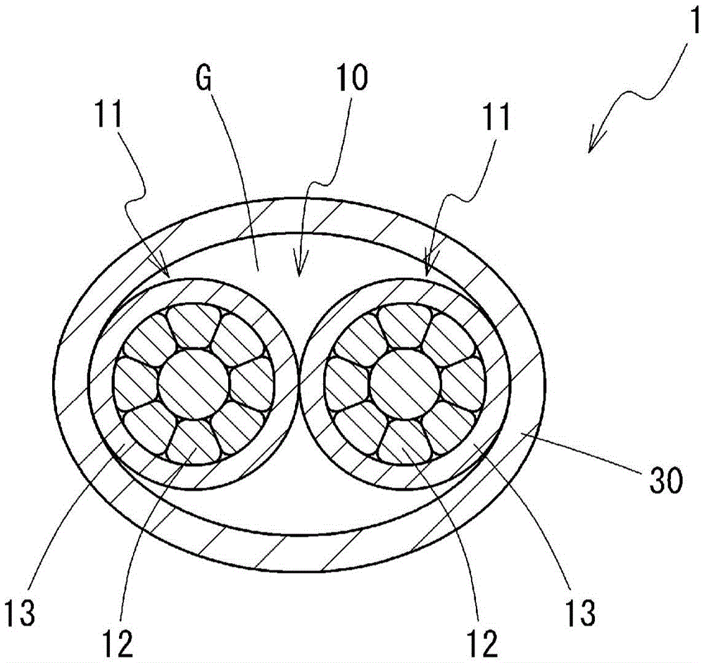
Provided is a communication wire with a reduced diameter while ensuring a desired characteristic impedance value. The communication wire (1) comprises: a twisted pair (10) formed by twisting a pair of insulated wires (11, 11) comprising a conductor (12) having a tensile strength of 400 MPa or more and an insulating sheath (13) covering the outer periphery of the conductor (12); and a sheath (30) made of an insulating material covering the outer periphery of the twisted pair (10), wherein a gap (G) exists between the sheath (30) and the insulated wires (11) constituting the twisted pair (10), and the characteristic impedance is within the range of 100±10Ω.
Description
技术领域technical field
本发明涉及一种通信用电线,更详细地说,涉及一种在汽车等中能够用于高速通信的通信用电线。The present invention relates to a communication wire, and more specifically, to a communication wire that can be used for high-speed communication in automobiles and the like.
背景技术Background technique
在汽车等领域中,高速通信的需求正在增加。在用于高速通信的电线中,需要严格地管理特性阻抗等传送特性。例如,在用于以太网通信的电线中,需要以特性阻抗为100±10Ω的方式进行管理。In fields such as automobiles, the demand for high-speed communication is increasing. In a wire used for high-speed communication, it is necessary to strictly manage transmission characteristics such as characteristic impedance. For example, in a wire used for Ethernet communication, it needs to be managed in such a way that the characteristic impedance is 100±10Ω.
通信用电线的特性阻抗取决于导体直径、绝缘被覆的种类、厚度等通信用电线的具体结构来决定。例如,在专利文献1中,公开了一种通信用屏蔽电线,构成为具备:将具备导体和包覆该导体的绝缘体的一对绝缘线芯绞合而成的双绞线;包覆该双绞线的屏蔽用的金属箔屏蔽部;与该金属箔屏蔽部导通的接地用电线;以及将它们整个包覆的护皮,并且,特性阻抗值为100±10Ω。在这里,作为绝缘线芯,使用导体直径为0.55mm的绝缘线芯,包覆导体的绝缘体的厚度为0.35~0.45mm。The characteristic impedance of the communication wire is determined by the specific structure of the communication wire, such as the diameter of the conductor, the type and thickness of the insulating coating, etc. For example,
现有技术文献prior art literature
专利文献Patent Literature
专利文献1:日本特开2005-32583号公报Patent Document 1: Japanese Patent Laid-Open No. 2005-32583
发明内容SUMMARY OF THE INVENTION
发明所要解决的课题The problem to be solved by the invention
在用于汽车等的通信用电线中,对于细径化的需求大。为了满足该需求,需要在满足特性阻抗等传送特性的同时,实现通信用电线的细径化。作为使具有双绞线的通信用电线细径化的方法,考虑使构成双绞线的绝缘电线的绝缘被覆变薄。但是,根据本发明者的试验,在专利文献1所记载的通信用电线中,如果使绝缘体的厚度小于0.35mm,则特性阻抗小于90Ω,偏离以太网通信所要求的100±10Ω的范围。In communication wires used in automobiles and the like, there is a great demand for diameter reduction. In order to meet this demand, it is necessary to reduce the diameter of the communication wire while satisfying transmission characteristics such as characteristic impedance. As a method of reducing the diameter of a communication wire having a twisted pair wire, it is considered to reduce the insulation coating of the insulated wire constituting the twisted pair wire. However, according to the experiments of the present inventors, in the communication wire described in
本发明的课题在于,提供一种在确保所需大小的特性阻抗值的同时细径化的通信用电线。An object of the present invention is to provide a communication wire with a reduced diameter while ensuring a characteristic impedance value of a desired magnitude.
用于解决课题的技术方案Technical solutions for solving problems
为了解决上述课题,本发明涉及一种通信用电线,其特征在于,具有:将由拉伸强度为400MPa以上的导体以及包覆该导体的外周的绝缘被覆构成的一对绝缘电线绞合而成的双绞线;以及由包覆所述双绞线的外周的绝缘材料构成的护皮,在所述护皮与构成所述双绞线的所述绝缘电线之间存在空隙。In order to solve the above-mentioned problems, the present invention relates to a communication wire, comprising: a pair of insulated wires formed by twisting a conductor having a tensile strength of 400 MPa or more and an insulating coating covering the outer periphery of the conductor. A twisted pair of wires; and a sheath made of an insulating material covering the outer periphery of the twisted pair of wires, with a gap between the sheath and the insulated wires constituting the twisted pair of wires.
在这里,所述绝缘电线的导体截面积优选小于0.22mm2。另外,所述绝缘电线的绝缘被覆的厚度优选为0.30mm以下。所述绝缘电线的外径优选为1.05mm以下。所述绝缘电线的导体的断裂伸长率优选为7%以上。Here, the conductor cross-sectional area of the insulated wire is preferably less than 0.22 mm 2 . Moreover, it is preferable that the thickness of the insulation coating of the said insulated wire is 0.30 mm or less. The outer diameter of the insulated wire is preferably 1.05 mm or less. The breaking elongation of the conductor of the insulated wire is preferably 7% or more.
在所述通信用电线的与轴交叉的剖面中,被所述护皮的外周缘包围的区域的面积中所述空隙所占的面积的比例优选为8%以上。在所述通信用电线的与轴交叉的剖面中,被所述护皮的外周缘包围的区域的面积中所述空隙所占的面积的比例优选为30%以下。所述双绞线的扭绞间距优选为所述绝缘电线的外径的45倍以下。所述护皮对所述绝缘电线的紧贴力优选为4N以上。It is preferable that the ratio of the area occupied by the void in the area of the area surrounded by the outer peripheral edge of the sheath in the cross section intersecting the axis of the communication wire is 8% or more. The ratio of the area occupied by the void in the area of the area surrounded by the outer peripheral edge of the sheath in the cross section intersecting the axis of the communication wire is preferably 30% or less. The twist pitch of the twisted pair is preferably 45 times or less the outer diameter of the insulated wire. The adhesion force of the sheath to the insulated wire is preferably 4N or more.
发明效果Invention effect
在上述发明的通信用电线中,构成双绞线的绝缘电线的导体具有400MPa以上的高的拉伸强度,所以,能够在确保作为电线所需的强度的同时,减小导体直径。于是,构成双绞线的2根导体之间的距离变小,从而能够使通信用电线的特性阻抗变高。其结果为,即使为了实现通信用电线的细径化而使绝缘电线的绝缘被覆变薄,也能够确保特性阻抗不小于100±10Ω的范围。In the communication wire of the invention described above, the conductor of the insulated wire constituting the twisted pair has a high tensile strength of 400 MPa or more, so the conductor diameter can be reduced while securing the strength required for the wire. Accordingly, the distance between the two conductors constituting the twisted pair is reduced, and the characteristic impedance of the communication wire can be increased. As a result, even if the insulating coating of the insulated wire is made thinner in order to reduce the diameter of the communication wire, the characteristic impedance can be ensured in a range of not less than 100±10Ω.
进一步地,在包覆双绞线的外周的护皮与构成双绞线的绝缘电线之间存在空隙,在双绞线的周围存在空气层,从而与以充实状态形成护皮的情况相比,能够使通信用电线的特性阻抗变高。因此,即使使绝缘电线的绝缘被覆的厚度变小,也容易维持作为通信用电线的特性阻抗足够高的值。如果能够减小绝缘电线的绝缘被覆的厚度,则能够减小通信用电线整体的外径。Furthermore, there is a gap between the sheath covering the outer circumference of the twisted pair and the insulated wire constituting the twisted pair, and an air layer exists around the twisted pair, so that compared with the case where the sheath is formed in a solid state, The characteristic impedance of the communication wire can be increased. Therefore, even if the thickness of the insulating coating of the insulated wire is reduced, it is easy to maintain a sufficiently high value for the characteristic impedance of the communication wire. If the thickness of the insulating coating of the insulated wire can be reduced, the outer diameter of the entire communication wire can be reduced.
在这里,在绝缘电线的导体截面积小于0.22mm2的情况下,由于构成双绞线的2根绝缘电线之间的距离变近的效果,特性阻抗变高,所以,容易在维持所需的特性阻抗的同时,通过使绝缘被覆变薄而进行通信用电线的细径化。另外,导体的粗细度自身也对通信用电线的细径化具有效果。Here, when the conductor cross-sectional area of the insulated wire is less than 0.22 mm 2 , the characteristic impedance becomes high due to the effect of shortening the distance between the two insulated wires constituting the twisted pair, so it is easy to maintain the required In addition to the characteristic impedance, the diameter of the communication wire is reduced by thinning the insulating coating. In addition, the thickness of the conductor itself also has an effect on reducing the diameter of the communication wire.
另外,在绝缘电线的绝缘被覆的厚度为0.30mm以下的情况下,使绝缘电线充分地细径化,从而容易使通信用电线整体细径化。In addition, when the thickness of the insulating coating of the insulated wire is 0.30 mm or less, the diameter of the insulated wire is sufficiently reduced, and the diameter of the entire communication wire can be easily reduced.
在绝缘电线的外径为1.05mm以下的情况下,也容易使通信用电线整体细径化。Even when the outer diameter of the insulated wire is 1.05 mm or less, it is easy to reduce the diameter of the entire communication wire.
在绝缘电线的导体的断裂伸长率为7%以上的情况下,导体的耐冲击性变高,在进行通信用电线向导线线束的加工时,容易经受住在导线线束的组装等时候施加于导体的冲击。When the breaking elongation of the conductor of the insulated wire is 7% or more, the impact resistance of the conductor becomes high, and when processing the wire for communication into the wire harness, it is easy to withstand the application of the wire harness when assembling the wire harness. impact of conductors.
当在通信用电线的与轴交叉的剖面中被护皮的外周缘包围的区域的面积中空隙所占的面积的比例为8%以上的情况下,提高通信用电线的特性阻抗,从而减小通信用电线的外径的效果特别优异。When the ratio of the area occupied by the void to the area of the area surrounded by the outer peripheral edge of the sheath in the cross-section intersecting the axis of the communication wire is 8% or more, the characteristic impedance of the communication wire is increased and reduced The effect of the outer diameter of the communication wire is particularly excellent.
当在通信用电线的与轴交叉的剖面中被护皮的外周缘包围的区域的面积中空隙所占的面积的比例为30%以下的情况下,容易防止由于空隙过大而在护皮的内部空间中双绞线的位置不确定、通信用电线的特性阻抗、各种传送特性发生偏差、时变的情况。When the ratio of the area occupied by the void to the area of the area surrounded by the outer peripheral edge of the sheath in the cross section intersecting the axis of the communication wire is 30% or less, it is easy to prevent the sheath from being too large due to the void. The position of the twisted pair in the internal space is uncertain, the characteristic impedance of the communication wire, and various transmission characteristics vary and change over time.
在双绞线的扭绞间距为绝缘电线的外径的45倍以下的情况下,不易引起双绞线的扭绞构造的松弛,容易防止由于扭绞构造的松弛而通信用电线的特性阻抗、各种传送特性发生偏差、时变的情况。When the twist pitch of the twisted pair is 45 times or less the outer diameter of the insulated wire, the slack in the twist structure of the twisted pair is unlikely to occur, and it is easy to prevent the characteristic impedance, When various transmission characteristics deviate and change over time.
在护皮对绝缘电线的紧贴力为4N以上的情况下,能防止出现双绞线相对于护皮的位置偏移、双绞线扭绞构造的松弛,从而容易防止通信用电线的特性阻抗、各种传送特性由于这些影响而发生偏差、经时变化。When the adhesion force of the sheath to the insulated wire is 4N or more, the positional deviation of the twisted pair relative to the sheath and the slack of the twisted structure of the twisted pair can be prevented, and the characteristic impedance of the communication wire can be easily prevented , Due to these influences, various transmission characteristics deviate and change with time.
附图说明Description of drawings
图1是示出本发明的一个实施方式的通信用电线的剖视图,护皮被设置为宽松封套。FIG. 1 is a cross-sectional view showing a communication wire according to an embodiment of the present invention, and the sheath is provided as a loose cover.
图2是示出作为护皮被设置为充实封套的通信用电线的剖视图。FIG. 2 is a cross-sectional view showing a communication wire provided as a sheath as a substantial envelope.
图3是关于双绞线说明2种扭绞构造的图,(a)示出第一扭绞构造(无扭转)、(b)示出第二扭绞构造(有扭转)。在图中,虚线是沿着绝缘电线的轴示出以绝缘电线的轴为中心位于相同位置的部位的引导。3 is a diagram illustrating two types of twist structures about a twisted pair wire, wherein (a) shows a first twist structure (without twist), and (b) shows a second twist structure (with twist). In the figure, a broken line is a guide showing a portion located at the same position with the axis of the insulated electric wire as the center along the axis of the insulated electric wire.
图4是关于护皮是宽松封套的情况以及是充实封套的情况而示出绝缘电线的绝缘被覆的厚度与特性阻抗的关系的图。还一起示出关于不设置护皮的情况的模拟结果。FIG. 4 is a diagram showing the relationship between the thickness of the insulating coating of the insulated wire and the characteristic impedance for a case where the sheath is a loose cover and a case where the sheath is a solid cover. The simulation results for the case where no skins are provided are also shown together.
具体实施方式Detailed ways
下面,使用附图来详细说明本发明的一个实施方式的通信用电线。Hereinafter, a communication wire according to an embodiment of the present invention will be described in detail with reference to the drawings.
[通信用电线的结构][Structure of communication wires]
在图1中示出本发明的一个实施方式的通信用电线1的剖视图。FIG. 1 shows a cross-sectional view of a
通信用电线1具有将一对绝缘电线11、11绞合而成的双绞线10。各绝缘电线11具有导体12以及包覆导体12的外周的绝缘被覆13。并且,通信用电线1具有包覆双绞线10整体的外周而由绝缘材料构成的护皮30。The
通信用电线1具有100±10Ω的范围的特性阻抗。100±10Ω的特性阻抗是以太网通信用的电线所要求的值。通信用电线1具有这样的特性阻抗,从而能够在汽车等中适当地用于高速通信。The
(1)绝缘电线的结构(1) Structure of insulated wire
构成双绞线10的绝缘电线11的导体12由具有400MPa以上的拉伸强度的金属线材构成。作为具体的金属线材,能够例示出后面说明的含有Fe和Ti的铜合金线、以及含有Fe和P、Sn的铜合金线。导体12的拉伸强度如果是440MPa以上、进一步地是480MPa以上则更优选。The
导体12具有400MPa以上、进一步地具有440MPa以上、480MPa以上的拉伸强度,从而即使细径化,也能够维持作为电线所要求的拉伸强度。通过使导体12细径化,从而构成双绞线10的2根导体12、12之间的距离(连接导体12、12的中心的距离)变近,通信用电线1的特性阻抗变大。例如能够使导体12细径化至导体截面积小于0.22mm2、进一步地小于0.15mm2以下、0.13mm2以下的程度。作为导体12的外径,能够设为0.55mm以下、进一步地设为0.50mm以下、0.45mm以下。此外,如果使导体12过度地细径化,则难以维持强度,并且,通信用电线1的特性阻抗变得过大,所以,导体截面积优选设为0.08mm2以上。The
在导体12具有小于0.22mm2的小的导体截面积的情况下,即使使包覆导体12的外周的绝缘被覆13的厚度薄到例如0.30mm以下,在通信用电线1中,也容易确保100±10Ω的特性阻抗。此外,在以往的一般的铜电线的情况下,由于拉伸强度低,从而难以使导体截面积低于0.22mm2来使用。When the
导体12优选具有7%以上的断裂伸长率。一般来说,拉伸强度高的导体的韧性低、在急剧地施加力时的耐冲击性低的情况较多。但是,如上所述,在具有400MPa以上的高的拉伸强度的导体12中,如果具有7%以上的断裂伸长率,则在由通信用电线1装配导线线束的工序、以及该导线线束的组装的工序中,即使对导体12施加冲击,导体12也能够发挥高的耐冲击性。导体12的断裂伸长率如果为10%以上,则更优选。The
导体12也可以由单线构成,但从提高弯曲性等观点出发,优选由将多根线料绞合而成的绞线构成。在该情况下,也可以在将线料绞合之后,进行压缩成形,做成压缩绞线。通过压缩成形,能够缩小导体12的外径。另外,在导体12由绞线构成的情况下,如果作为导体12整体而具有400MPa以上的拉伸强度,则既可以全部由相同的线料构成,也可以由2种以上的线料构成。作为使用2种以上的线料的方式,能够例示出使用后面说明的由含有Fe和Ti的铜合金或者含有Fe和P、Sn的铜合金构成的线料以及由SUS等铜合金以外的金属材料构成的线料的情况。The
绝缘电线11的绝缘被覆13可以由任何绝缘性的聚合物材料构成。从作为特性阻抗而确保预定的高的值的观点出发,绝缘被覆13优选具有4.0以下的相对介电常数。作为这样的聚合物材料,能够列举聚乙烯、聚丙烯等聚烯烃、聚氯乙烯、聚苯乙烯、聚四氟乙烯、聚苯硫醚等。除了聚合物材料之外,绝缘电线11还可以适当地含有阻燃剂等添加剂。The insulating
在通信用电线1中,由于通过使导体12细径化、导体12、12间的接近而使特性阻抗上升的效果,能够减小确保预定的特性阻抗所需的绝缘被覆13的厚度。例如,优选将绝缘被覆13的厚度设为0.30mm以下、进一步地设为0.25mm以下、0.20mm以下。此外,如果使绝缘被覆13变得过薄,则难以确保所需的大小的特性阻抗,所以,优选将绝缘被覆13的厚度设为大于0.15mm。In the
通过导体12的细径化以及绝缘被覆13的薄层化,使绝缘电线11整体细径化。例如,能够将绝缘电线11的外径设为1.05mm以下、进一步地设为0.95mm以下、进而0.85mm以下。通过使绝缘电线11细径化,从而能够使通信用电线1整体细径化。By reducing the diameter of the
在绝缘电线11中,在导体12的整周上绝缘被覆13的厚度(绝缘厚度)的均匀性高为优选。即,厚度不均较小为优选。于是,导体12的偏芯变小,在构成双绞线10时,导体12在双绞线10中所占的位置的对称性变高。其结果为,能够提高通信用电线1的传送特性、特别是模式转换特性。例如,优选将各绝缘电线11的偏芯率设为65%以上、更优选地设为75%以上。在这里,将偏芯率作为[最小绝缘厚度]/[最大绝缘厚度]×100%来计算。In the
(2)双绞线的扭绞构造(2) Twisted structure of twisted pair
双绞线10能够通过将2根绝缘电线11绞合而形成,扭绞间距能够根据绝缘电线11的外径等而设定。但是,通过将扭绞间距设为绝缘电线11的外径的60倍以下,优选设为45倍以下,更优选设为30倍以下,从而能够有效地抑制扭绞构造的松弛。扭绞构造的松弛可能导致通信用电线1的特性阻抗、各种传送特性的偏差、经时变化。特别是如后所述,在将护皮30设为宽松封套型的情况下,在护皮30与双绞线10之间存在空隙G,从而与设为充实封套型的情况相比,在双绞线10中使扭绞构造松弛的力起作用时,有时难以通过护皮30来抑制该情形,但通过选择上述扭绞间距,从而在使用宽松封套型的护皮30的情况下,也能够有效地抑制扭绞构造的松弛。通过抑制扭绞构造的松弛,从而能够将构成双绞线10的2根绝缘电线11之间的距离(线间距离)在间距内的各部位处维持为小的值、例如实质上维持为0mm,得到稳定的传送特性。另一方面,如果使双绞线10的扭绞间距变得过小,则双绞线10的生产率变低,制造成本上升,所以,扭绞间距优选设为绝缘电线11的外径的8倍以上、更优选设为12倍以上、15倍以上。The
在双绞线10中,作为2根绝缘电线11的扭绞构造,能够例示出以下的2个构造。在第一扭绞构造中,如图3(a)所示,在各绝缘电线11处,不附加以绞合轴为中心的扭转构造,以绝缘电线11自身的轴为中心的绝缘电线11的各部的相对的上下左右的方向不沿着绞合轴而变化。即,以绝缘电线11的轴为中心位于相同位置的部位在扭绞构造的整个区域中,始终朝向例如上方等相同方向。在图中,沿着绝缘电线11的轴用虚线表示以绝缘电线11的轴为中心位于相同位置的部位,与未附加扭转构造的情况对应地,在纸面近前侧的中心始终能看见该虚线。此外,在图3(a)、(b)中,为了容易观察,在使双绞线10的扭绞构造松弛的状态下显示。In the
另一方面,在第二扭绞构造中,如图3(b)所示,在各绝缘电线11处,以绞合轴为中心而附加扭转构造,以绝缘电线11自身的轴为中心的绝缘电线11的各部的相对的上下左右的方向沿着绞合轴变化。即,使以绝缘电线11的轴为中心位于相同位置的部位在扭绞构造中所朝向的方向上下左右地变化。在图中,沿着绝缘电线11的轴用虚线表示以绝缘电线11的轴为中心位于相同位置的部位,与附加扭转构造的情况对应地,该虚线仅在扭绞构造的1个间距内的一部分区域在纸面近前侧看得到,在扭绞构造的1个间距内,使其位置相对于纸面前后地连续变化。On the other hand, in the second twisted structure, as shown in FIG. 3( b ), each
优选采用上述2个扭绞构造中的第一扭绞构造。这是由于,在第一扭绞构造的情况下,在扭绞构造的1个间距内,2根绝缘电线11的线间距离的变化较小。特别是,在本实施方式的通信用电线1中,由于使绝缘电线11细径化,从而会因为扭绞的影响使得线间距离容易变化,但通过采用第一扭绞构造,从而能够将其影响抑制得较小。如果线间距离变化,则通信用电线1的传送特性容易不稳定化。It is preferable to employ the first twisted structure among the above-mentioned two twisted structures. This is because, in the case of the first twisted structure, within one pitch of the twisted structure, the change in the distance between the wires of the two
构成双绞线10的2根绝缘电线11的长度之差(线长差)较小为优选。在双绞线10中,能够提升2根绝缘电线11的对称性,能够提高传送特性、特别是模式转换特性。例如,如果将双绞线每1m的线长差抑制为5mm以下、更优选抑制为3mm以下,则容易将线长差的影响抑制得较小。It is preferable that the difference between the lengths of the two
(3)护皮的概略(3) Outline of skin care
护皮30是出于保护双绞线10、保持扭绞构造等目的而设置的。在图1的实施方式中,护皮30被设置为宽松封套,在成形为中空筒状的空间中,收容有双绞线10。护皮30沿着内周面的周向,仅在一部分区域与构成双绞线10的绝缘电线11接触,在除此以外的区域中,在护皮30与绝缘电线11之间存在空隙G,形成有空气层。关于护皮30的结构的详细情况,在后面叙述。The
此外,在评价在护皮30与绝缘电线11之间有没有空隙G以及后述的空隙G的比例等通信用电线1的剖面的状态时,为了避免由于用于形成剖面的切断操作而使护皮30、双绞线10发生变形而妨碍准确的评价,优选将通信用电线1整体包埋于丙烯酸等树脂中,在使该树脂浸透至护皮30的内部的空间的状态下固定之后,进行切断操作。在切剖面上,存在丙烯酸树脂的区域为原本是空隙G的区域。In addition, when evaluating the state of the cross-section of the
在本实施方式的通信用电线1中,与专利文献1的情况不同,在护皮30的内侧,不设置由包围双绞线20的导电性材料构成的屏蔽部,护皮30直接包围双绞线10的外周。屏蔽部对于双绞线10,起到遮蔽噪声从外部侵入以及噪声向外部放出的作用,但本实施方式的通信用电线1设想在噪声的影响不严重的条件下使用,未设置有屏蔽部。在本实施方式的通信用电线1中,根据有效地达成由结构的简化带来的细径化和低成本化的观点,在护皮30与双绞线20之间,除了不具有屏蔽部以外,也不具有其他部件,护皮30优选隔着空隙G直接包覆双绞线20的外周。In the
(4)通信用电线整体的特性(4) Characteristics of the entire communication wire
如上所述,在本通信用电线1中,构成双绞线10的绝缘电线11的导体12具有400MPa以上的拉伸强度,从而即使使导体12细径化,也容易维持作为汽车用电线而足够的强度。通过使导体12细径化,从而构成双绞线10的2根导体12、12之间的距离变近。如果2根导体12、12之间的距离变近,则通信用电线1的特性阻抗变高。如果构成双绞线10的绝缘电线11的绝缘被覆13的层变薄,则特性阻抗变小,但在本通信用电线1中,利用导体12、12的伴随着细径化的接近的效果,即使使绝缘被覆13的厚度减小到例如0.30mm以下,在通信用电线1中,也能够确保100±10Ω这样的特性阻抗。As described above, in the
通过使绝缘电线11的绝缘被覆13变薄,从而能够使作为通信用电线1整体的线径(成品直径)变细。例如,能够将通信用电线1的线径设为2.9mm以下、进一步地设为2.5mm以下。通过使通信用电线1在保持预定的特性阻抗值的同时细径化,从而能够将通信用电线1适当地用于汽车内等空间有限的场所中的高速通信的用途上。By thinning the insulating
构成绝缘电线11的导体12的细径化以及绝缘被覆13的薄壁化不仅对通信用电线1的细径化有效果,对通信用电线1的轻质化也有效果。通过使通信用电线1轻质化,从而例如在将通信用电线1用于汽车内的通信时,能够使车辆整体轻质化,带来车辆的低油耗化。The reduction of the diameter of the
另外,构成绝缘电线11的导体12具有400MPa以上的拉伸强度,从而通信用电线1具有高的断裂强度。例如,能够将断裂强度设为100N以上、进一步地设为140N以上。通信用电线1具有高的断裂强度,从而在终端处,针对端子等能够示出高的抓持力。即,容易防止在终端安装有端子等的部位处的通信用电线1的断裂。In addition, the
进一步地,在通信用电线中,期望除了具有100±10Ω这样足够大的特性阻抗之外,还使特性阻抗以外的传送特性、即透射损失(IL)、反射损失(RL)、透射模式转换(LCTL)、反射模式转换(LCL)那样的传送特性也满足预定的标准。在本实施方式的通信用电线1中,特别是,护皮30具有宽松封套型的结构,从而即使将绝缘电线11的绝缘被覆13设为小于0.25mm、进一步地设为0.15mm以下,也能够满足IL≤0.68dB/m(66MHz)、RL≥20.0dB(20MHz)、LCTL≥46.0dB(50MHz)、LCL≥46.0dB(50MHz)的标准。Furthermore, in the communication wire, in addition to having a sufficiently large characteristic impedance of 100±10Ω, it is desirable to make transmission characteristics other than the characteristic impedance, that is, transmission loss (IL), reflection loss (RL), transmission mode conversion ( Transmission characteristics such as LCTL) and reflection mode switching (LCL) also satisfy predetermined standards. In the
[护皮的详细结构][Detailed structure of the leather guard]
如上所述,在本实施方式中,护皮30被设置为宽松封套,在护皮30与构成双绞线10的绝缘电线11之间存在空隙G。另一方面,如图2所示,还能够考虑将护皮30’设置为充实封套的方式的通信用电线1’。在该情况下,护皮30’接触到构成双绞线10的绝缘电线11,或者充实状地形成至其非常接近的旁边的位置,在护皮30’与绝缘电线11之间,除了在制造上无法避免地形成的空隙以外,实质上不存在空隙。As described above, in the present embodiment, the
从在将特性阻抗保持于预定的高的标准的同时使通信用电线1细径化的观点出发,与护皮30是充实封套的情况相比,在是宽松封套的情况下更适当。通信用电线1的特性阻抗在双绞线10被介电常数低的材料包围的情况下变高(参照后面的式(1)),在双绞线10的周围存在空气层的宽松封套的结构与在双绞线10的外侧非常接近地存在电介体的充实封套的情况相比,能够使特性阻抗变高。因此,在宽松封套的情况下,即使使各绝缘电线11的绝缘被覆13变薄,也能够确保100±10Ω的特性阻抗。通过使绝缘被覆13变薄,从而使绝缘电线11细径化,通信用电线1整体的外径也能够减小。From the viewpoint of reducing the diameter of the
具体来说,如上所述,作为绝缘电线11的导体12而使用拉伸强度400MPa的导体,作为护皮30而使用宽松封套型的护皮,从而即使将绝缘电线11的绝缘被覆13的厚度设为小于0.25mm、进一步地设为0.20mm以下,在通信用电线1中,也能够确保100±10Ω的特性阻抗。在该情况下,能够将通信用电线1整体的外径设为2.5mm以下。Specifically, as described above, a conductor with a tensile strength of 400 MPa is used as the
另外,在使用宽松封套的情况下,用作护皮30的材料的量较少,从而与使用充实封套的情况相比,能够减小通信用电线1的每单位长度的质量。通过这样使护皮30轻质化,从而与上述的导体12的细径化以及绝缘被覆13的薄壁化的效果互相结合,能够有助于作为通信用电线1整体的轻质化,进而有助于用于汽车时的低油耗化。In addition, in the case of using the loose cover, the amount of material used as the
此外,在使用宽松封套型的护皮30的情况下,由于护皮30是中空筒形状,从而作为通信用电线1整体,容易受到预料不到的挠曲、弯曲的影响,但作为导体12而使用拉伸强度400MPa以上的导体,从而能够弥补该情形。In addition, in the case of using the loose
护皮30与绝缘电线11之间的空隙G越大,则有效介电常数(参照下述式(1))越小,通信用电线1的特性阻抗越大。如果在通信用电线1的与轴大致垂直交叉的剖面中,在被护皮30的外周缘包围的整个区域的面积即护皮30的厚度也包括在内的截面积中,使空隙G所占的面积的比例(外周面积率)为8%以上,则在双绞线10的周围存在足够的空气层,容易确保100±10Ω的特性阻抗。如果空隙G的外周面积率为15%以上,则更优选。另一方面,使空隙G所占的面积的比例过大,容易发生护皮30的内部空间中的双绞线10的位置偏移、双绞线10的扭绞构造的松弛。这些现象会导致通信用电线1的特性阻抗、各种传送特性的偏差、经时变化。从抑制这些情形的观点出发,空隙G的外周面积率优选抑制为30%以下,更优选抑制为23%以下。The larger the gap G between the
作为表示空隙G的比例的指标,代替上述外周面积率,还能够使用在通信用电线1的与轴大致垂直交叉的剖面中在被护皮30的内周缘包围的区域的面积即不包括护皮30的厚度的截面积中空隙G所占的面积的比例(内周面积率)。根据与在上面关于外周面积率所记载的理由相同的理由,空隙G的内周面积率优选为26%以上、更优选为39%以上。另一方面,内周面积率优选抑制为56%以下,更优选抑制为50%以下。护皮30的厚度也对通信用电线1的有效介电常数以及特性阻抗造成影响,所以,作为用于确保足够的特性阻抗的指标,与内周面积率相比,优选将外周面积率作为指标来设定空隙G。但是,特别是在护皮30厚的情况下,护皮30的厚度对通信用电线1的特性阻抗造成的影响变小,所以,内周面积率也成为好的指标。As an index showing the ratio of the gap G, instead of the above-mentioned outer peripheral area ratio, the area of the area surrounded by the inner periphery of the
剖面中的空隙G的比例在双绞线10的1个间距内的各部位处,也有时不恒定。在这样的情况下,关于空隙G的外周面积率以及内周面积率,作为双绞线10的1个间距的量的长度区域的平均值,满足上述条件为优选,如果在1个间距的量的长度区域的整个区域中满足上述条件,则更优选。或者,在这样的情况下,优选将双绞线10的1个间距的量的长度区域中的体积作为指标来评价空隙G的比例。即,在双绞线10的1个间距的量的长度区域中,优选将在被护皮30的外周面包围的区域的体积中空隙G所占的体积的比例(外周体积率)设为7%以上、更优选设为14%以上。另外,优选将外周体积率设为29%以下、更优选设为22%以下。或者,在双绞线10的1个间距的量的长度区域中,优选将在被护皮30的内周面包围的区域的体积中空隙G所占的体积的比例(内周体积率)设为25%以上、更优选设为38%以上。另外,优选将内周体积率设为55%以下、更优选设为49%以下。The ratio of the gap G in the cross section may not be constant at each location within one pitch of the
另外,如上所述,护皮30与绝缘电线11之间的空隙G越大,则由下述的式1表示的有效介电常数越小。有效介电常数除了取决于空隙G的大小之外,还取决于护皮30的材质以及厚度等参数,以使有效介电常数为7.0以下、更优选为6.0以下的方式,选择空隙G的大小以及其他参数,从而容易使通信用电线1的特性阻抗提高至100±10Ω的区域。另一方面,从通信用电线1的制造性、电线可靠性的观点、以及确保一定以上的绝缘被覆厚度的观点出发,有效介电常数优选为1.5以上、更优选为2.0以上。空隙G的大小能够根据通过挤压成形来制作护皮30时的条件(冲模、点形状、挤压温度等)而进行控制。In addition, as described above, the larger the gap G between the
[式1][Formula 1]

在这里,εeff是有效介电常数、d是导体直径、D是电线外径、η0是常数。Here, ε eff is the effective dielectric constant, d is the conductor diameter, D is the wire outer diameter, and η 0 is a constant.
如图1所示,护皮30在内周面的一部分区域中,与绝缘电线11接触。在这些区域中,如果护皮30牢固地紧贴于绝缘电线11,则由护皮30压住双绞线10,从而能够抑制护皮30的内部空间中的双绞线10的位置偏移、双绞线10的扭绞构造的松弛那样的现象。如果将护皮30对绝缘电线11的紧贴力设为4N以上、更优选设为7N以上、以及8N以上,则会抑制这些现象,将2根绝缘电线11的线间距离维持为小的值、例如实质上维持为0mm,从而能够有效地抑制特性阻抗、各种传送特性的偏差、经时变化。另一方面,护皮30的紧贴力过大,通信用电线1的加工性也变差,所以,紧贴力优选抑制为70N以下。护皮30对绝缘电线11的紧贴性在通过树脂材料的挤压而将护皮30形成于双绞线10的外周时,能够通过改变树脂材料的挤压温度来调整。紧贴力例如能够作为如下强度来评价:在全长150mm的通信用电线1中,在从一端去除了30mm的护皮30的状态下,将双绞线10拉伸,直至双绞线10脱落为止。As shown in FIG. 1 , the
另外,绝缘电线11与护皮30的内周面接触的区域的面积越大,则越容易抑制护皮30的内部空间中的双绞线10的位置偏移、双绞线10的扭绞构造的松弛那样的现象。在通信用电线1的与轴大致垂直交叉的剖面中,如果将护皮30的内周缘的全长中的与绝缘电线11接触的部位的长度(接触率)设为0.5%以上、更优选设为2.5%以上,则能够有效地抑制这些现象。另一方面,如果将接触率设为80%以下、更优选设为50%以下,则容易确保空隙G。关于接触率,作为双绞线10的1个间距的量的长度区域的平均值,满足上述条件为优选,如果在1个间距的量的长度区域的整个区域中满足上述条件,则更优选。In addition, the larger the area of the area where the
护皮30的厚度适当选择即可。例如,从降低来自通信用电线1的外部的噪声的影响例如在将通信用电线1与其他电线一起在导线线束等的状态下使用时来自其他电线的影响的观点、以及确保耐磨损性、耐冲击性等护皮30的机械特性的观点出发,将护皮的厚度设为0.20mm以上、更优选设为0.30mm以上即可。另一方面,如果考虑将有效介电常数抑制得较小、使通信用电线1整体细径化,则将护皮30的厚度设为1.0mm以下、更优选设为0.7mm以下即可。The thickness of the
如上所述,从通信用电线1的细径化的观点出发,优选使用宽松封套型的护皮30,但在细径化的要求不那么大的情况等下,如图2所示,还考虑使用充实封套型的护皮30’。在充实型的护皮30’的情况下,能够用护皮30’更牢固地固定双绞线10,容易防止双绞线10相对于护皮30’的位置偏移、扭绞构造的松弛等现象。其结果为,容易防止由于这些现象而使通信用电线1的特性阻抗、各种传送特性发生经时变化、偏差。能够根据通过挤压成形而制作护皮时的条件(冲模、点形状、挤压温度等)来控制设为宽松封套型的护皮30与充实封套型的护皮30’中的哪一方。另外,当在双绞线10的保护、扭绞构造的保持上不产生问题的状况下,能够省略护皮30,并非必须设置于通信用电线。As described above, from the viewpoint of reducing the diameter of the
护皮30与绝缘电线11的绝缘被覆13同样地,可以由任何聚合物材料构成。即,作为聚合物材料,能够列举聚乙烯、聚丙烯等聚烯烃、聚氯乙烯、聚苯乙烯、聚四氟乙烯、聚苯硫醚等。在这些材料当中,从增大通信用电线1的特性阻抗的观点出发,特别优选使用作为非极性的聚合物材料的聚烯烃。除了聚合物材料之外,护皮30还可以适当地含有阻燃剂等添加剂。另外,护皮30也可以由多个层构成,但从由结构的简化带来的通信用电线1的细径化和低成本化的观点出发,护皮30优选仅由1层构成。The
[导体的材料][material of conductor]
在这里,说明在上述实施方式的通信用电线1中作为绝缘电线11的导体12的具体例的铜合金线。Here, a copper alloy wire as a specific example of the
在这里作为第一例列举的铜合金线具有如下成分组成。The copper alloy wire listed here as the first example has the following composition.
·Fe:0.05质量%以上、2.0质量%以下Fe: 0.05 mass % or more and 2.0 mass % or less
·Ti:0.02质量%以上、1.0质量%以下Ti: 0.02 mass % or more and 1.0 mass % or less
·Mg:0质量%以上、0.6质量%以下(还包括不含有Mg的方式)Mg: 0 mass % or more and 0.6 mass % or less (the form not containing Mg is also included)
·剩余部分由Cu以及无法避免的杂质构成。• The remainder consists of Cu and unavoidable impurities.
具有上述组成的铜合金线具有非常高的拉伸强度。其中,在Fe的含量为0.8质量%以上的情况下,并且在Ti的含量为0.2质量%以上的情况下,能够达成特别高的拉伸强度。特别是,通过提高拉丝加工度、使线径变细、在拉丝后进行热处理,能够提高拉伸强度,能够得到具有400MPa以上的拉伸强度的导体11。The copper alloy wire having the above-mentioned composition has very high tensile strength. Among them, when the Fe content is 0.8 mass % or more, and when the Ti content is 0.2 mass % or more, particularly high tensile strength can be achieved. In particular, by increasing the degree of wire drawing, reducing the wire diameter, and performing heat treatment after wire drawing, the tensile strength can be increased, and the
另外,作为第二例列举的铜合金线具有如下成分组成。In addition, the copper alloy wire exemplified as the second example has the following composition.
·Fe:0.1质量%以上、0.8质量%以下Fe: 0.1 mass % or more and 0.8 mass % or less
·P:0.03质量%以上、0.3质量%以下P: 0.03 mass % or more and 0.3 mass % or less
·Sn:0.1质量%以上、0.4质量%以下Sn: 0.1 mass % or more and 0.4 mass % or less
剩余部分由Cu以及无法避免的杂质构成。The remainder consists of Cu and unavoidable impurities.
具有上述组成的铜合金线具有非常高的拉伸强度。其中,在Fe的含量为0.4质量%以上的情况下,并且在P的含量为0.1质量%以上的情况下,能够达成特别高的拉伸强度。特别是,通过提高拉丝加工度、使线径变细、在拉丝后进行热处理,能够提高拉伸强度,能够得到具有400MPa以上的拉伸强度的导体11。The copper alloy wire having the above-mentioned composition has very high tensile strength. Among them, when the Fe content is 0.4 mass % or more, and when the P content is 0.1 mass % or more, particularly high tensile strength can be achieved. In particular, by increasing the degree of wire drawing, reducing the wire diameter, and performing heat treatment after wire drawing, the tensile strength can be increased, and the
实施例Example
下面,示出本发明的实施例。此外,本发明不受这些实施例限定。Below, the Example of this invention is shown. In addition, this invention is not limited by these Examples.
[1]与导体的拉伸强度相关的验证[1] Verification related to tensile strength of conductors
首先,验证基于导体的拉伸强度的选择的通信用电线的细径化的可能性。First, the possibility of reducing the diameter of the communication wire based on the selection of the tensile strength of the conductor is verified.
[样品的制作][Production of samples]
(1)导体的制作(1) Fabrication of conductors
首先,关于样品A1~A5,制作出构成绝缘电线的导体。即,将纯度99.99%以上的电解铜以及含有Fe和Ti的各元素的母合金投入到高纯度碳制坩埚,使其真空熔化,制作出混合熔液。在这里,在混合熔液中,Fe包含1.0质量%、Ti包含0.4质量%。对所得到的混合熔液进行连续铸造,制造出φ12.5mm的铸造材料。对所得到的铸造材料进行挤压加工、轧制直至φ8mm为止,其后,进行拉丝直至φ0.165mm为止。使用7根所得到的线料,按扭绞间距14mm进行绞线加工,并且进行压缩成形。其后,进行热处理。热处理条件设为热处理温度500℃、保持时间8小时。所得到的导体的导体截面积为0.13mm2、外径为0.45mm。First, about the samples A1 to A5, conductors constituting the insulated wires were produced. That is, electrolytic copper with a purity of 99.99% or more and a master alloy containing each element of Fe and Ti are put into a high-purity carbon crucible, and melted in a vacuum to prepare a mixed melt. Here, in the mixed melt, Fe contained 1.0 mass % and Ti contained 0.4 mass %. The obtained molten mixture was continuously cast, and a casting material of φ12.5 mm was produced. The obtained cast material was extruded and rolled to a diameter of 8 mm, and then wire-drawn to a diameter of 0.165 mm. Using 7 obtained strands, stranding was performed at a twist pitch of 14 mm, and compression molding was performed. After that, heat treatment is performed. The heat treatment conditions were a heat treatment temperature of 500° C. and a holding time of 8 hours. The conductor cross-sectional area of the obtained conductor was 0.13 mm 2 and the outer diameter was 0.45 mm.
针对这样得到的铜合金导体,依照JIS Z 2241,评价拉伸强度以及断裂伸长率。此时,将评价点间距离设为250mm,将拉伸速度设为50mm/min。作为评价的结果,拉伸强度是490MPa,断裂伸长率是8%。The thus obtained copper alloy conductors were evaluated for tensile strength and elongation at break in accordance with JIS Z 2241. At this time, the distance between evaluation points was set to 250 mm, and the tensile speed was set to 50 mm/min. As a result of the evaluation, the tensile strength was 490 MPa, and the elongation at break was 8%.
关于样品A6~A8,作为导体,使用以往的一般的纯铜制的绞线。在表1中示出与上述同样地评价的拉伸强度和断裂伸长率、以及导体截面积、外径。此外,在这里采用的导体截面积以及外径在能够用作电线的纯铜线中视为由于强度上的制约而规定的实质的下限。As for the samples A6 to A8, conventional general pure copper stranded wires were used as conductors. Table 1 shows the tensile strength and elongation at break evaluated in the same manner as described above, as well as the conductor cross-sectional area and outer diameter. In addition, the conductor cross-sectional area and outer diameter used here are regarded as the substantial lower limits prescribed by the restriction on strength in the pure copper wire which can be used as an electric wire.
(2)绝缘电线的制作(2) Production of insulated wires
通过聚乙烯的挤压,在上述制作出的铜合金导体以及纯铜线的外周,形成绝缘被覆,制作出绝缘电线。各样品中的绝缘被覆的厚度如表1所示。绝缘电线的偏芯率是80%。By extrusion of polyethylene, an insulating coating was formed on the outer periphery of the copper alloy conductor and pure copper wire produced above, and an insulated wire was produced. The thickness of the insulating coating in each sample is shown in Table 1. The eccentricity of the insulated wire is 80%.
(3)通信用电线的制作(3) Production of communication wires
将上述制作出的2根绝缘电线按扭绞间距25mm进行绞合,做成双绞线。双绞线的扭绞构造设为第一扭绞构造(无扭转)。然后,以围绕该双绞线的外周的方式,通过聚乙烯的挤压,形成护皮。护皮设为宽松封套型,护皮的厚度设为0.4mm。关于护皮与绝缘电线之间的空隙的大小,以外周面积率计设为23%,护皮对绝缘电线的紧贴力是15N。通过这样,得到与样品A1~A8相关的通信用电线。The two insulated wires prepared above were twisted at a twist pitch of 25 mm to form a twisted pair. The twisted structure of the twisted pair is the first twisted structure (no twist). Then, a sheath is formed by extrusion of polyethylene so as to surround the outer circumference of the twisted pair. The sheath is set to a loose envelope type, and the thickness of the sheath is set to 0.4mm. Regarding the size of the gap between the sheath and the insulated wire, the outer peripheral area ratio was 23%, and the adhesion force of the sheath to the insulated wire was 15N. In this way, the communication wires related to the samples A1 to A8 were obtained.
[评价][Evaluation]
(成品外径)(Finished outer diameter)
为了评价能否达成通信用电线的细径化,计测所得到的通信用电线的外径。In order to evaluate whether the reduction in diameter of the communication wire can be achieved, the outer diameter of the obtained communication wire was measured.
(特性阻抗)(Characteristic impedance)
针对所得到的通信用电线,计测特性阻抗。计测是使用LCR仪表、通过开路/短路法来进行的。The characteristic impedance of the obtained communication wire was measured. The measurement was performed by the open/short method using an LCR meter.
[结果][result]
关于样品A1~A8,在表1中示出通信用电线的结构以及评价结果。Table 1 shows the structures and evaluation results of the communication wires for the samples A1 to A8.
[表1][Table 1]

观察表1所示的评价结果,如果对使用铜合金导体且使导体截面积小于0.22mm2的样品A1~A3与将纯铜线用作导体且将导体截面积设为0.22mm2的样品A6~A8分别进行比较,则尽管绝缘被膜的厚度相同,但在样品A1~A3的情况下,特性阻抗的值较大。在样品A1~A3中,均落入到以太网通信所要求的100±10Ω的范围,与此相对地,特别是在样品A7、A8中,偏离100±10Ω的范围而变低。Observing the evaluation results shown in Table 1, if a copper alloy conductor is used and the conductor cross-sectional area is less than 0.22mm2 for the samples A1 to A3 and the pure copper wire is used as the conductor and the conductor cross-sectional area is set to 0.22mm2 Sample A6 When comparing to A8, respectively, although the thickness of the insulating film is the same, in the case of the samples A1 to A3, the value of the characteristic impedance is larger. Samples A1 to A3 all fell within the range of 100±10Ω required for Ethernet communication, whereas samples A7 and A8 in particular fell outside the range of 100±10Ω.
上述特性阻抗的情形被解释为是在将铜合金线用作导体的情况下与使用纯铜线的情况相比能够使导体细径化、导体间的距离接近的结果。作为其结果,在使用铜合金导体的情况下,能够在维持100±10Ω的特性阻抗的同时,将绝缘被覆的厚度设为低于0.30mm,在最薄的情况下,能够设为0.18mm。通过这样使绝缘被覆变薄,从而与使导体细径化自身的效果相结合,能够减小通信用电线的成品外径。The case of the characteristic impedance described above is interpreted as a result that the diameter of the conductor can be reduced and the distance between the conductors can be made closer when a copper alloy wire is used as a conductor than when a pure copper wire is used. As a result, when a copper alloy conductor is used, the thickness of the insulating coating can be set to less than 0.30 mm while maintaining the characteristic impedance of 100±10Ω, and in the thinnest case, it can be set to 0.18 mm. By thinning the insulating coating in this way, in combination with the effect of reducing the diameter of the conductor itself, it is possible to reduce the finished outer diameter of the communication wire.
例如,在将铜合金导体用作导体的样品A3和使用纯铜线的样品A6中,得到大致相同的值的特性阻抗。但是,如果对两者的成品外径进行比较,则使用铜合金导体的样品A3能够达成导体的细线化,从而通信用电线的成品外径变小约20%。For example, in the sample A3 using a copper alloy conductor as the conductor and the sample A6 using the pure copper wire, characteristic impedances of approximately the same value were obtained. However, when the outer diameters of the two products are compared, the sample A3 using the copper alloy conductor can achieve thinning of the conductor, and the outer diameter of the communication wire is reduced by about 20%.
但是,在将铜合金用作导体的情况下,如果如样品A5那样使绝缘被覆变得过薄,则特性阻抗偏离100±10Ω的范围。即,在使用铜合金来使导体细径化的基础上,适当地选择绝缘被覆的厚度,从而能够得到100±10Ω的范围的特性阻抗。However, when a copper alloy is used as a conductor, if the insulating coating is made too thin as in sample A5, the characteristic impedance deviates from the range of 100±10Ω. That is, after reducing the diameter of the conductor using a copper alloy, and appropriately selecting the thickness of the insulating coating, a characteristic impedance in the range of 100±10Ω can be obtained.
[2]与护皮的形式相关的验证[2] Verification related to the form of skin care
接下来,验证基于护皮的形式的通信用电线的细径化的可能性。Next, the possibility of reducing the diameter of the communication wire by the sheath is verified.
[样品的制作][Production of samples]
与上述[1]的试验中的样品A1~A4同样地,制作出通信用电线。绝缘电线的偏芯率设为80%,双绞线的扭绞构造设为第一扭绞构造(无扭转)。此时,关于护皮,准备图1所示的宽松封套型的护皮以及图2所示的充实封套型的护皮这2种。在任一情况下,护皮都由聚丙烯形成。护皮的厚度根据所使用的冲模、点形状来决定,在宽松封套型的情况下设为0.4mm,在充实型的情况下,在最薄处设为0.5mm。宽松封套型的护皮与绝缘电线之间的空隙的大小以外周面积率计设为23%,护皮对绝缘电线的紧贴力设为15N。另外,关于各个情况,制作出变更绝缘电线的绝缘被覆的厚度而得到的多个样品。Communication wires were produced in the same manner as the samples A1 to A4 in the test of the above [1]. The eccentricity of the insulated wire was set to 80%, and the twist structure of the twisted pair was set to the first twist structure (no twist). At this time, as for the sheaths, two types of sheaths of the loose envelope type shown in FIG. 1 and the sheath of the full envelope type shown in FIG. 2 are prepared. In either case, the sheath is formed from polypropylene. The thickness of the sheath is determined according to the die and dot shape used, and is 0.4 mm in the case of the loose envelope type, and 0.5 mm at the thinnest point in the case of the solid type. The size of the gap between the loose jacket type sheath and the insulated wire was set to 23% in terms of the outer peripheral area ratio, and the adhesion force of the sheath to the insulated wire was set to 15N. Moreover, about each case, the some sample which changed the thickness of the insulation coating of an insulated wire was produced.
[评价][Evaluation]
针对上述制作出的各样品,与上述[1]的试验同样地,计测出特性阻抗。另外,针对一部分样品,计测出通信用电线的外径(成品外径)以及每单位长度的质量。For each of the samples produced above, the characteristic impedance was measured in the same manner as in the test of the above [1]. In addition, for some samples, the outer diameter (outer diameter of the finished product) of the communication wire and the mass per unit length were measured.
此外,关于一部分样品,使用网络分析仪来进行IL、RL、LCTL、LCL的各传送特性的评价。In addition, with respect to some samples, evaluation of each transport characteristic of IL, RL, LCTL, and LCL was performed using a network analyzer.
[结果][result]
在图4中,分别关于护皮是宽松封套型的情况以及是充实封套型的情况,将绝缘电线的绝缘被覆的厚度(绝缘厚度)与所计测出的特性阻抗的关系示为标绘点。在图4中,关于不设置护皮的情况下,还一并地示出通过作为具有双绞线的通信用电线的特性阻抗的理论公式而公知的上述式(1)而得到的、绝缘厚度与特性阻抗的关系的模拟结果(εeff=2.6)。针对具有各护皮的情况下的计测结果,也示出基于式(1)的近似曲线。另外,图中的虚线表示特性阻抗为100±10Ω的范围。In FIG. 4 , the relationship between the thickness of the insulating coating (insulation thickness) of the insulated wire and the measured characteristic impedance is shown as plotted points for the case of the loose jacket type and the case of the solid jacket type, respectively. . In FIG. 4 , in the case where the sheath is not provided, the insulation thickness obtained by the above-mentioned formula (1), which is known as a theoretical formula for the characteristic impedance of a communication wire having a twisted pair wire, is also shown together. Simulation results of the relationship with characteristic impedance (ε eff =2.6). The approximate curve based on Formula (1) is also shown for the measurement result in the case where each sheath is provided. In addition, the dotted line in the figure represents the range in which the characteristic impedance is 100±10Ω.
根据图4的结果,通过设置护皮,从而有效介电常数变大,与此对应地,使绝缘厚度相同的情况下的特性阻抗降低。但是,与将护皮设为充实封套型的情况相比,在设为宽松封套型的情况下,其降低的程度较小,得到较大的特性阻抗。换言之,在设为宽松封套型的情况下,为了得到相同的特性阻抗所需的绝缘厚度较小亦可。According to the results of FIG. 4 , the provision of the sheath increases the effective dielectric constant, and accordingly reduces the characteristic impedance when the insulating thickness is the same. However, compared with the case where the sheath is made into a full envelope type, in the case of a loose envelope type, the degree of reduction is smaller, and a larger characteristic impedance is obtained. In other words, in the case of the loose envelope type, the insulating thickness required to obtain the same characteristic impedance may be smaller.
根据图4,特性阻抗为100Ω的时候在宽松封套型的情况下是绝缘厚度为0.20mm时,在充实封套型的情况下是绝缘厚度为0.25mm时。关于这些情况,将绝缘厚度与通信用电线的外径和质量汇总在下表2中。According to FIG. 4 , when the characteristic impedance is 100Ω, the insulation thickness is 0.20 mm in the case of the loose jacket type, and the insulation thickness is 0.25 mm in the case of the full jacket type. Regarding these cases, the insulation thickness and the outer diameter and mass of the communication wire are summarized in Table 2 below.
[表2][Table 2]
如表2所示,与充实封套型的情况相比,在宽松封套型的情况下,绝缘厚度减少25%,通信用电线的外径减少7.4%,质量减少27%。即,通过使用宽松封套型的护皮,从而即使使构成双绞线的绝缘电线的绝缘厚度变小,也能够得到足够的大小的特性阻抗,其结果为,验证了作为通信用电线整体,能够使外径变小,进一步地质量也变小。As shown in Table 2, in the case of the loose jacket type, the insulation thickness is reduced by 25%, the outer diameter of the communication wire is reduced by 7.4%, and the mass is reduced by 27% compared with the case of the full jacket type. That is, by using the loose jacket type sheath, even if the insulating thickness of the insulated wire constituting the twisted pair is reduced, a sufficient characteristic impedance can be obtained. As a result, it has been verified that the entire communication wire can be When the outer diameter is reduced, the mass is further reduced.
另外,关于上述绝缘厚度为0.20mm的宽松封套型的通信用电线,在评价各传送特性之后可确认:均满足IL≤0.68dB/m(66MHz)、RL≥20.0dB(20MHz)、LCTL≥46.0dB(50MHz)、LCL≥46.0dB(50MHz)的标准。In addition, regarding the above-mentioned loose jacket type communication wire with an insulation thickness of 0.20 mm, after evaluating each transmission characteristic, it was confirmed that all satisfies IL≤0.68dB/m (66MHz), RL≥20.0dB (20MHz), LCTL≥46.0 dB(50MHz), LCL≥46.0dB(50MHz) standard.
[3]与空隙的大小相关的验证[3] Validation related to the size of the void
接下来,验证护皮与绝缘电线之间的空隙的大小和特性阻抗的关系。Next, verify the relationship between the size of the gap between the sheath and the insulated wire and the characteristic impedance.
[样品的制作][Production of samples]
与上述[1]的试验中的样品A1~A4同样地,制作出样品C1~C6的通信用电线。此时,护皮设为宽松封套型,通过调整冲模和点的形状,从而使护皮与绝缘电线之间的空隙的大小变化。绝缘电线的导体截面积设为0.13mm2,绝缘被覆的厚度设为0.20mm,护皮的厚度设为0.40mm,偏芯率设为80%。另外,将护皮对绝缘电线的紧贴力设为15N,绞线的扭绞构造设为第一扭绞构造(无扭转)。The communication wires of the samples C1 to C6 were produced in the same manner as the samples A1 to A4 in the test of the above [1]. At this time, the sheath is made into a loose envelope type, and the size of the gap between the sheath and the insulated wire is changed by adjusting the shape of the die and the dot. The conductor cross-sectional area of the insulated wire was 0.13 mm 2 , the thickness of the insulating coating was 0.20 mm, the thickness of the sheath was 0.40 mm, and the eccentricity was 80%. In addition, let the adhesion force of the sheath to the insulated wire be 15N, and the twist structure of the stranded wire was set to the first twist structure (no twist).
[评价][Evaluation]
针对上述制作出的各样品,计测出空隙的大小。此时,在将各样品的通信用电线包埋于丙烯酸树脂并固定的基础上进行切断,从而得到剖面。然后,在剖面上,将空隙的大小作为相对于截面积的比例来计测。关于所得到的空隙的大小,作为上述定义的外周面积率以及内周面积率,在表3中示出。另外,针对各样品,与上述[1]的试验同样地,计测出特性阻抗。在表3中,带范围地示出特性阻抗的值,这是因为计测中的值的偏差。For each sample prepared above, the size of the void was measured. At this time, after embedding and fixing the communication wire of each sample in acrylic resin, it was cut to obtain a cross section. Then, on the cross section, the size of the void is measured as a ratio to the cross-sectional area. The size of the obtained void is shown in Table 3 as the outer peripheral area ratio and the inner peripheral area ratio defined above. In addition, about each sample, the characteristic impedance was measured similarly to the test of the said [1]. In Table 3, the value of the characteristic impedance is shown with a range, which is because of the variation of the value in the measurement.
[结果][result]
将空隙的大小与特性阻抗的关系汇总在表3中。The relationship between the size of the void and the characteristic impedance is summarized in Table 3.
[表3][table 3]

如表3所示,在将空隙的大小以外周面积率计设为8%以上且30%以下的样品C2~C5中,稳定地得到100±10Ω的范围的特性阻抗。与此相对地,在外周面积率小于8%的样品C1中,由于空隙小,所以,有效介电常数变得过大,特性阻抗达不到100±10Ω的范围。另一方面,在外周面积率超过30%的样品C2中,特性阻抗在较高的一侧超过100±10Ω的范围。这能够解释为,由于空隙过大,所以,除了特性阻抗的中值变大之外,还容易发生护皮内的双绞线的位置偏移、扭绞构造的松弛,特性阻抗的偏差变大。As shown in Table 3, in samples C2 to C5 in which the outer peripheral area ratio of the void size was 8% or more and 30% or less, characteristic impedances in the range of 100±10Ω were stably obtained. On the other hand, in the sample C1 whose outer peripheral area ratio is less than 8%, the effective dielectric constant is too large due to the small voids, and the characteristic impedance does not fall within the range of 100±10Ω. On the other hand, in the sample C2 whose outer peripheral area ratio exceeds 30%, the characteristic impedance exceeds the range of 100±10Ω on the higher side. This can be explained that since the gap is too large, in addition to the increase in the median value of the characteristic impedance, the positional displacement of the twisted pair wires in the sheath and the loosening of the twisted structure easily occur, and the deviation of the characteristic impedance increases. .
[4]与护皮的紧贴力相关的验证[4] Verification related to the adhesion of the skin
接下来,验证护皮对绝缘电线的紧贴力与特性阻抗的时变的关系。Next, the relationship between the adhesion force of the sheath to the insulated wire and the time-varying characteristic impedance is verified.
[样品的制作][Production of samples]
与上述[1]的试验中的样品A1~A4同样地,制作出样品D1~D4的通信用电线。护皮设为宽松封套型,使护皮对绝缘电线的紧贴力如表4所示变化。此时,通过调整树脂材料的挤压温度而使紧贴力变化。在这里,关于护皮与绝缘电线之间的空隙的大小,以外周面积率计设为23%。在绝缘电线中,将导体截面积设为0.13mm2、将绝缘被覆的厚度设为0.20mm、将护皮的厚度设为0.40mm。另外,将绝缘电线的偏芯率设为80%。双绞线的扭绞构造设为第一扭绞构造(无扭转),扭绞间距设为绝缘电线的外径的8倍。In the same manner as the samples A1 to A4 in the test of the above [1], the communication wires of the samples D1 to D4 were produced. The sheath is set to a loose envelope type, so that the adhesion force of the sheath to the insulated wire changes as shown in Table 4. At this time, the adhesion force is changed by adjusting the extrusion temperature of the resin material. Here, regarding the size of the gap between the sheath and the insulated wire, the outer peripheral area ratio was set to 23%. In the insulated wire, the conductor cross-sectional area was set to 0.13 mm 2 , the thickness of the insulating coating was set to 0.20 mm, and the thickness of the sheath was set to 0.40 mm. In addition, the eccentricity of the insulated wire was set to 80%. The twist structure of the twisted pair was set to the first twist structure (no twist), and the twist pitch was set to 8 times the outer diameter of the insulated wire.
[评价][Evaluation]
针对上述制作出的各样品,计测出护皮的紧贴力。护皮的紧贴力作为如下强度来评价:在全长150mm的样品中,在从一端去除了30mm的护皮的状态下,使绝缘电线拉伸,直至绝缘电线脱落为止。另外,在模拟历时使用的条件下,进行特性阻抗的变化的测定。具体来说,在使各样品的通信用电线沿着外径φ25mm的心轴以角度90°弯曲200次之后,测定弯曲部位的特性阻抗,记录相对于弯曲前的变化量。For each of the samples produced above, the adhesion force of the skin was measured. The adhesion force of the sheath was evaluated as strength by stretching the insulated wire until the insulated wire came off with the sheath of 30 mm removed from one end of the sample having a total length of 150 mm. In addition, the measurement of the change of the characteristic impedance was performed under the conditions used in the simulation over time. Specifically, after the communication wire of each sample was bent 200 times at an angle of 90° along a mandrel with an outer diameter of 25 mm, the characteristic impedance of the bent portion was measured, and the amount of change from before bending was recorded.
[结果][result]
将护皮的紧贴力与特性阻抗变化量的关系汇总在表4中。Table 4 summarizes the relationship between the adhesion force of the sheath and the amount of change in characteristic impedance.
[表4][Table 4]
根据表4所示的结果,在护皮的紧贴力为4N以上的样品D1~D4中,得到将特性阻抗的变化量抑制在3Ω以内、不易受到通过使用心轴的弯曲而模拟的历时使用所引起的变化这样的结果。另一方面,在护皮的紧贴力不足4N的样品D4中,特性阻抗的变化量还达到7Ω。According to the results shown in Table 4, in the samples D1 to D4 in which the adhesion force of the sheath was 4N or more, the variation in the characteristic impedance was suppressed to within 3Ω, and it was difficult to receive the time-consuming simulation simulated by the bending of the mandrel. The changes caused by this result. On the other hand, in the sample D4 in which the adhesion force of the sheath was less than 4N, the amount of change in the characteristic impedance reached 7Ω.
[5]与护皮的厚度相关的验证[5] Verification related to the thickness of the sheath
接下来,进行关于护皮的厚度与来自外部的对传送特性的影响的关系的验证。Next, verification was performed on the relationship between the thickness of the sheath and the influence from the outside on the transmission characteristics.
[样品的制作][Production of samples]
与上述[1]的试验中的样品A1~A4同样地,制作出样品E1~E6的通信用电线。护皮设为宽松封套型,关于样品E2~E6,使护皮的厚度如表5所示变化。关于样品E1,未设置有护皮。关于护皮与绝缘电线之间的空隙的大小,以外周面积率计设为23%。护皮的紧贴力设为15N。在绝缘电线中,导体截面积设为0.13mm2、绝缘被覆的厚度设为0.20mm。另外,绝缘电线的偏芯率设为80%。双绞线的扭绞构造设为第一扭绞构造(无扭转),扭绞间距设为绝缘电线的外径的24倍。In the same manner as the samples A1 to A4 in the test of the above [1], the communication wires of the samples E1 to E6 were produced. The sheath was set as a loose envelope type, and the thickness of the sheath was changed as shown in Table 5 for samples E2 to E6. Regarding the sample E1, no protective skin was provided. Regarding the size of the gap between the sheath and the insulated wire, the outer peripheral area ratio was set to 23%. The sticking force of the skin is set to 15N. In the insulated wire, the conductor cross-sectional area was set to 0.13 mm 2 and the thickness of the insulating coating was set to 0.20 mm. In addition, the eccentricity of the insulated wire was set to 80%. The twist structure of the twisted pair was set to the first twist structure (no twist), and the twist pitch was set to 24 times the outer diameter of the insulated wire.
[评价][Evaluation]
关于上述制作出的各样品的通信用电线,评价由其他电线的影响所引起的特性阻抗的变化。具体来说,首先,关于各样品的通信用电线,测定出独立的单线的状态下的特性阻抗。另外,即使在加入有其他电线的状态下,也测定特性阻抗。在这里,作为加入有其他电线的状态,准备以如下方式得到的样品:以样品电线为中心而大致中心对称地使6根其他电线(外径2.6mm的PVC电线)接触到样品电线的外周而配置,卷绕PVC带并进行固定。然后,以单线的状态下的特性阻抗的值为基准,记录加入有其他电线的状态下的特性阻抗的变化量。With respect to the communication wires of each sample prepared above, changes in characteristic impedance due to the influence of other wires were evaluated. Specifically, first, with respect to the communication wires of each sample, the characteristic impedance in the state of an independent single wire was measured. In addition, the characteristic impedance was measured even in the state where another electric wire was added. Here, as a state in which other electric wires were added, a sample was prepared in which six other electric wires (PVC electric wires with an outer diameter of 2.6 mm) were brought into contact with the outer periphery of the sample electric wire in a substantially center-symmetrical manner around the sample electric wire. Configured, wrapped with PVC tape and secured. Then, based on the value of the characteristic impedance in the state of the single wire, the amount of change in the characteristic impedance in the state in which the other electric wire is added is recorded.
[结果][result]
将护皮的厚度与特性阻抗变化量的关系汇总在表5中。The relationship between the thickness of the sheath and the change in characteristic impedance is summarized in Table 5.
[表5][table 5]
根据表5的结果,在护皮的厚度为0.20mm以上的样品E3~E6中,由其他电线的影响所引起的特性阻抗的变化量抑制为4Ω以下。与此相对地,在不具有护皮或者护皮的厚度低于0.20mm的样品E1、E2中,特性阻抗的变化量大到8Ω以上。在将这种通信用电线以与导线线束等其他电线接近的状态下在汽车中使用的情况下,由其他电线的影响所引起的特性阻抗的变化量优选抑制为5Ω以下。According to the results in Table 5, in samples E3 to E6 in which the thickness of the sheath is 0.20 mm or more, the amount of change in characteristic impedance due to the influence of other electric wires was suppressed to 4Ω or less. On the other hand, in the samples E1 and E2 which do not have the sheath or the thickness of the sheath is less than 0.20 mm, the amount of change in the characteristic impedance is as large as 8Ω or more. When such a communication wire is used in an automobile in a state close to other wires such as wire harnesses, the amount of change in characteristic impedance due to the influence of the other wires is preferably suppressed to 5Ω or less.
[6]与绝缘电线的偏芯率相关的验证[6] Verification related to eccentricity of insulated wires
接下来,进行关于绝缘电线的偏芯率与传送特性的关系的验证。Next, verification of the relationship between the eccentricity of the insulated wire and the transmission characteristics is performed.
[样品的制作][Production of samples]
与上述[1]的试验中的样品A1~A4同样地,制作出样品F1~F6的通信用电线。此时,通过调整形成绝缘被覆时的条件,从而使绝缘电线的偏芯率如表6所示变化。在绝缘电线中,导体截面积设为0.13mm2、绝缘被覆的厚度(平均值)设为0.20mm。护皮设为宽松封套型,护皮的厚度设为0.40mm,护皮与绝缘电线之间的空隙的大小以外周面积率计设为23%,护皮的紧贴力设为15N。双绞线的扭绞构造设为第一扭绞构造(无扭转),扭绞间距设为绝缘电线的外径的24倍。The communication wires of the samples F1 to F6 were produced in the same manner as the samples A1 to A4 in the test of the above [1]. At this time, the eccentricity of the insulated wire was changed as shown in Table 6 by adjusting the conditions for forming the insulating coating. In the insulated wire, the conductor cross-sectional area was set to 0.13 mm 2 , and the thickness (average value) of the insulating coating was set to 0.20 mm. The sheath was a loose envelope type, the thickness of the sheath was 0.40 mm, the size of the gap between the sheath and the insulated wire was 23% in terms of outer peripheral area ratio, and the adhesion force of the sheath was 15N. The twist structure of the twisted pair was set to the first twist structure (no twist), and the twist pitch was set to 24 times the outer diameter of the insulated wire.
[评价][Evaluation]
关于上述制作出的各样品的通信用电线,与上述[2]的试验同样地计测出透射模式转换特性(LCTL)以及反射模式转换特性(LCL)。测定以1~50MHz的频率进行。The transmission mode conversion characteristics (LCTL) and the reflection mode conversion characteristics (LCL) were measured in the same manner as in the test of the above [2] about the communication wires of the samples prepared above. The measurement is performed at a frequency of 1 to 50 MHz.
[结果][result]
在表6中示出偏芯率和各模式转换特性的测定结果。作为各模式转换的值,按绝对值示出在1~50MHz的范围内最小的值。Table 6 shows the measurement results of the eccentricity and each mode conversion characteristic. As the value of each mode conversion, the smallest value in the range of 1 to 50 MHz is shown as an absolute value.
[表6][Table 6]

根据表6,在偏芯率为65%以上的样品F2~F6中,透射模式转换、反射模式转换都满足46dB以上的标准。与此相对地,在偏芯率为60%的样品F1中,透射模式转换、反射模式转换都不满足这些标准。According to Table 6, in the samples F2 to F6 with an eccentricity of 65% or more, the transmission mode conversion and the reflection mode conversion both satisfy the standard of 46 dB or more. On the other hand, in the sample F1 with an eccentricity of 60%, neither the transmission mode conversion nor the reflection mode conversion satisfy these criteria.
[7]与双绞线的扭绞间距相关的验证[7] Verification related to twist pitch of twisted pair
接下来,验证双绞线的扭绞间距与特性阻抗的经时变化的关系。Next, the relationship between the twist pitch of the twisted pair and the temporal change of the characteristic impedance is verified.
[样品的制作][Production of samples]
与上述[4]的试验中的样品D1~D4同样地,制作出样品G1~G4的通信用电线。此时,使双绞线的扭绞间距如表7所示那样变化。护皮对绝缘电线的紧贴力设为70N。The communication wires of the samples G1 to G4 were produced in the same manner as the samples D1 to D4 in the test of the above [4]. At this time, the twist pitch of the twisted pair was changed as shown in Table 7. The adhesion force of the sheath to the insulated wire is set to 70N.
[评价][Evaluation]
针对上述制作出的各样品,与上述[4]的试验同样地,评价使用心轴的弯曲所引起的特性阻抗的变化量。For each of the samples produced above, the amount of change in characteristic impedance caused by bending of the mandrel was evaluated in the same manner as in the test of the above [4].
[结果][result]
将双绞线的扭绞间距与特性阻抗变化量的关系汇集在表7中。在表7中,双绞线的扭绞间距按是以绝缘电线的外径(0.85mm)为基准的值即以绝缘电线的外径的多少倍来示出。Table 7 summarizes the relationship between the twist pitch of the twisted pair and the amount of characteristic impedance change. In Table 7, the twist pitch of the twisted pair is shown as a value based on the outer diameter (0.85 mm) of the insulated wire, that is, how many times the outer diameter of the insulated wire is used.
[表7][Table 7]
根据表7的结果,在将扭绞间距设为绝缘电线的外径的45倍以下的样品G1~G3中,将特性阻抗的变化量抑制为4Ω以下。与此相对地,在扭绞间距超过45倍的样品G4中,特性阻抗的变化量达到8Ω。From the results in Table 7, in the samples G1 to G3 in which the twist pitch was 45 times or less the outer diameter of the insulated wire, the amount of change in characteristic impedance was suppressed to 4Ω or less. On the other hand, in the sample G4 in which the twist pitch exceeds 45 times, the amount of change in the characteristic impedance reaches 8Ω.
[8]与双绞线的扭绞构造相关的验证[8] Verification related to twisted structure of twisted pair
接下来,验证双绞线的扭绞构造的种类与特性阻抗的偏差的关系。Next, the relationship between the type of twist structure of the twisted pair and the variation in characteristic impedance is verified.
[样品的制作][Production of samples]
与上述[4]的试验中的样品D1~D4同样地,制作出样品H1以及H2的通信用电线。此时,作为双绞线的扭绞构造,关于样品H1,采用上述说明的第一扭绞构造(无扭转),关于样品H2,采用第二扭绞构造(有扭转)。双绞线的扭绞间距均设为绝缘电线的外径的20倍。护皮对绝缘电线的紧贴力设为30N。The communication wires of the samples H1 and H2 were produced in the same manner as the samples D1 to D4 in the test of the above [4]. At this time, as the twist structure of the twisted pair wire, the first twist structure (without twist) described above was adopted for the sample H1, and the second twist structure (with twist) was adopted for the sample H2. The twist pitch of the twisted pair is set to 20 times the outer diameter of the insulated wire. The adhesion force of the sheath to the insulated wire is set to 30N.
[评价][Evaluation]
针对上述制作出的各样品,进行特性阻抗的测定。进行3次测定,记录3次测定中的特性阻抗的变动幅度。The characteristic impedance was measured for each sample prepared above. The measurement was performed three times, and the fluctuation range of the characteristic impedance in the three measurements was recorded.
[结果][result]
在表8中示出扭绞构造的种类与特性阻抗的变动幅度的关系。Table 8 shows the relationship between the type of twisted structure and the variation width of the characteristic impedance.
[表8][Table 8]
根据表8的结果,可知在对各绝缘电线未施加扭转的样品H1中,将特性阻抗的变动幅度抑制得较小。这被解释为是因为避免了由于扭转可能产生的线间距离的变动的影响。From the results in Table 8, it can be seen that in the sample H1 in which the twist is not applied to each insulated wire, the variation width of the characteristic impedance is suppressed to be small. This is explained because the influence of the variation of the distance between the lines that may occur due to torsion is avoided.
以上,详细说明了本发明的实施方式,但本发明不受上述实施方式的任何限定,在不脱离本发明的主旨的范围内能够进行各种改变。As mentioned above, although embodiment of this invention was described in detail, this invention is not limited to the said embodiment at all, Various changes are possible in the range which does not deviate from the summary of this invention.
另外,如上所述,包覆双绞线的外周的护皮根据通信用电线的细径化要求的程度,不限于宽松封套型,也可以设置为充实型。另外,还能够做成不设置护皮的结构。即,能够做成如下通信用电线:具有将由拉伸强度为400MPa以上的导体以及包覆该导体的外周的绝缘被覆构成的一对绝缘电线绞合而成的双绞线,特性阻抗处于100±10Ω的范围。在该情况下,绝缘被覆的厚度、导体的成分组成和断裂伸长率、绝缘电线的外径和偏芯率、双绞线的扭绞构造和扭绞间距、护皮的厚度和紧贴力、绝缘电线的外径和断裂强度等、关于通信用电线的各部能够应用的优选的结构与上述相同。另外,做成如下通信用电线:具有将由拉伸强度为400MPa以上的导体以及包覆该导体的外周的绝缘被覆构成的一对绝缘电线绞合而成的双绞线,特性阻抗进入到100±10Ω的范围,并且,针对该结构,将上述关于通信用电线的各部能够应用的优选的结构适当组合,从而能够得到确保所需大小的特性阻抗值和细径化两者兼顾并具备由各结构能够赋予的特性的通信用电线。In addition, as described above, the sheath covering the outer periphery of the twisted pair wire is not limited to the loose jacket type, but may be a solid type depending on the degree of diameter reduction required for communication wires. In addition, it is also possible to have a structure in which no sheath is provided. That is, it is possible to make a communication wire having a twisted pair formed by twisting a pair of insulated wires consisting of a conductor with a tensile strength of 400 MPa or more and an insulating coating covering the outer periphery of the conductor, and having a characteristic impedance of 100± 10Ω range. In this case, the thickness of the insulating coating, the composition and elongation at break of the conductor, the outer diameter and eccentricity of the insulated wire, the twist structure and twist pitch of the twisted pair, the thickness of the sheath and the adhesion force , the outer diameter of the insulated wire, the breaking strength, etc., and the preferable structures applicable to each part of the communication wire are the same as those described above. In addition, a communication wire having a twisted pair formed by twisting a pair of insulated wires consisting of a conductor with a tensile strength of 400 MPa or more and an insulating coating covering the outer periphery of the conductor, and having a characteristic impedance of 100± In the range of 10Ω, and for this structure, by appropriately combining the above-mentioned preferable structures applicable to each part of the communication wire, it is possible to obtain both the characteristic impedance value of the required size and the reduction in diameter. A communication wire with properties that can be imparted.
附图标记说明Description of reference numerals
1 通信用电线1 Communication wire
10 双绞线10 twisted pair
11 绝缘电线11 Insulated wires
12 导体12 conductors
13 绝缘被覆13 Insulation coating
30 护皮。30 Leather.
Claims (7)
Priority Applications (1)
| Application Number | Priority Date | Filing Date | Title |
|---|---|---|---|
| CN202011117675.6A CN112599297B (en) | 2016-03-31 | 2016-12-02 | communication wire |
Applications Claiming Priority (3)
| Application Number | Priority Date | Filing Date | Title |
|---|---|---|---|
| JP2016-071314 | 2016-03-31 | ||
| JP2016071314 | 2016-03-31 | ||
| PCT/JP2016/085960 WO2017168842A1 (en) | 2016-03-31 | 2016-12-02 | Electric wire for communication |
Related Child Applications (1)
| Application Number | Title | Priority Date | Filing Date |
|---|---|---|---|
| CN202011117675.6A Division CN112599297B (en) | 2016-03-31 | 2016-12-02 | communication wire |
Publications (2)
| Publication Number | Publication Date |
|---|---|
| CN108780680A CN108780680A (en) | 2018-11-09 |
| CN108780680B true CN108780680B (en) | 2020-11-13 |
Family
ID=59351343
Family Applications (3)
| Application Number | Title | Priority Date | Filing Date |
|---|---|---|---|
| CN201680083363.3A Active CN108780680B (en) | 2016-03-31 | 2016-12-02 | Electric wire for communication |
| CN202011117675.6A Active CN112599297B (en) | 2016-03-31 | 2016-12-02 | communication wire |
| CN201680082773.6A Pending CN108701515A (en) | 2016-03-31 | 2016-12-21 | communication wire |
Family Applications After (2)
| Application Number | Title | Priority Date | Filing Date |
|---|---|---|---|
| CN202011117675.6A Active CN112599297B (en) | 2016-03-31 | 2016-12-02 | communication wire |
| CN201680082773.6A Pending CN108701515A (en) | 2016-03-31 | 2016-12-21 | communication wire |
Country Status (6)
| Country | Link |
|---|---|
| US (4) | US10818412B2 (en) |
| JP (8) | JP6485591B2 (en) |
| KR (2) | KR102001795B1 (en) |
| CN (3) | CN108780680B (en) |
| DE (2) | DE112016006665T5 (en) |
| WO (2) | WO2017168842A1 (en) |
Families Citing this family (31)
| Publication number | Priority date | Publication date | Assignee | Title |
|---|---|---|---|---|
| US20170140450A1 (en) | 2015-11-17 | 2017-05-18 | Fazahl Ashby | Visual cable builder |
| JP6593778B2 (en) * | 2016-02-05 | 2019-10-23 | 住友電気工業株式会社 | Covered wire, wire with terminal, copper alloy wire, and copper alloy twisted wire |
| CN108780680B (en) | 2016-03-31 | 2020-11-13 | 株式会社自动网络技术研究所 | Electric wire for communication |
| CN114242306B (en) * | 2017-11-08 | 2024-03-15 | 株式会社自动网络技术研究所 | Wire conductors, covered wires, wire harnesses |
| RU182083U1 (en) * | 2018-02-07 | 2018-08-03 | Открытое акционерное общество Всероссийский научно-исследовательский, проектно-конструкторский и технологический институт кабельной промышленности | SEALED CABLE FOR DATA TRANSMISSION |
| RU182084U1 (en) * | 2018-02-07 | 2018-08-03 | Открытое акционерное общество Всероссийский научно-исследовательский, проектно-конструкторский и технологический институт кабельной промышленности | SEALED CABLE FOR DATA TRANSMISSION |
| JP2020109756A (en) * | 2019-01-04 | 2020-07-16 | 住友電気工業株式会社 | Multicore cable and manufacturing method thereof |
| JP7439100B2 (en) * | 2019-02-19 | 2024-02-27 | エルエス ケーブル アンド システム リミテッド. | ethernet cable |
| KR102181049B1 (en) * | 2019-02-19 | 2020-11-19 | 엘에스전선 주식회사 | Ethernet cable |
| JP6955530B2 (en) * | 2019-05-20 | 2021-10-27 | 矢崎総業株式会社 | Bending resistant communication cable and wire harness |
| JP7339042B2 (en) * | 2019-07-16 | 2023-09-05 | 矢崎総業株式会社 | Differential transmission cable and wire harness |
| JP6936836B2 (en) | 2019-08-09 | 2021-09-22 | 株式会社オートネットワーク技術研究所 | Wire with terminal |
| JP6957568B2 (en) * | 2019-08-09 | 2021-11-02 | 株式会社オートネットワーク技術研究所 | Wire with terminal |
| JP7622633B2 (en) * | 2019-08-30 | 2025-01-28 | 住友電気工業株式会社 | Multi-core cables and harnesses |
| US11636958B2 (en) | 2019-09-04 | 2023-04-25 | Yazaki Corporation | Communication cable and wire harness |
| JP6987824B2 (en) * | 2019-10-25 | 2022-01-05 | 矢崎総業株式会社 | Communication cable and wire harness |
| JP7396114B2 (en) * | 2020-02-26 | 2023-12-12 | 株式会社オートネットワーク技術研究所 | Communication wire |
| JP2021150230A (en) * | 2020-03-23 | 2021-09-27 | 株式会社東芝 | Crimping determination method |
| JP7214689B2 (en) * | 2020-08-28 | 2023-01-30 | 矢崎総業株式会社 | Compressed stranded conductor, method for producing compressed stranded conductor, insulated wire and wire harness |
| JP7244467B2 (en) | 2020-09-16 | 2023-03-22 | 矢崎総業株式会社 | Resin composition, and communication cable and wire harness using the same |
| JP7630314B2 (en) * | 2021-03-16 | 2025-02-17 | 古河電気工業株式会社 | Communication Cables |
| JP2022148187A (en) * | 2021-03-24 | 2022-10-06 | 株式会社オートネットワーク技術研究所 | Telecommunication wire |
| JP2022151330A (en) * | 2021-03-26 | 2022-10-07 | 古河電気工業株式会社 | Communication wire, wire with terminal, and wire harness |
| JP7615842B2 (en) | 2021-03-31 | 2025-01-17 | 株式会社オートネットワーク技術研究所 | Conductor and insulated wire |
| JP7631995B2 (en) | 2021-03-31 | 2025-02-19 | 株式会社オートネットワーク技術研究所 | Conductor and insulated wire |
| US20250054657A1 (en) * | 2021-10-20 | 2025-02-13 | Ls Cable & System Ltd. | Ethernet cable |
| JP2023067141A (en) * | 2021-10-29 | 2023-05-16 | 古河電気工業株式会社 | Communication wire |
| CN118679531A (en) * | 2021-11-19 | 2024-09-20 | 昭和电线电缆株式会社 | Communication cable and method for manufacturing the same |
| JP2023090352A (en) * | 2021-12-17 | 2023-06-29 | 矢崎総業株式会社 | Communication cable and wire harness using the same |
| DE112023000133T5 (en) | 2023-02-16 | 2024-12-12 | Yazaki Corporation | Communication cable and wiring harness with this cable |
| CN117059312A (en) * | 2023-07-26 | 2023-11-14 | 上海蓝昊电气股份有限公司 | Auxiliary wire, flat cable and round cable |
Citations (5)
| Publication number | Priority date | Publication date | Assignee | Title |
|---|---|---|---|---|
| CN1367930A (en) * | 1999-06-18 | 2002-09-04 | 贝尔顿电报电缆公司 | High performance data cable |
| CN102332337A (en) * | 2010-06-23 | 2012-01-25 | 泰科电子公司 | The CA cable assembly that is used for transmission signals on many conductors |
| CN103000262A (en) * | 2011-09-16 | 2013-03-27 | 日立电线株式会社 | Non-drain differential signal transmission cable and ground connection structure thereof |
| CN203386534U (en) * | 2013-07-03 | 2014-01-08 | 宁波能士通信设备有限公司 | Super-six unshielded data communication cable |
| CN203617010U (en) * | 2013-12-30 | 2014-05-28 | 艾恩特精密工业股份有限公司 | Flexible cable structure |
Family Cites Families (97)
| Publication number | Priority date | Publication date | Assignee | Title |
|---|---|---|---|---|
| US3522112A (en) | 1967-06-26 | 1970-07-28 | Olin Corp | Process for treating copper base alloy |
| US3489844A (en) | 1968-03-25 | 1970-01-13 | Dynatronic Cable Eng Corp | Multiple-pair digital data transmission cable |
| US3515796A (en) | 1969-04-07 | 1970-06-02 | Southwire Co | Insulated telephone cable |
| USRE27854E (en) | 1972-10-12 | 1973-12-25 | Insulated telephone cable | |
| US4506235A (en) | 1982-02-23 | 1985-03-19 | Ferdy Mayer | EMI Protected cable, with controlled symmetrical/asymmetrical mode attenuation |
| JPS6039139A (en) | 1983-08-12 | 1985-02-28 | Mitsui Mining & Smelting Co Ltd | Softening resistant copper alloy with high conductivity |
| JPS6164834A (en) | 1984-09-04 | 1986-04-03 | Nippon Mining Co Ltd | Heat-resistant, high-strength, high-conductivity copper alloy |
| US4777325A (en) | 1987-06-09 | 1988-10-11 | Amp Incorporated | Low profile cables for twisted pairs |
| US4873393A (en) | 1988-03-21 | 1989-10-10 | American Telephone And Telegraph Company, At&T Bell Laboratories | Local area network cabling arrangement |
| JPH0710141B2 (en) | 1989-09-21 | 1995-02-01 | 株式会社日立製作所 | Cable terminal processing method and terminal processing apparatus thereof |
| US5327513A (en) * | 1992-05-28 | 1994-07-05 | Raychem Corporation | Flat cable |
| US5283390A (en) | 1992-07-07 | 1994-02-01 | W. L. Gore & Associates, Inc. | Twisted pair data bus cable |
| JPH06164834A (en) | 1992-11-14 | 1994-06-10 | Nisca Corp | Picture reader |
| JPH0660739A (en) * | 1992-08-12 | 1994-03-04 | Sumitomo Wiring Syst Ltd | Electrical wire conductor for automobile |
| JPH0660740A (en) | 1992-08-12 | 1994-03-04 | Hitachi Cable Ltd | Non-shielded pair type cable |
| US5606151A (en) | 1993-03-17 | 1997-02-25 | Belden Wire & Cable Company | Twisted parallel cable |
| US6222129B1 (en) | 1993-03-17 | 2001-04-24 | Belden Wire & Cable Company | Twisted pair cable |
| US5399813A (en) | 1993-06-24 | 1995-03-21 | The Whitaker Corporation | Category 5 telecommunication cable |
| JP3373901B2 (en) | 1993-08-06 | 2003-02-04 | 古河電気工業株式会社 | Composite cable for speaker |
| US5424491A (en) | 1993-10-08 | 1995-06-13 | Northern Telecom Limited | Telecommunications cable |
| JPH0850820A (en) | 1994-08-09 | 1996-02-20 | Hitachi Cable Ltd | Unshielded balanced pair type cable for high speed digital signal transmission |
| US5600097A (en) | 1994-11-04 | 1997-02-04 | Lucent Technologies Inc. | Fire resistant cable for use in local area network |
| US5597981A (en) | 1994-11-09 | 1997-01-28 | Hitachi Cable, Ltd. | Unshielded twisted pair cable |
| US5619016A (en) | 1995-01-31 | 1997-04-08 | Alcatel Na Cable Systems, Inc. | Communication cable for use in a plenum |
| US5770820A (en) | 1995-03-15 | 1998-06-23 | Belden Wire & Cable Co | Plenum cable |
| JPH0992050A (en) | 1995-09-28 | 1997-04-04 | Sumitomo Wiring Syst Ltd | High-frequency communication cable |
| US5767441A (en) | 1996-01-04 | 1998-06-16 | General Cable Industries | Paired electrical cable having improved transmission properties and method for making same |
| US5821467A (en) | 1996-09-11 | 1998-10-13 | Belden Wire & Cable Company | Flat-type communication cable |
| US6194663B1 (en) | 1997-02-28 | 2001-02-27 | Lucent Technologies Inc. | Local area network cabling arrangement |
| JP3846757B2 (en) * | 1997-08-06 | 2006-11-15 | 古河電気工業株式会社 | cable |
| DE19815568C2 (en) | 1998-03-31 | 2000-06-08 | Bebig Isotopentechnik Und Umwe | Process for the production of medical radioactive ruthenium radiation sources by electrolytic deposition of radioactive ruthenium on a carrier, radiation sources produced with this process and electrolysis cell for producing radioactive ruthenium layers |
| US6211467B1 (en) | 1998-08-06 | 2001-04-03 | Prestolite Wire Corporation | Low loss data cable |
| US6096977A (en) | 1998-09-04 | 2000-08-01 | Lucent Technologies Inc. | High speed transmission patch cord cable |
| BR0011561B1 (en) | 1999-05-28 | 2010-06-15 | low delay distorted twisted pair cable and method of forming a low delay distorted twisted pair cable. | |
| US6153826A (en) | 1999-05-28 | 2000-11-28 | Prestolite Wire Corporation | Optimizing lan cable performance |
| US6365838B1 (en) | 1999-05-28 | 2002-04-02 | Krone, Inc. | Tuned patch cable |
| US6686537B1 (en) | 1999-07-22 | 2004-02-03 | Belden Wire & Cable Company | High performance data cable and a UL 910 plenum non-fluorinated jacket high performance data cable |
| JP3941304B2 (en) * | 1999-11-19 | 2007-07-04 | 日立電線株式会社 | Super fine copper alloy wire, method for producing the same, and electric wire using the same |
| JP2001283649A (en) | 2000-03-30 | 2001-10-12 | Sumitomo Electric Ind Ltd | Multi-core cable and cable bundle |
| US6632300B2 (en) | 2000-06-26 | 2003-10-14 | Olin Corporation | Copper alloy having improved stress relaxation resistance |
| DE60233112D1 (en) * | 2001-02-28 | 2009-09-10 | Prysmian Spa | NACHRICHTENKABEL AND APPENDIX FOR THE MANUFACTURE OF SUCH CABLE |
| JP2003036739A (en) | 2001-07-19 | 2003-02-07 | Fujikura Ltd | Communication cable |
| BR0200850A (en) * | 2002-03-18 | 2003-11-11 | Pirelli Telecomunicacoees Cabo | Superior Electrical Performance Twisted Metal Conductor Cable For Use In Digital Systems |
| WO2004024964A2 (en) | 2002-09-13 | 2004-03-25 | Olin Corporation | Age-hardening copper-base alloy and processing |
| US7015397B2 (en) | 2003-02-05 | 2006-03-21 | Belden Cdt Networking, Inc. | Multi-pair communication cable using different twist lay lengths and pair proximity control |
| US20040238086A1 (en) | 2003-05-27 | 2004-12-02 | Joseph Saleh | Processing copper-magnesium alloys and improved copper alloy wire |
| JP2005032583A (en) | 2003-07-07 | 2005-02-03 | Yazaki Corp | Shielded electric wires for automobiles |
| JP4140471B2 (en) * | 2003-07-22 | 2008-08-27 | 住友電気工業株式会社 | Copper refining method |
| WO2005013292A1 (en) | 2003-07-28 | 2005-02-10 | Belden Cdt Networking, Inc. | Skew adjusted data cable |
| US7214884B2 (en) | 2003-10-31 | 2007-05-08 | Adc Incorporated | Cable with offset filler |
| MXPA04002843A (en) | 2004-03-26 | 2005-09-28 | Servicios Condumex Sa | Reinforced overhead multipurpose cable for outside telecommunications. |
| JP2006019080A (en) | 2004-06-30 | 2006-01-19 | Hitachi Cable Ltd | Differential signal transmission cable |
| US7256351B2 (en) | 2005-01-28 | 2007-08-14 | Superior Essex Communications, Lp | Jacket construction having increased flame resistance |
| JP2008130347A (en) | 2006-11-21 | 2008-06-05 | Auto Network Gijutsu Kenkyusho:Kk | Shielded twisted wire |
| US7737358B2 (en) | 2007-04-12 | 2010-06-15 | Commscope, Inc. Of North Carolina | Data transmission cable pairs and cables and methods for forming the same |
| KR100825408B1 (en) | 2007-04-13 | 2008-04-29 | 엘에스전선 주식회사 | High-speed communication cable |
| US20080311328A1 (en) | 2007-06-13 | 2008-12-18 | Hitoshi Kimura | Non-halogen flame retardant resin composition and non-halogen flame retardant electric wire and cable |
| JP2009167450A (en) * | 2008-01-11 | 2009-07-30 | Sumitomo Electric Ind Ltd | Copper alloy and manufacturing method thereof |
| US7982132B2 (en) | 2008-03-19 | 2011-07-19 | Commscope, Inc. Of North Carolina | Reduced size in twisted pair cabling |
| JP2011054410A (en) | 2009-09-01 | 2011-03-17 | Yoshinokawa Electric Wire & Cable Co Ltd | High-frequency extrafine pair cable and method for manufacturing the same |
| JP5513075B2 (en) | 2009-10-29 | 2014-06-04 | 三菱電線工業株式会社 | Electric wire for automobile and manufacturing method thereof |
| JP5740817B2 (en) * | 2010-02-12 | 2015-07-01 | 日立金属株式会社 | High voltage cabtyre cable |
| US8440909B2 (en) | 2010-07-01 | 2013-05-14 | General Cable Technologies Corporation | Data cable with free stripping water blocking material |
| JP6002360B2 (en) * | 2010-07-21 | 2016-10-05 | 矢崎総業株式会社 | Electric wire with terminal |
| US8431825B2 (en) * | 2010-08-27 | 2013-04-30 | Belden Inc. | Flat type cable for high frequency applications |
| EP3200197A1 (en) | 2010-08-31 | 2017-08-02 | 3M Innovative Properties Company | Shielded electrical cable in twinaxial configuration |
| US9136043B2 (en) | 2010-10-05 | 2015-09-15 | General Cable Technologies Corporation | Cable with barrier layer |
| JP5621538B2 (en) | 2010-11-18 | 2014-11-12 | 日本精工株式会社 | Resolver shielded cable and resolver |
| JP2012146431A (en) | 2011-01-11 | 2012-08-02 | Auto Network Gijutsu Kenkyusho:Kk | Electric wire conductor and insulated electric wire |
| JP5155464B2 (en) | 2011-04-11 | 2013-03-06 | 住友電気工業株式会社 | Aluminum alloy wire, aluminum alloy stranded wire, covered electric wire, and wire harness |
| JP2012248310A (en) * | 2011-05-25 | 2012-12-13 | Hitachi Cable Ltd | Twisted pair wire using a stranded conductor with humidity resistance and twisted pair cable |
| JP2013098127A (en) | 2011-11-04 | 2013-05-20 | Hitachi Cable Ltd | Jelly twisted wire conductor use twisted pair wire and cable using the same |
| US9196400B2 (en) | 2011-12-21 | 2015-11-24 | Belden Inc. | Systems and methods for producing cable |
| JP5935343B2 (en) | 2012-01-19 | 2016-06-15 | 住友電気工業株式会社 | cable |
| DE102012204554A1 (en) | 2012-03-21 | 2013-09-26 | Leoni Kabel Holding Gmbh | Signal cable and method for high-frequency signal transmission |
| JP5751268B2 (en) | 2013-02-14 | 2015-07-22 | 住友電気工業株式会社 | Copper alloy wire, copper alloy stranded wire, covered wire, and wire with terminal |
| US20140273594A1 (en) | 2013-03-14 | 2014-09-18 | Delphi Technologies, Inc. | Shielded cable assembly |
| US11336058B2 (en) | 2013-03-14 | 2022-05-17 | Aptiv Technologies Limited | Shielded cable assembly |
| US20140262424A1 (en) * | 2013-03-14 | 2014-09-18 | Delphi Technologies, Inc. | Shielded twisted pair cable |
| EP2808873A1 (en) | 2013-05-28 | 2014-12-03 | Nexans | Electrically conductive wire and method for its manufacture |
| JP2014235923A (en) | 2013-06-04 | 2014-12-15 | 住友電気工業株式会社 | Coaxial electric wire, and method for manufacturing the same |
| JP2015012767A (en) | 2013-07-02 | 2015-01-19 | 矢崎総業株式会社 | Wire harness |
| JP2015086452A (en) | 2013-11-01 | 2015-05-07 | 株式会社オートネットワーク技術研究所 | Copper alloy wire, copper alloy twisted wire, covered electric wire, wire harness, and copper alloy wire manufacturing method |
| JP2015130326A (en) | 2013-12-10 | 2015-07-16 | デルファイ・テクノロジーズ・インコーポレーテッド | Shielded cable assembly |
| CN105745340A (en) | 2013-12-19 | 2016-07-06 | 住友电气工业株式会社 | Copper alloy wire, twisted copper alloy wire, electric wire, electric wire having terminal attached thereto, and method for producing copper alloy wire |
| CN103762021B (en) * | 2014-01-27 | 2017-04-05 | 威海市泓淋电子有限公司 | The fire-retardant direction waterproof deep-sea cable of bunchy and its manufacture method |
| JP6247395B2 (en) | 2014-02-06 | 2017-12-13 | レオニ カーベル ゲーエムベーハー | Data cable |
| JP2015170431A (en) | 2014-03-06 | 2015-09-28 | 株式会社オートネットワーク技術研究所 | Twisted cable |
| JP6354275B2 (en) * | 2014-04-14 | 2018-07-11 | 株式会社オートネットワーク技術研究所 | Copper alloy wire, copper alloy stranded wire and automotive electric wire |
| US9805844B2 (en) * | 2014-06-24 | 2017-10-31 | Commscope Technologies Llc | Twisted pair cable with shielding arrangement |
| KR101908871B1 (en) * | 2014-08-19 | 2018-10-16 | 가부시키가이샤 오토네트웍스 테크놀로지스 | Method for producing aluminum wire |
| WO2016073862A2 (en) | 2014-11-07 | 2016-05-12 | Cable Components Group, Llc | Compositions for compounding, extrusion and melt processing of foamable and cellular halogen-free polymers |
| CN104700932B (en) | 2015-02-10 | 2017-08-04 | 河南天海电器有限公司 | Automobile high-strength 0.13mm2Electric wire |
| JP2016157668A (en) | 2015-02-20 | 2016-09-01 | 株式会社潤工社 | Two core balanced cable |
| CN204792164U (en) * | 2015-07-10 | 2015-11-18 | 北京福斯汽车电线有限公司 | A data transmission line for control system in car car |
| WO2017132327A1 (en) | 2016-01-27 | 2017-08-03 | Hitachi Cable America, Inc. | Extended frequency range balanced twisted pair transmission line or communication cable |
| CN108780680B (en) * | 2016-03-31 | 2020-11-13 | 株式会社自动网络技术研究所 | Electric wire for communication |
-
2016
- 2016-12-02 CN CN201680083363.3A patent/CN108780680B/en active Active
- 2016-12-02 WO PCT/JP2016/085960 patent/WO2017168842A1/en not_active Ceased
- 2016-12-02 DE DE112016006665.1T patent/DE112016006665T5/en active Pending
- 2016-12-02 US US16/070,048 patent/US10818412B2/en active Active
- 2016-12-02 CN CN202011117675.6A patent/CN112599297B/en active Active
- 2016-12-21 CN CN201680082773.6A patent/CN108701515A/en active Pending
- 2016-12-21 JP JP2018508394A patent/JP6485591B2/en active Active
- 2016-12-21 KR KR1020187022375A patent/KR102001795B1/en not_active Expired - Fee Related
- 2016-12-21 KR KR1020197019783A patent/KR20190085169A/en not_active Ceased
- 2016-12-21 DE DE112016006142.0T patent/DE112016006142T5/en active Pending
- 2016-12-21 WO PCT/JP2016/088127 patent/WO2017168881A1/en not_active Ceased
- 2016-12-21 US US15/565,526 patent/US10553329B2/en active Active
-
2017
- 2017-02-01 JP JP2017017102A patent/JP2017188431A/en active Pending
- 2017-03-01 JP JP2017038416A patent/JP6164382B1/en active Active
- 2017-06-21 JP JP2017121241A patent/JP6274346B2/en active Active
-
2018
- 2018-01-11 JP JP2018002406A patent/JP6447756B2/en active Active
- 2018-11-30 JP JP2018225980A patent/JP6791229B2/en active Active
-
2019
- 2019-02-21 JP JP2019029130A patent/JP6696601B2/en active Active
- 2019-12-16 US US16/716,146 patent/US10825577B2/en active Active
-
2020
- 2020-09-18 US US17/024,893 patent/US20210005348A1/en not_active Abandoned
- 2020-10-30 JP JP2020183286A patent/JP6943330B2/en active Active
Patent Citations (5)
| Publication number | Priority date | Publication date | Assignee | Title |
|---|---|---|---|---|
| CN1367930A (en) * | 1999-06-18 | 2002-09-04 | 贝尔顿电报电缆公司 | High performance data cable |
| CN102332337A (en) * | 2010-06-23 | 2012-01-25 | 泰科电子公司 | The CA cable assembly that is used for transmission signals on many conductors |
| CN103000262A (en) * | 2011-09-16 | 2013-03-27 | 日立电线株式会社 | Non-drain differential signal transmission cable and ground connection structure thereof |
| CN203386534U (en) * | 2013-07-03 | 2014-01-08 | 宁波能士通信设备有限公司 | Super-six unshielded data communication cable |
| CN203617010U (en) * | 2013-12-30 | 2014-05-28 | 艾恩特精密工业股份有限公司 | Flexible cable structure |
Also Published As
Similar Documents
| Publication | Publication Date | Title |
|---|---|---|
| CN108780680B (en) | Electric wire for communication | |
| CN112614618B (en) | communication wire | |
| CN108780681B (en) | Shielded wire for communication | |
| CN110062947B (en) | communication wire | |
| JP6108057B1 (en) | Communication wire |
Legal Events
| Date | Code | Title | Description |
|---|---|---|---|
| PB01 | Publication | ||
| PB01 | Publication | ||
| SE01 | Entry into force of request for substantive examination | ||
| SE01 | Entry into force of request for substantive examination | ||
| GR01 | Patent grant | ||
| GR01 | Patent grant |