Connector cap
Cross Reference to Related Applications
Priority of U.S. provisional patent application No.62/488,266, filed 2017, 4, 21, in accordance with 35 USC § 119(e), the contents of which (including all accessories filed therewith) are hereby incorporated by reference in their entirety.
Technical Field
In general, exemplary embodiments of the present disclosure relate to the field of medical caps, including medical connector caps, particularly connector caps and/or antiseptic caps for use with IV needleless connectors.
Background
In the developed market, when using an IV catheter, a needleless connector will typically be used to close the system and then administer medication or other necessary fluids to the patient via the catheter. Various conventional caps for closing needleless connectors when not in use have been known for some time. To reduce the cases of catheter-related blood flow infections (CRBSIs), a sterile cap was originally disclosed in U.S. patent publication No.2007/011233, entitled U.S. patent No.8,740,864 (the entire disclosures of both of which are incorporated herein by reference), and was introduced on the market. A connector cap (including a disinfection cap) such as that disclosed in us patent No.8,740,864 is shown in fig. 1 and 2 herein, where the cap 1 comprises a disinfection pad 2 and a cover 3, and the cap 4 comprises a disinfection pad 5 and a cover 7 and a thread 6 on its inner periphery 8 to interlock with the seat of a needleless connector. Other conventional caps, on the other hand, may have similar functionality but do not include a sterile pad. The american Society for Health and Epidemiology (SHEA) guidelines have added sterile caps and early indications suggest that such sterile caps will also be incorporated into the 2016 nurse infusion standard (INS) guidelines.
Further improved designs for connector caps, including disinfection caps, are disclosed in related U.S. patent application nos. 15/408,278 and 15/408,187 (both filed on 2017, 1/17, the entire disclosures of which are incorporated herein by reference).
Unfortunately, conventional caps on the market today, with or without sterilization features, present a risk of clogging, for example due to their relatively small size and ease of removal from the needle connector. Thus, needleless connector caps are not typically used in situations where they may be accidentally removed by, for example, a child, causing potential safety problems. Currently, there are no needleless connector cap devices on the market that address this potential safety issue, such as by locking the cap to prevent inadvertent removal of the cap from the needleless connector.
Therefore, a safety locking integration with a needleless connector cap is required.
Disclosure of Invention
The matters illustrated in the present description are provided to assist in a comprehensive understanding of exemplary embodiments of the disclosure. Accordingly, those of ordinary skill in the art will recognize that various changes and modifications of the embodiments described herein can be made without departing from the scope and spirit of the present disclosure. Moreover, descriptions of well-known functions and constructions are omitted for clarity and conciseness.
As will be readily understood by one of ordinary skill in the relevant art, although components such as "lock," "hole," "tip," "seat," "thread," "sponge," "protrusion," "incline," "wall," "top," "side," and the like are used throughout the description to facilitate understanding, there is no intention to be limited to any component that may be used in combination or alone to implement embodiments of the present disclosure.
Exemplary embodiments of the present disclosure provide connector caps that may reduce the risk of accidental (or, for example, by a child) cap removal by including a locking feature. Optionally, in any exemplary embodiment of the disclosed embodiments, the needleless connector cap comprises an outer housing designed to prevent removal of the cap unless a downward force is applied to the cap with a counterclockwise rotation.
Optionally, according to further exemplary embodiments of any of the disclosed embodiments, the configuration of the structural elements that make up the locking feature of the cap may be optimized or changed, such as requiring the application of more or less force, more or less downward movement, more or less rotational movement, and other changes in characteristics, to facilitate intentional removal of the cap from the needleless connector and/or to prevent inadvertent removal of the cap from the needleless connector and/or to facilitate securing the cap on the needleless connector.
Optionally, according to yet a further exemplary embodiment of any of the embodiments disclosed, the connector cap comprises an outer housing further designed to provide a hole or opening or vent for air to pass through if the cap becomes stuck (lodged) in the air passage.
Optionally, in accordance with still further exemplary embodiments of the disclosed embodiments, a connector hat, comprising: an inner housing comprising a first top wall, a substantially cylindrical first side wall, an open bottom formed by the first side wall, the open bottom having an opening to an interior cavity within the inner housing for receiving a seat of a needleless connector; and at least one cap thread on an inner sidewall surface of the first sidewall, the cap thread sufficient to interlock with a mating feature of the seat of the needleless connector; an outer housing comprising a second top wall disposed above the first top wall, and a substantially cylindrical second side wall configured to substantially surround the first side wall; and a safety interface comprising a first portion configured on an outer surface of the first top wall, and a second portion configured on an inner surface of the second top wall, wherein the safety interface converts rotational movement of the outer housing into rotational movement of the inner housing in the same rotational direction when the first and second top walls are urged towards each other and the first and second portions are engaged.
Optionally, according to yet a further exemplary embodiment of the disclosed embodiment, the first portion of the security interface comprises at least one first protrusion and the second portion of the security interface comprises at least one second protrusion.
Optionally, according to still further exemplary embodiments of the disclosed embodiments, at least one of the first protrusion and the second protrusion comprises an inclined surface and a vertical surface.
Optionally, according to still further exemplary embodiments of the disclosed embodiments, the first protrusion includes a first vertical surface substantially perpendicular to the outer surface of the first top wall and a first inclined surface at an acute angle to the outer surface of the first top wall, and the second protrusion includes a second vertical surface substantially perpendicular to the inner surface of the second top wall and a second inclined surface at an acute angle to the inner surface of the second top wall.
Optionally, in accordance with yet a further exemplary embodiment of the disclosed embodiment, the inner housing includes an inner housing retention feature and the outer housing includes an outer housing retention feature, the inner housing retention feature and the outer housing retention feature configured to engage to secure the outer housing to the inner housing and to allow rotational movement of the outer housing relative to the inner housing when the first portion of the security interface and the second portion of the security interface are not engaged.
Optionally, in accordance with still further exemplary embodiments of the disclosed embodiments, the inner housing retention feature comprises a protrusion on an outer surface of the first sidewall of the inner housing and the outer housing retention feature comprises a recess in an inner surface of the second sidewall of the outer housing, the protrusion and the recess configured to engage to secure the outer housing on the inner housing.
Optionally, in accordance with still further exemplary embodiments of the disclosed embodiments, the inner housing retention feature comprises a first latching projection on an outer surface of the first top wall of the inner housing and the outer housing retention feature comprises a second latching projection on an inner surface of the second top wall of the outer housing, the first and second latching projections configured to latch to secure the outer housing to the inner housing.
Optionally, according to still further exemplary embodiments of the disclosed embodiments, the second top wall of the outer housing comprises at least one opening extending through the second top wall, thereby allowing air to pass through the outer housing.
Optionally, according to still further exemplary embodiments of the disclosed embodiments, the inner housing and the outer housing are configured to allow the air passing through the at least one opening to pass between an inner surface of the outer housing and an outer surface of the inner housing.
Optionally, according to yet further exemplary embodiments of the disclosed embodiments, applying a rotational force to the outer housing causes the rotational movement of the outer housing and causes the second portion of the safety interface to engage the first portion of the safety interface to convert the rotational movement of the outer housing into the rotational movement of the inner housing, thereby helically rotating the inner housing to interlock the cap threads with the mating features of the seat of the needleless connector.
Optionally, according to yet further exemplary embodiments of the disclosed embodiments, applying an axial force to the outer housing in the direction of the inner housing facilitates engagement of the second portion of the safety interface with the first portion of the safety interface.
Optionally, in accordance with yet a further exemplary embodiment of the disclosed embodiment, continuously applying an axial force to the outer housing in a direction of the inner housing causes the second portion of the safety interface to engage the first portion of the safety interface in an interference fit, and applying a rotational force to the outer housing causes the rotational movement of the outer housing and causes the second portion of the safety interface to continue to engage the first portion of the safety interface to convert the rotational movement of the outer housing into the rotational movement of the inner housing to helically rotate the inner housing to remove the cap thread from the mating feature of the seat of the needleless connector.
Optionally, according to yet further exemplary embodiments of the disclosed embodiments, a disinfection sponge may be disposed within the interior cavity and a removable cover may be provided that seals the opening to the interior cavity to seal the sponge within the interior cavity between uses of the cap.
Optionally, according to still further exemplary embodiments of the disclosed embodiments, the cap threads do not correspond to mating features of the needleless connector.
Optionally, in accordance with still further exemplary embodiments of the disclosed embodiments, at least one of a major diameter, a minor diameter, a pitch, a thread cross-sectional profile, and a number of threads of the cap thread do not correspond to the mating feature of the seat.
Optionally, in accordance with yet a further exemplary embodiment of the disclosed embodiment, at least one cap thread on the inner sidewall surface of the first sidewall includes a protrusion formed on at least a portion of the cap thread to facilitate the interlocking with the mating feature of the needleless connector.
Optionally, in accordance with still further exemplary embodiments of the disclosed embodiments, at least a portion of the at least one cap thread comprises a non-engaging portion that does not engage with the mating feature of the needleless connector.
Optionally, in accordance with still further exemplary embodiments of the disclosed embodiments, the cap thread comprises: at least one interlocking portion formed on at least a portion of the cap threads to facilitate interlocking with the mating feature of the needleless connector; and a non-engaging portion that does not engage with the mating structure of the needleless connector.
Optionally, according to yet further exemplary embodiments of the disclosed embodiments, the cap thread comprises: a first start thread path, wherein the first start thread path has a major profile, a minor profile, a pitch, and a first thread cross-sectional profile; at least a second starting thread path, wherein the second starting thread path has a major profile, a minor profile, a pitch, and a second thread cross-sectional profile, wherein the first thread cross-sectional profile and the second thread cross-sectional profile are different.
Objects, advantages and salient features of the disclosure will become apparent from the following detailed description, which, taken in conjunction with the annexed drawings, discloses exemplary embodiments of the disclosure.
Drawings
Embodiments of the present disclosure are now described with reference to the drawings, wherein like reference numerals designate identical or corresponding parts throughout the several views.
Fig. 1 and 2 are cross-sectional views of a conventional cap for a needleless connector.
Fig. 3A is a three-dimensional view of a cap according to an exemplary embodiment of the present disclosure.
Fig. 3B is a cross-sectional view of a cap according to an exemplary embodiment of the present disclosure.
Fig. 3C is a cross-sectional view of a cap according to another exemplary embodiment of the present disclosure.
Fig. 4A is a three-dimensional view of a cap disposed on a medical implement, such as a needleless connector, according to yet another exemplary embodiment of the present disclosure.
Fig. 4B illustrates a cross-sectional view of a cap according to an exemplary embodiment of the present disclosure.
Fig. 4C illustrates a cross-sectional bottom view of a housing according to an exemplary embodiment of the present disclosure.
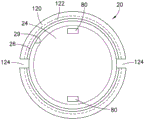
Fig. 4D illustrates a cross-sectional bottom view of a housing according to another exemplary embodiment of the present disclosure.
Fig. 5 and 6 illustrate an illustration of the securing and removal of a cap on a medical implement, such as a needleless connector, according to an exemplary embodiment of the present disclosure.
Fig. 7A is a cross-sectional view of a cap according to yet another exemplary embodiment of the present disclosure.
Fig. 7B is a cross-sectional view of a cap according to yet another exemplary embodiment of the present disclosure.
Throughout the drawings, like reference numerals will be understood to refer to like parts, components and structures.
Detailed Description
The matters illustrated in the description are provided to assist in a comprehensive understanding of exemplary embodiments with reference to the accompanying drawings. Accordingly, those of ordinary skill in the art will recognize that various changes and modifications of the exemplary embodiments described herein can be made within the scope of the appended claims without departing from their full scope and equivalents. Moreover, descriptions of well-known functions and constructions are omitted for clarity and conciseness. Also, certain naming conventions, labels and terms used in the context of the present disclosure are non-limiting and provided for illustrative purposes only to facilitate understanding of exemplary implementations of exemplary embodiments.
Referring to fig. 3A to 6, according to an exemplary embodiment of the present disclosure, the safety locking connector hat 10 includes: an outer housing 20 including a top wall 22 and side walls 26; an inner housing 30 comprising a top wall 32 and a side wall 36 with an opening 37 into an interior cavity 38 and one or more threads 31 on an inner side wall surface 33 of the side wall 36; a peel-off sealing film 40 for sealing the opening; a disinfecting member 50 such as an IPA soaked sponge; and a sealing surface 60, which may be constituted by a surface of a rim of the open bottom of the inner case 30.
After removal of peel seal membrane 40 or upon piercing of the peel seal membrane, cavity 38 of inner housing 30 receives the tip of needleless connector 9 and threadably secures the tip within cavity 38, one or more threads 31 being sufficient to interlock with mating features of the seat or tip of needleless connector 9, as described, for example, in related U.S. patent applications nos. 15/408,278 and 15/408,187 (both of which were filed on 2017, 1, 17).
Referring to, for example, fig. 3A and 3B, in an exemplary implementation of an embodiment of the present disclosure, inner housing 30 is disposed within outer housing 20 such that side wall 26 substantially surrounds side wall 36 and top wall 22 substantially covers top wall 32. The secure interface 100 includes: a first portion 70 that may be disposed on the outer surface 34 of the top wall 32 of the inner housing 30 as a ratcheting feature that includes one or more protrusions 72, such as a tooth or teeth, having a first angled surface 74 and a first vertical surface 76; and a second portion 80 that may be disposed on the inner surface 24 of the top wall 22 of the outer housing 20 as a ratcheting feature that includes one or more protrusions 82, such as a tooth or teeth, having a second angled surface 84 and a second vertical surface 86. The first vertical surface 76 may be substantially perpendicular to the outer surface 34 and the first inclined surface 74 may be at an acute angle to the outer surface 34. In another aspect, the second vertical surface 86 may be substantially perpendicular to the inner surface 24 and the second inclined surface 84 may be at an acute angle to the inner surface 24.
The security interface 100 is configured such that the first portion 70 and the second portion 80 do not engage unless the outer surface 34 is sufficiently close to the inner surface 24 such that the protrusions 72 and 82 can make sufficient contact.
According to another exemplary implementation of the embodiment of the present disclosure shown in the example of fig. 3B, the retention interface for securing the outer housing 20 relative to the inner housing 30 may be implemented, for example, as follows. The outer surface 39 of the sidewall 36 of the inner housing 30 may include an inner housing retention feature, such as a protrusion (or skirt or flange) 110, and the inner surface 29 of the sidewall 26 of the outer housing 20 may include an outer housing retention feature, such as a recess 120. Protrusion 110 and recess 120 are configured to engage, for example, at respective first contact surfaces 112 of protrusion 110 and second contact surfaces 122 of recess 120, such that outer housing 20 is secured to inner housing 30 while allowing rotational movement of outer housing 20 relative to inner housing 30, such as shown with respect to the example of fig. 5 and 6.
The retention interface secures the outer housing 20 relative to the inner housing 30 while allowing sufficient axial movement of the outer surface 34 relative to the inner surface 24, on the one hand, such that the projections 72 and 82 do not have to contact each other when the outer housing 20 is rotated relative to the inner housing 30, and on the other hand, such that the projections 72 and 82 contact each other sufficiently to transfer rotational movement of the outer housing 20 to the inner housing 30.
According to yet further exemplary embodiments of the present disclosure as shown in detail in the example of fig. 3C, the holding interface for fixing the outer housing 20 relative to the inner housing 30 may optionally be implemented, for example, as follows, in addition to or instead of the holding interface as shown in fig. 3B. The outer surface 34 of the top wall 32 of the inner housing 30 may include inner housing retention features, such as latch tabs 130, and the inner surface 24 of the top wall 22 of the outer housing 20 may include outer housing retention features, such as corresponding latch tabs 120. The tabs 130 and 120 are configured to engage, such as by latching the extended skirt 122 of the tabs 120 with the rim 132 of the retention tab 130, such that the outer housing 20 is secured to the inner housing 30 while allowing rotational movement of the outer housing 20 relative to the inner housing 30, as described below with reference to the example of fig. 5 and 6.
For example, referring to fig. 4A-4C, according to an exemplary embodiment of the present disclosure, the outer housing of the safety locking connector cap 10 is further designed to prevent the risk of blockage by providing a hole or opening so that air may pass through the cap if the cap becomes stuck in the air passage (e.g., a person's throat).
As shown in the example of fig. 4A and 4B, any exemplary implementation of the embodiments of the present disclosure may optionally provide one or more openings 92, 94, and/or 96 in the top wall 22 of the outer housing 20 that allow air 200 to pass through the outer housing 20, e.g., between an inner surface of the outer housing 20 and an outer surface of the inner housing 30, as illustrated in the example of fig. 4B. The number, size, and/or shape of the openings 92, 94, and/or 96 may be varied to ensure adequate air passage, for example, to meet safety concerns and to avoid interference with the operation and/or function of the safety interface 100.
Although the examples of fig. 3A and 4A illustrate continuous 360 degree features in which both the protrusion 110 and the recess 120 are optionally formed as respective inner and outer housings 30, 20, according to example embodiments of the present disclosure, at least one or both of the protrusion 110 and the recess 120 may optionally be formed as a local feature. For example, as shown by the cross-sectional bottom view of inner housing 30 in fig. 4C, instead of a continuous 360 degree feature, protrusion 110 may include a plurality of protruding 10 degree portions 114 centered at 90 degree intervals on outer surface 39 of sidewall 36. On the other hand, for example, instead of a continuous 360 degree feature, the recess 120 may have one or more voids 124, as shown by the cross-sectional bottom view of the outer housing 20 in fig. 4D, which may also facilitate further prevention of the risk of clogging by providing an air passage in the event that the cap becomes stuck in the air passage. When forming at least one or both of the protrusion 110 and the recess 120 as a localized feature, the size and/or shape of the portion 114 and/or the void 124 may be appropriately and/or desirably altered while ensuring that the outer housing 20 is properly configured relative to the inner housing 30 to ensure proper operation and/or function of the security interface 100.
Referring to fig. 5 and 6, in accordance with an exemplary implementation of an embodiment of the present disclosure, securing cap 10 to needleless connector 9 is shown in fig. 5, which illustrates applying an axial force 171 that causes axial movement of top wall 22 of outer housing 20 toward top wall 32 of inner housing 30, and applying a rotational force 170 that causes rotational movement of outer housing 20 (e.g., rotational movement in a clockwise direction as may be required to threadably secure cap 10 to needleless connector 9). Axial movement of the top wall 22 toward the top wall 32 reduces the distance between the first portion 70 and the second portion 80 of the safety interface 100, thereby allowing the first portion 70 and the second portion 80 to engage upon application of the rotational force 170. On the other hand, removal of cap 10 from needleless connector 9 is shown in fig. 6, which illustrates application of axial force 173 causing axial movement of top wall 22 of outer housing 20 toward top wall 32 of inner housing 30, and application of rotational force 172 causing rotational movement of outer housing 20 (e.g., rotational movement in a counterclockwise direction as may be required to remove threadingly secured cap 10 from needleless connector 9).
As shown in the example of fig. 5, according to an exemplary implementation of an embodiment of the present disclosure, application of the axial force 171 and the rotational force 170 causes the one or more first protrusions 72 having the first vertical surface 76 and the corresponding one or more second protrusions 82 having the second vertical surface 86 to engage when the oppositely facing substantially vertical surfaces 76 and 86 are in contact, resulting in the rotation of the outer housing 20 being transferred to the inner housing 30 such that the inner housing 30 is rotated in the same rotational direction as the outer housing 20 to rotate the inner housing threads onto the needleless connector 9 to interlock the cap threads 31 with any mating features of the seat or tip of the needleless connector 9 to secure the cap 10 to the needleless connector 9.
As shown in the example of fig. 6, according to an exemplary implementation of an embodiment of the present disclosure, continued application of the rotational force 172 and the axial force 173 causes the one or more first protrusions 72 having the first surface 74 and the corresponding one or more second protrusions 82 having the second surface 84 to engage when the oppositely facing surfaces 74 and 84 are in contact, causing rotation of the outer housing 20 to be transferred to the inner housing 30 such that the inner housing 30 is rotated in the same rotational direction as the outer housing 20 so that the threaded rotation disengages the needleless connector 9 to release the cap threads 31 from any mating features of the tip or seat of the needleless connector 9, thereby removing the cap 10 from the needleless connector 9.
According to an exemplary embodiment, axial force 171 need not be applied as an external force (or as a force of lesser magnitude) because the free axial movement of outer housing 20 relative to inner housing 30 may cause outer housing 20 to move toward inner housing 30 solely due to gravity based on the position of cap 10 relative to needleless connector 9. On the other hand, the force 173 may need to be applied as a large magnitude of external force to ensure that one or more of the first protrusions 72 engage one or more corresponding second protrusions 82 through, for example, an interference fit of the respective surfaces 74 and 84. For example, the slope and shape of the respective surfaces 74 and 84 may be varied to adjust the axial force 173 required to create a sufficient interference fit of the respective surfaces 74 and 84 so that the projections 72 and 82 do not slide relative to each other, but rather engage to transfer rotation of the outer housing 20 to the inner housing 30. For example, enhanced safety may optionally be achieved by increasing the amount of axial force required to engage first portion 70 and second portion 80 to threadably disengage inner housing 30 from needleless connector 9 to remove cap 10 from needleless connector 9.
According to exemplary embodiments of the present disclosure, the outer housing 30 having the safety features described above with reference to fig. 3-6 may optionally be implemented with any and all connector caps (including disinfection caps) having the various features and designs described in applicant's co-pending U.S. patent applications nos. 15/408,278 and 15/408,187 (both of which were filed on 2017, 1, 17), for example by modifying the outer surface of the outer housing of the connector caps disclosed herein, as shown in the illustrative examples of fig. 7A and 7B.
Referring to fig. 7A and 7B, cross-thread disinfecting cap 300 has a housing 302 that includes: a closed top 322; a substantially cylindrical sidewall 304 having an outer sidewall surface 320; and an open bottom 324 having an opening 326 to an interior cavity 328 within the outer housing 302 for receiving the end of the needleless connector. The bottom 324 formed by the sidewall 304 of the housing 302 is non-planar such that a space 370 exists between the planar surface 310 and the bottom 324 of the cap 300. The cavity 328 may receive an alcohol soaked disinfectant sponge 380 and have threads 340 on the inside wall surface of the sidewall 304. The diameter (major diameter 345 and/or minor diameter 346) of threads 340 of cap 300 may not correspond to the threads of a needleless connector. According to an exemplary embodiment of the present disclosure, the outer sidewall surface 320 of the housing 302 may be modified to include the protrusion 110 as a continuous 360 degree feature or as one or more protrusions 114, and the outer surface 34 of the top 322 may be modified to include one or more second protrusions 72. Outer housing 20 may be shaped and configured relative to sidewalls 320 and top 322, which are structures of inner housing 30, to form security interface 100 as shown in the examples of fig. 3-6.
While the present disclosure has been shown and described with reference to certain exemplary embodiments thereof, it will be understood by those skilled in the art that various changes in form and details may be made therein without departing from the spirit and scope of embodiments of the present disclosure. For example, the disinfecting sponge may include any suitable disinfecting substance or other application-specific substance, and may be made of any suitable material. Also, the inner and/or outer shells of the cap may be formed in one piece, or by other suitable processes. Furthermore, as those skilled in the art will readily appreciate, any features or elements of any of the exemplary embodiments of the present disclosure, as described above and illustrated in the drawings, may be implemented individually or in any combination without departing from the spirit and scope of the embodiments of the present disclosure.
Additionally, the included drawings further describe non-limiting examples of implementations of certain exemplary embodiments of the present disclosure and facilitate the description of technologies associated therewith. Any specific or relative dimensions or measurements provided in the other figures, as described above, are exemplary and are not intended to limit the scope or content of the present designs or methods, as will be understood by those skilled in the relevant art(s) of the present disclosure.
Other objects, advantages and salient features of the disclosure will become apparent to those skilled in the art from the details provided, which, taken in conjunction with the annexed drawings, discloses exemplary embodiments of the disclosure.