CN108685177B - electronic cigarette - Google Patents
electronic cigarette Download PDFInfo
- Publication number
- CN108685177B CN108685177B CN201710231988.6A CN201710231988A CN108685177B CN 108685177 B CN108685177 B CN 108685177B CN 201710231988 A CN201710231988 A CN 201710231988A CN 108685177 B CN108685177 B CN 108685177B
- Authority
- CN
- China
- Prior art keywords
- valve
- channel
- electronic cigarette
- liquid storage
- liquid
- Prior art date
- Legal status (The legal status is an assumption and is not a legal conclusion. Google has not performed a legal analysis and makes no representation as to the accuracy of the status listed.)
- Expired - Fee Related
Links
- 239000003571 electronic cigarette Substances 0.000 title claims abstract description 67
- 239000007788 liquid Substances 0.000 claims abstract description 128
- 239000012530 fluid Substances 0.000 claims abstract description 78
- 235000019504 cigarettes Nutrition 0.000 claims abstract description 40
- 239000000779 smoke Substances 0.000 claims abstract description 19
- 238000010438 heat treatment Methods 0.000 claims description 9
- 229920000742 Cotton Polymers 0.000 claims description 6
- 230000000694 effects Effects 0.000 claims description 6
- 238000007789 sealing Methods 0.000 claims description 5
- 239000011796 hollow space material Substances 0.000 claims description 4
- 238000010586 diagram Methods 0.000 description 11
- 230000035515 penetration Effects 0.000 description 8
- 238000000889 atomisation Methods 0.000 description 6
- 238000005516 engineering process Methods 0.000 description 5
- 239000004642 Polyimide Substances 0.000 description 4
- 238000000034 method Methods 0.000 description 4
- 230000000149 penetrating effect Effects 0.000 description 4
- 229920001721 polyimide Polymers 0.000 description 4
- 241000208125 Nicotiana Species 0.000 description 3
- 235000002637 Nicotiana tabacum Nutrition 0.000 description 3
- 230000009471 action Effects 0.000 description 3
- 230000005540 biological transmission Effects 0.000 description 3
- 239000002184 metal Substances 0.000 description 3
- 229910052451 lead zirconate titanate Inorganic materials 0.000 description 2
- 239000007769 metal material Substances 0.000 description 2
- 229920002120 photoresistant polymer Polymers 0.000 description 2
- 238000001020 plasma etching Methods 0.000 description 2
- 230000008569 process Effects 0.000 description 2
- 229910001220 stainless steel Inorganic materials 0.000 description 2
- 239000010935 stainless steel Substances 0.000 description 2
- 238000001816 cooling Methods 0.000 description 1
- 230000007423 decrease Effects 0.000 description 1
- 230000007812 deficiency Effects 0.000 description 1
- 238000006073 displacement reaction Methods 0.000 description 1
- 230000005684 electric field Effects 0.000 description 1
- 230000005484 gravity Effects 0.000 description 1
- HFGPZNIAWCZYJU-UHFFFAOYSA-N lead zirconate titanate Chemical compound [O-2].[O-2].[O-2].[O-2].[O-2].[Ti+4].[Zr+4].[Pb+2] HFGPZNIAWCZYJU-UHFFFAOYSA-N 0.000 description 1
- 238000004519 manufacturing process Methods 0.000 description 1
- 238000012986 modification Methods 0.000 description 1
- 230000004048 modification Effects 0.000 description 1
- 239000002861 polymer material Substances 0.000 description 1
- 239000000843 powder Substances 0.000 description 1
- 238000000926 separation method Methods 0.000 description 1
- 230000032258 transport Effects 0.000 description 1
Images


Classifications
-
- A24F47/008—
Landscapes
- Reciprocating Pumps (AREA)
- Nozzles (AREA)
Abstract
一种电子香烟,包含电源装置;传感器;雾化部件;液体存储部件,具有气体流过的通道及储液容器,通道供雾化部件设置其中,而储液容器内部储置香烟液体;流体输送装置,具有输入通道及输出通道,输入通道连通储液容器,而输出通道连通于雾化部件,以控制香烟液体定量输送至雾化部件产生雾化烟;壳体,内部安装电源装置、传感器、流体输送装置、雾化部件及液体存储部件,外表具有进气口,供外部空气可连通经传感器在连通液体存储部件的通道形成一气流回路。
An electronic cigarette comprises a power supply device; a sensor; an atomizing component; a liquid storage component having a channel for gas flow and a liquid storage container, wherein the channel is provided with the atomizing component, and cigarette liquid is stored in the liquid storage container; a fluid delivery device having an input channel and an output channel, wherein the input channel is connected to the liquid storage container, and the output channel is connected to the atomizing component, so as to control the quantitative delivery of cigarette liquid to the atomizing component to generate atomized smoke; a shell, in which the power supply device, the sensor, the fluid delivery device, the atomizing component and the liquid storage component are installed, and the outer surface has an air inlet, so that external air can be connected to the channel connected to the liquid storage component through the sensor to form an air flow circuit.
Description
【技术领域】【Technical field】
本案关于一种电子香烟,尤指一种具微泵结构的电子香烟。This case is about an electronic cigarette, especially an electronic cigarette with a micro-pump structure.
【背景技术】【Background technique】
电子烟或所谓的电子香烟的使用正迅速扩展中,以作为替代传统抽真实烟草的香烟。如第1A、1B图中所示,电子香烟包括可组装在一起然后安装于第一壳体1a及第二壳体1b内的元件。第一壳体1a及第二壳体1b可为一薄壁金属管,例如不锈钢,具有类似于传统烟草香烟的长度与直径,电子香烟的元件包括电源装置2、传感器3、雾化部件4和液体存储部件5。电源装置2及传感器3安装于第一壳体1a内,以及第一壳体1a上设置至少一进气口1c靠近传感器3的区域。而雾化部件4和液体存储部件5安装于第二壳体1b内,雾化部件4由一支架7做固定支撑,雾化部件4包括电加热器41和套装在电加热器41上的液体渗透部件42以及一紧密地与液体渗透组件42配合的液体传导部件43,电加热器41为中空结构;而液体储存部件5安装于第二壳体1b内,在内部具有气体流过的通道51,以及在通道51外围具有储液容器52,而液体传导部件43套在液体渗透部件42上,液体传导部件43的导通部分431与储液容器52接触,因此,储液容器52上的香烟液体被吸收并渗透到液体渗透部件42。又雾化部件4与传感器3之间设有一进气及电连接部件10形成一气流回路,供与液体储存部件5的通道51连通,使外部空气可由至少一进气口1c进入经过传感器3再经过电加热器41而导入液体储存部件5的通道51内。另外,电子香烟的元件更设有一电极环8,分别与电加热器41的两个引线电连接,电极环8通过进气及电连接部件10和传感器3的连接与电源装置2电连接,传感器3根据气流打开或关闭整个电路,最后一吸嘴9组装于第二壳体1b一端,与液体储存部件5的通道51连通。当用户吸入时,电子香烟内的气体流动。此时,传感器3接通电路,启动电加热器41进行加热。当用户停止吸气时,气体停止流动,并且传感器3关闭电路,以使电加热器41停止加热。如此,将香烟液体由储液容器52经过液体传导部件43的导通部分431渗透到液体渗透部件42,当用户由吸嘴9吸入空气时,电子香烟内的气体流动,传感器3根据气流打开整个电路,电源装置2供应电源至电极环8启动电加热器41进行加热,而香烟液体渗透到液体渗透部件42便经电加热器41而产生雾化,用户即可由吸嘴9吸入液体储存部件5的通道51的雾化烟。The use of electronic cigarettes, or so-called electronic cigarettes, is rapidly expanding as an alternative to traditional cigarettes that smoke real tobacco. As shown in Figures 1A and 1B, the electronic cigarette includes components that can be assembled together and then mounted within a
上述电子香烟的香烟液体由液体传导部件43的导通部分431渗透到液体渗透部件42的设计,会有下列几点问题:The cigarette liquid of the above-mentioned electronic cigarette is penetrated by the conducting
1.因液体传导部件43的导通部分431无法精准控制渗透量,而产生液体渗透部件42吸附香烟液体不均的现象,导致液体渗透部件42含香烟液体量少的部分,产生液滴不均匀,经电加热器41加热产生焦味烟雾,吸烟者会感到口感不适。1. Because the conducting
2.因液体传导部件43的导通部分431无法精准控制渗透量,尤其是当吸嘴9朝上时,重力往下造成液体储存部件5的通道51外围的储液容器52内香烟液体无法完全止住渗透液体渗透部件42的量,导致渗透液体渗透部件42含量饱满时,会滴落香烟液体至支架7及进气及电连接部件10而经过传感器3再由至少一进气口1c漏出,造成渗油问题。2. Because the conducting
另外,目前现有雾化电子香烟仍存在许多问题和缺点,例如雾化不良,最终雾化烟雾中液滴大,不同尺寸液滴产生的不均匀烟雾,烟雾中水分过多,口感差,在一些条件下,烟由于冷却不足而处于高温,并且将引起不适。上述问题导致真实香烟和吸烟者的电子香烟之间存在显著差异,这不利于吸烟者选择电子香烟代替真实香烟。In addition, the existing atomized electronic cigarettes still have many problems and shortcomings, such as poor atomization, large droplets in the final atomized smoke, uneven smoke generated by droplets of different sizes, excessive moisture in the smoke, and poor taste. Under some conditions, the smoke is at a high temperature due to insufficient cooling and will cause discomfort. The above problems lead to a significant difference between real cigarettes and smokers' electronic cigarettes, which is not conducive for smokers to choose electronic cigarettes instead of real cigarettes.
有鉴于此,如何发展一种可改善上述已知电子香烟技术缺失,发展一种代替真实香烟的电子香烟,实为目前迫切需要解决的问题。In view of this, how to develop an electronic cigarette that can improve the above-mentioned deficiencies in the known electronic cigarette technology and develop an electronic cigarette that replaces the real cigarette is a problem that needs to be solved urgently at present.
【发明内容】[Content of the invention]
本案的主要目的在于提供一种电子香烟,主要由流体控制装置结合雾化部件的设置,形成一可控制开关精准控制香烟液体渗透雾化部件的液体渗透部件的量,俾解决已知电子香烟技术的液滴产生不均匀烟雾口感差及渗油问题。The main purpose of this case is to provide an electronic cigarette, which is mainly composed of a fluid control device combined with the setting of the atomizing part to form a controllable switch to precisely control the amount of the liquid penetrating part of the cigarette liquid permeating the atomizing part, so as to solve the problem of the known electronic cigarette technology The droplets produce uneven smoke, poor taste and oil seepage problems.
为达上述目的,本案的较广义实施态样为提供一种电子香烟,一电源装置,提供驱动电源及控制信号;一传感器,根据通过气流,以打开或关闭该电源装置的整个电路;一雾化部件,包括电加热器和组装在电加热器上的液体渗透部件;一液体存储部件,具有一气体流过的通道及一储液容器,该通道供该雾化部件的电加热器设置其中,而该储液容器内部储置香烟液体;一流体输送装置,具有一输入通道及一输出通道,该输入通道连通该储液容器,而输出通道连通于该液体渗透部件,供该储液容器的香烟液体输送渗透至液体渗透部件中,而控制香烟液体滴落量至该雾化部件的电加热器上产生烟雾;一壳体,内部安装该电源装置、该传感器、该流体输送装置、该雾化部件及该液体存储部件,外表具有一进气口,供外部空气可连通经该传感器在连通该液体存储部件的通道形成一气流回路,以及内部安装一进气及电连接部件,供该流体输送装置、该雾化部件的电加热器透过该进气及电连接部件能与该电源装置及该传感器电性连接而获得电源与控制信号;以及一吸嘴,封闭该壳体一端,并连通该液体存储部件的通道,并具有一开孔,供吸引该液体存储部件的通道的烟雾气流。In order to achieve the above purpose, the broader implementation aspect of this case is to provide an electronic cigarette, a power supply device, which provides driving power and control signals; a sensor, according to the passing air flow, to open or close the entire circuit of the power supply device; The atomizing part includes an electric heater and a liquid permeating part assembled on the electric heater; a liquid storage part has a channel through which gas flows and a liquid storage container, the channel is provided for the electric heater of the atomizing part to be arranged therein , and the cigarette liquid is stored inside the liquid storage container; a fluid delivery device has an input channel and an output channel, the input channel is connected to the liquid storage container, and the output channel is connected to the liquid permeable part for the liquid storage container. The cigarette liquid is transported and penetrated into the liquid permeation part, and the amount of cigarette liquid dripping is controlled to generate smoke on the electric heater of the atomizing part; a casing, the power supply device, the sensor, the fluid conveying device, the The atomizing part and the liquid storage part have an air inlet on the outside for external air to communicate through the sensor to form an air flow circuit in the channel communicating with the liquid storage part, and an air intake and electrical connection part are installed inside for the The fluid delivery device and the electric heater of the atomizing part can be electrically connected with the power supply device and the sensor through the air intake and the electrical connection part to obtain power supply and control signals; and a suction nozzle, which closes one end of the casing, and communicate with the channel of the liquid storage part, and has an opening for attracting the smoke flow of the channel of the liquid storage part.
【附图说明】【Description of drawings】
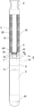
图1A所示为已知电子香烟的剖面示意图。FIG. 1A is a schematic cross-sectional view of a known electronic cigarette.
图1B所示为已知电子香烟的雾化部件部位放大示意图。FIG. 1B is an enlarged schematic view of the atomizing part of a known electronic cigarette.
图2A所示为本案电子香烟的剖面示意图。FIG. 2A shows a schematic cross-sectional view of the electronic cigarette of the present invention.
图2B所示为本案电子香烟的电源装置部位放大示意图。FIG. 2B is an enlarged schematic diagram of the power supply device of the electronic cigarette of the present invention.
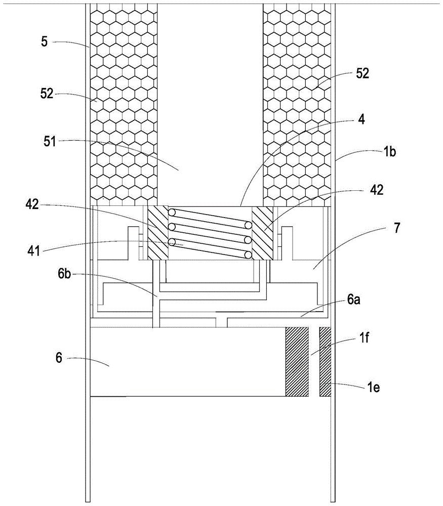
图2C所示为本案电子香烟的雾化部件部位放大示意图。FIG. 2C shows an enlarged schematic diagram of the atomizing part of the electronic cigarette of the present invention.
图3所示为本案电子香烟的电源装置相关构件的方块图。FIG. 3 is a block diagram showing the relevant components of the power supply device of the electronic cigarette of the present invention.
图4所示为本案电子香烟的流体输送装置的立体外观示意图。FIG. 4 is a schematic three-dimensional appearance diagram of the fluid delivery device of the electronic cigarette of the present invention.
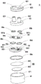
图5A所示为本案电子香烟的流体输送装置的正面分解结构示意图。FIG. 5A shows a schematic diagram of the front exploded structure of the fluid delivery device of the electronic cigarette of the present invention.
图5B所示为本案电子香烟的流体输送装置的背面分解结构示意图。FIG. 5B shows a schematic diagram of the back exploded structure of the fluid delivery device of the electronic cigarette of the present invention.
图6A所示为本案电子香烟的流体输送装置的阀本体正面视得示意图。FIG. 6A is a schematic view of the front view of the valve body of the fluid delivery device of the electronic cigarette of the present invention.
图6B所示为本案电子香烟的流体输送装置的阀本体底面视得示意图。FIG. 6B is a schematic view of the bottom surface of the valve body of the fluid delivery device of the electronic cigarette of the present invention.
图7A所示为本案电子香烟的流体输送装置的阀腔体座正面视得示意图。FIG. 7A is a schematic front view of the valve cavity seat of the fluid delivery device of the electronic cigarette of the present invention.
图7B所示为本案电子香烟的流体输送装置的阀腔体座底面视得示意图。FIG. 7B is a schematic view of the bottom surface of the valve cavity seat of the fluid delivery device of the electronic cigarette of the present invention.
图8所示为本案电子香烟的流体输送装置的阀膜片正面视得示意图。FIG. 8 is a schematic view of the front view of the valve diaphragm of the fluid delivery device of the electronic cigarette of the present invention.
图9所示为本案电子香烟的流体输送装置的阀腔体座立体示意图。FIG. 9 is a three-dimensional schematic diagram of the valve cavity seat of the fluid delivery device of the electronic cigarette of the present invention.
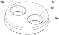
图10A所示为本案电子香烟的流体输送装置的阀门盖体正面视得示意图。FIG. 10A is a schematic diagram of the front view of the valve cover of the fluid delivery device of the electronic cigarette of the present invention.
图10B所示为本案电子香烟的流体输送装置的阀门盖体底面视得示意图。FIG. 10B is a schematic view of the bottom surface of the valve cover of the fluid delivery device of the electronic cigarette of the present invention.
图11所示为本案电子香烟的流体输送装置的剖面示意图。FIG. 11 is a schematic cross-sectional view of the fluid delivery device of the electronic cigarette of the present invention.
图12A所示为本案电子香烟的流体输送装置的输送流体作动状态示意图1。FIG. 12A shows a schematic diagram 1 of the fluid delivery action state of the fluid delivery device of the electronic cigarette of the present invention.
图12B所示为本案电子香烟的流体输送装置的输送流体作动状态示意图2。FIG. 12B shows a schematic diagram 2 of the fluid delivery action state of the fluid delivery device of the electronic cigarette of the present invention.
【具体实施方式】【Detailed ways】
体现本案特征与优点的一些典型实施例将在后段的说明中详细叙述。应理解的是本案能够在不同的态样上具有各种的变化,其皆不脱离本案的范围,且其中的说明及图示在本质上当作说明之用,而非用以限制本案。Some typical embodiments embodying the features and advantages of the present case will be described in detail in the description of the latter paragraph. It should be understood that this case can have various changes in different aspects, all of which do not depart from the scope of this case, and the descriptions and diagrams therein are essentially used for illustration rather than limiting this case.
请参阅图2A、图2B及图2C所示,本案的电子香烟包括壳体1、电源装置2、传感器3、雾化部件4、液体存储部件5、流体输送装置6及吸嘴9。其中壳体1可由一第一壳体1a及一第二壳体1b可相互对接组装而成,形成可更换第二壳体1b新替品的电子香烟的元件,而第一壳体1a及第二壳体1b可为一薄壁金属管,例如不锈钢,具有类似于传统烟草香烟的长度与直径。电源装置2及传感器3安装于第一壳体1a内,以及第一壳体1a上设置至少一进气口1c于靠近传感器3的区域。2A , 2B and 2C , the electronic cigarette in this case includes a
又如图3所示,电源装置2包括一电源模块21、一控制模块22、一加热器模块23及一发光二极管24,电源模块21是可以是可充电电池或一次性电池的电池控制模块,提供控制模块22、加热器模块23及传感器3的驱动电源,控制模块22提供加热器模块23的控制信号,以及提供该流体输送装置6的驱动电源及控制信号,而加热器模块23提供雾化部件4的雾化加热的电能,而发光二极管24设置于第一壳体1a的前端,受控制模块22的控制提供电子香烟操作讯息警示之用,也可提供吸烟者抽吸雾化烟气流流通强弱的提示作用。3, the
请参阅图2A、图2B及图2C所示,传感器3设置于电源装置2之前端,中间并间隔一气流腔室1d,供使外部空气可由至少一进气口1c进入再经过传感器3形成一气流回路,传感器3可为一空气压力传感器或气流传感器。在一实施例中,使用气流传感器,提供信号给控制模块22,可根据通过气流,以打开或关闭电源装置2整个电性连接,亦即打开或关闭控制模块22的驱动电源及控制信号及加热器模块23的驱动电源;又,第一壳体1a内也组设一进气及电连接部件10位在传感器3前方,供电源装置2的电连接至雾化部件4及流体输送装置6,以及提供传感器3的气流通道连通到第二壳体1b中。Please refer to FIGS. 2A , 2B and 2C. The
如图2A及图2C所示,雾化部件4和液体存储部件5安装于第二壳体1b内,雾化部件4由一支架7做固定支撑,雾化部件4包括电加热器41和套装在电加热器41上的液体渗透部件42,电加热器41为中空结构,电加热器41的两个引线(未图示)透过进气及电连接部件10连接至电源装置2和传感器3实现电连接,并根据传感器3检测到的流动情况控制电加热器41开始加热或停止加热。As shown in FIG. 2A and FIG. 2C, the
如图2A及图2C所示,液体储存部件5安装于第二壳体1b内,在内部具有一气体流过的通道51及一储液容器52,储液容器52内部储置香烟液体,并与流体输送装置6的输入通道6a连通,以流体输送装置6做作为一阀开关输送储液容器52上的香烟液体,而流体输送装置6透过一支撑座1e支撑定位安装于第二壳体1b内,且该支撑座1e具有一气体通道1f,以及流体输送装置6的输出通道6b连通至雾化部件4的液体渗透部件42中,因此,储液容器52上的香烟液体可被流体输送装置6输送渗透至雾化部件4的液体渗透部件42中,实施雾化作用,而液体储存部件5的通道51透过气体通道1f而与进气及电连接部件10连通,使外部空气可由至少一进气口1c进入经过传感器3再经过雾化部件4的电加热器41而导入液体储存部件5的通道51内。As shown in FIG. 2A and FIG. 2C , the
请参阅图4、图5A、图5B、图6A、图6B、图7A及图7B所示,阀本体63及阀腔体座65为本案流体输送装置6中导引流体进出的主要结构。其中阀本体63具有一个入口通道631以及一个出口通道632分别贯穿第一表面633及第二表面634之间,而入口通道631于第二表面634上连通一入口开口6311,且第二表面634具有环绕入口开口6311的凹槽6341,以及具有环绕入口开口6311突起的凸部结构6343,而出口通道632于第二表面634上连通一出口开口6321,且第二表面634具有环绕出口开口6321的凹槽6342,另外在阀本体63的第二表面634上设置数个卡榫槽63b。4, 5A, 5B, 6A, 6B, 7A and 7B, the
阀腔体座65于第三表面655上设置数个卡榫65a,可对应套入阀本体63的卡榫槽63b中,以使阀本体63与阀腔体座65可相互结合堆叠定位。阀腔体座65上具有贯穿第三表面655至第四表面656的入口阀门通道651及出口阀门通道652,以及于第三表面655上具有环绕入口阀门通道651的凹槽653,且第三表面655上具有环绕出口阀门通道652突起的凸部结构6521,以及具有环绕出口阀门通道652的凹槽654,另外,于第四表面656上凹置一压力腔室657,分别与入口阀门通道651及出口阀门通道652连通,且第四表面656于压力腔室657外部具有段差槽658。The
请参阅图5A、图5B及图8所示,阀膜片64主要材质为聚亚酰胺(Polyimide,PI)高分子材料时,其制造方法主要利用反应离子气体干蚀刻(reactive ion etching,RIE)的方法,以感光性光阻涂布于阀门结构的上,并曝光显影出阀门结构图案后,再以进行蚀刻,由于有光阻覆盖处会保护聚亚酰胺(Polyimide,PI)片不被蚀刻,因而可蚀刻出阀膜片64上的阀门结构。阀膜片64为一平坦薄片结构。如图8所示,阀膜片64在两个贯穿区域64a、64b中各保留有厚度相同的两阀门片641a、641b,且环绕阀门片641a、641b周边各设置多个延伸支架642a、642b作以弹性支撑,并使每个延伸支架642a、642b相邻之间各形成一镂空孔643a、643b,如此厚度相同的一阀门片641a、641b可受作用力在阀膜片64上借由延伸支架642a、642b弹性支撑而凸伸变形一位移量形成阀门开关结构。阀门片641a、641b可为圆型、长方型、正方形或各种几何图型,但不以此为限。又,阀膜片64上设有多个定位孔64c,可套入阀腔体座65于第三表面655的卡榫65a中,以定位阀膜片64承载于阀腔体座65上,供阀门片641a、641b分别封盖阀腔体座65的入口阀门通道651及出口阀门通道652(如图8所示),于本实施例中,卡榫65a数量为2,因此定位孔64c数量为2个,但不以此为限,可依卡榫65a数量而设置。Please refer to FIG. 5A , FIG. 5B and FIG. 8 , when the
请参阅图11所示,阀本体63与阀腔体座65相互结合堆叠时,阀本体63的凹槽6341、6342分别供一密封环68a、68b套入其上,而阀腔体座65的凹槽653、654分别供一密封环68c、68d套入其上,阀本体63与阀腔体座65之间相互结合堆叠,可利用密封环68a、68b、68c、68d的设置,以对周边防止流体渗漏,如此阀本体63的入口通道631对应阀腔体座65的入口阀门通道651,并以阀膜片64的阀门片641a的启闭入口通道631与入口阀门通道651之间连通,以及阀本体63的出口通道632对应阀腔体座65的出口阀门通道652,并以阀膜片64的阀门片641b的启闭出口通道632与出口阀门通道652之间连通,而当阀膜片64的阀门片641a的开启时,入口通道631导入流体即可经过入口阀门通道651而注入汇流于压力腔室657中,而当阀膜片64的阀门片641b的开启时,注入压力腔室657流体即可经过出口阀门通道652而由出口通道632排出于外。Referring to FIG. 11 , when the
请再参阅图5A及图5B所示,致动器66由振动板661以及压电元件662组装而成,其中压电元件662贴附固定于振动板661的表面。于本实施例中,振动板661为金属材质,压电元件662可采用高压电数的锆钛酸铅(PZT)系列的压电粉末制造而成,以贴附固定于振动板661上,以供施加电压驱动压电元件662产生形变,致使振动板661亦随的产生做垂直向往复振动形变,用以驱动流体输送装置6的作动。而致动器66的振动板661为组设于阀腔体座65的第四表面656上以封盖压力腔室657,且第四表面656于压力腔室657外部的段差槽658,供一密封环68e套置其中,以对压力腔室657周边防止流体渗漏。Please refer to FIG. 5A and FIG. 5B again, the
由上述说明可知,阀本体63、阀膜片64、阀腔体座65、致动器66可构成流体输送装置6的输送流体导引进出的主要结构。但如此堆叠结合的结构要如何定位,而且无须以锁付元件(例如:螺丝、螺帽、螺栓等)去锁付定位组装,是本发明所要实施的主要课题。因此以下就采用阀门盖体62及外筒67的设计,将阀本体63、阀膜片64、阀腔体座65、致动器66依序层叠于外筒67之内部,再以阀门盖体62直接紧配合于外筒67之内部定位组装而成进行说明。As can be seen from the above description, the
请参阅图5A、图5B及图9所示,外筒67为金属材质,具有内壁671围绕一中空空间,且外筒67之内壁671底部具有凸环结构672。再请参阅图10A及图10B所示,阀门盖体62也为一金属材质,具有第一贯穿孔621及第二贯穿孔622,分别可供与阀本体63的入口通道631及出口通道632相对应套置入,以及阀门盖体62的底缘具有一倒角623,且阀门盖体62之外径尺寸为略大于外筒67之内壁671尺寸。Please refer to FIGS. 5A , 5B and 9 , the
因此参阅第5A、图5B所示,阀本体63、阀膜片64、阀腔体座65、致动器66依序层叠后置入于外筒67之内壁671中,让整个层叠结构承载于外筒67的凸环结构672上,促使阀门盖体62以外径尺寸略大于外筒67之内壁671尺寸的设计,利用倒角623可顺利导入外筒67之内壁671中,而相互紧配合组接结合定位阀本体63、阀膜片64、阀腔体座65、致动器66依序层叠形成流体输送装置6,而致动器66也可于外筒67之内壁671中空空间中,压电元件662受施加电压而驱动振动板661做垂直往复运动而形变共振,达成无须以锁付元件(例如:螺丝、螺帽、螺栓等)去锁付定位组装的流体输送装置6。Therefore, referring to FIGS. 5A and 5B , the
如图11所示,本案所构成流体输送装置6,阀腔体座65的入口阀门通道651与阀本体63的入口开口6311相对应设置,其间并以阀膜片64的阀门片641a来封闭做阀门结构的作用,且阀门片641a封盖阀本体63的入口开口6311,同时贴合阀本体63的凸部结构6343而产生一预力(Preforce)作用,有助于产生更大的预盖紧效果,以防止逆流,而出口阀门通道652与阀本体63的出口开口6321相对应设置,其间并以阀膜片64的阀门片641b来封闭做阀门结构的作用,且阀膜片64的阀门片641b封盖阀腔体座65的出口阀门通道652,同时贴合阀腔体座65的凸部结构6521而产生一预力(Preforce)作用,有助于产生更大的预盖紧效果,以防止逆流压力腔室657,故本案所构成流体输送装置6在不作动的情况下,阀本体63的入口通道631以及出口通道632之间不会产逆流作用。As shown in FIG. 11 , in the
由上述说明可知,本案流体输送装置6在具体实施流体传输的操作,如图12A所示,当致动器66的压电元件662受施加电压而致动使振动板661下凹变形,此时压力腔室657的体积会增加,因而产生吸力,使阀膜片64的阀门片641a承受一吸力迅速开启,使流体可大量地自阀本体63上的入口通道631被吸取进来,并流经阀本体63的入口开口6311、阀膜片64的镂空孔643a、阀腔体座65的入口阀门通道651流至压力腔室657内暂存,同时出口阀门通道652内也受到吸力,阀膜片64的阀门片641b受此吸力作用,借由延伸支架642b的支撑而产生整个向下平贴紧靠于凸部结构6521呈现关闭状态。It can be seen from the above description that the
其后,图12B所示,当施加于压电元件662的电场方向改变后,压电元件662将使振动板661上凸变形,此时压力腔室657收缩而体积减小,使压力腔室657内流体受挤压,而同时入口阀门通道651内受到推力,阀膜片64的阀门片641a受此推力作用,借由延伸支架642a的支撑而产生整个向上平贴紧靠于凸部结构6343呈现关闭状态,流体无法由入口阀门通道651逆流,而此时出口阀门通道652内也受到推力,阀膜片64的阀门片641b受此推力作用,借由延伸支架42b的支撑而产生整个向上脱离平贴紧靠于凸部结构6521的状态,呈现开启状态,流体即可由出口阀门通道652流出压力腔室657之外,经由阀腔体座65的出口阀门通道652、阀膜片64上的镂空孔643b、阀本体63上的出口开口6321及出口通道632而流出流体输送装置6之外,故完成流体传输的过程,重复图12A及图12B所的操作,即可持续进行流体的输送,如此采用本案流体输送装置6可使流体于传送过程中不会产生回流的情形,达到高效率的传输。Thereafter, as shown in FIG. 12B, when the direction of the electric field applied to the
上述流体输送装置6组装在传感器3和雾化部件4之间,流体输送装置6的入口通道631连通输入通道6a至储液容器52,而流体输送装置6的出口通道632连通输出通道6b,将香烟液体渗透至液体渗透部件42中,因此流体输送装置6由控制模块22提供施加电压控制驱动,以提供香烟液体由储液容器52定量输送出来,并作为一开关,能够控制储液容器52内香烟液体供输,让香烟液体定量输出,提供液体渗透部件42上吸附香烟液体能得到均匀渗透,以产生液滴均匀化,也使体渗透部件42含量饱满时可控制关闭输送,如此流体控制装置6结合雾化部件4的设置,形成一可控制开关精准控制香烟液体渗透雾化部件4的液体渗透部件42的量,俾解决已知电子香烟技术的液滴产生不均匀烟雾口感差及渗油问题。The above-mentioned
再参阅如图2A及图2C所示,吸嘴9组装于第二壳体1b一端,与液体储存部件5的通道51连通,而吸嘴9具有一滤棉91及一开孔92,该滤棉91放置封闭在液体储存部件5的通道51一端,可使初始加热雾化未完全的香烟液体被滤棉91阻隔,形成一防吸入的过滤保护措施。2A and 2C again, the
由上述可知,本案的电子香烟的具体实施说明如下,当用户由吸嘴9的开孔92吸入时,电子香烟内的气体流动,此时,传感器3接通电路,启动电加热器41进行加热;当用户由吸嘴9的开孔92停止吸气时,气体停止流动,并且传感器3关闭电路,以使电加热器41停止加热。如此,本案流体控制装置6结合雾化部件4的设置,形成一可控制开关精准控制香烟液体渗透雾化部件4的液体渗透部件42的量,将香烟液体由储液容器52经过流体控制装置6控制而定量渗透到液体渗透部件42,当用户由吸嘴9的开孔92吸入空气时,电子香烟内的气体流动,传感器3根据气流打开整个电路,电源装置2供应电源至加热器模块23启动电加热器41进行加热,并可控制香烟液体定量渗透到液体渗透部件42,且使该香烟液体定量输送至电加热器41而产生雾化,用户即可由吸嘴9的开孔92吸入液体储存部件5的通道51的雾化烟。It can be seen from the above that the specific implementation of the electronic cigarette in this case is described as follows. When the user inhales through the
综上所述,本案提供一种电子香烟,主要由流体控制装置结合电子香烟的雾化部件的设置,形成一可控制开关精准控制香烟液体渗透雾化部件的液体渗透部件的量,且流体控制装置具逆流的输送作业,以达到高效率的传输,俾解决已知电子香烟技术的液滴产生不均匀烟雾口感差及渗油问题。是以,本案的流体输送装置极具产业的价值,爰依法提出申请。To sum up, this case provides an electronic cigarette, which is mainly composed of a fluid control device combined with the setting of the atomizing part of the electronic cigarette to form a controllable switch to precisely control the amount of the liquid penetrating part of the cigarette liquid permeating the atomizing part, and the fluid control device. The device has a countercurrent conveying operation to achieve high-efficiency transmission, so as to solve the problems of uneven smoke and poor taste and oil leakage caused by the known electronic cigarette technology. Therefore, the fluid conveying device in this case is of great industrial value, and an application should be filed in accordance with the law.
本案得由熟习此技术的人士任施匠思而为诸般修饰,然皆不脱如附申请专利范围所欲保护者。This case can be modified by a person who is familiar with this technology, and all kinds of modifications can be made without departing from the protection of the scope of the patent application attached.
【符号说明】【Symbol Description】
1:壳体1: Shell
10:进气及电连接部件10: Air intake and electrical connection parts
1a:第一壳体1a: first shell
1b:第二壳体1b: Second housing
1c:进气口1c: Air intake
1d:气流腔室1d: Airflow Chamber
1e:支撑座1e: Support seat
1f:气流通道1f: Airflow channel
2:电源装置2: Power supply unit
21:电源模块21: Power Module
22:控制模块22: Control module
23:加热器模块23: Heater Module
24:发光二极管24: LEDs
3:传感器3: Sensor
4:雾化部件4: Atomization parts
41:电加热器41: Electric heater
42:液体渗透部件42: Liquid Permeable Parts
43:液体传导部件43: Liquid conducting parts
431:导通部分431: conduction part
5:液体存储部件5: Liquid storage parts
51:通道51: Channel
52:储液容器52: Reservoir
6:流体输送装置6: Fluid delivery device
6a:输入通道6a: Input channel
6b:输出通道6b: output channel
62:阀门盖体62: valve cover
621:第一贯穿孔621: First through hole
622:第二贯穿孔622: Second through hole
623:倒角623: Chamfer
63:阀本体63: Valve body
631:入口通道631: Entryway
6311:入口开口6311: Entrance opening
632:出口通道632: Exit Channel
6321:出口开口6321: Exit opening
633:第一表面633: First Surface
634:第二表面634: Second Surface
6341、6342:凹槽6341, 6342: Groove
6343:凸部结构6343: Bump Structure
63b:卡榫槽63b: Tenon groove
64:阀膜片64: Valve Diaphragm
64a、64b:贯穿区域64a, 64b: Through area
641a、641b:阀门片641a, 641b: valve plate
642a、642b:延伸支架642a, 642b: Extension brackets
643a、643b:镂空孔643a, 643b: Hollow Holes
64c:定位孔64c: Positioning hole
65:阀腔体座65: valve cavity seat
651:入口阀门通道651: Inlet valve passage
652:出口阀门通道652: Outlet valve passage
6521:凸部结构6521: convex structure
653、654:凹槽653, 654: Groove
655:第三表面655: Third Surface
656:第四表面656: Fourth Surface
657:压力腔室657: Pressure Chamber
658:段差槽658: Level difference slot
65a:卡榫65a: Tenon
66:致动器66: Actuator
661:振动板661: Vibration Plate
662:压电元件662: Piezoelectric element
67:外筒67: Outer cylinder
671:内壁671: Inner Wall
672:凸环结构672: Convex ring structure
68a、68b、68c、68d、68e:密封环68a, 68b, 68c, 68d, 68e: sealing ring
7:支架7: Bracket
8:电极环8: Electrode ring
9:吸嘴9: suction nozzle
91:滤棉91: Filter cotton
92:开孔92: Opening
Claims (15)
Priority Applications (1)
| Application Number | Priority Date | Filing Date | Title |
|---|---|---|---|
| CN201710231988.6A CN108685177B (en) | 2017-04-11 | 2017-04-11 | electronic cigarette |
Applications Claiming Priority (1)
| Application Number | Priority Date | Filing Date | Title |
|---|---|---|---|
| CN201710231988.6A CN108685177B (en) | 2017-04-11 | 2017-04-11 | electronic cigarette |
Publications (2)
| Publication Number | Publication Date |
|---|---|
| CN108685177A CN108685177A (en) | 2018-10-23 |
| CN108685177B true CN108685177B (en) | 2020-06-16 |
Family
ID=63843454
Family Applications (1)
| Application Number | Title | Priority Date | Filing Date |
|---|---|---|---|
| CN201710231988.6A Expired - Fee Related CN108685177B (en) | 2017-04-11 | 2017-04-11 | electronic cigarette |
Country Status (1)
| Country | Link |
|---|---|
| CN (1) | CN108685177B (en) |
Families Citing this family (1)
| Publication number | Priority date | Publication date | Assignee | Title |
|---|---|---|---|---|
| UA129289C2 (en) * | 2018-12-07 | 2025-03-12 | Філіп Морріс Продактс С.А. | AEROSOL GENERATING SYSTEM AND METHOD FOR GENERATING AEROSOL |
Citations (7)
| Publication number | Priority date | Publication date | Assignee | Title |
|---|---|---|---|---|
| CN101581291A (en) * | 2008-05-16 | 2009-11-18 | 研能科技股份有限公司 | Fluid delivery device |
| CN201379072Y (en) * | 2009-02-11 | 2010-01-13 | 韩力 | An improved atomized electronic cigarette |
| CN203709256U (en) * | 2014-01-13 | 2014-07-16 | 潘凡 | Disposable electronic cigarette |
| CN104736005A (en) * | 2012-10-05 | 2015-06-24 | 卓智微电子有限公司 | electronic cigarette device |
| CN105581376A (en) * | 2015-12-29 | 2016-05-18 | 广东亚一半导体应用科技有限公司 | Electronic cigarette and liquid supply device for same |
| WO2016118645A1 (en) * | 2015-01-22 | 2016-07-28 | Fontem Holdings 1 B.V. | Electronic vaporization devices |
| CN106455724A (en) * | 2014-06-09 | 2017-02-22 | 尼科创业控股有限公司 | Electronic vapour provision system |
-
2017
- 2017-04-11 CN CN201710231988.6A patent/CN108685177B/en not_active Expired - Fee Related
Patent Citations (7)
| Publication number | Priority date | Publication date | Assignee | Title |
|---|---|---|---|---|
| CN101581291A (en) * | 2008-05-16 | 2009-11-18 | 研能科技股份有限公司 | Fluid delivery device |
| CN201379072Y (en) * | 2009-02-11 | 2010-01-13 | 韩力 | An improved atomized electronic cigarette |
| CN104736005A (en) * | 2012-10-05 | 2015-06-24 | 卓智微电子有限公司 | electronic cigarette device |
| CN203709256U (en) * | 2014-01-13 | 2014-07-16 | 潘凡 | Disposable electronic cigarette |
| CN106455724A (en) * | 2014-06-09 | 2017-02-22 | 尼科创业控股有限公司 | Electronic vapour provision system |
| WO2016118645A1 (en) * | 2015-01-22 | 2016-07-28 | Fontem Holdings 1 B.V. | Electronic vaporization devices |
| CN105581376A (en) * | 2015-12-29 | 2016-05-18 | 广东亚一半导体应用科技有限公司 | Electronic cigarette and liquid supply device for same |
Also Published As
| Publication number | Publication date |
|---|---|
| CN108685177A (en) | 2018-10-23 |
Similar Documents
| Publication | Publication Date | Title |
|---|---|---|
| TWI642369B (en) | Electronic cigarette | |
| CN206629997U (en) | Electronic cigarette | |
| TWI640257B (en) | Electronic cigarette | |
| TWI625099B (en) | Electronic cigarette | |
| TWI640256B (en) | Electronic cigarette | |
| TWI644626B (en) | Driving module of electronic cigarette | |
| TWI653944B (en) | Electronic cigarette | |
| CN108685183B (en) | electronic cigarette | |
| TWI644625B (en) | Electronic cigarette | |
| TWI640255B (en) | Electronic cigarette | |
| TWI631910B (en) | Electronic cigarette | |
| CN108685179A (en) | Electronic cigarette | |
| CN108968151B (en) | electronic cigarette | |
| CN108685181B (en) | Electronic cigarette | |
| TWI642368B (en) | Electronic cigarette | |
| CN108685178B (en) | Electronic cigarette | |
| CN210130352U (en) | electronic cigarette | |
| CN210130351U (en) | electronic cigarette | |
| CN108685177B (en) | electronic cigarette | |
| CN108685180B (en) | electronic cigarette | |
| TWM544801U (en) | Electronic cigarette | |
| CN210901392U (en) | Electronic cigarette | |
| CN210747234U (en) | Electronic cigarette | |
| CN210747222U (en) | Electronic cigarette | |
| TWM546115U (en) | Electronic cigarette |
Legal Events
| Date | Code | Title | Description |
|---|---|---|---|
| PB01 | Publication | ||
| PB01 | Publication | ||
| SE01 | Entry into force of request for substantive examination | ||
| SE01 | Entry into force of request for substantive examination | ||
| GR01 | Patent grant | ||
| GR01 | Patent grant | ||
| CF01 | Termination of patent right due to non-payment of annual fee | ||
| CF01 | Termination of patent right due to non-payment of annual fee |
Granted publication date: 20200616 |