CN108621943B - System and method for dynamically displaying images on a vehicle electronic display - Google Patents
System and method for dynamically displaying images on a vehicle electronic display Download PDFInfo
- Publication number
- CN108621943B CN108621943B CN201810185721.2A CN201810185721A CN108621943B CN 108621943 B CN108621943 B CN 108621943B CN 201810185721 A CN201810185721 A CN 201810185721A CN 108621943 B CN108621943 B CN 108621943B
- Authority
- CN
- China
- Prior art keywords
- image
- vehicle
- electronic display
- primary
- primary image
- Prior art date
- Legal status (The legal status is an assumption and is not a legal conclusion. Google has not performed a legal analysis and makes no representation as to the accuracy of the status listed.)
- Active
Links
Images


Classifications
-
- B—PERFORMING OPERATIONS; TRANSPORTING
- B60—VEHICLES IN GENERAL
- B60R—VEHICLES, VEHICLE FITTINGS, OR VEHICLE PARTS, NOT OTHERWISE PROVIDED FOR
- B60R16/00—Electric or fluid circuits specially adapted for vehicles and not otherwise provided for; Arrangement of elements of electric or fluid circuits specially adapted for vehicles and not otherwise provided for
- B60R16/02—Electric or fluid circuits specially adapted for vehicles and not otherwise provided for; Arrangement of elements of electric or fluid circuits specially adapted for vehicles and not otherwise provided for electric constitutive elements
- B60R16/023—Electric or fluid circuits specially adapted for vehicles and not otherwise provided for; Arrangement of elements of electric or fluid circuits specially adapted for vehicles and not otherwise provided for electric constitutive elements for transmission of signals between vehicle parts or subsystems
-
- H—ELECTRICITY
- H04—ELECTRIC COMMUNICATION TECHNIQUE
- H04N—PICTORIAL COMMUNICATION, e.g. TELEVISION
- H04N7/00—Television systems
- H04N7/18—Closed-circuit television [CCTV] systems, i.e. systems in which the video signal is not broadcast
- H04N7/181—Closed-circuit television [CCTV] systems, i.e. systems in which the video signal is not broadcast for receiving images from a plurality of remote sources
-
- B—PERFORMING OPERATIONS; TRANSPORTING
- B60—VEHICLES IN GENERAL
- B60K—ARRANGEMENT OR MOUNTING OF PROPULSION UNITS OR OF TRANSMISSIONS IN VEHICLES; ARRANGEMENT OR MOUNTING OF PLURAL DIVERSE PRIME-MOVERS IN VEHICLES; AUXILIARY DRIVES FOR VEHICLES; INSTRUMENTATION OR DASHBOARDS FOR VEHICLES; ARRANGEMENTS IN CONNECTION WITH COOLING, AIR INTAKE, GAS EXHAUST OR FUEL SUPPLY OF PROPULSION UNITS IN VEHICLES
- B60K35/00—Instruments specially adapted for vehicles; Arrangement of instruments in or on vehicles
- B60K35/10—Input arrangements, i.e. from user to vehicle, associated with vehicle functions or specially adapted therefor
-
- B—PERFORMING OPERATIONS; TRANSPORTING
- B60—VEHICLES IN GENERAL
- B60K—ARRANGEMENT OR MOUNTING OF PROPULSION UNITS OR OF TRANSMISSIONS IN VEHICLES; ARRANGEMENT OR MOUNTING OF PLURAL DIVERSE PRIME-MOVERS IN VEHICLES; AUXILIARY DRIVES FOR VEHICLES; INSTRUMENTATION OR DASHBOARDS FOR VEHICLES; ARRANGEMENTS IN CONNECTION WITH COOLING, AIR INTAKE, GAS EXHAUST OR FUEL SUPPLY OF PROPULSION UNITS IN VEHICLES
- B60K35/00—Instruments specially adapted for vehicles; Arrangement of instruments in or on vehicles
- B60K35/20—Output arrangements, i.e. from vehicle to user, associated with vehicle functions or specially adapted therefor
- B60K35/21—Output arrangements, i.e. from vehicle to user, associated with vehicle functions or specially adapted therefor using visual output, e.g. blinking lights or matrix displays
- B60K35/22—Display screens
-
- B—PERFORMING OPERATIONS; TRANSPORTING
- B60—VEHICLES IN GENERAL
- B60K—ARRANGEMENT OR MOUNTING OF PROPULSION UNITS OR OF TRANSMISSIONS IN VEHICLES; ARRANGEMENT OR MOUNTING OF PLURAL DIVERSE PRIME-MOVERS IN VEHICLES; AUXILIARY DRIVES FOR VEHICLES; INSTRUMENTATION OR DASHBOARDS FOR VEHICLES; ARRANGEMENTS IN CONNECTION WITH COOLING, AIR INTAKE, GAS EXHAUST OR FUEL SUPPLY OF PROPULSION UNITS IN VEHICLES
- B60K35/00—Instruments specially adapted for vehicles; Arrangement of instruments in or on vehicles
- B60K35/50—Instruments characterised by their means of attachment to or integration in the vehicle
-
- B—PERFORMING OPERATIONS; TRANSPORTING
- B60—VEHICLES IN GENERAL
- B60K—ARRANGEMENT OR MOUNTING OF PROPULSION UNITS OR OF TRANSMISSIONS IN VEHICLES; ARRANGEMENT OR MOUNTING OF PLURAL DIVERSE PRIME-MOVERS IN VEHICLES; AUXILIARY DRIVES FOR VEHICLES; INSTRUMENTATION OR DASHBOARDS FOR VEHICLES; ARRANGEMENTS IN CONNECTION WITH COOLING, AIR INTAKE, GAS EXHAUST OR FUEL SUPPLY OF PROPULSION UNITS IN VEHICLES
- B60K35/00—Instruments specially adapted for vehicles; Arrangement of instruments in or on vehicles
- B60K35/60—Instruments characterised by their location or relative disposition in or on vehicles
-
- B—PERFORMING OPERATIONS; TRANSPORTING
- B60—VEHICLES IN GENERAL
- B60K—ARRANGEMENT OR MOUNTING OF PROPULSION UNITS OR OF TRANSMISSIONS IN VEHICLES; ARRANGEMENT OR MOUNTING OF PLURAL DIVERSE PRIME-MOVERS IN VEHICLES; AUXILIARY DRIVES FOR VEHICLES; INSTRUMENTATION OR DASHBOARDS FOR VEHICLES; ARRANGEMENTS IN CONNECTION WITH COOLING, AIR INTAKE, GAS EXHAUST OR FUEL SUPPLY OF PROPULSION UNITS IN VEHICLES
- B60K35/00—Instruments specially adapted for vehicles; Arrangement of instruments in or on vehicles
- B60K35/80—Arrangements for controlling instruments
- B60K35/81—Arrangements for controlling instruments for controlling displays
-
- B—PERFORMING OPERATIONS; TRANSPORTING
- B60—VEHICLES IN GENERAL
- B60R—VEHICLES, VEHICLE FITTINGS, OR VEHICLE PARTS, NOT OTHERWISE PROVIDED FOR
- B60R1/00—Optical viewing arrangements; Real-time viewing arrangements for drivers or passengers using optical image capturing systems, e.g. cameras or video systems specially adapted for use in or on vehicles
- B60R1/20—Real-time viewing arrangements for drivers or passengers using optical image capturing systems, e.g. cameras or video systems specially adapted for use in or on vehicles
- B60R1/22—Real-time viewing arrangements for drivers or passengers using optical image capturing systems, e.g. cameras or video systems specially adapted for use in or on vehicles for viewing an area outside the vehicle, e.g. the exterior of the vehicle
- B60R1/23—Real-time viewing arrangements for drivers or passengers using optical image capturing systems, e.g. cameras or video systems specially adapted for use in or on vehicles for viewing an area outside the vehicle, e.g. the exterior of the vehicle with a predetermined field of view
- B60R1/26—Real-time viewing arrangements for drivers or passengers using optical image capturing systems, e.g. cameras or video systems specially adapted for use in or on vehicles for viewing an area outside the vehicle, e.g. the exterior of the vehicle with a predetermined field of view to the rear of the vehicle
-
- B—PERFORMING OPERATIONS; TRANSPORTING
- B60—VEHICLES IN GENERAL
- B60R—VEHICLES, VEHICLE FITTINGS, OR VEHICLE PARTS, NOT OTHERWISE PROVIDED FOR
- B60R1/00—Optical viewing arrangements; Real-time viewing arrangements for drivers or passengers using optical image capturing systems, e.g. cameras or video systems specially adapted for use in or on vehicles
- B60R1/20—Real-time viewing arrangements for drivers or passengers using optical image capturing systems, e.g. cameras or video systems specially adapted for use in or on vehicles
- B60R1/29—Real-time viewing arrangements for drivers or passengers using optical image capturing systems, e.g. cameras or video systems specially adapted for use in or on vehicles for viewing an area inside the vehicle, e.g. for viewing passengers or cargo
-
- G—PHYSICS
- G06—COMPUTING OR CALCULATING; COUNTING
- G06T—IMAGE DATA PROCESSING OR GENERATION, IN GENERAL
- G06T11/00—2D [Two Dimensional] image generation
- G06T11/60—Editing figures and text; Combining figures or text
-
- H—ELECTRICITY
- H04—ELECTRIC COMMUNICATION TECHNIQUE
- H04N—PICTORIAL COMMUNICATION, e.g. TELEVISION
- H04N23/00—Cameras or camera modules comprising electronic image sensors; Control thereof
- H04N23/50—Constructional details
- H04N23/54—Mounting of pick-up tubes, electronic image sensors, deviation or focusing coils
-
- H—ELECTRICITY
- H04—ELECTRIC COMMUNICATION TECHNIQUE
- H04N—PICTORIAL COMMUNICATION, e.g. TELEVISION
- H04N23/00—Cameras or camera modules comprising electronic image sensors; Control thereof
- H04N23/80—Camera processing pipelines; Components thereof
-
- H—ELECTRICITY
- H04—ELECTRIC COMMUNICATION TECHNIQUE
- H04N—PICTORIAL COMMUNICATION, e.g. TELEVISION
- H04N23/00—Cameras or camera modules comprising electronic image sensors; Control thereof
- H04N23/90—Arrangement of cameras or camera modules, e.g. multiple cameras in TV studios or sports stadiums
-
- H—ELECTRICITY
- H04—ELECTRIC COMMUNICATION TECHNIQUE
- H04N—PICTORIAL COMMUNICATION, e.g. TELEVISION
- H04N5/00—Details of television systems
- H04N5/222—Studio circuitry; Studio devices; Studio equipment
- H04N5/262—Studio circuits, e.g. for mixing, switching-over, change of character of image, other special effects ; Cameras specially adapted for the electronic generation of special effects
- H04N5/272—Means for inserting a foreground image in a background image, i.e. inlay, outlay
-
- B—PERFORMING OPERATIONS; TRANSPORTING
- B60—VEHICLES IN GENERAL
- B60K—ARRANGEMENT OR MOUNTING OF PROPULSION UNITS OR OF TRANSMISSIONS IN VEHICLES; ARRANGEMENT OR MOUNTING OF PLURAL DIVERSE PRIME-MOVERS IN VEHICLES; AUXILIARY DRIVES FOR VEHICLES; INSTRUMENTATION OR DASHBOARDS FOR VEHICLES; ARRANGEMENTS IN CONNECTION WITH COOLING, AIR INTAKE, GAS EXHAUST OR FUEL SUPPLY OF PROPULSION UNITS IN VEHICLES
- B60K2360/00—Indexing scheme associated with groups B60K35/00 or B60K37/00 relating to details of instruments or dashboards
- B60K2360/20—Optical features of instruments
- B60K2360/21—Optical features of instruments using cameras
-
- B—PERFORMING OPERATIONS; TRANSPORTING
- B60—VEHICLES IN GENERAL
- B60K—ARRANGEMENT OR MOUNTING OF PROPULSION UNITS OR OF TRANSMISSIONS IN VEHICLES; ARRANGEMENT OR MOUNTING OF PLURAL DIVERSE PRIME-MOVERS IN VEHICLES; AUXILIARY DRIVES FOR VEHICLES; INSTRUMENTATION OR DASHBOARDS FOR VEHICLES; ARRANGEMENTS IN CONNECTION WITH COOLING, AIR INTAKE, GAS EXHAUST OR FUEL SUPPLY OF PROPULSION UNITS IN VEHICLES
- B60K2360/00—Indexing scheme associated with groups B60K35/00 or B60K37/00 relating to details of instruments or dashboards
- B60K2360/77—Instrument locations other than the dashboard
- B60K2360/777—Instrument locations other than the dashboard on or in sun visors
-
- B—PERFORMING OPERATIONS; TRANSPORTING
- B60—VEHICLES IN GENERAL
- B60R—VEHICLES, VEHICLE FITTINGS, OR VEHICLE PARTS, NOT OTHERWISE PROVIDED FOR
- B60R2300/00—Details of viewing arrangements using cameras and displays, specially adapted for use in a vehicle
- B60R2300/30—Details of viewing arrangements using cameras and displays, specially adapted for use in a vehicle characterised by the type of image processing
- B60R2300/304—Details of viewing arrangements using cameras and displays, specially adapted for use in a vehicle characterised by the type of image processing using merged images, e.g. merging camera image with stored images
-
- B—PERFORMING OPERATIONS; TRANSPORTING
- B60—VEHICLES IN GENERAL
- B60R—VEHICLES, VEHICLE FITTINGS, OR VEHICLE PARTS, NOT OTHERWISE PROVIDED FOR
- B60R2300/00—Details of viewing arrangements using cameras and displays, specially adapted for use in a vehicle
- B60R2300/80—Details of viewing arrangements using cameras and displays, specially adapted for use in a vehicle characterised by the intended use of the viewing arrangement
- B60R2300/8006—Details of viewing arrangements using cameras and displays, specially adapted for use in a vehicle characterised by the intended use of the viewing arrangement for monitoring and displaying scenes of vehicle interior, e.g. for monitoring passengers or cargo
-
- B—PERFORMING OPERATIONS; TRANSPORTING
- B60—VEHICLES IN GENERAL
- B60R—VEHICLES, VEHICLE FITTINGS, OR VEHICLE PARTS, NOT OTHERWISE PROVIDED FOR
- B60R2300/00—Details of viewing arrangements using cameras and displays, specially adapted for use in a vehicle
- B60R2300/80—Details of viewing arrangements using cameras and displays, specially adapted for use in a vehicle characterised by the intended use of the viewing arrangement
- B60R2300/8033—Details of viewing arrangements using cameras and displays, specially adapted for use in a vehicle characterised by the intended use of the viewing arrangement for pedestrian protection
-
- B—PERFORMING OPERATIONS; TRANSPORTING
- B60—VEHICLES IN GENERAL
- B60R—VEHICLES, VEHICLE FITTINGS, OR VEHICLE PARTS, NOT OTHERWISE PROVIDED FOR
- B60R2300/00—Details of viewing arrangements using cameras and displays, specially adapted for use in a vehicle
- B60R2300/80—Details of viewing arrangements using cameras and displays, specially adapted for use in a vehicle characterised by the intended use of the viewing arrangement
- B60R2300/8046—Details of viewing arrangements using cameras and displays, specially adapted for use in a vehicle characterised by the intended use of the viewing arrangement for replacing a rear-view mirror system
-
- G—PHYSICS
- G06—COMPUTING OR CALCULATING; COUNTING
- G06V—IMAGE OR VIDEO RECOGNITION OR UNDERSTANDING
- G06V20/00—Scenes; Scene-specific elements
- G06V20/50—Context or environment of the image
- G06V20/56—Context or environment of the image exterior to a vehicle by using sensors mounted on the vehicle
- G06V20/58—Recognition of moving objects or obstacles, e.g. vehicles or pedestrians; Recognition of traffic objects, e.g. traffic signs, traffic lights or roads
Landscapes
- Engineering & Computer Science (AREA)
- Multimedia (AREA)
- Mechanical Engineering (AREA)
- Chemical & Material Sciences (AREA)
- Combustion & Propulsion (AREA)
- Transportation (AREA)
- Signal Processing (AREA)
- General Physics & Mathematics (AREA)
- Theoretical Computer Science (AREA)
- Physics & Mathematics (AREA)
- Closed-Circuit Television Systems (AREA)
- Traffic Control Systems (AREA)
- Controls And Circuits For Display Device (AREA)
- Computer Graphics (AREA)
Abstract
一种在包括在车辆中的电子显示器上显示多个图像的系统和方法。该方法可以包括基于在主图像中是否检测到物体来改变副图像的位置或一个或多个特性。电子显示器可以是将车辆后方区域的视图作为主图像提供的电子显示镜。
A system and method for displaying multiple images on an electronic display included in a vehicle. The method may include changing the position or one or more characteristics of the secondary image based on whether an object is detected in the primary image. The electronic display may be an electronic display mirror that provides a view of the area behind the vehicle as the main image.
Description
Background
The technical field relates to displaying images on an electronic display included in a vehicle and positioning or altering the images based on sensor data or other data received or obtained at the vehicle.
Vehicles include many electronic components, such as electronic displays. Some vehicles today include electronic display mirrors that display images obtained from a camera or light sensor and mimic or act as conventional vehicle rear or side view mirrors. These electronic display mirrors may be capable of displaying various images, such as images from areas around the vehicle and images automatically generated by the vehicle. Thus, some vehicle electronic displays may display additional images along with a primary image (e.g., a video of an area behind the vehicle), and in some scenarios, these additional secondary images may obscure the view of objects in the primary image.
Disclosure of Invention
According to one embodiment, there is provided a method of displaying an image on an electronic display included in a vehicle, the method comprising: displaying a main image on an electronic display included in a vehicle; receiving sensor signals from one or more sensors located on or at the vehicle; generating a secondary image for display on an electronic display; and displaying a primary image on the electronic display and a secondary image on the electronic display, wherein the secondary image is overlaid on the primary image at a position based at least in part on the received sensor signal.
According to another embodiment, there is provided a method of displaying an image on an electronic display included in a vehicle, the method comprising: generating a main image for display on an electronic display included in a vehicle; monitoring a vehicle state parameter using one or more sensors included on or at the vehicle; determining whether to display a secondary image on an electronic display based on the monitored vehicle state parameters; and when it is determined that the secondary image is displayed on the electronic display, determining an area on the electronic display where the secondary image is displayed; and displaying the secondary image at the determined area on the electronic display.
According to yet another embodiment, a system for displaying an image in a vehicle is provided. The system includes one or more sensors located on or at the vehicle, a rear facing camera configured to generate a primary image, a second camera configured to generate a secondary image, an electronic display mirror configured to display the primary image from the rear facing camera and the secondary image from the second camera, and a control unit connected to the one or more sensors, the rear facing camera, the second camera, and the electronic display mirror, wherein the control unit is configured to receive sensor signals from the one or more sensors located on or at the vehicle and to display the primary image on the electronic display mirror and to display the secondary image on the electronic display mirror, wherein the second image is overlaid on the primary image at a location based at least in part on the received sensor signals.
Drawings
Preferred exemplary embodiments will hereinafter be described in conjunction with the appended drawings, wherein like designations denote like elements, and wherein:
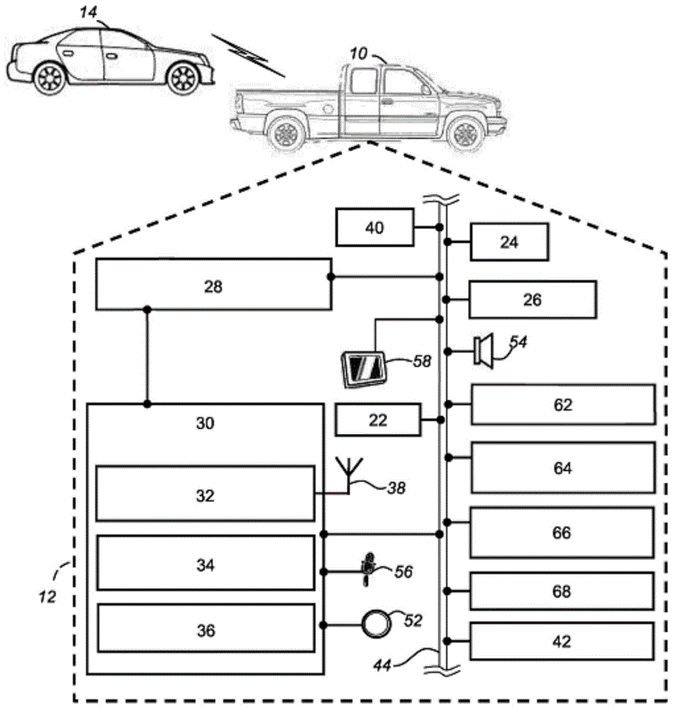
FIG. 1 is a block diagram depicting an embodiment of a system capable of utilizing the methods disclosed herein;
FIG. 2 is a schematic diagram of an exemplary electronic display mirror that may be used with the system of FIG. 1 during a first scene occurrence;
FIG. 3 is a schematic diagram of an exemplary electronic display mirror that may be used with the system of FIG. 1 during a second scene occurrence;
FIG. 4 is a schematic diagram of an exemplary electronic display mirror that may be used with the system of FIG. 1 during a third scene occurrence; and
FIG. 5 is a flow chart of an exemplary method of displaying an image on an electronic display included in a vehicle.
Detailed Description
The systems and methods described below enable a vehicle to display a plurality of images on an electronic display included in the vehicle. The electronic display may be used to display images for viewing by a vehicle operator. The images may be received from a control unit and/or other vehicle system modules via a communication bus. In some embodiments, the electronic display may be an electronic display mirror mounted in the vehicle and may display images received from a rear-facing video camera mounted on the vehicle and facing the area behind the vehicle. The control unit may be adapted to generate a primary image and one or more secondary images for display on the electronic display. The control unit may also receive sensor signals and/or may monitor vehicle state parameters (e.g., the position of external objects) as defined below. Based on the received sensor signals and/or the monitored vehicle state parameters, the control unit may determine whether to display certain images (e.g., primary or secondary images) on the electronic display. Additionally, the location of the image and other display characteristics (e.g., degree of transparency, size) may be determined based on the received sensor signals and/or the monitored vehicle state parameters. In some embodiments, secondary images may be overlaid on the primary image, and these secondary images may be positioned and/or altered to reduce interference with an object (such as another vehicle) displayed in the primary image.
Referring now to FIG. 1, a vehicle 12 having a vehicle electronics system 12 that may be used to implement the methods disclosed herein is shown. The vehicle electronics system 12 generally includes an electronic display in the form of an electronic display mirror 28 and a control unit 30. It should be understood that the disclosed methods may be used with any number of different systems and are not particularly limited to the operating environments shown herein. Moreover, the architecture, construction, arrangement, and operation of the system 12 and its various components are generally known in the art. Thus, the following paragraphs briefly outline one such vehicle electronic system 12; however, other systems not shown here may also employ the disclosed methods.
The vehicle 10 is depicted in the illustrated embodiment as a passenger vehicle, but it should be understood that any other vehicle including motorcycles, trucks, Sport Utility Vehicles (SUVs), Recreational Vehicles (RVs), marine vessels, aircraft, and the like, may be used. Some of the vehicle electronics 20 are shown generally in FIG. 1 and include an electronic display mirror 28, a control unit 30, a Body Control Module (BCM)40, a GPS module 22, a vehicle-to-vehicle (V2V) unit 24, sensors 26, other VSMs 42, vehicle user interfaces 52-58, cameras 62-68, and many other components and devices. Some or all of the various vehicle electronics may be connected via one or more communication buses, such as bus 44, to enable intercommunication, but any operable connection system or type may be used.
The vehicle 12 may include a plurality of Vehicle System Modules (VSMs) as part of the vehicle electronics system 12, such as a GPS module 22, an Engine Control Unit (ECU) (not shown), sensors 26, an electronic display mirror 28, a control unit 30, a Body Control Module (BCM)40, vehicle user interfaces 52-58, and cameras 62-68, as will be described in detail below. The vehicle 12 may also include other VSMs 42 in the form of electronic hardware components located throughout the vehicle and that may receive input from one or more sensors and use the sensed input to perform diagnostic, monitoring, control, reporting, and/or other functions. For example, other VSMs may include a telematics unit, a center console module (CSM), an infotainment unit, a powertrain control module, or a transmission control unit. Each VSM 42 may be connected to other VSMs and to control unit 30 (directly low and/or via bus 44) via communication bus 44 and may be programmed to run vehicle system and subsystem diagnostic tests. As will be appreciated by those skilled in the art, the VSMs described above are merely examples of some of the modules that may be used in the vehicle 12, as many other modules are possible.
A Global Positioning System (GPS) module 22 receives radio signals from a GPS constellation (not shown). GPS module 22 may provide such location data to control unit 30, and control unit 30 may then use the data to identify a known location, such as the vehicle operator's home or work place. In addition, the GPS module 22 may be used to provide navigation and other location-related services to the vehicle operator. The navigation information may be presented on the electronic display 28 and/or the display 58 (or other display within the vehicle) in the form of a primary or secondary image that includes one or more graphics or the like. Alternatively, the navigation information may be presented in a voice manner, for example, as is done when providing turn-by-turn navigation. The navigation service may be provided using a dedicated in-vehicle navigation module (which may be part of the GPS module 22) or some or all of the navigation service may be accomplished by a telematics unit installed in the vehicle, where the location information is transmitted to a remote location for the purpose of providing a navigation map, map annotations (points of interest, restaurants, etc.), route calculations, etc. for the vehicle. The GPS module 22 may be used as a sensor to provide input relating to nearby objects or vehicles for use with the methods described herein.
Vehicle-to-vehicle (V2V) unit 24 is a wireless communication device that enables host vehicle 12 to communicate with one or more nearby vehicles of similar configuration according to a V2V communication hierarchy, such as a V2V communication connection between two V2V-enabled vehicles, V2V. The V2V cell 24 may be used as a sensor to provide input related to a nearby object or vehicle, such as vehicle 14, for use with the methods described herein.
The vehicle sensors 26 provide sensor inputs to the vehicle including various sensor readings, measurements, and/or other information that may be used to perform the present method. For example, the vehicle sensors 26 may include sensors or other components for measuring: the presence of the object 14 around the vehicle blind spot, the absolute velocity of the vehicle, the position of the object 14 relative to the vehicle, the velocity of the object 14 relative to the vehicle, the absolute velocity of the object 14, the wheel velocity of the vehicle, the wheel acceleration of the vehicle, the vehicle velocity, the vehicle acceleration (longitudinal and/or lateral), the yaw rate of the vehicle, the steering wheel angle of the vehicle, other vehicle dynamics, and also including other sensors known in the art but not mentioned herein. The sensors 26 may utilize a variety of different sensor types and technologies, including RADAR devices, laser devices, LIDAR devices, ultrasound devices, vision devices (such as cameras, etc.), devices for receiving communications from wayside beacons or sensors, other known devices, or combinations thereof, as well as devices that use rotating wheel speed, ground speed, accelerometers, Inertial Measurement Units (IMUs), accelerator pedal position, shifter selection, engine speed, engine output, throttle position, steering wheel angle, to name a few. Those skilled in the art will recognize that the sensors may operate according to optical, electromagnetic, and/or other techniques, and that other parameters may be derived or calculated from these readings (e.g., acceleration may be calculated from velocity). The sensors 26 may be embodied in hardware, software, firmware, or some combination thereof, and these sensors may directly sense or measure the conditions that provide them, or they may indirectly evaluate these conditions based on information provided by other sensors, components, devices, modules, systems, etc. Any of the various sensor readings described below may be provided by some other component, device, module, system, etc. in the host vehicle 12, rather than by the actual sensor elements. It should be appreciated that the foregoing scenarios represent only some of the possibilities, as the present systems and methods are not limited to any particular sensor or arrangement of sensors.
The electronic display mirror 28 is an electronic display and includes a video display integrated into the rearview mirror unit or housing such that the display displays the video output from the rear-view camera 62 and other graphics or images (e.g., images from cameras 64-68) to the driver in real-time. As used herein, an electronic display may be any display capable of presenting images, video, graphics, etc., based on received electronic signals. It should be understood that as used herein, "image" may include still images, real-time or recorded video, graphics, and the like. According to the exemplary embodiment of fig. 1, electronic display mirror 28 is coupled to control unit 30 and receives enhanced video output from control unit 30. The electronic display mirror may utilize any number of different display technologies, such as a Liquid Crystal Display (LCD) or a Light Emitting Diode (LED) display. It should be appreciated that the systems and methods described herein may use any suitable type of electronic display mirror 28 and are not limited to any particular one. For example, the electronic display 28 may be a Full Display Mirror (FDM), wherein the entire viewable surface of the device displays video from one of the cameras 62-68; the electronic display mirror may be of the type: wherein only a portion of the display surface displays video from one of the cameras 62-68 while other portions of the display surface display other information (e.g., turn-by-turn navigation or other navigation instructions, compass or heading information, host vehicle performance data, etc.); the electronic display mirror can be provided with a day mode and a night mode to adjust the brightness correspondingly; or it may have a touch screen so that the user can make selections or enter data, to name just a few possibilities. Instead of the electronic display mirror 28 being positioned in the traditional location of the rear view mirror (i.e., mounted at the mid-up position of the front windshield), the electronic display mirror 28 may be part of a center console infotainment or rear standby display, or may be part of some other display. The systems and methods described herein are particularly applicable to electronic display mirrors because the size of the mirrors is typically smaller than other vehicle display units. Further, because the electronic display mirror may provide the driver with very useful information regarding the vehicle surroundings, the systems and methods herein may allow for efficient and advantageous presentation of such information.
The electronic display mirror 28 may be used to view one or more objects behind the vehicle, such as the target object 14. The object 14 is depicted in the illustrated embodiment as a passenger car, but it should be understood that the object 14 may be any other identifiable object, such as a pedestrian, a building, or a traffic cone. In embodiments where the object 14 is another vehicle, this other vehicle 14 may communicate with the vehicle 12 via V2V communication or other communication (e.g., cellular, SRWC). In addition, there may be more than one object 14.
The control unit 30 may be at least partially responsible for carrying out or completing one or more of the methods described below. In a preferred embodiment, the control unit 30 may be a video control unit dedicated to receiving and processing input from one or more vehicle cameras (e.g., cameras 62-68) and providing output to one or more vehicle devices (e.g., electronic display mirror 28). Alternatively, control unit 30 may be part of or used by one or more other vehicle systems, such as an active safety system, to name just one example. As shown in the exemplary embodiment of fig. 1, control unit 30 includes a Wireless Access Point (WAP)32, a processor 34, a memory 36, and one or more antennas 38 (only one shown). In other embodiments, control unit 30 may not include a wireless access point, but may include a modem, an ethernet port, or other hardware that may be used to enable wired communication over communication bus 44. According to an exemplary embodiment, control unit 30 is coupled to cameras 62-68 and receives video inputs, to V2V unit 24 and receives traffic inputs, to vehicle sensors 26 and receives sensor inputs, to GPS module 22 and receives navigation inputs, and to electronic display mirror 28 and provides video outputs, although other combinations of devices may be coupled to the control unit. Any of these connections may be made via communications bus 44, via WAP 32, and/or via any other operable direct or indirect connection method. Control unit 30 may include any kind of electronic processing device, memory device, input/output (I/O) device, and/or other known components and may perform various control and/or communication related functions.
In the exemplary embodiment, control unit 30 includes an electronic memory device 36 that can receive and store any combination of the following: image or video data from cameras 62-68, information about nearby vehicles from V2V unit 24, sensor readings from vehicle sensors 26, location or heading data from GPS module 22, a look-up table or other data structure, an algorithm (e.g., an algorithm embodied in the exemplary method described below), etc. The memory device 36 may also store relevant characteristics and contextual information related to the host vehicle 12, such as information related to vehicle dimensions (e.g., weight, width, and length), stopping distance, driver behavior or historical data, particular sensor or camera positions and orientations on the host vehicle 12, and so forth. The control unit 30 may also include an electronic processing device 34 (e.g., a microprocessor, microcontroller, Application Specific Integrated Circuit (ASIC), etc.) that executes instructions of software, firmware, programs, algorithms, scripts, applications, etc., stored in a memory device 36 and that may manage the methods described herein. The control unit 30 may be electrically connected to other vehicle devices, modules and systems via suitable vehicle communications (e.g., CAN bus, etc.) and may interact with them as needed. Of course, these are just some of the possible arrangements, functions and capabilities of the control unit 30, as other embodiments may also be employed.
In some embodiments, control unit 30 is capable of communicating data via short-range wireless communication (SRWC). In many embodiments, the control unit 30 may be specially configured to perform the methods disclosed herein. In one embodiment, control unit 30 may be a stand-alone module, or in other embodiments, device 30 may be incorporated or included as part of one or more other vehicle system modules, such as a center console module (CSM), a body control module, an infotainment module, a telematics module, a head unit, and/or a gateway module. In some embodiments, control unit 30 may be implemented as an OEM-installed (embedded) or after-market device installed in a vehicle.
According to one embodiment, cameras 62-68 (and more specifically rear facing camera 62) may provide video data in which images (e.g., images that make up the video data) are flipped horizontally (i.e., they are mirror images of the video originally captured by the camera). The horizontally flipped video data illustrates the following fact: the cameras 62-68 and the driver face in opposite directions, allowing video data to be presented on the electronic display mirror 28 in an orientation consistent with conventional rear view mirrors and rear facing side views. Some non-limiting examples of potential embodiments or features that may be used with cameras 62-68 include: infrared LEDs for night vision; wide-angle or fisheye lenses; surface mount, flush mount, license plate mount or side mount cameras; a stereoscopic arrangement having a plurality of cameras; a camera integrated into a tail light, brake light or other component of the rear end of the vehicle; and wired or wireless cameras, to name just a few possibilities.
Cameras 62-68 may transmit or transmit video or image data to control unit 30. For example, the rear facing camera 62 may continuously transmit video data to the control unit 30 when the ignition or main propulsion system of the vehicle is turned on or activated. In addition, blind spot cameras 64 and 66 may transmit or send video data of the left and right blind spots to control unit 30. The auxiliary (or car) camera 68 may also send video data to the control unit 30. The video data may be interlaced or progressive type video data or interlaced type video data to the control unit 30. The control unit may then decode, convert, or otherwise process the video data so that the encoded video in the data may be properly displayed on the electronic display mirror 28, visual display 58, or other display. For example, if the electronic display mirror is to be configured to display progressive type video and the video data received at the control unit is to be interlaced type video data, the interlaced type video data may be de-interlaced at the control unit so that the interlaced type video received from the cameras 62-68 may be placed in the correct progressive type format so that the electronic display mirror 28 may properly display the video data. Other image processing may be performed by the processor 34 or other processing devices in the vehicle 12, many of which are well known to those skilled in the art.
As will be discussed in more detail below, one or more images or other graphics may be displayed on the electronic display mirror, and such images or graphics may be displayed based on certain sensor data or video/image data received from cameras 62-68. For example, the processor may identify certain objects, such as objects that may be located behind the vehicle 12 or other vehicles 14, by using image processing techniques. In one embodiment, the control unit 30 may use image processing software that may distinguish certain objects in the captured images and, by analyzing a series of images and possibly combining information from one or more vehicle sensors (such as sensor 36), may determine the position, distance, speed, and/or acceleration of these distinguished objects relative to the vehicle 12. Alternatively, the video feed may determine that certain objects (such as another vehicle 14) may be objects of interest to the vehicle operator, and thus, video depicting those objects may be preferentially displayed on the electronic display mirror 28.
As shown in fig. 1, any of the devices 22-68 may be standalone, or they may be incorporated or included within some other device, unit, or module (e.g., the V2V unit 24 may be included within another vehicle communication module, some of the sensors 26 may be packaged in an Inertial Measurement Unit (IMU), the GPS module 22 may be part of a telematics unit, and the control unit 30 may be integrated with the electronic display mirror 28 or dashboard control module, etc.). Further, as shown in FIG. 1, any of the devices 22-68 may be dedicated, or they may be part of or shared by other systems or subsystems in the vehicle (e.g., the cameras 62-68 and/or some of the sensors 26 may be part of an active safety system, an anti-lock braking system (ABS), or an autonomous or semi-autonomous driving system; the electronic display mirror 28 or control unit 30 may be part of a vehicle infotainment system, etc.). The video, traffic, sensor, and/or navigation inputs from devices 22-68 may be provided directly to control unit 30, or indirectly through some other device, module, and/or system, as is generally known in the art. Similarly, enhanced video output from the control unit 30 may be provided directly or indirectly to the electronic display mirror 28. Thus, as long as the devices 22-68 can be used with the methods described herein, they are not limited to the schematic diagram in fig. 1 or the exemplary description above, nor to any particular embodiment or arrangement.
Referring to fig. 2-4, three scenarios 100, 110, and 120 are shown. These scenarios show the electronic display mirror 28 with a primary image 102 and a secondary image 104, and illustrate different ways in which the method may integrate or position the images relative to each other. Primary image 102 may include video data from rear facing camera 62 while secondary image 104 may include video data from another image source, which as shown may be an image or video of the vehicle cabin from secondary camera 68. The primary and/or secondary images may be modified or altered based on various vehicle conditions, sensor signals, navigation information, image processing results of video data received from cameras 62-68, or other data or information obtained by vehicle 12. Additionally, different types of vehicles may include cameras positioned at different areas in and/or around the vehicle. For example, a car may have an auxiliary camera 68 positioned at the rear seat area of the vehicle, while a pick-up truck may have an auxiliary camera 68 positioned at the cabin area. The exemplary method 200 depicted in FIG. 5 will be discussed with reference to scenarios 100, 110, and 120.
Referring to fig. 5, an exemplary embodiment of a method 200 of displaying an image on an electronic display included in a vehicle is shown. In some embodiments, the method 200 includes the steps of: the method includes receiving sensor signals from one or more sensors located on the vehicle, generating and displaying a primary image on the electronic display mirror, and then generating and displaying the primary and secondary images or graphics on the electronic display mirror based on the received sensor signals. The method 200 may be performed by the control unit 30 and/or any other suitable vehicle module included in the vehicle 12, such as the VSM 42.
The method 200 starts with step 210, wherein a primary image 102 to be displayed on an electronic display comprised in a vehicle is generated, as shown in fig. 2 to 4. The main image may be a real-time or recorded video or an image from a video frame, such as an image generated from an interlaced or progressive scan type video. Preferably, the primary image 102 is a rear view of an area behind the vehicle 12 displayed on the electronic display mirror 28, and in the illustrated embodiment, the electronic display mirror 28 shows the object 14 behind the vehicle 12. When the vehicle is placed in a start-up condition such that the ignition or the main propulsion system is activated, the electronic display mirror 28 may display images received from the rear facing camera 62. The received video data may be horizontally flipped so that the displayed image functions similar to a conventional rear view mirror. In other embodiments, the primary image may be composed of graphics, other images, or renderings. The method 200 proceeds to step 220.
In step 220, sensor signals from one or more sensors located on the vehicle 12 or at the vehicle 12 are received. The one or more sensors may be vehicle sensors 26, cameras 62-68, V2V unit 24, GPS 22, engine control unit, BCM 40, other VSMs 42 that obtain sensory inputs, microphone 56, buttons 52 (as shown in fig. 1), or any other device that may provide information to the vehicle regarding the vehicle's state (e.g., operating state, other physical characteristics of the vehicle, vehicle module electronic or logical state), environmental conditions of the area surrounding the vehicle, and/or external characteristics of the area surrounding the vehicle (e.g., the presence of other vehicles, pedestrians, electronic devices, or objects around or within the vehicle).
Additionally or alternatively, one or more sensors included on or at the vehicle may be used to monitor the vehicle state parameter. The vehicle state parameter may be or may be based on one or more of a state, condition, and/or characteristic of the vehicle and/or a surrounding environment of the vehicle. For example, the vehicle state parameters may include or may be based on an operating state, other physical characteristics of the vehicle (e.g., absolute speed of the vehicle 12, position of the object 14 relative to the vehicle 12, position of the object 14 as shown in the master image, size of the object 14 relative to the master image, speed of the object 14 relative to the vehicle 12, and absolute speed of the object 14), vehicle module electronic or logical states, environmental conditions of an area surrounding the vehicle, and/or external characteristics of an area surrounding the vehicle (e.g., presence of other vehicles, pedestrians, electronic devices, or objects around or within the vehicle).
The received sensor signals and/or the monitored vehicle state parameters may be stored in the memory 36 of the control unit 30 and/or may be processed by the processor 34. As will be discussed further below (see step 240), the control unit may use the received sensor signals and/or the detected vehicle state to determine whether, where, and/or how to display certain secondary images on the electronic display mirror 28. In certain embodiments, step 210 may be performed before step 220, and the generation of the primary image may be based on the received sensor signals and/or the monitored vehicle state parameters. The method 200 proceeds to step 230.
In step 230, a secondary image 104, for example as shown in fig. 2-4, is generated, and in some embodiments, may be generated based on the monitored vehicle state and/or received sensor signals. The secondary image 104 may be an image similar to the primary image, but may be generated from video data received from a different camera. For example, the secondary images may be generated from video data received from the auxiliary camera 68, which may include images of the cabin of the vehicle 12. In other embodiments, the secondary images may include renderings using pre-stored graphics/image files (e.g., stored on memory 36), such as renderings of an overhead view of the vehicle 12, one or more graphics, or images obtained from one or more cameras in the vehicle. As will be described in more detail below, the rendering may be based on data received from one or more sensors (e.g., sensor 26) or cameras 62-68.
In some embodiments, a number of secondary images are generated. For example, a first sub-image may be generated to depict an area of a blind area on the left side of the vehicle, and a second sub-image may be generated to depict an area of a blind area on the right side of the vehicle. The two sub-images may then be displayed simultaneously on the electronic display mirror, as will be described below in step 240. In some embodiments, the vehicle may determine to display one or more secondary images based on the received sensor signals or the monitored vehicle state parameters.
In some embodiments, the secondary image may not be generated based on the monitored vehicle state parameters or based on the received sensor signals. For example, if a collision with the object 14 is likely, the method may determine that only the primary image 102 should be displayed to provide a clearer or less obstructed image to the driver. In such embodiments, the method 200 may end or may return to step 210 or 220. Otherwise, the method 200 may proceed to step 240.
In step 240, a primary image and a secondary image are displayed on the electronic display, wherein the secondary image is overlaid on the primary image at a position based at least in part on the received sensor signal. As used herein, "overlaying" may include blending two images, placing one image in a specified subset of the available screen space and resizing the other image accordingly, placing one image on top of the other, or any other operable method of spatially including two images within a specified area (possibly blocking one or more portions of one or more images). In one embodiment, the primary image may cover a substantial (or the entire) portion of the electronic display mirror, while the secondary image may be placed over the primary image. In other embodiments, the primary image may cover some designated or determined area of the electronic display. The designated area may be an area of the electronic display reserved for the main image (e.g., a relatively large portion of the middle of the electronic display). The determined area may be an area of the electronic display determined to be on which the primary image is to be displayed and may be based on monitored vehicle status parameters or received sensor signals.
For example, referring back to fig. 2, the received sensor signal may detect or be used to detect that the other vehicle 14 is more to the left of the primary image 102 than to the right of the primary image 102. This may be determined based on image processing and object recognition techniques, and/or may be based on other sensor signals, such as blind spot detectors or vehicle information received via the V2V cell 24. When the other vehicle 14 is determined to be to the left of the vehicle 12 in the object region 106, the secondary image 104 may be superimposed at a position 108 to the right of the primary image 102 so as not to interfere with (or reduce interference with) the depiction of the vehicle 14. Alternatively, when the vehicle 14 is determined to be on the left side of the vehicle 12 and the vehicle 14 is at least partially depicted in the primary image 102, then the secondary image 104 may be superimposed on the right side of the primary image 102. The same may also apply to the case where the other vehicle 14 is determined to be located to the right and/or displayed at least partially to the right of the primary image 102, except that the secondary image 104 will be displayed at a position 108 that is now to the left of the electronic display mirror 28, as shown in fig. 3. For example, if the vehicle 14 passes through a middle point, the secondary image 104 may move to a position 108 on the other side of the display 28. Further, the size of the secondary image 104 may be related to the position 108 of the secondary image, and the position 108 may depend on the object region 106. Although fig. 2-4 illustrate other vehicles 14 passing in an area behind the vehicle, oftentimes another vehicle is towed behind the host vehicle, another object (e.g., a pedestrian, etc.) is present, and/or one or more stationary objects are present. Any target object may affect the position, size, quality, etc. of the secondary image, depending on the desired implementation.
Additionally or alternatively, one or more characteristics of the secondary image may be altered based at least in part on the vehicle state parameter and/or the received sensor signal. In some embodiments, doing so may allow the user to better discern certain aspects depicted in the primary image. For example, where other vehicles or objects 14 are displayed on the primary image 102 and the object region 106 occupies a substantial portion of the image 102, there may not be a location to display the secondary image if portions of the object 14 are not removed. In this case, the secondary image 104 may be displayed provided that the object region 106 and the position 108 of the secondary image at least partially overlap, but the transparency of the secondary image may be adjusted (e.g., such that the secondary image is partially transparent), as shown in fig. 4. The adjustment of the transparency of the secondary image or other change of the secondary image may be based on vehicle state parameters and/or received sensor signals. For example, the transparency may be adjusted based on the relative speed of the object depicted in the main image and/or the position of the object depicted in the main image. For example, if the object region 106 occupies 75% or more of the total screen area, the transparency level of the secondary image 104 may be adjusted to between 25% and 75%, or more specifically 50%. Alternatively, if, for example, the act of resizing the secondary image produces a secondary image that is too small (e.g., about 10% or less of the total area of the screen), it may be more desirable to change the level of transparency and keep the image size at the standard illustration size. The altered characteristic of the secondary image may also include the position of the secondary image and/or the size of the secondary image. Other graphics and/or image changes may be made, such as changing size, hue, saturation, position, transparency, brightness, contrast, color, curve, hue, darkness, color value, intensity, brightness, shape, color set or thresholds (e.g., black and white, grayscale, 8-bit color), hue separation, color balance, exposure, gradation, channel, and/or vibrancy.
Other types of secondary images may be generated and/or obtained that may be displayed on the electronic display mirror 28. For example, certain vehicle characteristics (e.g., an absolute speed of the vehicle 12, a position of the object 14 relative to the vehicle 12, a position of the object 14 as depicted in the primary image, a size of the object 14 relative to the primary image, a speed of the object 14 relative to the vehicle 12, and an absolute speed of the object 14) may be generated to be displayed graphically as the secondary image or as part of the secondary image and/or the primary image. Additionally, other metrics or conditions may be generated and/or obtained for display, such as environmental metrics (e.g., outside temperature, cabin temperature, predicted weather).
In other embodiments, multiple secondary images may be displayed on the electronic display mirror simultaneously. One or more of these secondary images may be overlaid over the primary image (e.g., picture-in-picture (PIP)). In one embodiment, the electronic display may be divided along the middle (e.g., 50/50 divisions forming left and right sides of equal area). The primary image may then be displayed on the left side and the secondary image may then be displayed on the right side. The electronic display may be divided in different scales, for example 60/40 division for the main/secondary image, or 20/60/20 division for the first/main/second secondary image. In one embodiment, the primary image may be an image from rear facing camera 62, the first secondary image may be an image from left blind spot camera 64, and the second secondary image may be an image from right blind spot camera 66. When it is detected that no object (such as the vehicle 14) is located in the left and/or right blind spot and/or in the primary image of the vehicle 12, the first and/or second secondary image may be removed and the space re-planned accordingly.
The primary and secondary images may then be displayed on the electronic display mirror 28. The final image, which is a composite of the primary and secondary images, may be generated by the control unit 30 and then sent to the electronic display mirror 28 via the bus 44. The final image may be a single aggregate image generated based on the determinations made above with respect to the characteristics, size, positioning, and/or other display attributes of the primary and secondary images. Once the final image is received, it is displayed by the electronic display mirror 28. The electronic display mirror may display other textual or graphical information on the final image. Alternatively or additionally, the electronic display mirror may display the final image according to other metadata received with the final image or according to other instructions received at the electronic display mirror 28. Thereafter, the method 200 ends.
It is to be understood that the foregoing description is not a definition of the invention, but is a description of one or more preferred exemplary embodiments of the invention. The present invention is not limited to the specific embodiments disclosed herein, but only by the following claims. Furthermore, the statements contained in the foregoing description relate to particular embodiments and are not to be construed as limitations on the scope of the invention or on the definition of terms used in the claims, except where a term or phrase is expressly defined above. Various other embodiments as well as various changes and modifications to the embodiments disclosed above will be apparent to those skilled in the art. For example, the particular combination and order of steps is only one possibility, as the method may include combinations of steps having fewer, more, or different steps than those shown. All such other embodiments, changes and modifications are intended to fall within the scope of the appended claims.
As used in this specification and claims, the terms "such as," for example, "" such as, "" and "like," and the verbs "comprising," "having," "including," and their other verb forms, when used in conjunction with a listing of one or more components or other items, are each to be construed as open-ended, meaning that listing is not to be considered as excluding other, additional components or items. Other terms are to be construed using their broadest reasonable meaning unless they are used in a context that requires a different interpretation. Additionally, the term "and/or" should be interpreted as an inclusive or. In other words, the phrase "A, B and/or C" includes: "A"; "B"; "C"; "A and B"; "A and C"; "B and C"; and "A, B and C".
Claims (8)
1. A method of displaying an image on an electronic display included in a vehicle, the method comprising:
generating a primary image for display on the electronic display included in the vehicle;
receiving sensor signals from one or more sensors located on or at the vehicle;
determining whether the object is located within a left area corresponding to a left portion of the main image or a right area corresponding to a right portion of the main image based on the sensor signal;
generating a secondary image for display on the electronic display; and
displaying the primary image on the electronic display and the secondary image on the electronic display, wherein the secondary image is overlaid on the primary image at a position based at least in part on the received sensor signal, and wherein:
the sub-image is superimposed on a right side portion of the main image when the object is located within the left region, an
When the object is located within the right region, the sub-image is superimposed on the left portion of the main image.
2. The method of claim 1, wherein the primary image is generated from a rear facing camera and the electronic display is an electronic display mirror.
3. The method of claim 1, wherein the primary image or the secondary image is part of a streaming video feed.
4. The method of claim 1, further comprising the steps of: detecting that an object is depicted in the primary image using the received sensor signals, and based on the detecting, determining a position on the primary image overlying the secondary image.
5. The method according to claim 4, wherein the detecting step further comprises determining an area on the primary image depicting the object, and wherein the position on the primary image overlying the secondary image is based on the area on the primary image where the object is detected.
6. The method according to claim 5, wherein the location on the primary image overlying the secondary image and the area on the primary image depicting the object are completely separate from each other.
7. The method of claim 1, wherein the secondary image is generated by a camera facing one or more of the following regions: a rear seat of the vehicle, a compartment of the vehicle, a blind spot of the vehicle, an interior region of a trunk, or an interior region of a trailer.
8. A system for displaying images in a vehicle, the system comprising:
one or more sensors located on or at the vehicle;
a rear facing camera configured to generate a primary image;
a second camera configured to generate a secondary image;
an electronic display mirror configured to display the primary image from the rear facing camera and the secondary image from the second camera; and
a control unit connected to the one or more sensors, the rear facing camera, the second camera, and the electronic display mirror, wherein the control unit is configured to:
receiving sensor signals from the one or more sensors located on or at the vehicle;
determining whether the object is located within a left area corresponding to a left portion of the main image or a right area corresponding to a right portion of the main image based on the sensor signal; and
displaying the primary image on the electronic display mirror and the secondary image on the electronic display mirror, wherein the secondary image is overlaid on the primary image at a location based at least in part on the received sensor signal, and wherein: the sub-image is superimposed on a right side portion of the main image when the object is located within the left region, and the sub-image is superimposed on a left side portion of the main image when the object is located within the right region.
Applications Claiming Priority (2)
| Application Number | Priority Date | Filing Date | Title |
|---|---|---|---|
| US15/466,604 US10609339B2 (en) | 2017-03-22 | 2017-03-22 | System for and method of dynamically displaying images on a vehicle electronic display |
| US15/466604 | 2017-03-22 |
Publications (2)
| Publication Number | Publication Date |
|---|---|
| CN108621943A CN108621943A (en) | 2018-10-09 |
| CN108621943B true CN108621943B (en) | 2021-09-28 |
Family
ID=63450008
Family Applications (1)
| Application Number | Title | Priority Date | Filing Date |
|---|---|---|---|
| CN201810185721.2A Active CN108621943B (en) | 2017-03-22 | 2018-03-07 | System and method for dynamically displaying images on a vehicle electronic display |
Country Status (3)
| Country | Link |
|---|---|
| US (1) | US10609339B2 (en) |
| CN (1) | CN108621943B (en) |
| DE (1) | DE102018105951B4 (en) |
Families Citing this family (15)
| Publication number | Priority date | Publication date | Assignee | Title |
|---|---|---|---|---|
| WO2019150918A1 (en) * | 2018-02-02 | 2019-08-08 | ソニー株式会社 | Information processing device, information processing method, program, and moving body |
| US11176215B2 (en) * | 2018-07-23 | 2021-11-16 | International Business Machines Corporation | Navigational notifications based on filtered interests |
| DE102018128634A1 (en) * | 2018-11-15 | 2020-05-20 | Valeo Schalter Und Sensoren Gmbh | Method for providing visual information about at least part of an environment, computer program product, mobile communication device and communication system |
| US11302182B2 (en) * | 2018-12-28 | 2022-04-12 | Beijing Voyager Technology Co., Ltd. | Systems and methods for vehicle identification |
| WO2020198427A1 (en) * | 2019-03-27 | 2020-10-01 | Gentex Corporation | Selective display window for vehicle |
| CN110120110B (en) * | 2019-04-09 | 2021-11-23 | 深圳市麦谷科技有限公司 | Reversing image processing method and device, computer equipment and storage medium |
| RU2769360C1 (en) | 2019-05-15 | 2022-03-30 | Ниссан Мотор Ко., Лтд. | Display control method and display control device |
| US11055870B2 (en) * | 2019-07-24 | 2021-07-06 | Toyota Motor Engineering & Manufacturing North America, Inc. | Vehicle auxiliary camera |
| CN112136166B (en) * | 2019-09-04 | 2022-08-12 | 赵婷婷 | System and method for controlling a vehicle |
| US11995991B2 (en) * | 2020-12-22 | 2024-05-28 | Stack Av Co. | Shared control for vehicles travelling in formation |
| USD1012944S1 (en) | 2021-08-03 | 2024-01-30 | Icon Vehicle Dynamics Llc | Display screen with graphical user interface |
| USD1024092S1 (en) | 2021-08-03 | 2024-04-23 | Icon Vehicle Dynamics Llc | Display screen with graphical user interface |
| US11999386B2 (en) | 2022-01-31 | 2024-06-04 | Stack Av Co. | User interfaces for autonomy state control and alerts |
| CN116424249A (en) * | 2023-04-28 | 2023-07-14 | 重庆长安汽车股份有限公司 | Vehicle scene control method, system, electronic equipment and storage medium |
| DE102023210557A1 (en) * | 2023-10-25 | 2025-04-30 | Continental Automotive Technologies GmbH | Computer-implemented method for controlling a graphical user interface on a display of a vehicle |
Citations (4)
| Publication number | Priority date | Publication date | Assignee | Title |
|---|---|---|---|---|
| CN102740055A (en) * | 2011-04-01 | 2012-10-17 | 财团法人工业技术研究院 | Device and method for monitoring surrounding field |
| CN103770706A (en) * | 2012-10-19 | 2014-05-07 | 通用汽车环球科技运作有限责任公司 | Dynamic rearview mirror display features |
| CN105139389A (en) * | 2014-05-16 | 2015-12-09 | 通用汽车环球科技运作有限责任公司 | Surround-view camera system (vpm) and vehicle dynamic |
| WO2016026870A1 (en) * | 2014-08-18 | 2016-02-25 | Jaguar Land Rover Limited | Display system and method |
Family Cites Families (7)
| Publication number | Priority date | Publication date | Assignee | Title |
|---|---|---|---|---|
| JP2005223524A (en) * | 2004-02-04 | 2005-08-18 | Nissan Motor Co Ltd | Vehicle periphery monitoring device |
| US8633810B2 (en) * | 2009-11-19 | 2014-01-21 | Robert Bosch Gmbh | Rear-view multi-functional camera system |
| US10029621B2 (en) | 2013-05-16 | 2018-07-24 | Ford Global Technologies, Llc | Rear view camera system using rear view mirror location |
| US20160368418A1 (en) | 2014-04-01 | 2016-12-22 | Panasonic Intellectual Property Management Co., Ltd. | Rear-view monitor device and automobile equipeed with same |
| KR20190009801A (en) | 2016-05-24 | 2019-01-29 | 젠텍스 코포레이션 | Vehicle display with optional image data display |
| US20170374287A1 (en) | 2016-06-23 | 2017-12-28 | Werner Lang | System for Visually Depicting Fields of View of a Commercial Vehicle |
| US20180220082A1 (en) * | 2017-01-30 | 2018-08-02 | GM Global Technology Operations LLC | Method and apparatus for augmenting rearview display |
-
2017
- 2017-03-22 US US15/466,604 patent/US10609339B2/en active Active
-
2018
- 2018-03-07 CN CN201810185721.2A patent/CN108621943B/en active Active
- 2018-03-14 DE DE102018105951.5A patent/DE102018105951B4/en active Active
Patent Citations (4)
| Publication number | Priority date | Publication date | Assignee | Title |
|---|---|---|---|---|
| CN102740055A (en) * | 2011-04-01 | 2012-10-17 | 财团法人工业技术研究院 | Device and method for monitoring surrounding field |
| CN103770706A (en) * | 2012-10-19 | 2014-05-07 | 通用汽车环球科技运作有限责任公司 | Dynamic rearview mirror display features |
| CN105139389A (en) * | 2014-05-16 | 2015-12-09 | 通用汽车环球科技运作有限责任公司 | Surround-view camera system (vpm) and vehicle dynamic |
| WO2016026870A1 (en) * | 2014-08-18 | 2016-02-25 | Jaguar Land Rover Limited | Display system and method |
Also Published As
| Publication number | Publication date |
|---|---|
| DE102018105951A1 (en) | 2018-09-27 |
| US10609339B2 (en) | 2020-03-31 |
| CN108621943A (en) | 2018-10-09 |
| US20180272944A1 (en) | 2018-09-27 |
| DE102018105951B4 (en) | 2019-07-04 |
Similar Documents
| Publication | Publication Date | Title |
|---|---|---|
| CN108621943B (en) | System and method for dynamically displaying images on a vehicle electronic display | |
| US12087061B2 (en) | Vehicular control system | |
| AU2016283002B2 (en) | Augmented reality system for vehicle blind spot prevention | |
| CN112349256B (en) | Display control device, display control method, and storage medium | |
| US10410514B2 (en) | Display device for vehicle and display method for vehicle | |
| CN107054218A (en) | identification information display device and method | |
| US11256088B2 (en) | Vehicle display device | |
| US20190389385A1 (en) | Overlay interfaces for rearview mirror displays | |
| EP3508908B1 (en) | Vehicle display device | |
| JP2022140026A (en) | Image processing device, image processing method and program | |
| JP7243516B2 (en) | Display controller and display control program | |
| US11748936B2 (en) | Using epipolar reprojection for virtual view perspective change | |
| US20190161007A1 (en) | Unilluminated vehicle indication based on communication | |
| US11770495B2 (en) | Generating virtual images based on captured image data | |
| WO2022210171A1 (en) | Vehicle display system, vehicle display method, and vehicle display program | |
| CN108297691B (en) | Method and system for providing notifications on a camera display of a vehicle | |
| US20250078525A1 (en) | Information processing device and information processing method | |
| JP7071905B2 (en) | Display device | |
| CN120122336A (en) | Head-up display device, display control method, device and storage medium, and vehicle |
Legal Events
| Date | Code | Title | Description |
|---|---|---|---|
| PB01 | Publication | ||
| PB01 | Publication | ||
| SE01 | Entry into force of request for substantive examination | ||
| SE01 | Entry into force of request for substantive examination | ||
| GR01 | Patent grant | ||
| GR01 | Patent grant |