CN108615978B - Method and device for adjusting antenna direction - Google Patents
Method and device for adjusting antenna direction Download PDFInfo
- Publication number
- CN108615978B CN108615978B CN201611138756.8A CN201611138756A CN108615978B CN 108615978 B CN108615978 B CN 108615978B CN 201611138756 A CN201611138756 A CN 201611138756A CN 108615978 B CN108615978 B CN 108615978B
- Authority
- CN
- China
- Prior art keywords
- sum
- cell
- aoa
- sampling points
- antenna
- Prior art date
- Legal status (The legal status is an assumption and is not a legal conclusion. Google has not performed a legal analysis and makes no representation as to the accuracy of the status listed.)
- Active
Links
- 238000000034 method Methods 0.000 title claims abstract description 42
- 238000005070 sampling Methods 0.000 claims description 85
- IPVQLZZIHOAWMC-QXKUPLGCSA-N perindopril Chemical compound C1CCC[C@H]2C[C@@H](C(O)=O)N(C(=O)[C@H](C)N[C@@H](CCC)C(=O)OCC)[C@H]21 IPVQLZZIHOAWMC-QXKUPLGCSA-N 0.000 claims description 23
- 238000004364 calculation method Methods 0.000 claims description 15
- 238000005259 measurement Methods 0.000 claims description 5
- 238000004422 calculation algorithm Methods 0.000 claims description 4
- 230000005855 radiation Effects 0.000 description 7
- 238000004891 communication Methods 0.000 description 4
- 238000004590 computer program Methods 0.000 description 4
- 238000010586 diagram Methods 0.000 description 3
- 239000012141 concentrate Substances 0.000 description 2
- 230000000694 effects Effects 0.000 description 2
- 238000009434 installation Methods 0.000 description 2
- 238000010295 mobile communication Methods 0.000 description 2
- 230000003287 optical effect Effects 0.000 description 2
- 230000005540 biological transmission Effects 0.000 description 1
- 230000015556 catabolic process Effects 0.000 description 1
- 230000001413 cellular effect Effects 0.000 description 1
- 238000006731 degradation reaction Methods 0.000 description 1
- 238000012986 modification Methods 0.000 description 1
- 230000004048 modification Effects 0.000 description 1
- 238000005192 partition Methods 0.000 description 1
- 238000012360 testing method Methods 0.000 description 1
- 238000012546 transfer Methods 0.000 description 1
- 239000002699 waste material Substances 0.000 description 1
Images


Classifications
-
- H—ELECTRICITY
- H01—ELECTRIC ELEMENTS
- H01Q—ANTENNAS, i.e. RADIO AERIALS
- H01Q3/00—Arrangements for changing or varying the orientation or the shape of the directional pattern of the waves radiated from an antenna or antenna system
-
- H—ELECTRICITY
- H01—ELECTRIC ELEMENTS
- H01Q—ANTENNAS, i.e. RADIO AERIALS
- H01Q3/00—Arrangements for changing or varying the orientation or the shape of the directional pattern of the waves radiated from an antenna or antenna system
- H01Q3/26—Arrangements for changing or varying the orientation or the shape of the directional pattern of the waves radiated from an antenna or antenna system varying the relative phase or relative amplitude of energisation between two or more active radiating elements; varying the distribution of energy across a radiating aperture
- H01Q3/30—Arrangements for changing or varying the orientation or the shape of the directional pattern of the waves radiated from an antenna or antenna system varying the relative phase or relative amplitude of energisation between two or more active radiating elements; varying the distribution of energy across a radiating aperture varying the relative phase between the radiating elements of an array
-
- H—ELECTRICITY
- H04—ELECTRIC COMMUNICATION TECHNIQUE
- H04W—WIRELESS COMMUNICATION NETWORKS
- H04W16/00—Network planning, e.g. coverage or traffic planning tools; Network deployment, e.g. resource partitioning or cells structures
- H04W16/24—Cell structures
- H04W16/26—Cell enhancers or enhancement, e.g. for tunnels, building shadow
-
- Y—GENERAL TAGGING OF NEW TECHNOLOGICAL DEVELOPMENTS; GENERAL TAGGING OF CROSS-SECTIONAL TECHNOLOGIES SPANNING OVER SEVERAL SECTIONS OF THE IPC; TECHNICAL SUBJECTS COVERED BY FORMER USPC CROSS-REFERENCE ART COLLECTIONS [XRACs] AND DIGESTS
- Y02—TECHNOLOGIES OR APPLICATIONS FOR MITIGATION OR ADAPTATION AGAINST CLIMATE CHANGE
- Y02D—CLIMATE CHANGE MITIGATION TECHNOLOGIES IN INFORMATION AND COMMUNICATION TECHNOLOGIES [ICT], I.E. INFORMATION AND COMMUNICATION TECHNOLOGIES AIMING AT THE REDUCTION OF THEIR OWN ENERGY USE
- Y02D30/00—Reducing energy consumption in communication networks
- Y02D30/70—Reducing energy consumption in communication networks in wireless communication networks
Landscapes
- Engineering & Computer Science (AREA)
- Computer Networks & Wireless Communication (AREA)
- Signal Processing (AREA)
- Mobile Radio Communication Systems (AREA)
Abstract
本发明涉及一种天线方向调整方法及装置,该方法包括:采集小区内所有连接态的用户设备的信号来源方向;根据所有连接态的用户设备的信号来源方向,确定用户设备的集中区域的方向;根据用户设备的集中区域的方向,调整天线的方向,以使天线的电磁波能量集中在用户设备的集中区域。本发明实施例提供的技术方案,能够保证将天线电磁波能量集中于小区内用户集中的区域,能够最大化小区覆盖和流量价值,同时解决了现有天线调整方案中以道路为主,不考虑现网实际用户分布的问题,也解决了现有调整方案多依据工参和经验,效率不高精准度不高的问题。

The present invention relates to an antenna direction adjustment method and device. The method includes: collecting the signal source directions of all connected user equipments in a cell; and determining the direction of the concentrated area of the user equipment according to the signal source directions of all connected user equipments ; Adjust the direction of the antenna according to the direction of the concentrated area of the user equipment, so that the electromagnetic wave energy of the antenna is concentrated in the concentrated area of the user equipment. The technical solution provided by the embodiment of the present invention can ensure that the electromagnetic wave energy of the antenna is concentrated in the area where the users are concentrated in the cell, can maximize the coverage of the cell and the traffic value, and solve the problem that the existing antenna adjustment scheme mainly focuses on roads, regardless of the current situation. The problem of the distribution of actual users of the network also solves the problem that the existing adjustment scheme is mostly based on labor parameters and experience, and the efficiency is not high and the accuracy is not high.
Description
技术领域technical field
本发明涉及移动通信技术领域,尤其涉及一种天线方向调整方法及装置The present invention relates to the technical field of mobile communications, and in particular, to a method and device for adjusting antenna direction
背景技术Background technique
移动通信系统通常是蜂窝系统,其中,系统中的每个小区具有至少一个对应的关联基站,其具有至少一个天线,用来向/从该系统的用户设备终端发送和接收信号。A mobile communication system is typically a cellular system, wherein each cell in the system has at least one corresponding associated base station with at least one antenna for transmitting and receiving signals to/from user equipment terminals of the system.
基站天线被设计成使得从这种天线辐射的波束的倾斜角通常相对于水平面以一个角度向下偏转以便定义特定小区大小。然而,由于例如地理拓扑和/或存在建筑物,系统中的小区大小可能变化,并且基站天线的安装高度也可能变化。因此,必须根据天线所在的特定小区的大小以及天线的安装位置,将系统中不同天线的偏转角设置成不同的角度。Base station antennas are designed such that the angle of inclination of the beams radiated from such antennas is generally deflected downward at an angle relative to the horizontal in order to define a particular cell size. However, due to eg geographic topology and/or the presence of buildings, the cell size in the system may vary, and the installation height of the base station antennas may also vary. Therefore, the deflection angles of different antennas in the system must be set to different angles according to the size of the specific cell where the antenna is located and the installation position of the antenna.
现有技术方案中一般通过路测发现无线环境劣化点,其出发点在于改善道路无线环境质差点,提升RSRP(参考信号接收功率)及SINR(信干噪比),但基于路测得到的无线质量分析结果调整天线方向无法有效兼顾无线蜂窝小区内用户设备集中区域的覆盖,甚至可能出现小区天线主瓣方向明显偏离用户设备集中区域情况,造成用户设备价值的流失。另外,现有天线调整方案多依据工程参数和经验,属于人工操作,效率较低且精准度不高。In the prior art solution, the point of wireless environment degradation is generally found through drive tests. The starting point is to improve the poor quality of the road wireless environment, and to improve RSRP (Reference Signal Received Power) and SINR (Signal to Interference and Noise Ratio). The analysis results show that adjusting the antenna direction cannot effectively take into account the coverage of the user equipment concentrated area in the wireless cell, and even the main lobe direction of the cell antenna may deviate significantly from the user equipment concentrated area, resulting in the loss of user equipment value. In addition, the existing antenna adjustment schemes are mostly based on engineering parameters and experience, which are manual operations, with low efficiency and low accuracy.
发明内容SUMMARY OF THE INVENTION
本发明所要解决的技术问题是提供一种天线方向调整方法,解决现有的天线方向调整方法不考虑实际用户设备分布情况,造成流量浪费的问题。The technical problem to be solved by the present invention is to provide an antenna direction adjustment method, which solves the problem that the existing antenna direction adjustment method does not consider the actual distribution of user equipment, resulting in waste of traffic.
为此目的,本发明提出了一种天线方向调整方法,包括:For this purpose, the present invention provides an antenna direction adjustment method, including:
采集小区内所有连接态的用户设备的信号来源方向;Collect the signal source directions of all connected user equipments in the cell;
根据所述所有连接态的用户设备的信号来源方向,确定所述用户设备的集中区域的方向;Determine the direction of the concentrated area of the user equipment according to the signal source directions of all the user equipments in the connected state;
根据所述用户设备的集中区域的方向,调整所述天线的方向,以使所述天线的电磁波能量集中在所述用户设备的集中区域。Adjust the direction of the antenna according to the direction of the concentrated area of the user equipment, so that the electromagnetic wave energy of the antenna is concentrated in the concentrated area of the user equipment.
可选的,所述根据所有连接态的用户设备的信号来源方向,确定所述用户设备的集中区域的方向,具体包括:Optionally, the determining the direction of the concentrated area of the user equipment according to the signal source directions of all the user equipment in the connected state specifically includes:
根据所有连接态的用户设备的信号来源方向,确定信号来源方向的平均值;According to the signal source directions of all connected user equipments, determine the average value of the signal source directions;
根据所述信号来源方向的平均值,确定用户设备的集中区域的方向。According to the average value of the signal source directions, the direction of the concentrated area of the user equipment is determined.
可选的,所述根据所有连接态的用户设备的信号来源方向,确定所述用户设备的集中区域的方向,具体包括:Optionally, the determining the direction of the concentrated area of the user equipment according to the signal source directions of all the user equipment in the connected state specifically includes:
根据所有连接态的用户设备的信号来源方向,确定不同角度区间的用户设备数量;Determine the number of user equipments in different angle intervals according to the signal source directions of all connected user equipments;
根据所述不同角度区间的用户设备数量,确定用户设备数量最多的角度区间;According to the number of user equipments in the different angle intervals, determine the angle interval with the largest number of user equipments;
根据所述用户设备数量最多的角度区间,确定所述用户设备的集中区域的方向。The direction of the concentrated area of the user equipment is determined according to the angular interval with the largest number of user equipments.
可选的,根据所述所有连接态的用户设备的信号来源方向,确定所述用户设备的集中区域的方向,具体包括:Optionally, the direction of the concentrated area of the user equipment is determined according to the signal source directions of all the user equipments in the connected state, specifically including:
根据所有连接态的用户设备的信号来源方向,利用圆周旋转分片法在所述天线的主瓣方向处于不同方向时,分别计算所述主瓣方向覆盖区域内的用户设备的第一数量占所有连接态的用户设备的第一比例;According to the signal source directions of all user equipments in the connected state, when the main lobe directions of the antenna are in different directions, the first number of user equipments in the coverage area of the main lobe direction is calculated separately by using the circular rotation slicing method. the first proportion of user equipment in the connected state;
根据所有连接态的用户设备的信号来源方向,利用圆周旋转分片法在所述天线的主瓣方向及旁瓣方向整体处于不同方向时,分别计算所述旁瓣方向覆盖区域内的用户设备的第二数量占所有连接态的用户设备的第二比例;According to the signal source directions of all connected user equipments, using the circular rotation slicing method, when the main lobe direction and side lobe direction of the antenna are in different directions as a whole, calculate the signal source directions of the user equipment in the side lobe direction coverage area respectively. The second number accounts for a second proportion of all connected user equipments;
对所述第一比例和第二比例进行加权求和计算,确定求和总体值最大时的所述天线的主瓣方向及旁瓣方向。A weighted sum calculation is performed on the first ratio and the second ratio to determine the main lobe direction and the side lobe direction of the antenna when the summed total value is the largest.
可选的,根据所述所有连接态的用户设备的信号来源方向,确定所述用户设备的集中区域的方向,还包括:Optionally, determining the direction of the concentrated area of the user equipment according to the signal source directions of all the user equipments in the connected state, further comprising:
若求和总体值最大时的所述天线的主瓣方向及旁瓣方向存在多个;则选择第一比例最大时的所述天线的主瓣方向及旁瓣方向。If there are multiple main lobe directions and side lobe directions of the antenna when the summed total value is the largest; then select the main lobe direction and the side lobe direction of the antenna when the first ratio is the largest.
另一方面,本发明实施例还提供了一种天线方向调整装置,包括:On the other hand, an embodiment of the present invention also provides an antenna direction adjustment device, including:
角度采集模块,用于采集小区内所有连接态的用户设备的信号来源方向;The angle collection module is used to collect the signal source directions of all connected user equipments in the cell;
区域确定模块,用于根据所述所有连接态的用户设备的信号来源方向,确定所述用户设备的集中区域的方向;an area determination module, configured to determine the direction of the concentrated area of the user equipment according to the signal source directions of the user equipment in all connected states;
天线调整模块,用于根据所述用户设备的集中区域的方向,调整所述天线的方向,以使所述天线的电磁波能量集中在用户设备的集中区域。The antenna adjustment module is configured to adjust the direction of the antenna according to the direction of the concentrated area of the user equipment, so that the electromagnetic wave energy of the antenna is concentrated in the concentrated area of the user equipment.
可选的,所述区域确定模块包括:Optionally, the area determination module includes:
平均角度计算单元,用于根据所有连接态的用户设备的信号来源方向,确定信号来源方向的平均值;The average angle calculation unit is used to determine the average value of the signal source directions according to the signal source directions of all connected user equipments;
集中方向确定单元,用于根据所述信号来源方向的平均值,确定用户设备的集中区域的方向。The concentration direction determining unit is configured to determine the direction of the concentration area of the user equipment according to the average value of the signal source directions.
可选的,所述区域确定模块包括:Optionally, the area determination module includes:
区间用户确定单元,用于根据所有连接态的用户设备的信号来源方向,确定不同角度区间的用户设备数量;an interval user determination unit, configured to determine the number of user equipments in different angle intervals according to the signal source directions of all connected user equipments;
角度区间确定单元,用于根据所述不同角度区间的用户设备数量,确定用户设备数量最多的角度区间;an angle interval determination unit, configured to determine the angle interval with the largest number of user equipments according to the number of user equipments in the different angle intervals;
集中区域确定单元,用于根据所述用户设备数量最多的角度区间,确定所述用户设备的集中区域的方向。A concentrated area determination unit, configured to determine the direction of the concentrated area of the user equipment according to the angle interval with the largest number of the user equipment.
可选的,所述区域确定模块包括:Optionally, the area determination module includes:
第一比例确定单元,用于根据所有连接态的用户设备的信号来源方向,利用圆周旋转分片法在所述天线的主瓣方向处于不同方向时,分别计算所述主瓣方向覆盖区域内的用户设备的第一数量占所有连接态的用户设备的第一比例;The first ratio determination unit is used for calculating the signal source directions of the user equipments in all connected states, using the circular rotation slicing method, when the main lobe directions of the antenna are in different directions, respectively calculating the coverage area of the main lobe direction. The first number of user equipment accounts for the first proportion of all connected user equipments;
第二比例确定单元,用于根据所有连接态的用户设备的信号来源方向,利用圆周旋转分片法在所述天线的主瓣方向及旁瓣方向整体处于不同方向时,分别计算所述旁瓣方向覆盖区域内的用户设备的第二数量占所有连接态的用户设备的第二比例;The second ratio determination unit is configured to calculate the side lobes respectively when the main lobe direction and the side lobe directions of the antenna are in different directions according to the signal source directions of the user equipments in all connected states by using the circular rotation slicing method. The second number of user equipments in the direction coverage area accounts for a second proportion of all connected user equipments;
加权计算单元,用于对所述第一比例和第二比例进行加权求和计算,确定求和总体值最大时的所述天线的主瓣方向及旁瓣方向。The weighting calculation unit is configured to perform weighted sum calculation on the first ratio and the second ratio, and determine the main lobe direction and the side lobe direction of the antenna when the summed total value is the largest.
可选的,所述加权计算单元还用于在求和总体值最大时的所述天线的主瓣方向及旁瓣方向存在多个时;选择第一比例最大时的所述天线的主瓣方向及旁瓣方向。Optionally, the weighting calculation unit is also used to select the main lobe direction of the antenna when the first ratio is the largest when there are multiple main lobe directions and side lobe directions of the antenna when the summed overall value is the largest; and side lobe direction.
本发明实施例提供的天线方向调整方法和装置,通过采集用户设备的信号来源方向,确定小区内用户分布最密集的区域,以此指导小区内天线的方向调整,本发明实施例提供的技术方案,能够保证将电磁波能量集中于小区内用户集中的区域,能够最大化小区覆盖和流量价值。同时解决了现有天线调整方案中以道路为主,不考虑现网实际用户分布的问题,也解决了现有调整方案多依据工参和经验,效率不高精准度不高的问题。The method and apparatus for adjusting the antenna direction provided by the embodiments of the present invention determine the area with the most dense distribution of users in the cell by collecting the signal source direction of the user equipment, so as to guide the direction adjustment of the antenna in the cell. The technical solutions provided by the embodiments of the present invention , which can ensure that the electromagnetic wave energy is concentrated in the area where users are concentrated in the cell, and can maximize cell coverage and traffic value. At the same time, it solves the problem that the existing antenna adjustment scheme mainly focuses on roads and does not consider the actual user distribution of the existing network, and also solves the problem that the existing adjustment scheme is based on labor parameters and experience, and the efficiency is not high and the accuracy is not high.
附图说明Description of drawings
通过参考附图会更加清楚的理解本发明的特征和优点,附图是示意性的而不应理解为对本发明进行任何限制,在附图中:The features and advantages of the present invention will be more clearly understood by reference to the accompanying drawings, which are schematic and should not be construed as limiting the invention in any way, in which:
图1为本发明实施例提供的天线方向调整方法的流程示意图;FIG. 1 is a schematic flowchart of a method for adjusting an antenna direction according to an embodiment of the present invention;
图2-7为本发明实施例提供的圆周旋转分片法的原理示意图;2-7 are schematic diagrams of the principle of a circular rotation slicing method provided by an embodiment of the present invention;
图8为本发明实施例提供的天线方向调整装置的框架示意图;FIG. 8 is a schematic frame diagram of an antenna direction adjustment apparatus provided by an embodiment of the present invention;
图9为本发明实施例提供的电子设备的结构示意图。FIG. 9 is a schematic structural diagram of an electronic device provided by an embodiment of the present invention.
具体实施方式Detailed ways
下面将结合附图对本发明的实施例进行详细描述。The embodiments of the present invention will be described in detail below with reference to the accompanying drawings.
本发明实施例针对现有天线调整方案多依据工程参数和经验,无法有效兼顾小区内用户集中区域的覆盖与流量价值的现状,提供了一种天线方向调整方法,该方法包括:The embodiment of the present invention provides an antenna direction adjustment method in view of the current situation that the existing antenna adjustment scheme is mostly based on engineering parameters and experience, and cannot effectively take into account the coverage and traffic value of the user concentrated area in the cell, and the method includes:
S1:采集小区内所有连接态的用户设备的信号来源方向;S1: Collect the signal source directions of all connected user equipments in the cell;
具体的,本发明实施例以基站作为执行主体,基站可以采用特定的多天线阵列测量得到小区内所有连接态的用户设备的信号来源方向,即波达角(AOA),信号的到达方向。其中,连接态的用户设备是指已经与基站建立连接的用户设备,随时可以进行数据传输。需要说明的是,可以通过硬件设备可以感知发射节点信号的到达方向,从而计算接收节点与发射节点之间的相对角度。在本发明实施例中,通过测量波达角也即能确定用户设备与天线的相对角度。其中,波达角可以以小区中天线的法线方向为测量参考方向,按顺时针方向辅助计算用户设备所处的方位,精度可为5度。基站可以通过周期性地测量,并按照分区间统计天线波达角的样本个数。如表1所示。Specifically, the embodiment of the present invention takes the base station as the execution subject, and the base station can use a specific multi-antenna array to measure the signal source direction of all connected user equipments in the cell, that is, the angle of arrival (AOA), and the arrival direction of the signal. The user equipment in the connected state refers to the user equipment that has established a connection with the base station and can perform data transmission at any time. It should be noted that the arrival direction of the signal of the transmitting node can be sensed by a hardware device, so as to calculate the relative angle between the receiving node and the transmitting node. In this embodiment of the present invention, the relative angle between the user equipment and the antenna can be determined by measuring the angle of arrival. The angle of arrival may take the normal direction of the antenna in the cell as a measurement reference direction, and assist in calculating the azimuth of the user equipment in a clockwise direction, with an accuracy of 5 degrees. The base station can periodically measure and count the number of samples of the angle of arrival of the antenna according to the partition interval. As shown in Table 1.
表1 分区间统计天线波达角的样本个数表Table 1 Number of samples for statistical antenna arrival angle between sub-divisions

S2:根据所述所有连接态的用户设备的信号来源方向,确定所述用户设备的集中区域的方向;S2: Determine the direction of the concentrated area of the user equipment according to the signal source directions of all the user equipments in the connected state;
具体的,根据所有用户设备的信号来源方向,即波达角,可以统计出平均波达角或者采样点占比最高的角度区间(即表示波达角在该角度区间内的用户设备数量最多),通过统计平均波达角或者确定采样点占比最高的角度区间,均可以确定小区内用户设备集中区域所在的方向。Specifically, according to the signal source directions of all user equipment, that is, the angle of arrival, the average angle of arrival or the angle interval with the highest proportion of sampling points can be counted (that is, the number of user equipments with the angle of arrival in this angle interval is the largest) , the direction of the concentrated area of user equipment in the cell can be determined by counting the average angle of arrival or determining the angle interval with the highest proportion of sampling points.
S3:根据所述用户设备的集中区域的方向,调整所述天线的方向,以使所述天线的电磁波能量集中在用户设备的集中区域。S3: Adjust the direction of the antenna according to the direction of the concentrated area of the user equipment, so that the electromagnetic wave energy of the antenna is concentrated in the concentrated area of the user equipment.
基于步骤S2得到的数据,能够真实反映在小区覆盖范围内用户设备的分布情况,通过大数据平台按区间统计,能够获取用户设备实际集中的区域方向,进而可以以此指导小区中天线方向角的调整,将天线的电磁波能量集中于小区内用户集中的区域,最大化小区覆盖和流量价值。具体的,可以通过调整天线辐射的主瓣(位于天线方向图上的最大辐射波束)方向,使最大辐射波束方向朝向用户集中区域,即将天线的电磁波能量集中在用户设备的集中区域。Based on the data obtained in step S2, it can truly reflect the distribution of user equipment within the coverage of the cell. Through the big data platform statistics by interval, the area direction where the user equipment is actually concentrated can be obtained, and then the direction angle of the antenna in the cell can be guided by this. Adjustment to concentrate the electromagnetic wave energy of the antenna in the area where users are concentrated in the cell to maximize cell coverage and traffic value. Specifically, the direction of the main lobe radiated by the antenna (the maximum radiation beam located on the antenna pattern) can be adjusted so that the direction of the maximum radiation beam is directed toward the user concentrated area, that is, the electromagnetic wave energy of the antenna is concentrated in the concentrated area of the user equipment.
本发明实施例提供的天线方向调整方法,通过采集用户设备的信号来源方向,确定小区内用户分布最密集的区域,以此指导小区内天线的方向调整,本发明实施例提供的技术方案,能够保证将电磁波能量集中于小区内用户集中的区域,能够最大化小区覆盖和流量价值。同时解决了现有天线调整方案中以道路为主,不考虑现网实际用户分布的问题,也解决了现有调整方案多依据工参和经验,效率不高精准度不高的问题。The antenna direction adjustment method provided by the embodiment of the present invention determines the area where users are most densely distributed in the cell by collecting the signal source direction of the user equipment, so as to guide the direction adjustment of the antenna in the cell. The technical solution provided by the embodiment of the present invention can Ensure that the electromagnetic wave energy is concentrated in the area where users are concentrated in the cell, which can maximize cell coverage and traffic value. At the same time, it solves the problem that the existing antenna adjustment scheme mainly focuses on roads and does not consider the actual user distribution of the existing network, and also solves the problem that the existing adjustment scheme is based on labor parameters and experience, and the efficiency is not high and the accuracy is not high.
在上述实施例的基础上,步骤S2根据所有连接态的用户设备的信号来源方向,确定所述用户设备的集中区域的方向,具体包括:On the basis of the above embodiment, step S2 determines the direction of the concentrated area of the user equipment according to the signal source directions of all the user equipments in the connected state, which specifically includes:
S201a:根据所有连接态的用户设备的信号来源方向,确定信号来源方向的平均值;S201a: According to the signal source directions of all connected user equipments, determine the average value of the signal source directions;
S202a:根据所述信号来源方向的平均值,确定用户设备的集中区域的方向。S202a: Determine the direction of the concentrated area of the user equipment according to the average value of the signal source directions.
具体的,可以通过所有连接态的用户设备的信号来源方向,即波达角,计算所有连接态的用户设备的波达角的平均值,根据波达角的平均值,就可以确定用户设备的集中区域与天线的相对角度,进而可以调整天线的方向,使天线的最大辐射波束朝向用户设备集中区域。Specifically, the average value of the angles of arrival of all the user equipments in the connected state can be calculated based on the signal source directions of all the user equipments in the connected state, that is, the angles of arrival. The relative angle between the concentrated area and the antenna can adjust the direction of the antenna so that the maximum radiation beam of the antenna is directed to the concentrated area of the user equipment.
在其他实施方式中,步骤S2根据所有连接态的用户设备的信号来源方向,确定所述用户设备的集中区域的方向,具体可以包括:In other embodiments, step S2 determines the direction of the concentrated area of the user equipment according to the signal source directions of all the user equipments in the connected state, which may specifically include:
S201b:根据所有连接态的用户设备的信号来源方向,确定不同角度区间的用户设备数量;S201b: Determine the number of user equipments in different angle intervals according to the signal source directions of all connected user equipments;
S202b:根据所述不同角度区间的用户设备数量,确定用户设备数量最多的角度区间;S202b: According to the number of user equipments in the different angle intervals, determine the angle interval with the largest number of user equipments;
S202b:根据所述用户设备数量最多的角度区间,确定所述用户设备的集中区域的方向。S202b: Determine the direction of the concentrated area of the user equipment according to the angle interval with the largest number of the user equipment.
具体的,如下表2所示,根据基站的测量报告,可以以5度为精度,分72个角度区间段进行AOA采样点汇总统计,对每个区间段进行编号(i=0,1,2…,71),每个角度区间内的采样点数量可以表示为N0、N1……N71,需要说明的是,某一角度区间内的采样点数量就是波达角在该区间内的用户设备的数量。进而根据每个角度区间内的用户设备数量,就可以确定用户设备数量最多的角度区间,即表示波达角在该角度区间内的用户设备数量最多。换句话说,用户集中区域在波达角为该角度区间的方向。进而可以以此指导调整天线的方向,使天线的最大辐射波束朝向用户设备集中区域。Specifically, as shown in Table 2 below, according to the measurement report of the base station, with an accuracy of 5 degrees, the AOA sampling point summary statistics can be divided into 72 angle intervals, and each interval is numbered (i=0, 1, 2 ...,71), the number of sampling points in each angle interval can be expressed as N 0 , N 1 ......N 71 , it should be noted that the number of sampling points in a certain angle interval is the angle of arrival in this interval. The number of user devices. Further, according to the number of user equipments in each angle interval, the angle interval with the largest number of user equipments can be determined, which means that the number of user equipments with the angle of arrival is the largest in the angle interval. In other words, the user concentrated area is in the direction in which the arrival angle is the angle interval. Then, the direction of the antenna can be adjusted based on this guide, so that the maximum radiation beam of the antenna is directed to the area where the user equipment is concentrated.
表2 72个角度区间段AOA采样点汇总统计表Table 2 Summary statistics of AOA sampling points in 72 angle intervals

在其他实施方式中,步骤S2根据所述所有连接态的用户设备的信号来源方向,确定所述用户设备的集中区域的方向,具体可以包括:In other embodiments, step S2 determines the direction of the concentrated area of the user equipment according to the signal source directions of all the user equipments in the connected state, which may specifically include:
S201c:根据所有连接态的用户设备的信号来源方向,利用圆周旋转分片法在所述天线的主瓣方向处于不同方向时,分别计算所述主瓣方向覆盖区域内的用户设备的第一数量占所有连接态的用户设备的第一比例;S201c: Calculate the first number of user equipments in the coverage area of the main lobe direction by using the circular rotation slicing method according to the signal source directions of all connected user equipments when the main lobe directions of the antenna are in different directions The first proportion of all connected user equipment;
具体的,如表2所示,据基站的测量报告,可以以5度为精度,分72个角度区间段进行AOA采样点汇总统计,对每个区间段进行编号(i=0,1,2…,71),每个角度区间内的采样点数量可以表示为N0、N1……N71,需要说明的是,某一角度区间内的采样点数量就是波达角在该区间内的用户设备的数量。利用“圆周旋转分片”算法计算主瓣方向AOA采样比例,如图2所示,首先,将小区全部AOA采样点按圆周形态分布,并汇总统计全部角度区间AOA采样点之和CELLsum,作为小区AOA总采样点数,CELLsum可以采用如下公式(1)进行计算。Specifically, as shown in Table 2, according to the measurement report of the base station, with an accuracy of 5 degrees, the AOA sampling points can be aggregated and counted in 72 angular intervals, and each interval can be numbered (i=0, 1, 2 ...,71), the number of sampling points in each angle interval can be expressed as N0, N1...N71, it should be noted that the number of sampling points in a certain angle interval is the amount of arrival angle of the user equipment in this interval. quantity. The "circular rotation slice" algorithm is used to calculate the AOA sampling ratio in the main lobe direction, as shown in Figure 2. First, all AOA sampling points in the cell are distributed in a circular shape, and the sum of the AOA sampling points in all angular intervals is summarized and counted as CELL sum , as The total number of sampling points of AOA in the community, CELL sum can be calculated by the following formula (1).

其中,Ni为第i个角度区间内的采样内数,i为采样区间的编号。Among them, N i is the sampling number in the ith angle interval, and i is the number of the sampling interval.
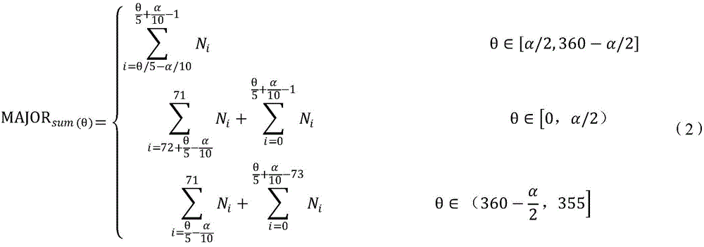
进一步,如图3所示,定义小区天线主瓣方向夹角为α(α=10*l,l=1,2,…,36,单位:度,可参考小区天线水平波瓣宽度参数设置值),并定义以α为圆心角的无限大扇形区域为小区主瓣方向覆盖区域。更进一步的,以0°线为扇形中心法线方向起点,如图4所示,将以α为圆心角的扇形区域以5°为精度顺时针旋转,使天线的主瓣方向处于不同的方向,定义扇形中心法线方向(扇形角平分线)与0°线的夹角为θ(θ=5*i,i=0,1,2,…,71,单位:度)。分别计算不同θ取值时,对应的小区主瓣方向覆盖区域内的AOA采样点数MAJORsum(θ)(即第一数量)。其中,MAJORsum(θ)可以采用以下公式(2)进行计算。Further, as shown in Figure 3, define the included angle of the main lobe direction of the cell antenna as α(α=10*l, l=1,2,...,36, unit: degree, you can refer to the setting value of the cell antenna horizontal lobe width parameter ), and define an infinite fan-shaped area with α as the central angle as the coverage area in the direction of the main lobe of the cell. Further, take the 0° line as the starting point of the normal direction of the sector center, as shown in Figure 4, rotate the sector area with α as the central angle clockwise with an accuracy of 5°, so that the main lobe directions of the antenna are in different directions. , define the angle between the normal direction of the fan center (sector angle bisector) and the 0° line as θ (θ=5*i, i=0,1,2,...,71, unit: degree). When calculating different θ values respectively, MAJOR sum(θ) (ie, the first number) of the AOA sampling points in the coverage area in the main lobe direction of the corresponding cell. Among them, MAJOR sum(θ) can be calculated by the following formula (2).

由上述公式(2)即可计算得出小区主瓣方向AOA采样点数集合RMsum:From the above formula (2), the set RM sum of the AOA sampling points in the main lobe direction of the cell can be calculated:
RMsum={MAJORsum(0),MAJORsum(5),MAJORsum(10),…,MAJORsum(350),MAJORsum(355)} (3)RM sum = {MAJORsum(0),MAJORsum(5),MAJORsum(10),...,MAJORsum(350),MAJORsum(355)} (3)
最后,分别计算不同θ取值中,对应的小区主瓣方向覆盖区域内的AOA采样点数MAJORsum(θ)与小区总AOA采样点CELLsum的比例MAJORrate(θ)(即第一比例)为Finally, calculate the ratio between the MAJOR sum(θ) of the AOA sampling points in the coverage area in the main lobe direction of the corresponding cell and the CELL sum of the total AOA sampling points in the cell, MAJOR rate(θ) (that is, the first ratio) for different θ values.

由以上公式(4)即可计算得出小区主瓣方向AOA采样点比例集合RMrate:From the above formula (4), the ratio set RM rate of AOA sampling points in the main lobe direction of the cell can be calculated:
RMrate={MAJORrate(0),MAJORrate(5),MAJORrate(10),…,MAJORrate(350),MAJORrate(355)} (5)RM rate = {MAJORrate(0),MAJORrate(5),MAJORrate(10),...,MAJORrate(350),MAJORrate(355)} (5)
S202c:根据所有连接态的用户设备的信号来源方向,利用圆周旋转分片法在所述天线的主瓣方向及旁瓣方向整体处于不同方向时,分别计算所述旁瓣方向覆盖区域内的用户设备的第二数量占所有连接态的用户设备的第二比例;S202c: According to the signal source directions of all user equipments in the connected state, using the circular rotation slicing method, when the main lobe direction and the side lobe direction of the antenna are in different directions as a whole, calculate the users in the coverage area of the side lobe direction respectively. the second number of devices accounts for a second proportion of all connected user devices;
同样的,利用“圆周旋转分片”算法计算小区旁瓣方向采样点比例,需要说明的是,天线方向图上,最大辐射波束叫做主瓣,主瓣旁边的小波束叫做旁瓣,本发明实施例综合考量主瓣方向采样点和旁瓣方向采样点比例,可以进一步准确确定用户设备最密集的区域,便于将最大辐射波束和小波束都集中在用户设备密集区域。Similarly, the "circular rotation slice" algorithm is used to calculate the proportion of sampling points in the side lobe direction of the cell. It should be noted that on the antenna pattern, the largest radiation beam is called the main lobe, and the small beam next to the main lobe is called the side lobe. For example, by comprehensively considering the ratio of sampling points in the main lobe direction and sampling points in the side lobe direction, the area with the most dense user equipment can be further accurately determined, so that the maximum radiation beam and small beam can be concentrated in the dense area of user equipment.
首先,如图2所示,仍将小区全部AOA采样点按圆周形态分布,并汇总统计全部角度区间AOA采样点之和CELLsum,作为小区AOA总采样点数,如公式(6)所示,。First, as shown in Figure 2, all AOA sampling points in the cell are still distributed in a circular shape, and the sum of the AOA sampling points in all angular intervals, CELL sum , is aggregated and counted as the total number of AOA sampling points in the cell, as shown in formula (6).

第二,如图5所示,定义小区天线“主瓣+旁瓣”夹角为β(β=10*p,p=1,2,…,36,且β≥α,单位:度,可参考小区天线水平波瓣宽度参数设置值),并定义以β为圆心角的无限大扇形区域为小区主瓣+旁瓣方向覆盖区域。Second, as shown in Figure 5, define the angle between the "main lobe + side lobe" of the cell antenna as β (β=10*p, p=1,2,...,36, and β≥α, unit: degree, can be Refer to the setting value of the horizontal lobe width parameter of the cell antenna), and define an infinite fan-shaped area with β as the central angle as the coverage area in the main lobe + side lobe direction of the cell.
第三,如6所示,以0°线为扇形中心法线方向起点,将以β为圆心角的扇形区域以5°为精度顺时针旋转,定义扇形中心法线方向与0°线的夹角为θ(θ=5*i,i=0,1,2,…,71,单位:度)。分别计算不同θ取值时,对应的小区主瓣+旁瓣方向覆盖区域的AOA采样点数COVERsum(θ),COVERsum(θ)可以采用以下公式(7)进行计算:Third, as shown in 6, take the 0° line as the starting point of the normal direction of the fan center, rotate the fan area with β as the central angle clockwise with 5° as the precision, and define the clip between the normal direction of the fan center and the 0° line The angle is θ (θ=5*i, i=0,1,2,...,71, unit: degree). When calculating different θ values, the corresponding AOA sampling points in the main lobe + side lobe direction of the cell cover COVER sum(θ) , and COVER sum(θ) can be calculated using the following formula (7):

由上述公式(7)即可计算得出小区主瓣+旁瓣方向覆盖区域AOA采样点数集合RCsum:From the above formula (7), the set RC sum of AOA sampling points in the coverage area in the main lobe + side lobe direction of the cell can be calculated:
RCsum={COVERsum(0),COVERsum(5),COVERsum(10),…,COVERsum(350),COVERsum(355)} (8)RC sum = {COVERsum(0),COVERsum(5),COVERsum(10),...,COVERsum(350),COVERsum(355)} (8)
第四,如图7所示,在不同θ取值时,旁瓣方向覆盖区域内的AOA采样点数SIDEsum(θ)(即第二数量),可以采用以下公式(9)进行计算:Fourth, as shown in Figure 7, when the value of θ is different, the number of AOA sampling points SIDE sum(θ) (that is, the second number) in the coverage area of the side lobe direction can be calculated by the following formula (9):
SIDEsum(θ)=COVERsum(θ)-MAJORsum(θ) (9)SIDE sum(θ) = COVER sum(θ) - MAJOR sum(θ) (9)
进而可以计算获得小区旁瓣方向覆盖区域内的AOA采样点数集合RSsum:Then, the set of AOA sampling points RS sum in the coverage area of the cell side lobe direction can be calculated and obtained:
RSsum={SIDEsum(0),SIDEsum(5),SIDEsum(10),…,SIDEsum(350),SIDEsum(355)} (10)RS sum = {SIDE sum(0) ,SIDE sum(5) ,SIDE sum(10) ,…,SIDE sum(350) ,SIDE sum(355) } (10)
第五,分别计算不同θ取值中,对应的小区旁瓣方向覆盖区域内的AOA采样点数与占小区总AOA采样点的比例SIDErate(θ)(即第二比例),Fifth, calculate the ratio of the number of AOA sampling points in the coverage area of the corresponding cell sidelobe direction to the ratio of the total AOA sampling points of the cell SIDE rate(θ) (ie the second ratio) for different θ values.

由以上公式(11)即可计算得出小区旁瓣方向AOA采样点比例集合:From the above formula (11), the set of ratios of AOA sampling points in the cell sidelobe direction can be calculated:
RSrate={SIDErate(0),SIDErate(5),SIDErate(10),…,SIDErate(350),SIDErate(355)} (12)RS rate = {SIDE rate(0) ,SIDE rate(5) ,SIDE rate(10) ,...,SIDE rate(350) ,SIDE rate(355) } (12)
S203c:对所述第一比例和第二比例进行加权求和计算,确定求和总体值最大时的所述天线的主瓣方向及旁瓣方向。S203c: Perform a weighted sum calculation on the first ratio and the second ratio, and determine the main lobe direction and the side lobe direction of the antenna when the summed total value is the largest.
具体的,针对旁瓣方向AOA采样点比例定义权重因子δ(δ∈[0,1]),分别计算不同θ取值时,主瓣方向AOA采样点比例(即第一比例)与旁瓣方向AOA采样点比例(即第二比例)的加权值W(θ):Specifically, a weight factor δ(δ∈[0,1]) is defined for the ratio of AOA sampling points in the side lobe direction, and the ratio of AOA sampling points in the main lobe direction (ie, the first ratio) and the side lobe direction are calculated separately for different θ values. The weighted value W(θ) of the AOA sampling point ratio (ie the second ratio):
W(θ)=MAJORrate(θ)+δ*SIDErate(θ) (13)W(θ)=MAJOR rate(θ) +δ*SIDE rate(θ) (13)
由以上公式即可计算得出小区不同主瓣+旁瓣方向覆盖区域内的AOA采样点比例加权值集合RW:From the above formula, the weighted set of AOA sampling point proportions RW in the coverage area of different main lobe + side lobe directions of the cell can be calculated:
RW={W(0),W(5),W(10),…,W(350),W(355)} (14)RW={W(0),W(5),W(10),...,W(350),W(355)} (14)
通过遍历集合RW中的所有元素,取集合中最大的一个或多个W(θm),需要说明的是,最大的W(θm)表示θ值取θm时,主瓣及旁瓣方向整体覆盖区域内的用户设备数量最多,为用户设备集中区域,将相应的θ取值作为天线方向调整角度,即确定了天线的主瓣方向及旁瓣方向,将最大辐射波束和旁边的小波束都集中在用户设备集中区域。By traversing all elements in the set RW, take the largest one or more W(θ m ) in the set, it should be noted that the largest W(θ m ) indicates that when the θ value is θ m , the direction of the main lobe and side lobe The number of user equipments in the overall coverage area is the largest, which is the concentrated area of user equipment. The corresponding θ value is used as the antenna direction adjustment angle, that is, the main lobe direction and side lobe direction of the antenna are determined. All are concentrated in the user equipment concentrated area.
在上述实施例的基础上,步骤S2根据所述所有连接态的用户设备的信号来源方向,确定所述用户设备的集中区域的方向,还包括:On the basis of the above embodiment, step S2 determines the direction of the concentrated area of the user equipment according to the signal source directions of all the user equipments in the connected state, and further includes:
若求和总体值最大时的所述天线的主瓣方向及旁瓣方向存在多个;则选择第一比例最大时的所述天线的主瓣方向及旁瓣方向。If there are multiple main lobe directions and side lobe directions of the antenna when the summed total value is the largest; then select the main lobe direction and the side lobe direction of the antenna when the first ratio is the largest.
具体的,首先,遍历集合RW中全部元素,取集合中最大的一个或多个W(θm),将相应θ取值纳入最优天线方向调整角度集合A1,若集合A1内仅存在1个元素θm,则最优天线方向调整角度为θm。Specifically, first, traverse all the elements in the set RW, take the largest one or more W(θ m ) in the set, and incorporate the corresponding θ value into the optimal antenna direction adjustment angle set A1, if there is only one in the set A1 element θ m , the optimal antenna direction adjustment angle is θ m .
第二,若得到的集合A1中存在2个或以上元素θm1、θm2……θmn,则对比
第三,若得到的集合A2中仍存在2个或以上元素,则最优天线方向调整角度θm为集合A2中最小的θ取值。当θ值取θm时,主瓣及旁瓣方向整体覆盖区域内的用户设备数量最多,为用户设备集中区域,将相应的θm取值作为天线方向调整角度,即最终确定了天线的主瓣方向及旁瓣方向,将最大辐射波束和旁边的小波束都集中在用户设备集中区域。Third, if there are still two or more elements in the obtained set A2, the optimal antenna direction adjustment angle θ m is the smallest θ value in the set A2. When the value of θ is θ m , the number of user equipments in the overall coverage area of the main lobe and side lobe directions is the largest, which is the area where user equipment is concentrated. The lobe direction and the side lobe direction concentrate the maximum radiation beam and the small beams next to it in the concentrated area of the user equipment.
另一方面,如图8所示,本发明实施例还提供的一种天线方向调整装置,该装置可以采用上述实施例所述的天线方向调整方法,该装置可以为上述实施例所述的基站,该装置包括:依次连接的角度采集模块81、区域确定模块82和天线调整模块83;On the other hand, as shown in FIG. 8 , an embodiment of the present invention further provides an antenna direction adjustment apparatus, which may adopt the antenna direction adjustment method described in the foregoing embodiment, and the apparatus may be the base station described in the foregoing embodiment. , the device includes: an
其中,角度采集模块81用于采集小区内所有连接态的用户设备的信号来源方向;Wherein, the
区域确定模块82用于根据所述所有连接态的用户设备的信号来源方向,确定所述用户设备的集中区域的方向;The
天线调整模块83用于根据所述用户设备的集中区域的方向,调整所述天线的方向角,以使所述天线的电磁波能量集中在用户设备的集中区域。The
具体的,角度采集模块81采集小区内所有连接态的用户设备的信号来源方向;区域确定模块82根据所述所有连接态的用户设备的信号来源方向,确定所述用户设备的集中区域的方向;天线调整模块83根据所述用户设备的集中区域的方向,调整所述天线的方向角,以使所述天线的电磁波能量集中在用户设备的集中区域。Specifically, the
本发明实施例提供的天线方向调整装置,通过采集用户设备的信号来源方向,确定小区内用户分布最密集的区域,以此指导小区内天线的方向调整,本发明实施例提供的技术方案,能够保证将电磁波能量集中于小区内用户集中的区域,能够最大化小区覆盖和流量价值。同时解决了现有天线调整方案中以道路为主,不考虑现网实际用户分布的问题,也解决了现有调整方案多依据工参和经验,效率不高精准度不高的问题。The apparatus for adjusting the antenna direction provided by the embodiment of the present invention determines the area where users are most densely distributed in the cell by collecting the signal source direction of the user equipment, so as to guide the direction adjustment of the antenna in the cell. The technical solution provided by the embodiment of the present invention can Ensure that the electromagnetic wave energy is concentrated in the area where users are concentrated in the cell, which can maximize cell coverage and traffic value. At the same time, it solves the problem that the existing antenna adjustment scheme mainly focuses on roads and does not consider the actual user distribution of the existing network, and also solves the problem that the existing adjustment scheme is based on labor parameters and experience, and the efficiency is not high and the accuracy is not high.
可选的,所述区域确定模块82包括:Optionally, the
平均角度计算单元,用于根据所有连接态的用户设备的信号来源方向,确定信号来源方向的平均值;The average angle calculation unit is used to determine the average value of the signal source directions according to the signal source directions of all connected user equipments;
集中方向确定单元,用于根据所述信号来源方向的平均值,确定用户设备的集中区域的方向。The concentration direction determining unit is configured to determine the direction of the concentration area of the user equipment according to the average value of the signal source directions.
可选的,所述区域确定模块82包括:Optionally, the
区间用户确定单元,用于根据所有连接态的用户设备的信号来源方向,确定不同角度区间的用户设备数量;an interval user determination unit, configured to determine the number of user equipments in different angle intervals according to the signal source directions of all connected user equipments;
角度区间确定单元,用于根据所述不同角度区间的用户设备数量,确定用户设备数量最多的角度区间;an angle interval determination unit, configured to determine the angle interval with the largest number of user equipments according to the number of user equipments in the different angle intervals;
集中区域确定单元,用于根据所述用户设备数量最多的角度区间,确定所述用户设备的集中区域的方向。A concentrated area determination unit, configured to determine the direction of the concentrated area of the user equipment according to the angle interval with the largest number of the user equipment.
可选的,所述区域确定模块82包括:Optionally, the
第一比例确定单元,用于根据所有连接态的用户设备的信号来源方向,利用圆周旋转分片法在所述天线的主瓣方向处于不同方向时,分别计算所述主瓣方向覆盖区域内的用户设备的第一数量占所有连接态的用户设备的第一比例;The first ratio determination unit is used for calculating the signal source directions of the user equipments in all connected states, using the circular rotation slicing method, when the main lobe directions of the antenna are in different directions, respectively calculating the coverage area of the main lobe direction. The first number of user equipment accounts for the first proportion of all connected user equipments;
第二比例确定单元,用于根据所有连接态的用户设备的信号来源方向,利用圆周旋转分片法在所述天线的主瓣方向及旁瓣方向整体处于不同方向时,分别计算所述旁瓣方向覆盖区域内的用户设备的第二数量占所有连接态的用户设备的第二比例;The second ratio determination unit is configured to calculate the side lobes respectively when the main lobe direction and the side lobe directions of the antenna are in different directions according to the signal source directions of the user equipments in all connected states by using the circular rotation slicing method. The second number of user equipments in the direction coverage area accounts for a second proportion of all connected user equipments;
加权计算单元,用于对所述第一比例和第二比例进行加权求和计算,确定求和总体值最大时的所述天线的主瓣方向及旁瓣方向。The weighting calculation unit is configured to perform weighted sum calculation on the first ratio and the second ratio, and determine the main lobe direction and the side lobe direction of the antenna when the summed total value is the largest.
可选的,所述加权计算单元还用于在求和总体值最大时的所述天线的主瓣方向及旁瓣方向存在多个时;选择第一比例最大时的所述天线的主瓣方向及旁瓣方向。Optionally, the weighting calculation unit is also used to select the main lobe direction of the antenna when the first ratio is the largest when there are multiple main lobe directions and side lobe directions of the antenna when the summed overall value is the largest; and side lobe direction.
对于与方法对应的天线方向调整装置实施例而言,由于其与方法实施例基本相似,达到的技术效果也与方法实施例起到的效果相同,所以描述的比较简单,相关之处参见方法实施例的部分说明即可。For the embodiment of the antenna direction adjustment device corresponding to the method, since it is basically similar to the method embodiment, and the technical effect achieved is also the same as the effect achieved by the method embodiment, the description is relatively simple, and the relevant details refer to the method implementation Part of the example can be explained.
再一方面,如图9所示,本发明实施例还提供了一种电子设备,该电子设备可以是上述实施例所述的装置,该电子设备包括至少一个处理器(processor)91、通信接口(Communications Interface)92、至少一个存储器(memory)93和总线94,其中,处理器91,通信接口92,存储器93通过总线94完成相互间的通信。通信接口92可以用于该电子设备与用户设备之间的信息传输。处理器91可以调用存储器93中的逻辑指令,以执行上述实施例所述的方法,例如包括:采集小区内所有连接态的用户设备的信号来源方向;根据所述所有连接态的用户设备的信号来源方向,确定所述用户设备的集中区域的方向;根据所述用户设备的集中区域的方向,调整所述天线的方向,以使所述天线的电磁波能量集中在用户设备的集中区域。On the other hand, as shown in FIG. 9 , an embodiment of the present invention further provides an electronic device. The electronic device may be the device described in the above-mentioned embodiment, and the electronic device includes at least one processor (processor) 91, a communication interface (Communications Interface) 92 , at least one
此外,上述的存储器93中的逻辑指令可以通过软件功能单元的形式实现并作为独立的产品销售或使用时,可以存储在一个计算机可读取存储介质中。基于这样的理解,本发明的技术方案本质上或者说对现有技术做出贡献的部分或者该技术方案的部分可以以软件产品的形式体现出来,该计算机软件产品存储在一个存储介质中,包括若干指令用以使得一台计算机设备(可以是个人计算机,服务器,或者网络设备等)执行本发明各个实施例所述方法的全部或部分步骤。而前述的存储介质包括:U盘、移动硬盘、只读存储器(ROM,Read-Only Memory)、随机存取存储器(RAM,Random Access Memory)、磁碟或者光盘等各种可以存储程序代码的介质。In addition, the above-mentioned logic instructions in the
本发明实施例提供了一种计算机程序产品,所述计算机程序产品包括存储在非暂态计算机可读存储介质上的计算机程序,所述计算机程序包括程序指令,当所述程序指令被计算机执行时,计算机能够执行上述各方法实施例所提供的方法,例如包括:采集小区内所有连接态的用户设备的信号来源方向;根据所述所有连接态的用户设备的信号来源方向,确定所述用户设备的集中区域的方向;根据所述用户设备的集中区域的方向,调整所述天线的方向,以使所述天线的电磁波能量集中在用户设备的集中区域。An embodiment of the present invention provides a computer program product, the computer program product includes a computer program stored on a non-transitory computer-readable storage medium, the computer program includes program instructions, and when the program instructions are executed by a computer , the computer can execute the methods provided by the above method embodiments, for example, including: collecting signal source directions of all connected user equipments in the cell; determining the user equipment according to the signal source directions of all connected user equipments The direction of the concentrated area of the user equipment; adjust the direction of the antenna according to the direction of the concentrated area of the user equipment, so that the electromagnetic wave energy of the antenna is concentrated in the concentrated area of the user equipment.
本发明实施例提供了一种非暂态计算机可读存储介质,所述非暂态计算机可读存储介质存储计算机指令,所述计算机指令使所述计算机执行上述各方法实施例所提供的方法,例如包括:采集小区内所有连接态的用户设备的信号来源方向;根据所述所有连接态的用户设备的信号来源方向,确定所述用户设备的集中区域的方向;根据所述用户设备的集中区域的方向,调整所述天线的方向,以使所述天线的电磁波能量集中在用户设备的集中区域。An embodiment of the present invention provides a non-transitory computer-readable storage medium, where the non-transitory computer-readable storage medium stores computer instructions, and the computer instructions cause the computer to execute the methods provided by the foregoing method embodiments, For example, it includes: collecting the signal source directions of all connected user equipments in the cell; determining the direction of the concentrated area of the user equipment according to the signal source directions of all connected user equipments; according to the concentrated area of the user equipment The direction of the antenna is adjusted, so that the electromagnetic wave energy of the antenna is concentrated in the concentrated area of the user equipment.
以上所描述的装置实施例仅仅是示意性的,其中所述作为分离部件说明的单元可以是或者也可以不是物理上分开的,作为单元显示的部件可以是或者也可以不是物理单元,即可以位于一个地方,或者也可以分布到多个网络单元上。可以根据实际的需要选择其中的部分或者全部模块来实现本实施例方案的目的。本领域普通技术人员在不付出创造性的劳动的情况下,即可以理解并实施。The device embodiments described above are only illustrative, wherein the units described as separate components may or may not be physically separated, and the components shown as units may or may not be physical units, that is, they may be located in One place, or it can be distributed over multiple network elements. Some or all of the modules may be selected according to actual needs to achieve the purpose of the solution in this embodiment. Those of ordinary skill in the art can understand and implement it without creative effort.
通过以上的实施方式的描述,本领域的技术人员可以清楚地了解到各实施方式可借助软件加必需的通用硬件平台的方式来实现,当然也可以通过硬件。基于这样的理解,上述技术方案本质上或者说对现有技术做出贡献的部分可以以软件产品的形式体现出来,该计算机软件产品可以存储在计算机可读存储介质中,如ROM/RAM、磁碟、光盘等,包括若干指令用以使得一台计算机设备(可以是个人计算机,服务器,或者网络设备等)执行各个实施例或者实施例的某些部分所述的方法。From the description of the above embodiments, those skilled in the art can clearly understand that each embodiment can be implemented by means of software plus a necessary general hardware platform, and certainly can also be implemented by hardware. Based on this understanding, the above-mentioned technical solutions can be embodied in the form of software products in essence or the parts that make contributions to the prior art, and the computer software products can be stored in computer-readable storage media, such as ROM/RAM, magnetic A disc, an optical disc, etc., includes several instructions for causing a computer device (which may be a personal computer, a server, or a network device, etc.) to perform the methods described in various embodiments or some parts of the embodiments.
最后应说明的是:以上实施例仅用以说明本发明的技术方案,而非对其限制;尽管参照前述实施例对本发明进行了详细的说明,本领域的普通技术人员应当理解:其依然可以对前述各实施例所记载的技术方案进行修改,或者对其中部分技术特征进行等同替换;而这些修改或者替换,并不使相应技术方案的本质脱离本发明各实施例技术方案的精神和范围。Finally, it should be noted that the above embodiments are only used to illustrate the technical solutions of the present invention, but not to limit them; although the present invention has been described in detail with reference to the foregoing embodiments, those of ordinary skill in the art should understand that it can still be The technical solutions described in the foregoing embodiments are modified, or some technical features thereof are equivalently replaced; and these modifications or replacements do not make the essence of the corresponding technical solutions deviate from the spirit and scope of the technical solutions of the embodiments of the present invention.
Claims (4)


Priority Applications (1)
| Application Number | Priority Date | Filing Date | Title |
|---|---|---|---|
| CN201611138756.8A CN108615978B (en) | 2016-12-12 | 2016-12-12 | Method and device for adjusting antenna direction |
Applications Claiming Priority (1)
| Application Number | Priority Date | Filing Date | Title |
|---|---|---|---|
| CN201611138756.8A CN108615978B (en) | 2016-12-12 | 2016-12-12 | Method and device for adjusting antenna direction |
Publications (2)
| Publication Number | Publication Date |
|---|---|
| CN108615978A CN108615978A (en) | 2018-10-02 |
| CN108615978B true CN108615978B (en) | 2020-09-25 |
Family
ID=63643688
Family Applications (1)
| Application Number | Title | Priority Date | Filing Date |
|---|---|---|---|
| CN201611138756.8A Active CN108615978B (en) | 2016-12-12 | 2016-12-12 | Method and device for adjusting antenna direction |
Country Status (1)
| Country | Link |
|---|---|
| CN (1) | CN108615978B (en) |
Families Citing this family (5)
| Publication number | Priority date | Publication date | Assignee | Title |
|---|---|---|---|---|
| CN111698012B (en) * | 2019-03-11 | 2021-08-27 | 大唐移动通信设备有限公司 | Beam utilization rate optimization method and device |
| CN110446248A (en) * | 2019-06-28 | 2019-11-12 | 维沃移动通信有限公司 | A kind of antenna gain adjustment method and terminal equipment |
| CN110474167B (en) * | 2019-08-26 | 2021-07-16 | 联想(北京)有限公司 | Electromagnetic wave control method and device |
| WO2022226966A1 (en) * | 2021-04-30 | 2022-11-03 | 京东方科技集团股份有限公司 | Recommendation information sending method and positioning service device |
| CN114390541B (en) * | 2021-12-29 | 2025-02-11 | 中国电信股份有限公司 | Antenna adjustment method, device, system, antenna and medium |
Citations (9)
| Publication number | Priority date | Publication date | Assignee | Title |
|---|---|---|---|---|
| EP0895701A1 (en) * | 1996-05-27 | 1999-02-10 | Nokia Telecommunications Oy | Method for optimising coverage by reshaping antenna pattern |
| WO2009008789A1 (en) * | 2007-07-06 | 2009-01-15 | Telefonaktiebolaget L M Ericsson (Publ) | Method and apparatus for improving the performance of a mobile radio communications system by adjusting antenna patterns |
| CN102340785A (en) * | 2010-07-20 | 2012-02-01 | 中兴通讯股份有限公司 | Antenna adjustment method and base station |
| CN102564388A (en) * | 2012-01-17 | 2012-07-11 | 大唐移动通信设备有限公司 | Method and device for determining horizontal direction angles of antennae of base station |
| CN103178882A (en) * | 2011-12-23 | 2013-06-26 | 中国移动通信集团公司 | A 3D MIMO downtilt adjustment method, device and base station |
| CN103428726A (en) * | 2012-05-15 | 2013-12-04 | 中国移动通信集团黑龙江有限公司 | Antenna angle optimization method and system |
| CN103596190A (en) * | 2012-08-17 | 2014-02-19 | 中国移动通信集团设计院有限公司 | Method and apparatus for determining cell coverage concentration |
| WO2015110166A1 (en) * | 2014-01-24 | 2015-07-30 | Nokia Solutions And Networks Oy | Determining an adjustment of a tilt angle for an antenna serving a vertically sectorized cell of a radio network |
| CN105165053A (en) * | 2013-05-16 | 2015-12-16 | 英特尔Ip公司 | Generation and use of user equipment location distributions in wireless communication networks |
Family Cites Families (1)
| Publication number | Priority date | Publication date | Assignee | Title |
|---|---|---|---|---|
| ES2382794B1 (en) * | 2009-09-22 | 2013-05-08 | Vodafone España, S.A.U. | METHOD FOR DYNAMICALLY ESTABLISHING THE RADIATION PATTERN OF AN ANTENNA BASED ON USER EQUIPMENT POSITIONING INFORMATION |
-
2016
- 2016-12-12 CN CN201611138756.8A patent/CN108615978B/en active Active
Patent Citations (9)
| Publication number | Priority date | Publication date | Assignee | Title |
|---|---|---|---|---|
| EP0895701A1 (en) * | 1996-05-27 | 1999-02-10 | Nokia Telecommunications Oy | Method for optimising coverage by reshaping antenna pattern |
| WO2009008789A1 (en) * | 2007-07-06 | 2009-01-15 | Telefonaktiebolaget L M Ericsson (Publ) | Method and apparatus for improving the performance of a mobile radio communications system by adjusting antenna patterns |
| CN102340785A (en) * | 2010-07-20 | 2012-02-01 | 中兴通讯股份有限公司 | Antenna adjustment method and base station |
| CN103178882A (en) * | 2011-12-23 | 2013-06-26 | 中国移动通信集团公司 | A 3D MIMO downtilt adjustment method, device and base station |
| CN102564388A (en) * | 2012-01-17 | 2012-07-11 | 大唐移动通信设备有限公司 | Method and device for determining horizontal direction angles of antennae of base station |
| CN103428726A (en) * | 2012-05-15 | 2013-12-04 | 中国移动通信集团黑龙江有限公司 | Antenna angle optimization method and system |
| CN103596190A (en) * | 2012-08-17 | 2014-02-19 | 中国移动通信集团设计院有限公司 | Method and apparatus for determining cell coverage concentration |
| CN105165053A (en) * | 2013-05-16 | 2015-12-16 | 英特尔Ip公司 | Generation and use of user equipment location distributions in wireless communication networks |
| WO2015110166A1 (en) * | 2014-01-24 | 2015-07-30 | Nokia Solutions And Networks Oy | Determining an adjustment of a tilt angle for an antenna serving a vertically sectorized cell of a radio network |
Non-Patent Citations (1)
| Title |
|---|
| "GSM网络高层楼宇室内覆盖解决方案浅析";邓金华;《硅谷》;20101231;全文 * |
Also Published As
| Publication number | Publication date |
|---|---|
| CN108615978A (en) | 2018-10-02 |
Similar Documents
| Publication | Publication Date | Title |
|---|---|---|
| CN108615978B (en) | Method and device for adjusting antenna direction | |
| EP3890361B1 (en) | Cell longitude and latitude prediction method and device, server, base station, and storage medium | |
| CN109963287B (en) | Antenna direction angle optimization method, device, equipment and medium | |
| CN113765550A (en) | Communication method and related device | |
| US8565106B2 (en) | Iterative localization techniques | |
| CN109495899A (en) | Parameter optimization method, device, electronic equipment and the storage medium of antenna | |
| CN113840224B (en) | Communication method and device | |
| US20140003365A1 (en) | System for continuously improving the performance of wireless networks with mobile users | |
| CN100512516C (en) | Method for positioning moving platform | |
| CN113965942B (en) | A network configuration method and device | |
| CN109490826B (en) | A method of ranging and position positioning based on radio wave field strength RSSI | |
| WO2013136128A1 (en) | Generating radio channel models parameter values | |
| Yan et al. | Improved hop‐based localisation algorithm for irregular networks | |
| CN104735707B (en) | A kind of failure antenna positioning method, device and electronic equipment | |
| CN108024327B (en) | User positioning method and device | |
| Brida et al. | An experimental evaluation of AGA algorithm for RSS positioning in GSM networks | |
| WO2017020273A1 (en) | Method and device for positioning and method of generating a positioning database in multicarrier network | |
| CN109219976B (en) | A method and apparatus for generating measurement results | |
| CN107182066B (en) | Method and device for checking whole-network station work parameters based on periodic measurement data | |
| Izydorczyk et al. | Angular distribution of cellular signals for UAVs in urban and rural scenarios | |
| CN106796277B (en) | Location Adjustment in Mobile Communication Networks | |
| CN116347495B (en) | Method, device, equipment and storage medium for calculating antenna azimuth | |
| CN112020006A (en) | Antenna adjustment method, device, equipment and computer storage medium | |
| CN115696380B (en) | Method, device, equipment and storage medium for determining 5G antenna beam | |
| CN114339776B (en) | Antenna weight tuning method, device, device and computer-readable storage medium |
Legal Events
| Date | Code | Title | Description |
|---|---|---|---|
| PB01 | Publication | ||
| PB01 | Publication | ||
| SE01 | Entry into force of request for substantive examination | ||
| SE01 | Entry into force of request for substantive examination | ||
| GR01 | Patent grant | ||
| GR01 | Patent grant |