CN108495113B - Control method and device for binocular vision system - Google Patents
Control method and device for binocular vision system Download PDFInfo
- Publication number
- CN108495113B CN108495113B CN201810259316.0A CN201810259316A CN108495113B CN 108495113 B CN108495113 B CN 108495113B CN 201810259316 A CN201810259316 A CN 201810259316A CN 108495113 B CN108495113 B CN 108495113B
- Authority
- CN
- China
- Prior art keywords
- sensor
- light source
- light
- image
- target object
- Prior art date
- Legal status (The legal status is an assumption and is not a legal conclusion. Google has not performed a legal analysis and makes no representation as to the accuracy of the status listed.)
- Active
Links
- 238000000034 method Methods 0.000 title claims abstract description 69
- 230000004044 response Effects 0.000 claims abstract description 45
- 238000004590 computer program Methods 0.000 claims description 12
- 238000000605 extraction Methods 0.000 claims description 8
- 238000010586 diagram Methods 0.000 description 11
- 230000006870 function Effects 0.000 description 7
- 238000004891 communication Methods 0.000 description 6
- 239000000284 extract Substances 0.000 description 6
- 230000008569 process Effects 0.000 description 6
- 238000001514 detection method Methods 0.000 description 4
- 230000003287 optical effect Effects 0.000 description 4
- 230000000694 effects Effects 0.000 description 3
- 239000004065 semiconductor Substances 0.000 description 3
- 238000005516 engineering process Methods 0.000 description 2
- 239000000835 fiber Substances 0.000 description 2
- 230000000644 propagated effect Effects 0.000 description 2
- 230000000295 complement effect Effects 0.000 description 1
- 238000005259 measurement Methods 0.000 description 1
- 229910044991 metal oxide Inorganic materials 0.000 description 1
- 150000004706 metal oxides Chemical class 0.000 description 1
- 239000013307 optical fiber Substances 0.000 description 1
- 238000005457 optimization Methods 0.000 description 1
Images


Landscapes
- Length Measuring Devices By Optical Means (AREA)
Abstract
The embodiment of the application discloses a control method and device for a binocular vision system. One embodiment of the method comprises: controlling a light source to emit structured light toward a target object to form a preset pattern on a surface of the target object; acquiring a first image acquired by a first sensor on a target object and a second image acquired by a second sensor on the target object; extracting feature points from the first image and the second image; and in response to determining that the number of the feature points is greater than or equal to the number threshold, performing stereo matching on the first image and the second image based on the feature points, and generating depth information of the target object. This embodiment improves the accuracy of the depth image.
Description
Technical Field
The embodiment of the application relates to the technical field of computers, in particular to a control method and device for a binocular vision system.
Background
The depth camera can acquire depth information of objects in a scene, and is widely applied to the fields of safety certification, unmanned aerial vehicle obstacle avoidance, three-dimensional reconstruction and the like. The binocular stereo vision technology is an important technical means for a depth camera to acquire depth information of objects in a scene.
In a binocular vision camera, two cameras shoot the same scene from different angles (i.e., different viewpoints), and two digital images of the scene containing parallax information are obtained. The coordinate positions of the same point in the scene in the two images are determined through stereo matching, and the spatial three-dimensional coordinates of the point can be calculated by utilizing a triangular distance measurement principle according to the relative positions of the two cameras.
Disclosure of Invention
The embodiment of the application provides a control method and device for a binocular vision system.
In a first aspect, an embodiment of the present application provides a control method for a binocular vision system, where the binocular vision system includes a light source, a first sensor and a second sensor, the method includes: controlling a light source to emit structured light toward a target object to form a preset pattern on a surface of the target object; acquiring a first image acquired by a first sensor on a target object and a second image acquired by a second sensor on the target object; extracting feature points from the first image and the second image; and in response to determining that the number of the feature points is greater than or equal to the number threshold, performing stereo matching on the first image and the second image based on the feature points, and generating depth information of the target object.
In some embodiments, the method further comprises: in response to determining that the number of the feature points is less than the number threshold, obtaining intensities of light sensed by the first sensor and/or the second sensor respectively under the conditions that the light source emits structured light and the light source does not emit structured light; in response to determining that a ratio of the intensity of light sensed under the condition that the light source emits structured light to the intensity of light sensed under the condition that the light source does not emit structured light is greater than or equal to a preset ratio, determining a difference between a time instant when the light source emits structured light and a time instant when the first sensor and/or the second sensor senses reflected light of the structured light after the light source emits structured light; based on the difference, depth information of the target object is generated.
In some embodiments, the method further comprises: in response to determining that the number of the feature points is less than the number threshold, obtaining intensities of light sensed by the first sensor and/or the second sensor respectively under the conditions that the light source emits structured light and the light source does not emit structured light; in response to determining that a ratio of the intensity of light sensed under the condition that the light source emits structured light to the intensity of light sensed under the condition that the light source does not emit structured light is greater than or equal to a preset ratio, determining a difference value between a phase of the structured light emitted by the light source and a phase of reflected light of the structured light sensed by the first sensor and/or the second sensor after the light source emits the structured light; based on the difference, depth information of the target object is generated.
In some embodiments, the first sensor and the second sensor are symmetrically disposed to each other on both sides of the light source.
In some embodiments, the predetermined pattern is a speckle pattern having a predetermined resolution.
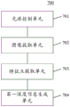
In a second aspect, an embodiment of the present application provides a control apparatus for a binocular vision system, the binocular vision system including a light source, a first sensor and a second sensor, the apparatus including: a light source control unit configured to control a light source to emit structured light toward a target object to form a preset pattern on a surface of the target object; the image acquisition unit is configured to acquire a first image acquired by the first sensor on the target object and a second image acquired by the second sensor on the target object; a feature point extraction unit configured to extract feature points from the first image and the second image; and a first depth information generating unit configured to generate depth information of the target object based on stereo matching of the first image and the second image by the feature point in response to determination that the number of the feature points is equal to or greater than the number threshold.
In some embodiments, the apparatus further comprises: the light intensity acquisition unit is configured to respond to the fact that the number of the characteristic points is smaller than the number threshold value, and acquire the intensity of light sensed by the first sensor and/or the second sensor under the condition that the light source emits structured light and the light source does not emit structured light; a time determining unit configured to determine a difference between a time at which the light source emits the structured light and a time at which the first sensor and/or the second sensor senses reflected light of the structured light after the light source emits the structured light, in response to determining that a ratio of the intensity of light sensed under the condition that the light source emits the structured light to the intensity of light sensed under the condition that the light source does not emit the structured light is greater than or equal to a preset ratio; a second depth information generating unit configured to generate depth information of the target object based on the difference value.
In some embodiments, the apparatus further comprises: the light intensity acquisition unit is configured to respond to the fact that the number of the characteristic points is smaller than the number threshold value, and acquire the intensity of light sensed by the first sensor and/or the second sensor under the condition that the light source emits structured light and the light source does not emit structured light; a phase determination unit configured to determine a difference between a phase of the structured light emitted by the light source and a phase of reflected light of the structured light sensed by the first sensor and/or the second sensor after the light source emits the structured light, in response to determining that a ratio of an intensity of light sensed under a condition that the light source emits the structured light to an intensity of light sensed under a condition that the light source does not emit the structured light is greater than or equal to a preset ratio; a second depth information generating unit configured to generate depth information of the target object based on the difference value.
In some embodiments, the first sensor and the second sensor are symmetrically disposed to each other on both sides of the light source.
In some embodiments, the predetermined pattern is a speckle pattern having a predetermined resolution.
In a third aspect, an embodiment of the present application provides an electronic device, including: a controller comprising one or more processors; a light source; a first sensor; a second sensor; storage means for storing one or more programs; when the one or more programs are executed by the controller, the controller is caused to implement the method as described in any implementation of the first aspect.
In a fourth aspect, the present application provides a computer-readable medium, on which a computer program is stored, which, when executed by a processor, implements the method as described in any implementation manner of the first aspect.
According to the control method and device for the binocular vision system, the structured light pattern is projected to the target object through the control light source, then the first image acquired by the first sensor to the target object and the second image acquired by the second sensor to the target object are obtained, the feature points are extracted from the first image and the second image, and finally the first image and the second image are subjected to stereo matching in response to the fact that the number of the feature points is larger than the number threshold value, the depth image is generated, and therefore accuracy of the depth image is improved.
Drawings
Other features, objects and advantages of the present application will become more apparent upon reading of the following detailed description of non-limiting embodiments thereof, made with reference to the accompanying drawings in which:
FIG. 1 is an exemplary system architecture diagram in which the present application may be applied;
fig. 2 is a flowchart of one embodiment of a control method for a binocular vision system according to the present application;
FIG. 3 is a schematic diagram illustrating one implementation of the embodiment shown in FIG. 2;
fig. 4 is a schematic diagram of an application scenario of a control method for a binocular vision system according to the present application;
fig. 5 is a flowchart of another embodiment of a control method for a binocular vision system according to the present application;
fig. 6 is a flowchart of yet another embodiment of a control method for a binocular vision system according to the present application;
fig. 7 is a schematic structural view of an embodiment of a control apparatus for a binocular vision system according to the present application;
FIG. 8 is a block diagram of a computer system suitable for use in implementing the electronic device of an embodiment of the present application.
Detailed Description
The present application will be described in further detail with reference to the following drawings and examples. It is to be understood that the specific embodiments described herein are merely illustrative of the relevant invention and not restrictive of the invention. It should be noted that, for convenience of description, only the portions related to the related invention are shown in the drawings.
It should be noted that the embodiments and features of the embodiments in the present application may be combined with each other without conflict. The present application will be described in detail below with reference to the embodiments with reference to the attached drawings.
Fig. 1 illustrates an exemplary system architecture 100 in which the present application may be applied.
As shown in fig. 1, the system architecture 100 may include a binocular vision system 101, a network 102, and a controller 103. Network 102 is used to provide a medium for a communication link between binocular vision system 101 and controller 103. Network 102 may include various connection types, such as wired, wireless communication links, or fiber optic cables, to name a few.
The binocular vision system 101 may interact with the controller 103 through the network 102 to receive or transmit messages. The binocular vision system 101 may be equipped with a light source 104, a first sensor 105, and a second sensor 106. Wherein the light source 104 is used for emitting structured light to the target object, and the first sensor 105 and the second sensor 106 are used for sensing echo light reflected by the target object and for acquiring an image of the target object.
The controller 103 may or may not be mounted on the binocular vision system 101. The controller 103 is used for various controls of the binocular vision system 101, for example, the controller 103 may control the light source 104 to emit structured light to the target object, the controller 103 may also control the first sensor 105 and/or the second sensor 106 to sense echo light reflected by the target object, or control the first sensor 105 and the second sensor 106 to perform image acquisition on the target object.
It should be noted that the control method for the binocular vision system provided in the embodiment of the present application is generally executed by the controller 103, and accordingly, the control device for the binocular vision system is generally provided in the controller 103.
The controller may be hardware or software. When the controller is hardware, it may be implemented as a distributed device cluster formed by multiple devices, or may be implemented as a single device. When the controller is software, it may be implemented as a plurality of software or software modules (for example, to provide distributed services), or may be implemented as a single software or software module, and is not particularly limited herein.
It should be understood that the number of binocular vision systems, networks, controllers, light sources, first sensors, and second sensors in fig. 1 are merely illustrative. There may be any number of binocular vision systems, networks, controllers, light sources, first sensors, and second sensors, as desired for implementation.
With continued reference to fig. 2, a flow 200 of one embodiment of a control method for a binocular vision system according to the present application is shown. The flow 200 of the control method for the binocular vision system includes the following steps:
In this embodiment, a binocular vision system (e.g., the binocular vision system of fig. 1) may include a light source, a first sensor, and a second sensor. An executive body (e.g., a controller shown in fig. 1) of the control method for the binocular vision system may control the light source such that the light source emits structured light toward the target object to form a preset pattern (e.g., a dot pattern, a line pattern, a plane pattern, etc.) on the surface of the target object.
Here, the control of the light source may be realized by the execution body sending a light emission instruction (for example, an instruction of "emitting the structured light to the target object") to the binocular vision system, and may also be realized in other suitable manners, for example, by adding a light shielding device between the light source and the target object to control whether the structured light is emitted to the target object, which is not specifically limited in the present application.
In some optional implementations of this embodiment, the light source may be a laser light source. Since the laser light source has good directivity, a clear structured light pattern can be formed on the surface of the target object. The laser light source may be a monochromatic light source, for example, a red laser light source, a green laser light source, a blue laser light source, or the like.
In some optional implementations of the present embodiment, the predetermined pattern is a speckle pattern with a predetermined resolution. The preset resolution may be QVGA (i.e., 320 × 240), QQVGA (i.e., 160 × 120), and the like. For example, as shown in fig. 3, which shows a schematic diagram of one implementation of the embodiment shown in fig. 2. As can be seen from fig. 3, by projecting the preset pattern 302 with a preset resolution (e.g., 320 × 240) onto the surface of the target object 301, more detailed depth information can be obtained, so that a high-resolution depth image can be produced, and the accuracy of the depth image is improved.
In the present embodiment, an executing body (e.g., a controller shown in fig. 1) of the control method for the binocular vision system may control the first sensor and the second sensor to perform image capturing of the target object, and then acquire the first image captured by the first sensor and the second image captured by the second sensor. The first sensor and the second sensor may be image sensors (also referred to as photosensitive elements), and may include, for example, a CCD (Charge Coupled Device), a CMOS (Complementary Metal-Oxide Semiconductor), and the like.
Here, the first image and the second image may be grayscale images or RGB color images, and the present application is not limited to this.
In the present embodiment, an execution subject (e.g., a controller shown in fig. 1) of the control method for the binocular vision system may extract feature points from the first image and the second image described above. The feature points are also called interest points and key points, and are some points which are highlighted in the image and have representative significance, and image recognition, stereo matching, 3D reconstruction and the like can be performed through the points. The feature points may be extracted in various ways, for example, by using a speedup Robust Features (Robust local feature point detection and description algorithm) operator to extract the feature points in the first image and the second image.
And step 204, in response to the fact that the number of the characteristic points is larger than or equal to the number threshold, performing stereo matching on the first image and the second image based on the characteristic points, and generating depth information of the target object.
In the present embodiment, the execution subject (e.g., the controller shown in fig. 1) of the control method for the binocular vision system may first determine whether the number of feature points extracted in step 203 is less than a number threshold. The quantity threshold is a feature point quantity value preset according to the requirement of an actual application scene and is used for representing the reliability of stereo matching of the first image and the second image. For example, if the number of the extracted feature points is greater than or equal to the number threshold, it indicates that the reliability of stereo matching between the first image and the second image is high, and conversely, it indicates that stereo matching between the first image and the second image is not possible or the effect of stereo matching is poor.
In response to determining that the number of extracted feature points is equal to or greater than the number threshold, the executing entity may perform stereo matching on the first image and the second image based on the feature points, and generate depth information of the target object, for example, a depth image.
Stereo matching refers to matching corresponding feature points in two viewpoints (e.g., a first image and a second image) or a plurality of viewpoints. That is, for the same point on the target object, if a feature point of the point mapped onto the first image and the second image is found, the depth information of the point can be estimated by triangulation, and the process of finding the corresponding feature point is the process of stereo matching. Since stereo matching recovers three-dimensional information from a two-dimensional image and has uncertain features, in order to obtain a correct matching result, it is necessary to reduce the difficulty of searching for matching by means of various constraint information and improve the accuracy of matching. For example, stereo matching algorithms can be classified into local stereo matching algorithms and global stereo matching algorithms, depending on the optimization theory employed. Those skilled in the art can select an appropriate stereo matching algorithm according to the requirements of the actual application scenario.
In the present embodiment, by forming a structured light pattern on the surface of the target object, the number of feature points extracted from the first image and the second image can be increased, so that the binocular vision system can be applied not only to a target object whose features are conspicuous (e.g., a target object having high texture) but also to a target object whose features are inconspicuous (e.g., a target object having low texture), and when a preset pattern of a preset resolution (e.g., 320 × 240) is projected, a high-resolution depth image can also be obtained.
With continued reference to fig. 4, fig. 4 is a schematic diagram of an application scenario 400 of the control method for the binocular vision system according to the present embodiment. In the application scenario 400 of fig. 4, first, a controller (not shown) controls a light source 401 to emit structured light towards a target object 401 (e.g. a car) to form a structured light pattern on a surface of the target object 401; then, the controller controls the first sensor 403 and the second sensor 404 to acquire an image of the target object 401, and acquires a first image acquired by the first sensor 403 and a second image acquired by the second sensor 404; then, the controller extracts feature points from the first image and the second image; finally, the controller determines that the number of the extracted feature points is greater than a number threshold (for example, 8), performs stereo matching on the first image and the second image based on the extracted feature points, and further generates a depth image.
In some alternative implementations of the present embodiment, the first sensor and the second sensor are disposed symmetrically to each other on both sides of the light source. As shown in FIG. 4, the first sensor 403, the light source 402 and the second sensor 404 are arranged on the same straight line, and the distance between the first sensor 403 and the light source 402 is w1The distance between the second sensor 404 and the light source 402 is w2Wherein w is1=w2。
According to the control method for the binocular vision system, the structured light pattern is projected to the target object through the control light source, then the first image acquired by the first sensor for the target object and the second image acquired by the second sensor for the target object are obtained, the feature points are extracted from the first image and the second image, and finally the first image and the second image are subjected to stereo matching in response to the fact that the number of the feature points is larger than the number threshold value, the depth image is generated, and therefore accuracy of the depth image is improved.
With further reference to fig. 5, a flow 500 of another embodiment of a control method for a binocular vision system is shown. The process 500 of the control method for the binocular vision system includes the following steps:
In this embodiment, a binocular vision system (e.g., the binocular vision system of fig. 1) may include a light source, a first sensor, and a second sensor. An executive body (e.g., a controller shown in fig. 1) of the control method for the binocular vision system may control the light source such that the light source emits structured light toward the target object to form a preset pattern (e.g., a dot pattern, a line pattern, a plane pattern, etc.) on the surface of the target object.
In the present embodiment, an executing body (e.g., a controller shown in fig. 1) of the control method for the binocular vision system may control the first sensor and the second sensor to perform image capturing of the target object, and then acquire the first image captured by the first sensor and the second image captured by the second sensor. Wherein the first sensor and the second sensor may be sensors capable of acquiring images.
In the present embodiment, an execution subject (e.g., a controller shown in fig. 1) of the control method for the binocular vision system may extract feature points from the first image and the second image described above. The feature points are also called interest points and key points, and are some points which are highlighted in the image and have representative significance, and image recognition, stereo matching, 3D reconstruction and the like can be performed through the points. The feature points may be extracted in various ways, for example, by using a speedup Robust Features (Robust local feature point detection and description algorithm) operator to extract the feature points in the first image and the second image.
In response to determining that the number of feature points is less than the number threshold, the intensity of light sensed by the first sensor and/or the second sensor under the condition that the light source emits structured light and the light source does not emit structured light is obtained, step 504.
In the present embodiment, the execution subject (e.g., the controller shown in fig. 1) of the control method for the binocular vision system may first determine whether the number of feature points extracted in step 503 is less than a number threshold. The quantity threshold is a feature point quantity value preset according to the requirement of an actual application scene and is used for representing the reliability of stereo matching of the first image and the second image. For example, if the number of the extracted feature points is greater than or equal to the number threshold, it indicates that the reliability of stereo matching between the first image and the second image is high, and conversely, it indicates that stereo matching between the first image and the second image is not possible or the effect of stereo matching is poor.
In response to determining that the number of extracted feature points is less than the number threshold (i.e., the extracted feature points are insufficient to stereo-match the first image and the second image), the execution subject controls the first sensor and/or the second sensor to sense the intensity of the echo light under the condition that the light source emits the structured light and under the condition that the light source does not emit the structured light, respectively, and acquires the intensity of the echo light sensed by the first sensor and/or the second sensor. Wherein at least one of the first sensor and the second sensor may be a sensor capable of sensing the intensity of the echo light.
In the present embodiment, an executive body (e.g., the controller shown in fig. 1) of the control method for the binocular vision system may first determine whether the ratio of the intensity of the echo light sensed under the condition that the light source emits the structured light acquired in step 504 to the intensity of the echo light sensed under the condition that the light source does not emit the structured light is less than a preset ratio. The preset ratio is a light intensity ratio preset according to the requirements of an actual application scene, and is used for representing the reliability of the echo light sensed by the first sensor and/or the second sensor. For example, a determined ratio (e.g., 10 lumens for the intensity of the echo light sensed under the condition that the light source emits the structured light, and 1 lumen for the intensity of the echo light sensed under the condition that the light source does not emit the structured light, i.e., a determined ratio of 10) is greater than a preset ratio (e.g., 2), which indicates that the first sensor and/or the second sensor can accurately sense the echo light, and vice versa indicates that the first sensor and/or the second sensor cannot sense the echo light or that the sensed echo light signal is poor.
In response to determining that the determined ratio is greater than or equal to the preset ratio, the executing body may acquire a time when the light source emits the structured light (hereinafter referred to as a first time) and a time when the first sensor and/or the second sensor senses the reflected light of the structured light after the light source emits the structured light (hereinafter referred to as a second time), and determine a difference between the first time and the second time. This difference is used to characterize the time of flight of the photon, i.e. the time it takes for the photon to fly from the light source to the target object surface and then from the target object surface to the first sensor and/or the second sensor.
In the present embodiment, an execution subject (e.g., a controller shown in fig. 1) of the control method for the binocular vision system may determine depth information of the target object based on the above-described difference values. For example, one half of the product of the propagation velocity of the photon and the above difference may be taken as the distance of the target object from the binocular vision system.
As can be seen from fig. 5, the flow 500 of the control method for the binocular vision system in the present embodiment highlights the step of generating depth information using structured light and reflected light thereof, compared to the embodiment corresponding to fig. 2. Thus, the scheme described in the present embodiment can generate the depth information of the target object in the case where the first image and the second image cannot be stereoscopically matched.
With further reference to fig. 6, a flow 600 of yet another embodiment of a control method for a binocular vision system is shown. The flow 600 of the control method for the binocular vision system includes the following steps:
In this embodiment, a binocular vision system (e.g., the binocular vision system of fig. 1) may include a light source, a first sensor, and a second sensor. An executive body (e.g., a controller shown in fig. 1) of the control method for the binocular vision system may control the light source such that the light source emits structured light toward the target object to form a preset pattern (e.g., a dot pattern, a line pattern, a plane pattern, etc.) on the surface of the target object.
In the present embodiment, an executing body (e.g., a controller shown in fig. 1) of the control method for the binocular vision system may control the first sensor and the second sensor to perform image capturing of the target object, and then acquire the first image captured by the first sensor and the second image captured by the second sensor. Wherein the first sensor and the second sensor may be sensors capable of acquiring images.
In the present embodiment, an execution subject (e.g., a controller shown in fig. 1) of the control method for the binocular vision system may extract feature points from the first image and the second image described above. The feature points are also called interest points and key points, and are some points which are highlighted in the image and have representative significance, and image recognition, stereo matching, 3D reconstruction and the like can be performed through the points. The feature points may be extracted in various ways, for example, by using a speedup Robust Features (Robust local feature point detection and description algorithm) operator to extract the feature points in the first image and the second image.
In response to determining that the number of feature points is less than the number threshold, the intensity of light sensed by the first sensor and/or the second sensor under the condition that the light source emits structured light and the light source does not emit structured light is obtained, step 604.
In the present embodiment, an execution subject (e.g., a controller shown in fig. 1) of the control method for the binocular vision system may first determine whether the number of feature points extracted in step 603 is less than a number threshold. The quantity threshold is a feature point quantity value preset according to the requirement of an actual application scene and is used for representing the reliability of stereo matching of the first image and the second image. For example, if the number of the extracted feature points is greater than or equal to the number threshold, it indicates that the reliability of stereo matching between the first image and the second image is high, and conversely, it indicates that stereo matching between the first image and the second image is not possible or the effect of stereo matching is poor.
In response to determining that the number of extracted feature points is less than the number threshold (i.e., the extracted feature points are insufficient to stereo-match the first image and the second image), the execution subject controls the first sensor and/or the second sensor to sense the intensity of the echo light under the condition that the light source emits the structured light and under the condition that the light source does not emit the structured light, respectively, and acquires the intensity of the echo light sensed by the first sensor and/or the second sensor. Wherein at least one of the first sensor and the second sensor may be a sensor capable of sensing the intensity of the echo light.
In the present embodiment, an executive body (e.g., the controller shown in fig. 1) of the control method for the binocular vision system may first determine whether the ratio of the intensity of the echo light sensed under the condition that the light source emits the structured light, acquired at step 604, to the intensity of the echo light sensed under the condition that the light source does not emit the structured light is less than a preset ratio. The preset ratio is a light intensity ratio preset according to the requirements of an actual application scene, and is used for representing the reliability of the echo light sensed by the first sensor and/or the second sensor. For example, a ratio greater than a predetermined ratio (e.g., 2) indicates that the first sensor and/or the second sensor can accurately sense the echo light, whereas the first sensor and/or the second sensor cannot sense the echo light or senses a poor echo light signal.
In response to determining that the determined ratio is equal to or greater than the preset ratio, the executing body may acquire a phase of the structured light emitted by the light source (hereinafter referred to as a first phase) and a phase of reflected light of the structured light sensed by the first sensor and/or the second sensor after the light source emits the structured light (hereinafter referred to as a second phase), and determine a difference between the first phase and the second phase. The difference is used for representing the phase difference of the structured light emitted by the light source and the reflected light thereof in the propagation process.
And 606, generating depth information of the target object based on the difference value.
In the present embodiment, an execution subject (e.g., a controller shown in fig. 1) of the control method for the binocular vision system may determine depth information of the target object based on the above-described difference values.
As can be seen from fig. 6, the flow 600 of the control method for the binocular vision system in the present embodiment highlights the step of generating depth information using structured light and reflected light thereof, compared to the embodiment corresponding to fig. 2. Thus, the scheme described in the present embodiment can generate the depth information of the target object in the case where the first image and the second image cannot be stereoscopically matched.
With further reference to fig. 7, as an implementation of the methods shown in the above figures, the present application provides an embodiment of a control apparatus for a binocular vision system, which corresponds to the embodiment of the method shown in fig. 2, and which may be particularly applied, for example, in a controller.
As shown in fig. 7, the control apparatus 700 for the binocular vision system of the present embodiment includes: a light source control unit 701, an image acquisition unit 702, a feature point extraction unit 703, and first depth information generation 704. Wherein the light source control unit 701 is configured to control the light source to emit the structured light towards the target object to form a preset pattern on the surface of the target object; the image acquisition unit 702 is configured to acquire a first image acquired by the first sensor on the target object and a second image acquired by the second sensor on the target object; the feature point extraction unit 703 is configured to extract feature points from the first image and the second image; and the first depth information generating unit 704 is configured to generate the depth information of the target object based on stereo matching of the first image and the second image by the feature point in response to determining that the number of the feature points is equal to or greater than the number threshold.
In this embodiment, a binocular vision system (e.g., the binocular vision system of fig. 1) may include a light source, a first sensor, and a second sensor. The above-described light source control unit 701 of the control apparatus 700 for a binocular vision system may control the light source such that the light source emits structured light toward the target object to form a preset pattern (e.g., a dot pattern, a line pattern, a plane pattern, etc.) on the surface of the target object.
In some optional implementations of this embodiment, the light source may be a laser light source. Since the laser light source has good directivity, a clear structured light pattern can be formed on the surface of the target object. The laser light source may be a monochromatic light source, for example, a red laser light source, a green laser light source, a blue laser light source, or the like.
In some optional implementations of the present embodiment, the predetermined pattern is a speckle pattern with a predetermined resolution. The preset resolution may be QVGA (i.e., 320 × 240), QQVGA (i.e., 160 × 120), and the like. By projecting a preset pattern of a preset resolution (e.g., 320 × 240) onto the surface of the target object, more detailed depth information can be acquired, so that a high-resolution depth image can be produced, improving the accuracy of the depth image.
In this embodiment, the image acquisition unit 702 may control the first sensor and the second sensor to acquire images of the target object, and then acquire a first image acquired by the first sensor and a second image acquired by the second sensor. Wherein the first sensor and the second sensor may be sensors capable of acquiring images.
In this embodiment, the feature point extracting unit 703 may extract feature points from the first image and the second image. The feature points are also called interest points and key points, and are some points which are highlighted in the image and have representative significance, and image recognition, stereo matching, 3D reconstruction and the like can be performed through the points. The feature points may be extracted in various ways, for example, by using a speedup Robust Features (Robust local feature point detection and description algorithm) operator to extract the feature points in the first image and the second image.
In this embodiment, the first depth information generating unit 704 may first determine whether the number of feature points extracted by the feature point extracting unit 703 is less than a number threshold. The quantity threshold is a feature point quantity value preset according to the requirement of an actual application scene and is used for representing the reliability of stereo matching of the first image and the second image. In response to determining that the number of extracted feature points is equal to or greater than the number threshold, the executing entity may perform stereo matching on the first image and the second image based on the feature points, and generate depth information of the target object, for example, a depth image.
In some alternative implementations of the present embodiment, the first sensor and the second sensor are disposed symmetrically to each other on both sides of the light source.
In some optional implementations of this embodiment, the apparatus 700 may further include a light intensity obtaining unit, a time determining unit, and a second depth information generating unit. The light intensity obtaining unit is configured to obtain intensities of light sensed by the first sensor and/or the second sensor respectively under the condition that the light source emits the structured light and the light source does not emit the structured light in response to the fact that the number of the characteristic points is smaller than the number threshold; the time determining unit is configured to determine a difference between the time at which the light source emits the structured light and the time at which the first sensor and/or the second sensor senses the reflected light of the structured light after the light source emits the structured light, in response to determining that a ratio of the intensity of the light sensed under the condition that the light source emits the structured light to the intensity of the light sensed under the condition that the light source does not emit the structured light is greater than or equal to a preset ratio; and the second depth information generating unit is configured to generate depth information of the target object based on the difference value.
In response to determining that the number of the feature points extracted by the feature point extraction unit 703 is less than the number threshold (i.e., the extracted feature points are not sufficient for stereo matching of the first image and the second image), the light intensity acquisition unit may control the first sensor and/or the second sensor to sense the intensity of the echo light under the condition that the light source emits the structured light and under the condition that the light source does not emit the structured light, respectively, and acquire the intensity of the echo light sensed by the first sensor and/or the second sensor. Wherein at least one of the first sensor and the second sensor may be a sensor capable of sensing the intensity of the echo light.
The time determination unit may first determine whether a ratio of the intensity of the echo light sensed under the condition that the light source emits the structured light and the intensity of the echo light sensed under the condition that the light source does not emit the structured light, acquired by the light intensity acquisition unit 704, is smaller than a preset ratio. In response to determining that the determined ratio is equal to or greater than the preset ratio, the time determination unit may acquire a time when the light source emits the structured light (hereinafter referred to as a first time) and a time when the first sensor and/or the second sensor senses reflected light of the structured light after the light source emits the structured light (hereinafter referred to as a second time), and determine a difference between the first time and the second time.
The second depth information generating unit may determine the depth information of the target object based on the difference value. For example, one half of the product of the propagation velocity of the photon and the above difference may be taken as the distance of the target object from the binocular vision system.
In some optional implementations of this embodiment, the apparatus 700 may further include a light intensity obtaining unit, a phase determining unit, and a second depth information generating unit. The light intensity obtaining unit is configured to obtain intensities of light sensed by the first sensor and/or the second sensor respectively under the condition that the light source emits the structured light and the light source does not emit the structured light in response to the fact that the number of the characteristic points is smaller than the number threshold; the phase determination unit is configured to determine a difference between the phase of the structured light emitted by the light source and the phase of the reflected light of the structured light sensed by the first sensor and/or the second sensor after the light source emits the structured light, in response to determining that a ratio of the intensity of the light sensed under the condition that the light source emits the structured light to the intensity of the light sensed under the condition that the light source does not emit the structured light is greater than or equal to a preset ratio; and the second depth information generating unit is configured to generate depth information of the target object based on the difference value.
In response to determining that the number of the feature points extracted by the feature point extraction unit 703 is less than the number threshold (i.e., the extracted feature points are not sufficient for stereo matching of the first image and the second image), the light intensity acquisition unit may control the first sensor and/or the second sensor to sense the intensity of the echo light under the condition that the light source emits the structured light and under the condition that the light source does not emit the structured light, respectively, and acquire the intensity of the echo light sensed by the first sensor and/or the second sensor. Wherein at least one of the first sensor and the second sensor may be a sensor capable of sensing the intensity of the echo light.
The phase determination unit may first determine whether a ratio of the intensity of the echo light sensed under the condition that the light source emits the structured light and the intensity of the echo light sensed under the condition that the light source does not emit the structured light, acquired by the light intensity acquisition unit 704, is less than a preset ratio. In response to determining that the determined ratio is equal to or greater than the preset ratio, the phase determination unit may acquire a phase of the structured light emitted by the light source (hereinafter referred to as a first phase) and a phase of reflected light of the structured light sensed by the first sensor and/or the second sensor after the light source emits the structured light (hereinafter referred to as a second phase), and determine a difference between the first phase and the second phase.
The second depth information generating unit may determine the depth information of the target object based on the difference value.
The control device for the binocular vision system, provided by the above embodiments of the present application, projects a structured light pattern to a target object by controlling a light source, then obtains a first image acquired by a first sensor to the target object and a second image acquired by a second sensor to the target object, then extracts feature points from the first image and the second image, and finally, performs stereo matching on the first image and the second image in response to the feature point quantity being greater than a quantity threshold value, generates a depth image, and thereby improves the accuracy of the depth image.
Referring now to FIG. 8, shown is a block diagram of a computer system 800 suitable for use in implementing the electronic device of an embodiment of the present application. The electronic device shown in fig. 8 is only an example, and should not bring any limitation to the functions and the scope of use of the embodiments of the present application.
As shown in fig. 8, the computer system 800 includes a controller 801, and the controller 801 includes one or more Central Processing Units (CPUs) that can perform various appropriate actions and processes according to a program stored in a Read Only Memory (ROM)802 or a program loaded from a storage section 808 into a Random Access Memory (RAM) 803. In the RAM 803, various programs and data necessary for the operation of the system 800 are also stored. The controller 801, the ROM 802, and the RAM 803 are connected to each other by a bus 804. An input/output (I/O) interface 805 is also connected to bus 804.
The following components are connected to the I/O interface 805: an input portion 806 including a first sensor, a second sensor, and the like; an output section 807 including, for example, a light source; a storage portion 808 including a hard disk and the like; and a communication section 809 including a network interface card such as a LAN card, a modem, or the like. The communication section 809 performs communication processing via a network such as the internet. A drive 810 is also connected to the I/O interface 805 as necessary. A removable medium 811 such as a magnetic disk, an optical disk, a magneto-optical disk, a semiconductor memory, or the like is mounted on the drive 810 as necessary, so that a computer program read out therefrom is mounted on the storage section 808 as necessary.
In particular, according to an embodiment of the present disclosure, the processes described above with reference to the flowcharts may be implemented as computer software programs. For example, embodiments of the present disclosure include a computer program product comprising a computer program embodied on a computer readable medium, the computer program comprising program code for performing the method illustrated in the flow chart. In such an embodiment, the controller 801, when invoking the above-described computer program to perform the control function for the binocular vision system, may control the output section 807 to emit the structured light to the target object, and may control the input section 806 to acquire the first image and the second image of the target object from different viewpoints, and control the input section 806 to sense the echo light reflected by the target object. The computer program can be downloaded and installed from a network through the communication section 809 and/or installed from the removable medium 811. The computer program, when executed by the controller 801, performs the above-described functions defined in the method of the present application.
It should be noted that the computer readable medium described herein can be a computer readable signal medium or a computer readable storage medium or any combination of the two. A computer readable storage medium may be, for example, but not limited to, an electronic, magnetic, optical, electromagnetic, infrared, or semiconductor system, apparatus, or device, or any combination of the foregoing. More specific examples of the computer readable storage medium may include, but are not limited to: an electrical connection having one or more wires, a portable computer diskette, a hard disk, a Random Access Memory (RAM), a read-only memory (ROM), an erasable programmable read-only memory (EPROM or flash memory), an optical fiber, a portable compact disc read-only memory (CD-ROM), an optical storage device, a magnetic storage device, or any suitable combination of the foregoing. In the present application, a computer readable storage medium may be any tangible medium that can contain, or store a program for use by or in connection with an instruction execution system, apparatus, or device. In this application, however, a computer readable signal medium may include a propagated data signal with computer readable program code embodied therein, for example, in baseband or as part of a carrier wave. Such a propagated data signal may take many forms, including, but not limited to, electro-magnetic, optical, or any suitable combination thereof. A computer readable signal medium may also be any computer readable medium that is not a computer readable storage medium and that can communicate, propagate, or transport a program for use by or in connection with an instruction execution system, apparatus, or device. Program code embodied on a computer readable medium may be transmitted using any appropriate medium, including but not limited to: wireless, wire, fiber optic cable, RF, etc., or any suitable combination of the foregoing.
Computer program code for carrying out operations for aspects of the present application may be written in any combination of one or more programming languages, including an object oriented programming language such as Java, Smalltalk, C + + or the like and conventional procedural programming languages, such as the "C" programming language or similar programming languages. The program code may execute entirely on the user's computer, partly on the user's computer, as a stand-alone software package, partly on the user's computer and partly on a remote computer or entirely on the remote computer or server. In the case of a remote computer, the remote computer may be connected to the user's computer through any type of network, including a Local Area Network (LAN) or a Wide Area Network (WAN), or the connection may be made to an external computer (for example, through the Internet using an Internet service provider).
The flowchart and block diagrams in the figures illustrate the architecture, functionality, and operation of possible implementations of systems, methods and computer program products according to various embodiments of the present application. In this regard, each block in the flowchart or block diagrams may represent a module, segment, or portion of code, which comprises one or more executable instructions for implementing the specified logical function(s). It should also be noted that, in some alternative implementations, the functions noted in the block may occur out of the order noted in the figures. For example, two blocks shown in succession may, in fact, be executed substantially concurrently, or the blocks may sometimes be executed in the reverse order, depending upon the functionality involved. It will also be noted that each block of the block diagrams and/or flowchart illustration, and combinations of blocks in the block diagrams and/or flowchart illustration, can be implemented by special purpose hardware-based systems which perform the specified functions or acts, or combinations of special purpose hardware and computer instructions.
The units described in the embodiments of the present application may be implemented by software or hardware. The described units may also be provided in a processor, and may be described as: a processor includes a light source control unit, an image acquisition unit, a feature point extraction unit, and a first depth information generation unit. Where the names of the units do not in some cases constitute a limitation of the units themselves, for example, the light source control unit may also be described as a "unit that controls the light source to emit structured light to the target object".
As another aspect, the present application also provides a computer-readable medium, which may be contained in the apparatus described in the above embodiments; or may be present separately and not assembled into the device. The computer readable medium carries one or more programs which, when executed by the apparatus, cause the apparatus to: controlling a light source to emit structured light toward a target object to form a preset pattern on a surface of the target object; acquiring a first image acquired by a first sensor on a target object and a second image acquired by a second sensor on the target object; extracting feature points from the first image and the second image; and in response to determining that the number of the feature points is greater than or equal to the number threshold, performing stereo matching on the first image and the second image based on the feature points, and generating depth information of the target object.
The above description is only a preferred embodiment of the application and is illustrative of the principles of the technology employed. It will be appreciated by those skilled in the art that the scope of the invention herein disclosed is not limited to the particular combination of features described above, but also encompasses other arrangements formed by any combination of the above features or their equivalents without departing from the spirit of the invention. For example, the above features may be replaced with (but not limited to) features having similar functions disclosed in the present application.
Claims (16)
1. A control method for a binocular vision system including a light source, a first sensor and a second sensor, the method comprising:
controlling the light source to emit structured light to a target object to form a preset pattern on the surface of the target object;
acquiring a first image acquired by the first sensor on the target object and a second image acquired by the second sensor on the target object;
extracting feature points from the first image and the second image;
in response to determining that the number of the feature points is greater than or equal to a number threshold, performing stereo matching on the first image and the second image based on the feature points, and generating depth information of the target object;
the method further comprises the following steps:
in response to determining that the number of feature points is less than the number threshold, obtaining intensities of light sensed by the first sensor and/or the second sensor under conditions that the light source emits structured light and the light source does not emit structured light, respectively;
in response to determining that a ratio of the intensity of light sensed under conditions where the light source emits structured light to the intensity of light sensed under conditions where the light source does not emit structured light is greater than or equal to a preset ratio, determining a difference between a time at which the light source emits structured light and a time at which the first sensor and/or the second sensor senses reflected light of structured light after the light source emits structured light;
generating depth information of the target object based on the difference value.
2. The method of claim 1, wherein the first sensor and the second sensor are symmetrically disposed from each other on either side of the light source.
3. The method according to claim 1 or 2, wherein the predetermined pattern is a speckle pattern having a predetermined resolution.
4. A control method for a binocular vision system including a light source, a first sensor and a second sensor, the method comprising:
controlling the light source to emit structured light to a target object to form a preset pattern on the surface of the target object;
acquiring a first image acquired by the first sensor on the target object and a second image acquired by the second sensor on the target object;
extracting feature points from the first image and the second image;
in response to determining that the number of the feature points is greater than or equal to a number threshold, performing stereo matching on the first image and the second image based on the feature points, and generating depth information of the target object;
the method further comprises the following steps:
in response to determining that the number of feature points is less than the number threshold, obtaining intensities of light sensed by the first sensor and/or the second sensor under conditions that the light source emits structured light and the light source does not emit structured light, respectively;
in response to determining that a ratio of the intensity of light sensed under conditions where the light source emits structured light to the intensity of light sensed under conditions where the light source does not emit structured light is greater than or equal to a preset ratio, determining a difference in phase of the structured light emitted by the light source and a phase of reflected light of the structured light sensed by the first sensor and/or the second sensor after the light source emits structured light;
generating depth information of the target object based on the difference value.
5. The method of claim 4, wherein the first and second sensors are disposed symmetrically to each other on either side of the light source.
6. The method according to claim 4 or 5, wherein the predetermined pattern is a speckle pattern having a predetermined resolution.
7. A control apparatus for a binocular vision system including a light source, a first sensor and a second sensor, the apparatus comprising:
a light source control unit configured to control the light source to emit structured light toward a target object to form a preset pattern on a surface of the target object;
an image acquisition unit configured to acquire a first image acquired by the first sensor on the target object and a second image acquired by the second sensor on the target object;
a feature point extraction unit configured to extract feature points from the first image and the second image;
a first depth information generating unit configured to generate depth information of the target object based on stereo matching of the first image and the second image by the feature point in response to determination that the number of the feature points is equal to or greater than a number threshold;
the device further comprises:
a light intensity obtaining unit configured to obtain intensities of light sensed by the first sensor and/or the second sensor respectively under a condition that the light source emits structured light and the light source does not emit structured light in response to determining that the number of the feature points is smaller than the number threshold;
a time determination unit configured to determine a difference between a time at which the light source emits the structured light and a time at which the first sensor and/or the second sensor senses reflected light of the structured light after the light source emits the structured light, in response to determining that a ratio of an intensity of light sensed under a condition that the light source emits the structured light to an intensity of light sensed under a condition that the light source does not emit the structured light is greater than or equal to a preset ratio;
a second depth information generating unit configured to generate depth information of the target object based on the difference value.
8. The apparatus of claim 7, wherein the first and second sensors are symmetrically disposed to each other on both sides of the light source.
9. The apparatus of claim 7 or 8, wherein the predetermined pattern is a speckle pattern having a predetermined resolution.
10. A control apparatus for a binocular vision system including a light source, a first sensor and a second sensor, the apparatus comprising:
a light source control unit configured to control the light source to emit structured light toward a target object to form a preset pattern on a surface of the target object;
an image acquisition unit configured to acquire a first image acquired by the first sensor on the target object and a second image acquired by the second sensor on the target object;
a feature point extraction unit configured to extract feature points from the first image and the second image;
a first depth information generating unit configured to generate depth information of the target object based on stereo matching of the first image and the second image by the feature point in response to determination that the number of the feature points is equal to or greater than a number threshold;
the device further comprises:
a light intensity obtaining unit configured to obtain intensities of light sensed by the first sensor and/or the second sensor respectively under a condition that the light source emits structured light and the light source does not emit structured light in response to determining that the number of the feature points is smaller than the number threshold;
a phase determination unit configured to determine a difference between a phase of the structured light emitted by the light source and a phase of reflected light of the structured light sensed by the first sensor and/or the second sensor after the light source emits the structured light, in response to determining that a ratio of an intensity of light sensed under a condition that the light source emits the structured light to an intensity of light sensed under a condition that the light source does not emit the structured light is greater than or equal to a preset ratio;
a second depth information generating unit configured to generate depth information of the target object based on the difference value.
11. The apparatus of claim 10, wherein the first and second sensors are symmetrically disposed to each other on both sides of the light source.
12. The apparatus of claim 10 or 11, wherein the predetermined pattern is a speckle pattern having a predetermined resolution.
13. An electronic device, comprising:
a controller comprising one or more processors;
a light source;
a first sensor;
a second sensor;
storage means for storing one or more programs;
when executed by the controller, cause the controller to implement the method of any one of claims 1-3.
14. An electronic device, comprising:
a controller comprising one or more processors;
a light source;
a first sensor;
a second sensor;
storage means for storing one or more programs;
when executed by the controller, cause the controller to implement the method of any one of claims 4-6.
15. A computer-readable medium, on which a computer program is stored, wherein the program, when executed by a processor, implements the method of any one of claims 1-3.
16. A computer-readable medium, on which a computer program is stored, wherein the program, when executed by a processor, implements the method of any one of claims 4-6.
Priority Applications (1)
| Application Number | Priority Date | Filing Date | Title |
|---|---|---|---|
| CN201810259316.0A CN108495113B (en) | 2018-03-27 | 2018-03-27 | Control method and device for binocular vision system |
Applications Claiming Priority (1)
| Application Number | Priority Date | Filing Date | Title |
|---|---|---|---|
| CN201810259316.0A CN108495113B (en) | 2018-03-27 | 2018-03-27 | Control method and device for binocular vision system |
Publications (2)
| Publication Number | Publication Date |
|---|---|
| CN108495113A CN108495113A (en) | 2018-09-04 |
| CN108495113B true CN108495113B (en) | 2020-10-27 |
Family
ID=63316554
Family Applications (1)
| Application Number | Title | Priority Date | Filing Date |
|---|---|---|---|
| CN201810259316.0A Active CN108495113B (en) | 2018-03-27 | 2018-03-27 | Control method and device for binocular vision system |
Country Status (1)
| Country | Link |
|---|---|
| CN (1) | CN108495113B (en) |
Families Citing this family (5)
| Publication number | Priority date | Publication date | Assignee | Title |
|---|---|---|---|---|
| CN111699361B (en) * | 2018-09-07 | 2022-05-27 | 深圳配天智能技术研究院有限公司 | A method and device for measuring distance |
| CN109842791B (en) * | 2019-01-15 | 2020-09-25 | 浙江舜宇光学有限公司 | Image processing method and device |
| CN109885053B (en) | 2019-02-28 | 2024-09-17 | 深圳市道通智能航空技术股份有限公司 | Obstacle detection method and device and unmanned aerial vehicle |
| CN110278356A (en) * | 2019-06-10 | 2019-09-24 | 北京迈格威科技有限公司 | Smart camera equipment and information processing method, information processing equipment and medium |
| CN112633181B (en) * | 2020-12-25 | 2022-08-12 | 北京嘀嘀无限科技发展有限公司 | Data processing method, system, device, equipment and medium |
Family Cites Families (7)
| Publication number | Priority date | Publication date | Assignee | Title |
|---|---|---|---|---|
| CN102663712B (en) * | 2012-04-16 | 2014-09-17 | 天津大学 | Depth calculation imaging method based on time of flight (TOF) camera |
| CN103796004B (en) * | 2014-02-13 | 2015-09-30 | 西安交通大学 | A kind of binocular depth cognitive method of initiating structure light |
| JP2018522235A (en) * | 2015-06-23 | 2018-08-09 | 華為技術有限公司Huawei Technologies Co.,Ltd. | Imaging device and method for obtaining depth information |
| CN106445146B (en) * | 2016-09-28 | 2019-01-29 | 深圳市优象计算技术有限公司 | Gesture interaction method and device for Helmet Mounted Display |
| CN106504284B (en) * | 2016-10-24 | 2019-04-12 | 成都通甲优博科技有限责任公司 | A kind of depth picture capturing method combined based on Stereo matching with structure light |
| CN106603942B (en) * | 2016-12-15 | 2019-12-03 | 杭州艾芯智能科技有限公司 | A TOF camera noise reduction method |
| CN106772431B (en) * | 2017-01-23 | 2019-09-20 | 杭州蓝芯科技有限公司 | A depth information acquisition device and method combining TOF technology and binocular vision |
-
2018
- 2018-03-27 CN CN201810259316.0A patent/CN108495113B/en active Active
Also Published As
| Publication number | Publication date |
|---|---|
| CN108495113A (en) | 2018-09-04 |
Similar Documents
| Publication | Publication Date | Title |
|---|---|---|
| CN108495113B (en) | Control method and device for binocular vision system | |
| CN110427917B (en) | Method and device for detecting key points | |
| CN111563923B (en) | Method for obtaining dense depth map and related device | |
| US12260575B2 (en) | Scale-aware monocular localization and mapping | |
| US10510149B2 (en) | Generating a distance map based on captured images of a scene | |
| US10679376B2 (en) | Determining a pose of a handheld object | |
| EP3716210B1 (en) | Three-dimensional point group data generation method, position estimation method, three-dimensional point group data generation device, and position estimation device | |
| KR20190112894A (en) | Method and apparatus for 3d rendering | |
| CN107110971A (en) | Multi-mode depth imaging | |
| CN103824318A (en) | Multi-camera-array depth perception method | |
| EP3678822B1 (en) | System and method for estimating pose of robot, robot, and storage medium | |
| EP3832601B1 (en) | Image processing device and three-dimensional measuring system | |
| KR102683455B1 (en) | Object detection system and method using multi-coordinate system features of lidar data | |
| CN112184828B (en) | External parameter calibration methods and devices for lidar and cameras and autonomous vehicles | |
| WO2019244944A1 (en) | Three-dimension reconstruction method and three-dimension reconstruction device | |
| KR102229861B1 (en) | Depth estimation apparatus and method using low-channel lidar and stereo camera | |
| CN109300151A (en) | Image processing method and device, electronic equipment | |
| WO2022076655A1 (en) | Real-time cross-spectral object association and depth estimation | |
| WO2018216341A1 (en) | Information processing device, information processing method, and program | |
| KR20230049969A (en) | Method and apparatus for global localization | |
| US20230057655A1 (en) | Three-dimensional ranging method and device | |
| CN114758335B (en) | Three-dimensional object detection method, electronic device and storage medium | |
| US10529085B2 (en) | Hardware disparity evaluation for stereo matching | |
| KR102801241B1 (en) | Electronic device for generating a depth map and method of operating the same | |
| KR102770147B1 (en) | Method and apparatus for generating enhanced depth image using sequentially scanned rgb-d frameset |
Legal Events
| Date | Code | Title | Description |
|---|---|---|---|
| PB01 | Publication | ||
| PB01 | Publication | ||
| SE01 | Entry into force of request for substantive examination | ||
| SE01 | Entry into force of request for substantive examination | ||
| GR01 | Patent grant | ||
| GR01 | Patent grant |