CN108474926B - Objective optical system - Google Patents
Objective optical system Download PDFInfo
- Publication number
- CN108474926B CN108474926B CN201680078238.3A CN201680078238A CN108474926B CN 108474926 B CN108474926 B CN 108474926B CN 201680078238 A CN201680078238 A CN 201680078238A CN 108474926 B CN108474926 B CN 108474926B
- Authority
- CN
- China
- Prior art keywords
- lens
- optical system
- group
- objective optical
- positive
- Prior art date
- Legal status (The legal status is an assumption and is not a legal conclusion. Google has not performed a legal analysis and makes no representation as to the accuracy of the status listed.)
- Active
Links
Images


Classifications
-
- G—PHYSICS
- G02—OPTICS
- G02B—OPTICAL ELEMENTS, SYSTEMS OR APPARATUS
- G02B13/00—Optical objectives specially designed for the purposes specified below
- G02B13/04—Reversed telephoto objectives
-
- A—HUMAN NECESSITIES
- A61—MEDICAL OR VETERINARY SCIENCE; HYGIENE
- A61B—DIAGNOSIS; SURGERY; IDENTIFICATION
- A61B1/00—Instruments for performing medical examinations of the interior of cavities or tubes of the body by visual or photographical inspection, e.g. endoscopes; Illuminating arrangements therefor
- A61B1/00163—Optical arrangements
-
- G—PHYSICS
- G02—OPTICS
- G02B—OPTICAL ELEMENTS, SYSTEMS OR APPARATUS
- G02B23/00—Telescopes, e.g. binoculars; Periscopes; Instruments for viewing the inside of hollow bodies; Viewfinders; Optical aiming or sighting devices
- G02B23/24—Instruments or systems for viewing the inside of hollow bodies, e.g. fibrescopes
- G02B23/2407—Optical details
- G02B23/2423—Optical details of the distal end
- G02B23/243—Objectives for endoscopes
-
- G—PHYSICS
- G02—OPTICS
- G02B—OPTICAL ELEMENTS, SYSTEMS OR APPARATUS
- G02B23/00—Telescopes, e.g. binoculars; Periscopes; Instruments for viewing the inside of hollow bodies; Viewfinders; Optical aiming or sighting devices
- G02B23/24—Instruments or systems for viewing the inside of hollow bodies, e.g. fibrescopes
- G02B23/26—Instruments or systems for viewing the inside of hollow bodies, e.g. fibrescopes using light guides
-
- A—HUMAN NECESSITIES
- A61—MEDICAL OR VETERINARY SCIENCE; HYGIENE
- A61B—DIAGNOSIS; SURGERY; IDENTIFICATION
- A61B1/00—Instruments for performing medical examinations of the interior of cavities or tubes of the body by visual or photographical inspection, e.g. endoscopes; Illuminating arrangements therefor
- A61B1/00064—Constructional details of the endoscope body
- A61B1/00071—Insertion part of the endoscope body
- A61B1/0008—Insertion part of the endoscope body characterised by distal tip features
- A61B1/00096—Optical elements
-
- A—HUMAN NECESSITIES
- A61—MEDICAL OR VETERINARY SCIENCE; HYGIENE
- A61B—DIAGNOSIS; SURGERY; IDENTIFICATION
- A61B1/00—Instruments for performing medical examinations of the interior of cavities or tubes of the body by visual or photographical inspection, e.g. endoscopes; Illuminating arrangements therefor
- A61B1/00163—Optical arrangements
- A61B1/00188—Optical arrangements with focusing or zooming features
- A61B1/0019—Optical arrangements with focusing or zooming features characterised by variable lenses
-
- A—HUMAN NECESSITIES
- A61—MEDICAL OR VETERINARY SCIENCE; HYGIENE
- A61B—DIAGNOSIS; SURGERY; IDENTIFICATION
- A61B1/00—Instruments for performing medical examinations of the interior of cavities or tubes of the body by visual or photographical inspection, e.g. endoscopes; Illuminating arrangements therefor
- A61B1/00163—Optical arrangements
- A61B1/00195—Optical arrangements with eyepieces
-
- A—HUMAN NECESSITIES
- A61—MEDICAL OR VETERINARY SCIENCE; HYGIENE
- A61B—DIAGNOSIS; SURGERY; IDENTIFICATION
- A61B1/00—Instruments for performing medical examinations of the interior of cavities or tubes of the body by visual or photographical inspection, e.g. endoscopes; Illuminating arrangements therefor
- A61B1/04—Instruments for performing medical examinations of the interior of cavities or tubes of the body by visual or photographical inspection, e.g. endoscopes; Illuminating arrangements therefor combined with photographic or television appliances
- A61B1/05—Instruments for performing medical examinations of the interior of cavities or tubes of the body by visual or photographical inspection, e.g. endoscopes; Illuminating arrangements therefor combined with photographic or television appliances characterised by the image sensor, e.g. camera, being in the distal end portion
-
- G—PHYSICS
- G02—OPTICS
- G02B—OPTICAL ELEMENTS, SYSTEMS OR APPARATUS
- G02B13/00—Optical objectives specially designed for the purposes specified below
- G02B13/18—Optical objectives specially designed for the purposes specified below with lenses having one or more non-spherical faces, e.g. for reducing geometrical aberration
-
- G—PHYSICS
- G02—OPTICS
- G02B—OPTICAL ELEMENTS, SYSTEMS OR APPARATUS
- G02B21/00—Microscopes
- G02B21/02—Objectives
-
- G—PHYSICS
- G02—OPTICS
- G02B—OPTICAL ELEMENTS, SYSTEMS OR APPARATUS
- G02B23/00—Telescopes, e.g. binoculars; Periscopes; Instruments for viewing the inside of hollow bodies; Viewfinders; Optical aiming or sighting devices
- G02B23/24—Instruments or systems for viewing the inside of hollow bodies, e.g. fibrescopes
Landscapes
- Physics & Mathematics (AREA)
- Optics & Photonics (AREA)
- General Physics & Mathematics (AREA)
- Health & Medical Sciences (AREA)
- Life Sciences & Earth Sciences (AREA)
- Astronomy & Astrophysics (AREA)
- Surgery (AREA)
- Heart & Thoracic Surgery (AREA)
- Veterinary Medicine (AREA)
- Radiology & Medical Imaging (AREA)
- Biophysics (AREA)
- Engineering & Computer Science (AREA)
- Biomedical Technology (AREA)
- Molecular Biology (AREA)
- Nuclear Medicine, Radiotherapy & Molecular Imaging (AREA)
- Pathology (AREA)
- Animal Behavior & Ethology (AREA)
- General Health & Medical Sciences (AREA)
- Public Health (AREA)
- Medical Informatics (AREA)
- Lenses (AREA)
Abstract
Description
技术领域technical field
本发明涉及一种具有调焦(对焦)功能的物镜光学系统,特别是涉及一种能够近距观察的内窥镜用的物镜光学系统、适合于其它家用的小型摄像机等的摄影用的物镜光学系统。The present invention relates to an objective optical system with a focusing (focusing) function, in particular to an objective optical system for an endoscope capable of close-up observation, and an objective optical system for photography suitable for other household small cameras and the like system.
背景技术Background technique
一般的内窥镜用的物镜光学系统在物体侧具有大致5mm~100mm的广范围的景深。搭载有这样的物镜光学系统的内窥镜主要使用CCD、CMOS等作为固体摄像元件来获取图像。A general objective optical system for an endoscope has a depth of field in a wide range of approximately 5 mm to 100 mm on the object side. An endoscope equipped with such an objective optical system mainly uses a CCD, a CMOS, or the like as a solid-state imaging element to acquire an image.
近年来,为了提高诊断的精度,寻求内窥镜图像的高图像质量化。因此,摄像元件的高像素化不断进展。在使用了具有高像素的摄像元件的情况下,为了避免衍射所致的图像质量劣化,需要使物镜光学系统的光圈值变小。另外,在使用了具有高像素的摄像元件的情况下,当由于像素数的增加的影响而摄像元件变大时,也需要使物镜光学系统的焦距变大。In recent years, in order to improve the accuracy of diagnosis, high image quality of endoscopic images has been demanded. For this reason, the pixelization of image pickup elements is progressing. When an imaging element having a high pixel is used, in order to avoid image quality degradation due to diffraction, it is necessary to reduce the aperture value of the objective optical system. In addition, in the case of using an imaging element having a high pixel count, when the imaging element becomes large due to an increase in the number of pixels, it is also necessary to increase the focal length of the objective optical system.
因此,使用高像素的摄像元件的内窥镜的物镜光学系统的景深变窄了。由此,为了确保与以往同等的景深,具有调焦功能的物镜光学系统的必要性增加了。Therefore, the depth of field of the objective optical system of the endoscope using the high-pixel imaging element is narrowed. As a result, in order to secure the same depth of field as in the past, the need for an objective optical system having a focusing function has increased.
专利文献1、2、3公开了能够进行对近距离物点的调焦的放大内窥镜用的物镜光学系统。该物镜光学系统由正、负、正三组构成。专利文献4公开了由负、正、负三组构成的放大内窥镜用的物镜光学系统。专利文献5公开了焦距可变的、由负和正两组构成的内窥镜用的物镜光学系统。专利文献6公开了能够进行焦点调节的、至少具有负、正、正三组的内窥镜用的物镜光学系统。
另外,专利文献4、5、6公开了将具有折射力的场镜配置于物镜光学系统的最靠像面侧的物镜光学系统。In addition, Patent Documents 4, 5, and 6 disclose an objective optical system in which a field lens having refractive power is arranged on the most image plane side of the objective optical system.
专利文献1:日本特公昭61-044283号公报Patent Document 1: Japanese Patent Publication No. Sho 61-044283
专利文献2:日本特开平06-317744号公报Patent Document 2: Japanese Patent Application Laid-Open No. 06-317744
专利文献3:日本特开平11-316339号公报Patent Document 3: Japanese Patent Application Laid-Open No. 11-316339
专利文献4:日本特开2000-267002号公报Patent Document 4: Japanese Patent Laid-Open No. 2000-267002
专利文献5:日本专利3765500号公报Patent Document 5: Japanese Patent No. 3765500
专利文献6:日本特公平04-3851号公报Patent Document 6: Japanese Patent Publication No. 04-3851
发明内容SUMMARY OF THE INVENTION
发明要解决的问题Invention to solve problem
近年来,放大内窥镜中所搭载的被高像素化的摄像元件正在逐年小型化。因此,在使现有技术的光学系统原样地进行了缩小、小型化那样的物镜光学系统中,制造误差灵敏度大。即,偏心等装配误差对光学性能的影响变大了。In recent years, high-pixel imaging elements mounted in magnifying endoscopes have been reduced in size year by year. Therefore, in the objective optical system in which the conventional optical system is downsized and miniaturized as it is, the manufacturing error sensitivity is high. That is, the influence of assembly errors such as decentering on the optical performance becomes larger.
另外,由于像面上的焦点位置的灵敏度也变高,因此容易产生观察深度的制造误差的偏差变大之类的问题。In addition, since the sensitivity of the focal position on the image plane is also increased, there is a problem that the variation of the manufacturing error of the observation depth is likely to be increased.
专利文献1至6中公开的任意的物镜光学系统的光圈值都大。因此,有时也很难说具有支持小型、高清晰的摄像元件的光学性能。并且,即使在使这些物镜光学系统的光圈值变小的情况下,也不容易获得期望的像差性能。因此,专利文献1~6所公开的物镜光学系统存在没有充分地支持高清晰的摄像元件的情况。All of the objective optical systems disclosed in Patent Documents 1 to 6 have large aperture values. Therefore, it is sometimes difficult to say that it has optical performance that supports a small, high-definition imaging element. Furthermore, even when the aperture value of these objective optical systems is made small, it is not easy to obtain desired aberration performance. Therefore, the objective optical systems disclosed in Patent Documents 1 to 6 may not sufficiently support a high-definition imaging element.
另外,为了将物镜光学系统安装于高清晰且小型的摄像元件,使物镜光学系统的焦点位置聚焦于摄像面的调整作业也高精度化。关于此,通过使配置于物镜光学系统的摄像元件侧的透镜具有折射力,能够降低误差灵敏度。In addition, in order to attach the objective optical system to a high-definition and compact imaging element, the adjustment work for focusing the focal position of the objective optical system on the imaging surface is also improved with high precision. In this regard, the error sensitivity can be reduced by imparting refractive power to the lens disposed on the imaging element side of the objective optical system.
在专利文献4至6中公开了这样的使摄像元件侧的透镜具有折射力的放大内窥镜用的物镜光学系统。然而,这些专利文献中公开的物镜光学系统的紧挨着摄像面配置的场镜主要是为了确保向摄像面入射的光线的远心性而配置的。因此,作为配置于摄像元件侧的透镜的折射力,也大多稍小。因此,专利文献4至6中公开的物镜光学系统对于降低与焦点位置的调整相关的制造误差灵敏度,其效果并不充分。Patent Documents 4 to 6 disclose such objective optical systems for a magnifying endoscope in which a lens on the imaging element side has a refractive power. However, in the objective optical system disclosed in these patent documents, the field lens arranged next to the imaging surface is mainly arranged to ensure the telecentricity of the light rays incident on the imaging surface. Therefore, the refractive power of the lens arranged on the imaging element side is also somewhat small in many cases. Therefore, the objective optical systems disclosed in Patent Documents 4 to 6 are not sufficiently effective in reducing the sensitivity to manufacturing errors related to the adjustment of the focus position.
本发明是鉴于上述的点而完成的,其目的在于提供一种能够根据物距的变化进行调焦、降低制造误差灵敏度、支持高像素且小型的摄像元件、高性能且明亮的物镜光学系统。The present invention has been made in view of the above points, and an object of the present invention is to provide a high-performance and bright objective optical system capable of focusing according to changes in object distance, reducing manufacturing error sensitivity, supporting a high-pixel and compact imaging element.
用于解决问题的方案solution to the problem
为了解决上述的问题并达成目的,本发明的至少几个实施方式所涉及的物镜光学系统具有从物体侧起依次配置的正的第一组、负的第二组以及正的第三组,通过移动第二组来进行调焦,最靠像侧的透镜为使凸面朝向物体侧的平凸正透镜,平凸正透镜的平面构成为直接粘贴于摄像面,或者构成为与形成于摄像面上的护罩玻璃接合,该物镜光学系统满足以下的条件式(1),In order to solve the above-mentioned problems and achieve the object, the objective optical system according to at least some embodiments of the present invention has a positive first group, a negative second group, and a positive third group arranged in this order from the object side. The second group is moved to adjust the focus. The lens on the most image side is a plano-convex positive lens with its convex surface facing the object side. The cover glass is bonded, and the objective optical system satisfies the following conditional formula (1),
5<ff/f<8 (1)5<ff/f<8 (1)
其中,in,
ff为配置于最靠像侧的平凸正透镜的焦距,ff is the focal length of the plano-convex positive lens arranged on the most image side,
f为通常观察时的物镜光学系统整个系统的焦距。f is the focal length of the entire system of the objective optical system under normal observation.
发明的效果effect of invention
本发明的一个实施方式起到如下效果:能够提供一种能够根据物距的变化进行调焦、降低制造误差灵敏度、支持高像素且小型的摄像元件、高性能且明亮的物镜光学系统。One embodiment of the present invention has the effects of providing a high-performance and bright objective optical system capable of focusing according to changes in object distance, reducing sensitivity to manufacturing errors, supporting a high-pixel and compact imaging element.
附图说明Description of drawings
图1是一个实施方式所涉及的物镜光学系统的透镜截面图和摄像面附近的透镜截面图。FIG. 1 is a lens cross-sectional view of an objective optical system according to an embodiment and a lens cross-sectional view in the vicinity of an imaging surface.
图2是实施例1所涉及的物镜光学系统的透镜截面图。2 is a lens cross-sectional view of the objective optical system according to Example 1. FIG.
图3是实施例1所涉及的物镜光学系统的像差图。3 is an aberration diagram of the objective optical system according to Example 1. FIG.
图4是实施例2所涉及的物镜光学系统的透镜截面图。4 is a lens cross-sectional view of the objective optical system according to Example 2. FIG.
图5是实施例2所涉及的物镜光学系统的像差图。5 is an aberration diagram of the objective optical system according to Example 2. FIG.
图6是实施例3所涉及的物镜光学系统的透镜截面图。6 is a lens cross-sectional view of an objective optical system according to Example 3. FIG.
图7是实施例3所涉及的物镜光学系统的像差图。7 is an aberration diagram of the objective optical system according to Example 3. FIG.
图8是实施例4所涉及的物镜光学系统的透镜截面图。8 is a lens cross-sectional view of an objective optical system according to Example 4. FIG.
图9是实施例4所涉及的物镜光学系统的像差图。9 is an aberration diagram of the objective optical system according to Example 4. FIG.
具体实施方式Detailed ways
以下,基于附图详细地说明实施方式所涉及的物镜光学系统。此外,本发明并不限定于该实施方式。Hereinafter, the objective optical system according to the embodiment will be described in detail based on the drawings. In addition, this invention is not limited to this embodiment.
对各实施方式的透镜截面图进行说明。在图1中,(a)、(b)是实施方式所涉及的物镜光学系统的透镜截面图。The lens cross-sectional view of each embodiment will be described. In FIG. 1, (a) and (b) are lens cross-sectional views of the objective optical system according to the embodiment.
对各实施例的透镜截面图进行说明。在图2、4、6、8中,(a)是物镜光学系统的通常观察状态下的透镜截面图。(b)是物镜光学系统的近距观察状态下的透镜截面图。The lens cross-sectional view of each Example will be described. In FIGS. 2, 4, 6, and 8, (a) is a lens cross-sectional view in a normal observation state of the objective optical system. (b) is a lens cross-sectional view in a close-up observation state of the objective optical system.
对各实施例的像差图进行说明。在图3、5、7、9中,(a)表示通常观察状态下的球面像差(SA),(b)表示通常观察状态下的像散(AS),(c)表示通常观察状态下的畸变像差(DT),(d)表示通常观察状态下的倍率色像差(CC)。Aberration diagrams of the respective examples will be described. In Figs. 3, 5, 7, and 9, (a) represents spherical aberration (SA) in the normal observation state, (b) represents the astigmatism (AS) in the normal observation state, and (c) represents the normal observation state The distortion aberration (DT) of , (d) represents the chromatic aberration of magnification (CC) under the normal observation state.
另外,在图3、5、7、9中,(e)表示近距观察状态下的球面像差(SA),(f)表示近距观察状态下的像散(AS),(g)表示近距观察状态下的畸变像差(DT),(h)表示近距观察状态下的倍率色像差(CC)。In addition, in FIGS. 3, 5, 7, and 9, (e) represents spherical aberration (SA) in a close-up observation state, (f) represents astigmatism (AS) in a close-up observation state, and (g) represents Distortion aberration (DT) in the close-up observation state, (h) represents the magnification chromatic aberration (CC) in the close-up observation state.
第一实施方式的物镜光学系统具有从物体侧起依次配置的具有正折射力的第一组G1、亮度光圈S1、具有负折射力的第二组G2以及具有正折射力的第三组G3。The objective optical system of the first embodiment includes a first group G1 having a positive refractive power, a brightness aperture S1 , a second group G2 having a negative refractive power, and a third group G3 having a positive refractive power, which are arranged in this order from the object side.
具体地说,如图1的(a)所示,正的第一组G1具有从物体侧起依次配置的使凹面朝向像侧的第一负透镜L1、平行平板F1、第二正透镜L2以及第三正透镜L3。第二组G2具有第四负透镜L4。通过将第二组G2沿着光轴AX移动来进行调焦。正的第三组G3具有从物体侧起依次配置的第五正透镜L5、第六负透镜L6以及第七正透镜L7。第五正透镜L5与第六负透镜L6接合而构成了接合透镜CL1。Specifically, as shown in FIG. 1( a ), the positive first group G1 includes a first negative lens L1 , a parallel flat plate F1 , a second positive lens L2 and a concave surface facing the image side arranged in this order from the object side. The third positive lens L3. The second group G2 has a fourth negative lens L4. Focusing is performed by moving the second group G2 along the optical axis AX. The positive third group G3 includes a fifth positive lens L5, a sixth negative lens L6, and a seventh positive lens L7, which are arranged in this order from the object side. The fifth positive lens L5 and the sixth negative lens L6 are cemented to form a cemented lens CL1.
最靠像侧的透镜是使凸面朝向物体侧的平凸的第七正透镜L7。平凸的第七正透镜L7的平面被直接粘贴于摄像面I。The most image-side lens is a plano-convex seventh positive lens L7 with a convex surface facing the object side. The flat surface of the plano-convex seventh positive lens L7 is directly attached to the imaging surface I.
亮度光圈S1配置于第一组G1与第二组G2之间。另外,在第一负透镜L1与第二正透镜L2之间配置有平行平板F1。平行平板F1能够配置于物镜光学系统中的任意的位置。The brightness aperture S1 is disposed between the first group G1 and the second group G2. In addition, a parallel flat plate F1 is arranged between the first negative lens L1 and the second positive lens L2. The parallel plate F1 can be arranged at any position in the objective optical system.
图1的(b)是表示本发明的第二实施方式所涉及的物镜光学系统的截面结构的图。本实施方式的物镜光学系统具有从物体侧起依次配置的具有正折射力的第一组G1、亮度光圈S1、具有负折射力的第二组G2以及具有正折射力的第三组G3。(b) of FIG. 1 is a diagram showing a cross-sectional structure of an objective optical system according to a second embodiment of the present invention. The objective optical system of the present embodiment includes a first group G1 having a positive refractive power, a luminance aperture S1 , a second group G2 having a negative refractive power, and a third group G3 having a positive refractive power, which are arranged in this order from the object side.
具体地说,如图1的(b)所示,正的第一组G1具有从物体侧起依次配置的第一负透镜L1、平行平板F1、第二正透镜L2以及第三正透镜L3。第二组G2具有第四负透镜L4。通过将第二组G2沿着光轴AX移动来进行调焦。正的第三组G3具有从物体侧起依次配置的第五正透镜L5、第六负透镜L6、第七正透镜L7、第八正透镜L8以及护罩玻璃CG。Specifically, as shown in FIG. 1( b ), the positive first group G1 includes a first negative lens L1 , a parallel flat plate F1 , a second positive lens L2 , and a third positive lens L3 arranged in this order from the object side. The second group G2 has a fourth negative lens L4. Focusing is performed by moving the second group G2 along the optical axis AX. The positive third group G3 includes a fifth positive lens L5, a sixth negative lens L6, a seventh positive lens L7, an eighth positive lens L8, and a cover glass CG, which are arranged in this order from the object side.
第五正透镜L5与第六负透镜L6接合而构成了接合透镜CL1。第八正透镜L8与护罩玻璃CG相接合。The fifth positive lens L5 and the sixth negative lens L6 are cemented to form a cemented lens CL1. The eighth positive lens L8 is joined to the cover glass CG.
最靠像侧的透镜是使凸面朝向物体侧的平凸的第八正透镜L8。平凸的第八正透镜L8的平面与形成于摄像面I上的护罩玻璃CG接合。The lens on the most image side is a plano-convex eighth positive lens L8 whose convex surface faces the object side. The plane of the plano-convex eighth positive lens L8 is joined to the cover glass CG formed on the imaging surface I.
亮度光圈S1配置于第一组G1与第二组G2之间。另外,在第一负透镜L1与第二正透镜L2之间配置有平行平板F1。平行平板F1能够配置于物镜光学系统中的任意的位置。The brightness aperture S1 is disposed between the first group G1 and the second group G2. In addition, a parallel flat plate F1 is arranged between the first negative lens L1 and the second positive lens L2. The parallel plate F1 can be arranged at any position in the objective optical system.
另外,如图1的(c)、图1的(d)所示,在各实施方式中,在物镜光学系统的摄像面I附近配置有摄像元件IMG。这样,也可以将物镜光学系统与摄像元件IMG组合来构成摄像光学系统。In addition, as shown in FIGS. 1( c ) and 1 ( d ), in each of the embodiments, the imaging element IMG is arranged near the imaging surface I of the objective optical system. In this way, the imaging optical system may be configured by combining the objective optical system and the imaging element IMG.
另外,在各实施方式中,期望满足以下的条件式(1)。In addition, in each embodiment, it is desirable to satisfy the following conditional expression (1).
5<ff/f<8 (1)5<ff/f<8 (1)
其中,in,
ff为配置于最靠像侧的平凸正透镜的焦距,ff is the focal length of the plano-convex positive lens arranged on the most image side,
f为通常观察时的物镜光学系统整个系统的焦距。f is the focal length of the entire system of the objective optical system under normal observation.
条件式(1)规定了用于形成为就物镜光学系统的像面定位而言最佳的光学系统的条件。Conditional expression (1) specifies conditions for forming an optical system that is optimal in terms of image plane positioning of the objective optical system.
通常,在进行物镜光学系统的像面定位时,将物镜光学系统整体沿着光轴AX移动。由此,使最佳像面的位置与摄像面的位置一致。在此,在支持高清晰且小型的摄像元件的物镜光学系统中,最小模糊圆的直径非常小。因此,就物镜光学系统的位置而言,误差灵敏度变高。Usually, when positioning the image plane of the objective optical system, the entire objective optical system is moved along the optical axis AX. Thereby, the position of the optimum image plane is made to coincide with the position of the imaging plane. Here, in the objective optical system supporting a high-definition and compact imaging element, the diameter of the minimum circle of confusion is very small. Therefore, in terms of the position of the objective optical system, the error sensitivity becomes high.
因此,在摄像面侧配置具有正折射力的透镜。另外,将在进行像面定位时移动的透镜设为构成物镜光学系统的透镜中的一部分的透镜。由此,能够使在进行像面定位时移动的透镜的折射力放宽。其结果,能够形成为抗误差灵敏度的能力强的物镜光学系统。Therefore, a lens having a positive refractive power is arranged on the imaging surface side. In addition, let the lens which moves at the time of image plane positioning be a lens which comprises a part of the lenses of an objective optical system. Thereby, the refractive power of the lens that moves during image plane positioning can be widened. As a result, it is possible to form an objective optical system with high resistance to error sensitivity.
当低于条件式(1)的下限值时,最靠像侧的透镜的焦距过小,因此能够降低误差灵敏度。然而,当低于条件式(1)的下限值时,导致在最靠像侧的透镜上产生的球面像差变大。因此,不能成为支持高清晰的摄像元件的物镜光学系统。When the lower limit value of the conditional expression (1) is exceeded, the focal length of the lens closest to the image side is too small, so that the error sensitivity can be reduced. However, when the lower limit value of the conditional expression (1) is exceeded, the spherical aberration generated in the lens closest to the image side increases. Therefore, it cannot be an objective optical system supporting a high-definition imaging element.
当超过条件式(1)的上限值时,导致灵敏度降低的效果变少,几乎不存在使配置于摄像面侧的透镜也具有光学的折射力的意义,因此并不理想。When the upper limit value of the conditional expression (1) is exceeded, the effect of reducing the sensitivity becomes small, and there is almost no point in making the lens arranged on the imaging surface side also have optical refractive power, which is not preferable.
优选的是,代替条件式(1)而满足以下的条件式(1′)。Preferably, the following conditional formula (1') is satisfied instead of the conditional formula (1).
5.5<ff/f<6 (1′)5.5<ff/f<6 (1′)
通过满足条件式(1′),条件式(1)的效果进一步变大,能够降低制造误差灵敏度。By satisfying the conditional expression (1'), the effect of the conditional expression (1) is further increased, and the sensitivity to manufacturing errors can be reduced.
另外,满足条件式(1′)的物镜光学系统无论各组的折射力如何,都具有从物体侧起依次配置的第一组、第二组、第三组这三个透镜组。而且,通过仅将第二组沿着光轴移动来进行调焦。配置于最靠像侧的透镜为使凸面朝向物体侧的平凸正透镜。平凸正透镜构成为直接粘贴于摄像面,或者构成为与形成于摄像面上的护罩玻璃接合。In addition, the objective optical system satisfying Conditional Expression (1') has three lens groups of the first group, the second group, and the third group, which are arranged in this order from the object side, regardless of the refractive power of each group. Also, focusing is performed by moving only the second group along the optical axis. The lens arranged on the most image side is a plano-convex positive lens whose convex surface faces the object side. The plano-convex positive lens is configured to be directly attached to the imaging surface or to be bonded to a cover glass formed on the imaging surface.
与各透镜组的折射力配置无关地,通过满足条件式(1′),能够实现抗制造误差灵敏度的能力强且容易进行最佳像面位置的调整的物镜光学系统。Regardless of the refractive power arrangement of each lens group, by satisfying the conditional expression (1'), an objective optical system with high resistance to manufacturing error sensitivity and easy adjustment of the optimum image plane position can be realized.
如图1的(a)所示,配置于最靠像侧的第七正透镜L7为使凸面朝向物体侧的平凸透镜。第七正透镜L7的像侧的平面构成为直接粘贴于摄像面I。As shown in FIG. 1( a ), the seventh positive lens L7 disposed on the most image side is a plano-convex lens having a convex surface facing the object side. The image-side plane of the seventh positive lens L7 is configured to be directly attached to the imaging surface I.
另外,如图1的(b)所示,配置于最靠像侧的正的第八透镜L8为使凸面朝向物体侧的平凸透镜。在摄像元件上,为了保护摄像面I,平行平板作为护罩玻璃CG被粘贴。第八透镜L8的像侧的平面构成为直接粘贴于护罩玻璃CG。In addition, as shown in FIG.1(b), the positive eighth lens L8 arrange|positioned at the most image side is a plano-convex lens whose convex surface faces the object side. On the imaging element, in order to protect the imaging surface I, a parallel flat plate is attached as a cover glass CG. The plane on the image side of the eighth lens L8 is configured to be directly attached to the cover glass CG.
这样,期望配置于最靠像侧的最终的正透镜被粘贴于摄像面I,此时,可以是粘贴于护罩玻璃(平行平板)CG的结构和直接粘贴于摄像面I上的结构中的任一种结构。In this way, it is desirable that the final positive lens disposed on the most image side is attached to the imaging surface I. In this case, the structure that is attached to the cover glass (parallel plate) CG and the structure that is directly attached to the imaging surface I may be used. any kind of structure.
在是配置于最靠像侧的正透镜没有粘贴于摄像元件的结构的情况下,需要与摄像元件隔开空气间隔地保持透镜。因此,不止需要新的保持构件,还导致保持摄像元件的框构件在光轴方向上大型化,因此并不理想。In the case of a structure in which the positive lens disposed on the most image side is not attached to the imaging element, it is necessary to hold the lens with an air gap from the imaging element. Therefore, not only a new holding member is required, but also the frame member holding the imaging element increases in size in the optical axis direction, which is not preferable.
另外,在第一实施方式、第二实施方式中,第二组G2具有第四负透镜L4。第四负透镜L4为使凸面朝向物体侧的负弯月透镜。In addition, in the first embodiment and the second embodiment, the second group G2 has the fourth negative lens L4. The fourth negative lens L4 is a negative meniscus lens with a convex surface facing the object side.
在从通常观察时至近距观察时随着物点的位置的变动进行调焦(对焦)时,需要使至少一个组移动来进行调焦。关于为了调焦而移动的透镜组,也可以使构成物镜光学系统的多个透镜组中的任意的透镜组移动。When performing focus adjustment (focusing) with the position of the object point from normal observation to close-up observation, it is necessary to move at least one group to perform focus adjustment. Regarding the lens group that moves for focus adjustment, any lens group among the plurality of lens groups constituting the objective optical system may be moved.
另外,该可动组可以是一个透镜组或多个透镜组。在此,在可动组仅为一个透镜组的情况下,起到能够使物镜光学系统的机械结构简单化的效果。In addition, the movable group may be one lens group or a plurality of lens groups. Here, when the movable group is only one lens group, there is an effect that the mechanical structure of the objective optical system can be simplified.
如上述那样,在第一实施方式、第二实施方式的物镜光学系统中,使第二组移动来进行了调焦。在调焦时,第四负透镜L4沿着光轴AX移动。As described above, in the objective optical systems of the first embodiment and the second embodiment, the focus adjustment is performed by moving the second group. During focusing, the fourth negative lens L4 moves along the optical axis AX.
此外,也考虑为了调焦而使物镜光学系统的整体或摄像元件自身移动的方法。然而,在该方法中,可动的透镜组、或摄像元件的重量变大。因此,驱动机构所承受的负担变大,并且机构自身也需要大型化,因此并不理想。In addition, a method of moving the entire objective optical system or the imaging element itself for focus adjustment is also considered. However, in this method, the weight of the movable lens group or the imaging element increases. Therefore, the load on the drive mechanism increases and the size of the mechanism itself needs to be increased, which is not preferable.
另外,期望本实施方式所涉及的物镜光学系统满足以下的条件式(2)。In addition, it is desirable that the objective optical system according to the present embodiment satisfies the following conditional expression (2).
-24<fg2/f<-8 (2)-24<fg2/f<-8 (2)
其中,in,
fg2为第二组G2的焦距,fg2 is the focal length of the second group G2,
f为通常观察时的物镜光学系统整个系统的焦距。f is the focal length of the entire system of the objective optical system under normal observation.
通过满足条件式(2),能够降低调焦时的误差灵敏度,还能够抑制像差变动。By satisfying the conditional expression (2), the error sensitivity at the time of focusing can be reduced, and aberration fluctuation can also be suppressed.
当低于条件式(2)的下限值时,第二组G2的折射力变强,因此像面上的第二组G2的误差灵敏度变大。因此,由于第二组G2的位置偏移而摄像面上的焦点位置的偏移变大,因此并不理想。When the lower limit value of the conditional expression (2) is exceeded, the refractive power of the second group G2 becomes stronger, so the error sensitivity of the second group G2 on the image plane becomes larger. Therefore, the shift of the focus position on the imaging plane increases due to the shift of the position of the second group G2, which is not preferable.
另外,当低于条件式(2)的下限值时,在调焦移动时,导致由第二组G2的倾斜、偏心引起的光学性能的劣化变得显著。In addition, when the lower limit value of the conditional expression (2) is lower than the lower limit value of the conditional expression (2), the deterioration of the optical performance caused by the inclination and decentering of the second group G2 becomes remarkable during the focus movement.
当超过条件式(2)的上限值时,调焦所伴有的像面弯曲的变动变大,在通常观察时和近距观察时的像面位置产生显著的差异,因此并不理想。When the upper limit value of the conditional expression (2) is exceeded, the fluctuation of the curvature of field accompanying focusing becomes large, and the image plane position during normal observation and during close-up observation is significantly different, which is not preferable.
并且,为了降低调焦时的第二组的误差灵敏度,优选的是代替条件式(2)而满足以下的条件式(2′)。In addition, in order to reduce the error sensitivity of the second group at the time of focusing, it is preferable to satisfy the following conditional expression (2') instead of the conditional expression (2).
-24<fg2/f<-14 (2′)-24<fg2/f<-14 (2′)
通过不低于条件式(2′)的下限值,能够进一步减轻由第二组G2的偏心引起的光学性能劣化。By not falling below the lower limit value of the conditional expression (2'), the deterioration of the optical performance caused by the decentering of the second group G2 can be further reduced.
另外,期望本实施方式所涉及的物镜光学系统满足以下的条件式(3)。In addition, it is desirable that the objective optical system according to the present embodiment satisfies the following conditional expression (3).
2<rf/f< (3)2<rf/f< (3)
其中,in,
rf为配置于最靠像侧的正透镜的物体侧面的曲率半径,rf is the curvature radius of the object side surface of the positive lens arranged on the most image side,
f为通常观察时的物镜光学系统整个系统的焦距。f is the focal length of the entire system of the objective optical system under normal observation.
条件式(3)规定了用于限制向摄像面入射的入射角度的条件。由于摄像元件小型化,因此需要使入射光线向摄像元件入射的入射角度处于某种程度的范围内。Conditional expression (3) defines a condition for restricting the incident angle to the imaging surface. Due to the miniaturization of the imaging element, it is necessary to make the incident angle of the incident light incident on the imaging element within a certain range.
当低于条件式(3)的下限值时,配置于最靠像侧的最终透镜的最终面(像侧面)上的光线的弯曲变大,成为远心的光学系统。然而,由于光线高度变大,因此招致透镜的大径化,并不理想。另外,也导致最终透镜的入射面上的球面像差的产生量变大。When the lower limit value of the conditional expression (3) is exceeded, the curvature of the light beam on the final surface (image side surface) of the final lens disposed on the most image side becomes large, and the optical system becomes a telecentric optical system. However, since the height of the light beam increases, the diameter of the lens is increased, which is not ideal. In addition, the generation amount of spherical aberration on the incident surface of the final lens also increases.
当超过条件式(3)的上限值时,光线向摄像面的斜入射角度变大。因此,至各像素的光量的损失变大,成为周边区域的减光的主要原因,并不理想。并且,当超过条件式(3)的上限值时,最靠像侧的透镜的折射力变弱,因此导致也超出了条件式(1)的范围。因此,还产生导致物镜光学系统的像面定位时的灵敏度降低效果变小的问题。When the upper limit value of the conditional expression (3) is exceeded, the oblique incident angle of the light beam to the imaging surface increases. Therefore, the loss of the amount of light to each pixel becomes large, which becomes a factor of dimming in the peripheral area, which is not ideal. Further, when the upper limit value of the conditional expression (3) is exceeded, the refractive power of the lens closest to the image side becomes weak, so that the range of the conditional expression (1) is also exceeded. Therefore, there also arises a problem that the effect of reducing the sensitivity at the time of positioning the image plane of the objective optical system becomes small.
另外,期望本实施方式所涉及的物镜光学系统满足以下的条件式(4)。In addition, it is desirable that the objective optical system according to the present embodiment satisfies the following conditional expression (4).
0.15<df/ff<0.4 (4)0.15<df/ff<0.4 (4)
其中,in,
df为从配置于最靠像侧的正透镜的物体侧面到摄像面的距离,df is the distance from the object side of the positive lens arranged on the most image side to the imaging surface,
ff为配置于最靠像侧的正透镜的焦距。ff is the focal length of the positive lens disposed on the most image side.
当低于条件式(4)的下限值时,配置于最靠像侧的最终正透镜的倍率变小。因此,像面位置调整时的误差灵敏度不变小。在将最终正透镜的曲率半径设定于条件式(3)的范围内时,也导致其效果变小。When the lower limit value of the conditional expression (4) is exceeded, the magnification of the final positive lens disposed on the most image side becomes small. Therefore, the error sensitivity at the time of image plane position adjustment does not become small. Even when the radius of curvature of the final positive lens is set within the range of the conditional expression (3), the effect thereof is reduced.
当超过条件式(4)的上限值时,像面位置调整时的误差灵敏度过小,必须取得较多的调整量。因此,需要使用于保持摄像面和最终正透镜的镜筒与用于保持在最终正透镜之前的透镜的镜筒的嵌合部分的长度增大,招致镜筒整体的大型化,并不理想。If the upper limit value of the conditional expression (4) is exceeded, the error sensitivity during image plane position adjustment is too small, and a large amount of adjustment must be obtained. Therefore, it is necessary to increase the length of the fitting portion of the lens barrel for holding the imaging surface and the final positive lens and the lens barrel for holding the lens before the final positive lens, which leads to an increase in the size of the entire lens barrel, which is not preferable.
优选的是,代替条件式(4)而满足以下的条件式(4′)。Preferably, the following conditional formula (4') is satisfied instead of the conditional formula (4).
0.28<df/ff<0.4 (4')0.28<df/ff<0.4 (4')
由于不低于条件式(4′)的下限值,而减小像面位置的误差灵敏度的效果进一步变大。Since it does not fall below the lower limit value of the conditional expression (4'), the effect of reducing the error sensitivity of the image plane position is further increased.
另外,期望本实施方式所涉及的物镜光学系统满足以下的条件式(5)。In addition, it is desirable that the objective optical system according to the present embodiment satisfies the following conditional expression (5).
0.2<dn/f<1.2 (5)0.2<dn/f<1.2 (5)
其中,in,
dn为第二组G2的移动量,dn is the movement amount of the second group G2,
f为通常观察时的物镜光学系统整个系统的焦距。f is the focal length of the entire system of the objective optical system under normal observation.
当低于条件式(5)的下限值时,调焦时的第二组G2的移动量过大,成为全长变长的一个原因,因此并不理想。If it falls below the lower limit value of the conditional expression (5), the movement amount of the second group G2 during focusing becomes too large, which is a cause of increasing the overall length, which is not preferable.
当超过条件式(5)的上限值时,像面上的第二组G2的误差灵敏度变大。特别地,在广角的光学系统中,当误差灵敏度大时,容易产生视场渐晕,成为使图像品质显著劣化的主要原因。并且,由偏心引起的彗星像差变大,因此产生与偏心的方向相应的画面周边部的图像劣化,因此并不理想。When the upper limit value of the conditional expression (5) is exceeded, the error sensitivity of the second group G2 on the image plane increases. In particular, in a wide-angle optical system, when the error sensitivity is large, vignetting of the field of view is likely to occur, which is a factor that significantly degrades image quality. In addition, since the coma aberration caused by the decentering increases, the image deterioration in the peripheral portion of the screen corresponding to the direction of the decentering occurs, which is not preferable.
优选的是,代替条件式(5)而满足以下的条件式(5′)。Preferably, the following conditional formula (5') is satisfied instead of the conditional formula (5).
0.68<dn/f<1.2 (5')0.68<dn/f<1.2 (5')
通过满足条件式(5′),条件式(5)的效果更进一步变大,进一步降低第二组G2的制造误差灵敏度的效果变大。By satisfying the conditional expression (5'), the effect of the conditional expression (5) is further increased, and the effect of further reducing the manufacturing error sensitivity of the second group G2 is increased.
另外,期望本实施方式所涉及的物镜光学系统满足以下的条件式(6)。In addition, it is desirable that the objective optical system according to the present embodiment satisfies the following conditional expression (6).
-8<fg2/fgl<-4 (6)-8<fg2/fgl<-4 (6)
其中,in,
fg2为第二组G2的焦距,fg2 is the focal length of the second group G2,
fg1为第一组G1的焦距。fg1 is the focal length of the first group G1.
条件式(6)规定了用于通过使第二组G2的折射力适当来抑制调焦时的像面变动并且有助于小型化的条件。Conditional expression (6) defines a condition for suppressing image plane variation at the time of focusing and contributing to miniaturization by making the refractive power of the second group G2 appropriate.
当低于条件式(6)的下限值时,第二组G2的折射力变弱,因此移动量过大,导致整个系统的大型化。If it falls below the lower limit of the conditional expression (6), the refractive power of the second group G2 becomes weak, so the amount of movement becomes too large, resulting in an increase in the size of the entire system.
当超过条件式(6)的上限值时,调焦所伴有的像面弯曲的变动变大,在通常观察时与近距观察时的像面位置出现显著的差异,因此并不理想。When the upper limit value of the conditional expression (6) is exceeded, the fluctuation of the curvature of field accompanying focusing becomes large, and the image plane position between normal observation and close-up observation is significantly different, which is not preferable.
另外,期望本实施方式所涉及的物镜光学系统满足以下的条件式(7)。In addition, it is desirable that the objective optical system according to the present embodiment satisfies the following conditional expression (7).
-7.6<fg2/fg3<-2.4 (7)-7.6<fg2/fg3<-2.4 (7)
其中,in,
fg2为第二组G2的焦距,fg2 is the focal length of the second group G2,
fg3为第三组G3的焦距。fg3 is the focal length of the third group G3.
条件式(7)规定了用于适当地对像面弯曲进行校正的条件。Conditional expression (7) defines a condition for properly correcting the curvature of field.
当低于条件式(7)的下限值时,导致像面过度倾斜,并且,当超过条件式(7)的上限值时,导致像面倾倒不足。由此,导致在画面的中心部分和周边部形成未对焦的图像,因此并不理想。When the lower limit value of the conditional expression (7) is exceeded, the image plane is excessively tilted, and when the upper limit value of the conditional expression (7) is exceeded, the image plane is insufficiently tilted. As a result, out-of-focus images are formed in the center portion and peripheral portion of the screen, which is not preferable.
另外,期望本实施方式所涉及的物镜光学系统满足以下的条件式(8)。In addition, it is desirable that the objective optical system according to the present embodiment satisfies the following conditional expression (8).
1.05<r2/f<1.45 (8)1.05<r2/f<1.45 (8)
其中,in,
r2为配置于最靠物体侧的第一透镜L1的像侧面的曲率半径,r2 is the radius of curvature of the image side surface of the first lens L1 disposed on the most object side,
f为通常观察时的物镜光学系统整个系统的焦距。f is the focal length of the entire system of the objective optical system under normal observation.
条件式(8)规定了与像散的校正和畸变像差的校正相关的条件。内窥镜图像原本是通过增大畸变像差来为确保视场助一臂之力。Conditional expression (8) specifies conditions related to correction of astigmatism and correction of distortion aberration. The endoscopic image was originally intended to help ensure the field of view by increasing the distortion aberration.
然而,当低于条件式(8)的下限值时,畸变像差过大,因此视角超过必要地变得过大。其结果,在周边部导致像受损,并不理想。并且,珀兹伐像面向正侧较大地倾斜,导致像面弯曲变大。However, when the lower limit value of the conditional expression (8) is lower than the lower limit value of the conditional expression (8), the distortion aberration is too large, so the angle of view becomes too large beyond necessity. As a result, the image is damaged in the peripheral portion, which is not preferable. In addition, the Petzval image plane is greatly inclined to the positive side, resulting in a large curvature of the image plane.
当超过条件式(8)的上限值时,子午像面向不足侧较大地倾斜,并且像散变大,并不理想。When the upper limit value of the conditional expression (8) is exceeded, the meridional image plane is greatly inclined on the insufficient side, and the astigmatism increases, which is not ideal.
另外,期望本实施方式所涉及的物镜光学系统满足以下的条件式(9)。In addition, it is desirable that the objective optical system according to the present embodiment satisfies the following conditional expression (9).
-0.34<f1/ff<-0.18 (9)-0.34<f1/ff<-0.18 (9)
其中,in,
f1为配置于最靠物体侧的第一透镜L1的焦距,f1 is the focal length of the first lens L1 arranged on the most object side,
ff为配置于最靠像侧的正透镜的焦距。ff is the focal length of the positive lens disposed on the most image side.
条件式(9)规定了用于与视角相关的误差灵敏度降低的条件。第一透镜L1与第二透镜L2之间的空气间隔的误差对于视场角的变动产生较大的作用。通过将第一透镜L1的焦距设为条件式(9)的范围,能够得到抗制造误差的能力强的物镜光学系统。Conditional expression (9) specifies a condition for reducing the error sensitivity related to the viewing angle. The error of the air gap between the first lens L1 and the second lens L2 greatly contributes to the variation of the angle of view. By setting the focal length of the first lens L1 to be within the range of the conditional expression (9), an objective optical system with high resistance to manufacturing errors can be obtained.
当低于条件式(9)的下限值时,第一透镜L1的折射力变弱,制造误差灵敏度变小。然而,在想要改变第一透镜L1与第二透镜L2的空气间隔来将视场角调整成为适当的值的情况下,调整量过大,成为全长变长的一个原因,因此并不理想。If it falls below the lower limit of the conditional expression (9), the refractive power of the first lens L1 becomes weak, and the manufacturing error sensitivity becomes small. However, when it is desired to adjust the angle of view to an appropriate value by changing the air gap between the first lens L1 and the second lens L2, the adjustment amount is too large, which is a cause of increasing the overall length, which is not ideal. .
当超过条件式(9)的上限值时,第一透镜L1的折射力过强,导致容易产生针对视场角的制造误差。另外,在进行了视场角调整的情况下,调整后的误差所引起的变动的影响也变大,因此并不理想。When the upper limit value of the conditional expression (9) is exceeded, the refractive power of the first lens L1 is too strong, and a manufacturing error with respect to the viewing angle is likely to occur. In addition, when the viewing angle adjustment is performed, the influence of the fluctuation due to the error after adjustment is also large, which is not preferable.
另外,期望本实施方式所涉及的物镜光学系统满足以下的条件式(10)。In addition, it is desirable that the objective optical system according to the present embodiment satisfies the following conditional expression (10).
1.2<df/dn<5.6 (10)1.2<df/dn<5.6 (10)
其中,in,
df为从配置于最靠像侧的正透镜的物体侧面到摄像面的距离,df is the distance from the object side of the positive lens arranged on the most image side to the imaging surface,
dn为第二组G2的移动量。dn is the movement amount of the second group G2.
条件式(10)规定了用于降低物镜光学系统的像面位置的制造误差灵敏度的条件。Conditional expression (10) defines a condition for reducing the sensitivity to manufacturing errors of the image plane position of the objective optical system.
当低于条件式(10)的下限值时,针对制造误差的物镜光学系统整体的像面位置灵敏度变高,难以将观察深度的近点与远点的平衡保持固定。If the lower limit value of the conditional expression (10) is exceeded, the image plane position sensitivity of the entire objective optical system against manufacturing errors becomes high, and it becomes difficult to keep the balance between the near point and the far point of the observation depth constant.
当超过条件式(10)的上限值时,由作为可动组的第二组G2的位置精度引起的像面位置灵敏度变高。因此,容易产生焦点位置针对因制造误差引起的第二组G2的位置偏移而发生偏移的问题,并不理想。When the upper limit value of the conditional expression (10) is exceeded, the image plane position sensitivity due to the positional accuracy of the second group G2 as the movable group becomes high. Therefore, there is a problem that the focus position is likely to be shifted with respect to the positional shift of the second group G2 due to manufacturing errors, which is not ideal.
(实施例1)(Example 1)
对实施例1所涉及的物镜光学系统进行说明。图2的(a)是本实施例所涉及的物镜光学系统的通常观察状态(远距离物点)时的截面图,图2的(b)是本实施例所涉及的物镜光学系统的近距观察状态(近距离物点)时的截面图。The objective optical system which concerns on Example 1 is demonstrated. FIG. 2( a ) is a cross-sectional view of the objective optical system according to the present embodiment in a normal observation state (a long-distance object point), and FIG. 2( b ) is a close-up view of the objective optical system according to the present embodiment. A cross-sectional view of the observation state (close-up object point).
本实施例所涉及的物镜光学系统具有从物体侧起依次配置的正的第一组G1、亮度光圈S1、负的第二组G2以及正的第三组G3。The objective optical system according to the present embodiment includes a positive first group G1 , a brightness aperture S1 , a negative second group G2 , and a positive third group G3 arranged in this order from the object side.
正的第一组G1具有从物体侧起依次配置的使凹面朝向像侧的平凹的第一负透镜L1、平行平板F1、使凸面朝向像侧的第二正弯月透镜L2以及使凸面朝向物体侧的平凸的第三正透镜L3。在第一组G1的后方(摄像面I侧)配置有亮度光圈S1。The positive first group G1 includes a plano-concave first negative lens L1 with a concave surface facing the image side, a parallel flat plate F1, a second positive meniscus lens L2 with a convex surface facing the image side, and a convex surface facing the image side, which are arranged in this order from the object side. The object-side plano-convex third positive lens L3. A brightness aperture S1 is arranged behind the first group G1 (on the imaging plane I side).
负的第二组G2具有使凸面朝向物体侧的第四负弯月透镜L4。第四负弯月透镜L4在从通常观察状态(图2的(a))向近距观察状态(图2的(b))进行调焦时,沿着光轴AX向像侧(摄像面I侧)移动。The negative second group G2 has the fourth negative meniscus lens L4 with the convex surface facing the object side. When the fourth negative meniscus lens L4 is focused from the normal observation state ( FIG. 2( a )) to the close-up observation state ( FIG. 2( b )), the lens moves toward the image side (imaging plane I) along the optical axis AX. side) move.
正的第三组G3具有从物体侧起依次配置的双凸的第五正透镜L5、双凹的第六负透镜L6、双凸的第七正透镜L7以及使凸面朝向物体侧的平凸的第八正透镜L8。The positive third group G3 includes a biconvex fifth positive lens L5, a biconcave sixth negative lens L6, a biconvex seventh positive lens L7, and a planoconvex with a convex surface facing the object side, which are arranged in this order from the object side. Eighth positive lens L8.
第五正透镜L5与第六负透镜L6接合而构成接合透镜CL1。The fifth positive lens L5 and the sixth negative lens L6 are cemented to form a cemented lens CL1.
在第三组G3的后方(摄像面I侧)配置有未图示的摄像元件。在摄像元件的前表面(物体侧面)粘贴了护罩玻璃CG。在本实施例中,第八正透镜L8被接合于护罩玻璃CG的前表面(物体侧面)。第八正透镜L8具有场镜的作用。An imaging element (not shown) is arranged behind the third group G3 (on the imaging plane I side). Cover glass CG is pasted on the front surface (object side) of the imaging element. In the present embodiment, the eighth positive lens L8 is bonded to the front surface (object side surface) of the cover glass CG. The eighth positive lens L8 functions as a field lens.
平行平板F1是用于使特定的波长、例如YAG激光的1060nm、半导体激光的810nm、或者红外域截止的被实施了涂敷的滤波器。The parallel plate F1 is a filter applied to cut off a specific wavelength, for example, 1060 nm of a YAG laser, 810 nm of a semiconductor laser, or an infrared region.
图3的(a)、(b)、(c)、(d)表示本实施例的通常观察状态下的球面像差(SA)、像散(AS)、畸变像差(DT)、倍率色像差(CC)。图3的(e)、(f)、(g)、(h)表示本实施例的近距观察状态下的球面像差(SA)、像散(AS)、畸变像差(DT)、倍率色像差(CC)。(a), (b), (c), and (d) of FIG. 3 show spherical aberration (SA), astigmatism (AS), distortion aberration (DT), and magnification chromaticity in the normal observation state of this example Aberrations (CC). (e), (f), (g), and (h) of FIG. 3 show spherical aberration (SA), astigmatism (AS), distortion aberration (DT), and magnification in the close-up observation state of the present embodiment Chromatic Aberration (CC).
这些各像差图示出了656.3nm(C线)、486.1nm(F线)以及546.1nm(e线)各波长。另外,在各图中,“ω”表示半视角。以下,关于像差图,使用同样的符号。These aberration diagrams show wavelengths of 656.3 nm (C line), 486.1 nm (F line), and 546.1 nm (e line). In addition, in each figure, "ω" represents a half angle of view. Hereinafter, the same symbols are used for the aberration diagrams.
(实施例2)(Example 2)
对实施例2所涉及的物镜光学系统进行说明。图4的(a)是本实施例所涉及的物镜光学系统的通常观察状态(远距离物点)时的透镜截面图,图4的(b)是本实施例所涉及的物镜光学系统的近距观察状态(近距离物点)时的透镜截面图。The objective optical system which concerns on Example 2 is demonstrated. FIG. 4( a ) is a lens cross-sectional view of the objective optical system according to the present embodiment in a normal observation state (a long-distance object point), and FIG. 4( b ) is a close-up view of the objective optical system according to the present embodiment. A cross-sectional view of the lens from the observation state (closer to the object point).
本实施例所涉及的物镜光学系统具有从物体侧起依次配置的正的第一组G1、亮度光圈S1、负的第二组G2以及正的第三组G3。The objective optical system according to the present embodiment includes a positive first group G1 , a brightness aperture S1 , a negative second group G2 , and a positive third group G3 arranged in this order from the object side.
正的第一组G1具有从物体侧起依次配置的使凹面朝向像侧的平凹的第一负透镜L1、平行平板F1、使凸面朝向像侧的第二正弯月透镜L2以及使凸面朝向物体侧的平凸的第三正透镜L3。在第一组G1的后方(摄像面I侧)配置有亮度光圈S1。The positive first group G1 includes a plano-concave first negative lens L1 with a concave surface facing the image side, a parallel flat plate F1, a second positive meniscus lens L2 with a convex surface facing the image side, and a convex surface facing the image side, which are arranged in this order from the object side. The object-side plano-convex third positive lens L3. A brightness aperture S1 is arranged behind the first group G1 (on the imaging plane I side).
负的第二组G2具有使凸面朝向物体侧的第四负弯月透镜L4。第四负弯月透镜L4在从通常观察状态(图4的(a))向近距观察状态(图4的(b))进行调焦时沿着光轴AX向像侧(摄像面I)移动。The negative second group G2 has the fourth negative meniscus lens L4 with the convex surface facing the object side. The fourth negative meniscus lens L4 is directed toward the image side (imaging plane I) along the optical axis AX when the focus is adjusted from the normal observation state ( FIG. 4( a )) to the close-up observation state ( FIG. 4( b )). move.
正的第三组G3具有从物体侧起依次配置的双凸的第五正透镜L5、双凹的第六负透镜L6、双凸的第七正透镜L7以及使凸面朝向物体侧的平凸的第八正透镜L8。第五正透镜L5与第六负透镜L6接合而构成接合透镜CL1。The positive third group G3 includes a biconvex fifth positive lens L5, a biconcave sixth negative lens L6, a biconvex seventh positive lens L7, and a planoconvex with a convex surface facing the object side, which are arranged in this order from the object side. Eighth positive lens L8. The fifth positive lens L5 and the sixth negative lens L6 are cemented to form a cemented lens CL1.
在第三组G3的后方(摄像面I侧)配置有未图示的摄像元件。第八正透镜L8被粘贴于摄像元件的前表面(物体侧面)。在本实施例中,第八正透镜兼具护罩玻璃的功能。另外,第八正透镜L8具有场镜的作用。An imaging element (not shown) is arranged behind the third group G3 (on the imaging plane I side). The eighth positive lens L8 is attached to the front surface (object side surface) of the imaging element. In this embodiment, the eighth positive lens also functions as a cover glass. In addition, the eighth positive lens L8 functions as a field lens.
平行平板F1是用于使特定的波长、例如YAG激光的1060nm、半导体激光的810nm、或红外域截止的被实施了涂敷的滤波器。The parallel plate F1 is a filter coated to cut off a specific wavelength, for example, 1060 nm of a YAG laser, 810 nm of a semiconductor laser, or an infrared region.
图5的(a)、(b)、(c)、(d)表示本实施例的通常观察状态下的球面像差(SA)、像散(AS)、畸变像差(DT)、倍率色像差(CC)。图5的(e)、(f)、(g)、(h)表示本实施例的近距观察状态下的球面像差(SA)、像散(AS)、畸变像差(DT)、倍率色像差(CC)。(a), (b), (c), and (d) of FIG. 5 show spherical aberration (SA), astigmatism (AS), distortion aberration (DT), and magnification chromaticity in the normal observation state of this example Aberrations (CC). (e), (f), (g), and (h) of FIG. 5 show spherical aberration (SA), astigmatism (AS), distortion aberration (DT), and magnification in the close-up observation state of the present embodiment Chromatic Aberration (CC).
(实施例3)(Example 3)
对实施例3所涉及的物镜光学系统进行说明。图6的(a)是本实施例所涉及的物镜光学系统的通常观察状态(远距离物点)时的截面图,图6的(b)是本实施例所涉及的物镜光学系统的近距观察状态(近距离物点)时的截面图。The objective optical system which concerns on Example 3 is demonstrated. FIG. 6( a ) is a cross-sectional view of the objective optical system according to the present embodiment in a normal observation state (a long-distance object point), and FIG. 6( b ) is a close-up view of the objective optical system according to the present embodiment. A cross-sectional view of the observation state (close-up object point).
本实施例所涉及的物镜光学系统具有从物体侧起依次配置的正的第一组G1、亮度光圈S1、负的第二组G2以及正的第三组G3。The objective optical system according to the present embodiment includes a positive first group G1 , a brightness aperture S1 , a negative second group G2 , and a positive third group G3 arranged in this order from the object side.
正的第一组G1具有从物体侧起依次配置的使凹面朝向像侧的平凹的第一负透镜L1、平行平板F1、使凸面朝向像侧的第二正弯月透镜L2以及使凸面朝向物体侧的第三正弯月透镜L3。在第一组G1的后方(摄像面I侧)配置有亮度光圈S1。The positive first group G1 includes a plano-concave first negative lens L1 with a concave surface facing the image side, a parallel flat plate F1, a second positive meniscus lens L2 with a convex surface facing the image side, and a convex surface facing the image side, which are arranged in this order from the object side. The third positive meniscus lens L3 on the object side. A brightness aperture S1 is arranged behind the first group G1 (on the imaging plane I side).
负的第二组G2具有使凸面朝向物体侧的第四负弯月透镜L4。第四负弯月透镜L4在从通常观察状态(图6的(a))向近距观察状态(图6的(b))进行调焦时沿着光轴AX向像侧(摄像面I)移动。The negative second group G2 has the fourth negative meniscus lens L4 with the convex surface facing the object side. The fourth negative meniscus lens L4 is directed toward the image side (imaging plane I) along the optical axis AX when the focus is adjusted from the normal observation state ( FIG. 6( a )) to the close-up observation state ( FIG. 6( b )). move.
正的第三组G3具有双凸的正的第五透镜L5、使凸面朝向像侧的负的第六弯月透镜L6以及使凸面朝向物体侧的平凸的正的第七透镜L7。正的第五透镜L5与负的第六弯月透镜L6接合而构成接合透镜CL1。The positive third group G3 has a biconvex positive fifth lens L5, a negative sixth meniscus lens L6 with a convex surface facing the image side, and a planoconvex positive seventh lens L7 with a convex surface facing the object side. The positive fifth lens L5 and the negative sixth meniscus lens L6 are cemented to form a cemented lens CL1.
在第三组G3的后方(摄像面I侧)配置有未图示的摄像元件。第七正透镜被粘贴于摄像元件的前表面(物体侧面)。在本实施例中,第七正透镜L7兼具护罩玻璃的功能。另外,第七正透镜L7具有场镜的作用。An imaging element (not shown) is arranged behind the third group G3 (on the imaging plane I side). The seventh positive lens is attached to the front surface (object side surface) of the imaging element. In this embodiment, the seventh positive lens L7 also functions as a cover glass. In addition, the seventh positive lens L7 functions as a field lens.
平行平板F1是用于使特定的波长、例如YAG激光的1060nm、半导体激光的810nm、或红外域截止的被实施了涂敷的滤波器。The parallel plate F1 is a filter coated to cut off a specific wavelength, for example, 1060 nm of a YAG laser, 810 nm of a semiconductor laser, or an infrared region.
图7的(a)、(b)、(c)、(d)表示本实施例的通常观察状态下的球面像差(SA)、像散(AS)、畸变像差(DT)、倍率色像差(CC)。图7的(e)、(f)、(g)、(h)表示本实施例的近距观察状态下的球面像差(SA)、像散(AS)、畸变像差(DT)、倍率色像差(CC)。(a), (b), (c), and (d) of FIG. 7 show spherical aberration (SA), astigmatism (AS), distortion aberration (DT), and magnification chromaticity in the normal observation state of this example Aberrations (CC). (e), (f), (g), and (h) of FIG. 7 show spherical aberration (SA), astigmatism (AS), distortion aberration (DT), and magnification in the close-up observation state of the present embodiment Chromatic Aberration (CC).
(实施例4)(Example 4)
对实施例4所涉及的物镜光学系统进行说明。图8的(a)是本实施例所涉及的物镜光学系统的通常观察状态(远距离物点)时的截面图,图8的(b)是本实施例所涉及的物镜光学系统的近距观察状态(近距离物点)时的截面图。The objective optical system which concerns on Example 4 is demonstrated. FIG. 8( a ) is a cross-sectional view of the objective optical system according to the present example in a normal observation state (a long-distance object point), and FIG. 8( b ) is a close-up view of the objective optical system according to the present example. A cross-sectional view of the observation state (close-up object point).
本实施例所涉及的物镜光学系统具有从物体侧起依次配置的正的第一组G1、亮度光圈S1、负的第二组G2以及正的第三组G3。The objective optical system according to the present embodiment includes a positive first group G1 , a brightness aperture S1 , a negative second group G2 , and a positive third group G3 arranged in this order from the object side.
正的第一组G1具有从物体侧起依次配置的使凹面朝向像侧的平凹的第一负透镜L1、平行平板F1、使凸面朝向像侧的第二正弯月透镜L2以及使凸面朝向物体侧的第三正弯月透镜L3。在第一组G1的后方(摄像面I侧)配置有亮度光圈S1。The positive first group G1 includes a plano-concave first negative lens L1 with a concave surface facing the image side, a parallel flat plate F1, a second positive meniscus lens L2 with a convex surface facing the image side, and a convex surface facing the image side, which are arranged in this order from the object side. The third positive meniscus lens L3 on the object side. A brightness aperture S1 is arranged behind the first group G1 (on the imaging plane I side).
负的第二组G2具有使凸面朝向物体侧的第四负弯月透镜L4。第四负弯月透镜L4在从通常观察状态(图8的(a))向近距观察状态(图8的(b))进行调焦时沿着光轴AX向像侧(像面I)移动。The negative second group G2 has the fourth negative meniscus lens L4 with the convex surface facing the object side. The fourth negative meniscus lens L4 is directed toward the image side (image plane I) along the optical axis AX when the focus is adjusted from the normal observation state ( FIG. 8( a )) to the close-up observation state ( FIG. 8( b )). move.
正的第三组G3具有双凸的第五正透镜L5、双凹的第六负透镜L6以及使凸面朝向物体侧的平凸的第七正透镜L7。第五正透镜L5与第六负透镜L6接合而构成接合透镜CL1。The positive third group G3 has a biconvex fifth positive lens L5, a biconcave sixth negative lens L6, and a plano-convex seventh positive lens L7 with a convex surface facing the object side. The fifth positive lens L5 and the sixth negative lens L6 are cemented to form a cemented lens CL1.
在第三组G3的后方(摄像面I侧)配置有未图示的摄像元件。护罩玻璃CG被粘贴于摄像元件的前表面(物体侧面)。在本实施例中,正的第七透镜L7被接合于护罩玻璃CG的前表面。该正的第七透镜L7具有场镜的作用。An imaging element (not shown) is arranged behind the third group G3 (on the imaging plane I side). The cover glass CG is affixed to the front surface (object side surface) of the imaging element. In the present embodiment, the positive seventh lens L7 is bonded to the front surface of the cover glass CG. The positive seventh lens L7 functions as a field lens.
平行平板F1是用于使特定的波长、例如YAG激光的1060nm、半导体激光的810nm、或红外域截止的被实施了涂敷的滤波器。The parallel plate F1 is a filter coated to cut off a specific wavelength, for example, 1060 nm of a YAG laser, 810 nm of a semiconductor laser, or an infrared region.
图9的(a)、(b)、(c)、(d)表示本实施例的通常观察状态下的球面像差(SA)、像散(AS)、畸变像差(DT)、倍率色像差(CC)。图9的(e)、(f)、(g)、(h)表示本实施例的近距观察状态下的球面像差(SA)、像散(AS)、畸变像差(DT)、倍率色像差(CC)。(a), (b), (c), and (d) of FIG. 9 show spherical aberration (SA), astigmatism (AS), distortion aberration (DT), and magnification chromaticity in the normal observation state of this example Aberrations (CC). (e), (f), (g), and (h) of FIG. 9 show spherical aberration (SA), astigmatism (AS), distortion aberration (DT), and magnification in the close-up observation state of the present embodiment Chromatic Aberration (CC).
以下示出上述各实施例的数值数据。关于记号,r为各透镜面的曲率半径,d为各透镜面间的间隔,ne为各透镜的针对e线的折射率,νd为各透镜的阿贝数,Fno为光圈值,ω为半视角,IH为像高。Numerical data of the above-described respective embodiments are shown below. Regarding the notation, r is the radius of curvature of each lens surface, d is the interval between the lens surfaces, ne is the refractive index of each lens with respect to the e-line, νd is the Abbe number of each lens, Fno is the aperture value, and ω is half the Viewing angle, IH is image height.
数值实施例1Numerical Example 1
单位mmUnit mm
面数据face data

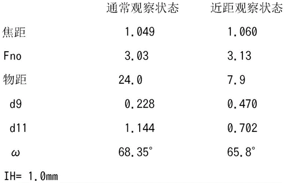
各种数据various data
数值实施例2Numerical Example 2
单位mmUnit mm
面数据face data

各种数据various data

数值实施例3Numerical Example 3
单位mmUnit mm
面数据face data

各种数据various data

数值实施例4Numerical Example 4
单位mmUnit mm
面数据face data

各种数据various data

以下示出各实施例中的条件式对应值。The values corresponding to the conditional expressions in each Example are shown below.

以上,对本发明的各种实施方式进行了说明,但是本发明并不仅仅限于这些实施方式,在不脱离其宗旨的范围内,将这些实施方式的结构适当组合而构成的实施方式也属于本发明的范畴。Various embodiments of the present invention have been described above, but the present invention is not limited only to these embodiments, and embodiments formed by appropriately combining the configurations of these embodiments also belong to the present invention within the scope of not departing from the gist of the present invention. category.
(附记)(Additional note)
此外,从这些实施例导出以下结构的发明。In addition, inventions of the following structures are derived from these Examples.
(附记项1)(Additional item 1)
一种物镜光学系统,其特征在于,An objective optical system, characterized in that:
具有从物体侧起依次配置的正的第一组、负的第二组以及正的第三组,It has a positive first group, a negative second group, and a positive third group arranged in this order from the object side,
通过移动所述第二组来进行调焦,Focusing by moving the second group,
最靠像侧的透镜为使凸面朝向物体侧的平凸正透镜,The lens closest to the image side is a plano-convex positive lens with the convex surface facing the object side.
所述平凸正透镜的平面构成为直接粘贴于摄像面,或者构成为与形成于摄像面上的护罩玻璃接合,The plane of the plano-convex positive lens is configured to be directly attached to the imaging surface, or is configured to be bonded to a cover glass formed on the imaging surface,
所述物镜光学系统满足以下的条件式(1)。The objective optical system satisfies the following conditional expression (1).
5<ff/f<8 (1)5<ff/f<8 (1)
ff为配置于最靠像侧的所述平凸正透镜的焦距,ff is the focal length of the plano-convex positive lens disposed on the most image side,
f为通常观察时的所述物镜光学系统整个系统的焦距。f is the focal length of the entire system of the objective optical system during normal observation.
(附记项2)(Additional item 2)
根据附记项1所记载的物镜光学系统,其特征在于,满足以下的条件式(2)。The objective optical system according to Supplementary Note 1 is characterized in that the following Conditional Expression (2) is satisfied.
-24<fg2/f<-8 (2)-24<fg2/f<-8 (2)
fg2为所述第二组的焦距,fg2 is the focal length of the second group,
f为通常观察时的所述物镜光学系统整个系统的焦距。f is the focal length of the entire system of the objective optical system during normal observation.
(附记项3)(Additional item 3)
根据附记项1或2所记载的物镜光学系统,其特征在于,满足以下的条件式(3)、(4)、(5)、(6)、(7)、(8)、(9)、(10)中的任一个。The objective optical system according to appendix 1 or 2, wherein the following conditional expressions (3), (4), (5), (6), (7), (8), and (9) are satisfied. , any of (10).
2<rf/f<4 (3)2<rf/f<4 (3)
0.15<df/ff<0.4 (4)0.15<df/ff<0.4 (4)
0.2<dn/f<1.2 (5)0.2<dn/f<1.2 (5)
-8<fg2/fg1<-4 (6)-8<fg2/fg1<-4 (6)
-7,6<fg2/fg3<-2.4 (7)-7, 6<fg2/fg3<-2.4 (7)
1.05<r2/f<1.45 (8)1.05<r2/f<1.45 (8)
-0.34<f1/ff<-0.18 (9)-0.34<f1/ff<-0.18 (9)
1.2<df/dn<5.6 (10)1.2<df/dn<5.6 (10)
其中,in,
ff为配置于最靠像侧的所述平凸正透镜的焦距,ff is the focal length of the plano-convex positive lens disposed on the most image side,
f为通常观察时的所述物镜光学系统整个系统的焦距,f is the focal length of the entire system of the objective optical system under normal observation,
rf为配置于最靠像侧的正透镜的物体侧面的曲率半径,rf is the curvature radius of the object side surface of the positive lens arranged on the most image side,
df为从配置于最靠像侧的正透镜的物体侧面到摄像面的距离,df is the distance from the object side of the positive lens arranged on the most image side to the imaging surface,
dn为所述第二组的移动量,dn is the movement amount of the second group,
fg1为所述第一组的焦距,fg1 is the focal length of the first group,
fg2为所述第二组的焦距,fg2 is the focal length of the second group,
fg3为所述第三组的焦距,fg3 is the focal length of the third group,
r2为配置于最靠物体侧的第一透镜的像侧面的曲率半径,r2 is the curvature radius of the image side surface of the first lens disposed on the most object side,
f1为配置于最靠物体侧的第一透镜的焦距。f1 is the focal length of the first lens disposed on the most object side.
(附记项4)(Additional item 4)
一种物镜光学系统,其特征在于,An objective optical system, characterized in that:
具有从物体侧起依次配置的第一组、第二组以及第三组,having a first group, a second group, and a third group arranged in this order from the object side,
通过移动所述第二组来进行调焦,Focusing by moving the second group,
最靠像侧的透镜为使凸面朝向物体侧的平凸正透镜,The lens closest to the image side is a plano-convex positive lens with the convex surface facing the object side.
所述平凸正透镜的平面构成为直接粘贴于摄像面,或者构成为与形成于摄像面上的护罩玻璃接合,The plane of the plano-convex positive lens is configured to be directly attached to the imaging surface, or is configured to be bonded to a cover glass formed on the imaging surface,
所述物镜光学系统满足以下的条件式(1′)。The objective optical system satisfies the following conditional expression (1').
5.5<ff/f<6 (1')5.5<ff/f<6 (1')
其中,in,
ff为配置于最靠像侧的所述平凸正透镜的焦距,ff is the focal length of the plano-convex positive lens disposed on the most image side,
f为通常观察时的所述物镜光学系统的焦距。f is the focal length of the objective optical system during normal observation.
产业上的可利用性Industrial Availability
本发明对于具有调焦功能的物镜光学系统、特别是能够进行近距观察的内窥镜用的物镜光学系统、适合于其它家用的小型摄像机等的摄影透镜的物镜光学系统而言是有用的。The present invention is useful for an objective optical system having a focus adjustment function, in particular, an objective optical system for an endoscope capable of close-up observation, and an objective optical system suitable for photographing lenses such as other home-use compact cameras.
附图标记说明Description of reference numerals
L1~L8:透镜;F1:平行平板;S1:亮度光圈;CG:护罩玻璃;G1:第一组;G2:第二组;G3:第三组;AX:光轴;I:像面(摄像面);IMG:摄像元件;CL1:接合透镜。L1~L8: lens; F1: parallel plate; S1: brightness aperture; CG: cover glass; G1: first group; G2: second group; G3: third group; AX: optical axis; I: image plane ( imaging surface); IMG: imaging element; CL1: cemented lens.
Claims (2)
Applications Claiming Priority (3)
| Application Number | Priority Date | Filing Date | Title |
|---|---|---|---|
| JP2016001142 | 2016-01-06 | ||
| JP2016-001142 | 2016-01-06 | ||
| PCT/JP2016/083354 WO2017119188A1 (en) | 2016-01-06 | 2016-11-10 | Objective optical system |
Publications (2)
| Publication Number | Publication Date |
|---|---|
| CN108474926A CN108474926A (en) | 2018-08-31 |
| CN108474926B true CN108474926B (en) | 2020-09-29 |
Family
ID=59273559
Family Applications (1)
| Application Number | Title | Priority Date | Filing Date |
|---|---|---|---|
| CN201680078238.3A Active CN108474926B (en) | 2016-01-06 | 2016-11-10 | Objective optical system |
Country Status (5)
| Country | Link |
|---|---|
| US (1) | US10649201B2 (en) |
| EP (1) | EP3401718A4 (en) |
| JP (1) | JP6197147B1 (en) |
| CN (1) | CN108474926B (en) |
| WO (1) | WO2017119188A1 (en) |
Families Citing this family (14)
| Publication number | Priority date | Publication date | Assignee | Title |
|---|---|---|---|---|
| CN109313324B (en) * | 2016-06-20 | 2021-02-23 | 奥林巴斯株式会社 | Objective optical system for endoscope |
| WO2018092619A1 (en) * | 2016-11-16 | 2018-05-24 | オリンパス株式会社 | Objective optical system |
| JP6857572B2 (en) * | 2017-08-07 | 2021-04-14 | オリンパス株式会社 | Objective optical system for endoscopes |
| TWI684024B (en) | 2018-07-04 | 2020-02-01 | 大立光電股份有限公司 | Photographing optical lens assembly, imaging apparatus and electronic device |
| WO2020174561A1 (en) * | 2019-02-26 | 2020-09-03 | オリンパス株式会社 | Endoscope objective optical system |
| JP7104854B2 (en) | 2019-04-10 | 2022-07-21 | オリンパス株式会社 | Endoscope Objective optical system and endoscope |
| CN113646683B (en) * | 2019-04-26 | 2023-04-11 | 奥林巴斯株式会社 | Endoscope objective optical system |
| CN112485883B (en) * | 2019-09-11 | 2022-03-29 | 信泰光学(深圳)有限公司 | Imaging lens |
| CN114355598B (en) * | 2020-10-13 | 2025-08-05 | 厦门松下电子信息有限公司 | Large-aperture internal focusing optical system |
| CN112462501B (en) * | 2020-12-17 | 2025-05-02 | 浙江舜宇光学有限公司 | Optical imaging system |
| WO2022165102A1 (en) | 2021-01-29 | 2022-08-04 | Caronia Ronald Michael | Opthalmic instrument eyepiece extender |
| US12468120B2 (en) * | 2021-07-05 | 2025-11-11 | Sintai Optical (Shenzhen) Co., Ltd. | Wide-angle lens assembly |
| CN114442299B (en) * | 2021-12-30 | 2024-03-19 | 宁波永新光学股份有限公司 | An optical imaging system for a dental operating microscope |
| CN118859492B (en) * | 2024-09-26 | 2025-03-11 | 江西联益光学有限公司 | Optical lens |
Family Cites Families (26)
| Publication number | Priority date | Publication date | Assignee | Title |
|---|---|---|---|---|
| JPS5590928A (en) | 1978-12-29 | 1980-07-10 | Olympus Optical Co Ltd | Endoscope objective lens which performs changing of magnification and focusing simultaneously |
| JPS6046410B2 (en) * | 1980-10-08 | 1985-10-16 | オリンパス光学工業株式会社 | endoscope objective lens |
| JPS60263916A (en) * | 1984-06-13 | 1985-12-27 | Olympus Optical Co Ltd | Retrofocus type varifocal objective lens for endoscope |
| JP2628627B2 (en) * | 1985-01-11 | 1997-07-09 | オリンパス光学工業株式会社 | Aspheric objective lens for endoscope |
| JP2596810B2 (en) * | 1988-09-12 | 1997-04-02 | オリンパス光学工業株式会社 | Optical system for endoscope |
| US5223982A (en) * | 1991-03-05 | 1993-06-29 | Olympus Optical Co., Ltd. | Objective lens system for endoscopes |
| JP3349766B2 (en) | 1993-04-30 | 2002-11-25 | オリンパス光学工業株式会社 | Endoscope objective optical system |
| JP3765500B2 (en) | 1993-12-24 | 2006-04-12 | オリンパス株式会社 | Endoscope objective lens |
| JPH11316339A (en) | 1998-03-03 | 1999-11-16 | Olympus Optical Co Ltd | Objective optical system |
| JP4003851B2 (en) | 1998-03-12 | 2007-11-07 | 株式会社アルバック | Thin film forming apparatus and plasma source thereof |
| JP3713386B2 (en) * | 1998-08-25 | 2005-11-09 | オリンパス株式会社 | Endoscope |
| JP2000267002A (en) * | 1999-03-15 | 2000-09-29 | Olympus Optical Co Ltd | Optical system |
| EP1211543A4 (en) * | 1999-09-08 | 2006-08-30 | Olympus Optical Corp Ltd | Image pickup optical system for endoscope |
| JP3337666B2 (en) * | 1999-10-15 | 2002-10-21 | オリンパス光学工業株式会社 | Objective lens |
| JP4289914B2 (en) * | 2002-05-07 | 2009-07-01 | キヤノン株式会社 | Imaging optical system and image reading apparatus using the same |
| US6950241B1 (en) * | 2002-09-18 | 2005-09-27 | Dmetrix, Inc. | Miniature microscope objective for an array microscope |
| JP4346977B2 (en) * | 2003-07-03 | 2009-10-21 | 株式会社リコー | Variable focal length lens, photographing lens unit, camera, and portable information terminal device |
| JP4685510B2 (en) * | 2005-05-24 | 2011-05-18 | 富士フイルム株式会社 | Endoscope objective lens |
| JP5185578B2 (en) * | 2007-08-22 | 2013-04-17 | オリンパス株式会社 | Small-diameter objective optical system |
| CN101815969B (en) * | 2007-10-02 | 2013-07-17 | 卡尔蔡司Smt有限责任公司 | Projection objective for microlithography |
| JP2009163256A (en) * | 2009-03-03 | 2009-07-23 | Olympus Corp | Optical system |
| JP5687572B2 (en) * | 2011-06-14 | 2015-03-18 | オリンパス株式会社 | Imaging optical system and endoscope apparatus including the same |
| EP2871508A4 (en) * | 2012-07-03 | 2016-03-23 | Olympus Corp | Objective optical system for endoscope |
| WO2014132494A1 (en) * | 2013-02-28 | 2014-09-04 | オリンパスメディカルシステムズ株式会社 | Objective optical system |
| EP3015895A4 (en) * | 2013-06-26 | 2017-01-04 | Olympus Corporation | Endoscope objective optical system |
| CN105378535B (en) * | 2013-08-22 | 2017-12-05 | 奥林巴斯株式会社 | Objective optical system for endoscope |
-
2016
- 2016-11-10 CN CN201680078238.3A patent/CN108474926B/en active Active
- 2016-11-10 WO PCT/JP2016/083354 patent/WO2017119188A1/en not_active Ceased
- 2016-11-10 EP EP16883688.0A patent/EP3401718A4/en not_active Withdrawn
- 2016-11-10 JP JP2017516528A patent/JP6197147B1/en active Active
-
2018
- 2018-07-02 US US16/025,745 patent/US10649201B2/en active Active
Also Published As
| Publication number | Publication date |
|---|---|
| CN108474926A (en) | 2018-08-31 |
| JP6197147B1 (en) | 2017-09-13 |
| EP3401718A1 (en) | 2018-11-14 |
| WO2017119188A1 (en) | 2017-07-13 |
| JPWO2017119188A1 (en) | 2018-01-11 |
| EP3401718A4 (en) | 2019-09-04 |
| US10649201B2 (en) | 2020-05-12 |
| US20180314054A1 (en) | 2018-11-01 |
Similar Documents
| Publication | Publication Date | Title |
|---|---|---|
| CN108474926B (en) | Objective optical system | |
| US8203798B2 (en) | Objective optical system | |
| JP6266189B1 (en) | Objective optical system | |
| CN105074531B (en) | Amplify endoscope optical system | |
| JP7249486B2 (en) | IMAGING OPTICAL SYSTEM AND IMAGING APPARATUS AND CAMERA SYSTEM INCLUDING THE SAME | |
| JP5818209B2 (en) | Macro lens | |
| JP6548590B2 (en) | Imaging lens and imaging apparatus | |
| CN106062609A (en) | Objective optical system | |
| JP6501984B2 (en) | Objective optical system | |
| JP6468978B2 (en) | Imaging lens and imaging apparatus | |
| JP6219183B2 (en) | Imaging lens and imaging apparatus | |
| JP4981466B2 (en) | Optical system and imaging apparatus having the same | |
| CN109923458B (en) | Objective optical system | |
| JP4578869B2 (en) | 3 group zoom lens | |
| WO2013175722A1 (en) | Zoom lens and imaging device | |
| JP5217694B2 (en) | Lens system and optical device | |
| JP2005037935A (en) | Compact lightweight zoom lens | |
| JP6836466B2 (en) | Endoscopic objective optical system | |
| JP5037960B2 (en) | Optical system and imaging apparatus having the same | |
| JP5006627B2 (en) | Optical system and optical apparatus having the same | |
| JP7690351B2 (en) | Imaging lens and imaging device | |
| CN113646683A (en) | Endoscope objective optical system | |
| KR20110072199A (en) | Zoom lens optical system and imaging device having same |
Legal Events
| Date | Code | Title | Description |
|---|---|---|---|
| PB01 | Publication | ||
| PB01 | Publication | ||
| SE01 | Entry into force of request for substantive examination | ||
| SE01 | Entry into force of request for substantive examination | ||
| GR01 | Patent grant | ||
| GR01 | Patent grant |