CN1084043C - Magnetic correction circuit and picture display using same - Google Patents
Magnetic correction circuit and picture display using same Download PDFInfo
- Publication number
- CN1084043C CN1084043C CN95191706A CN95191706A CN1084043C CN 1084043 C CN1084043 C CN 1084043C CN 95191706 A CN95191706 A CN 95191706A CN 95191706 A CN95191706 A CN 95191706A CN 1084043 C CN1084043 C CN 1084043C
- Authority
- CN
- China
- Prior art keywords
- magnetic
- lead
- correction circuit
- coil
- amorphous
- Prior art date
- Legal status (The legal status is an assumption and is not a legal conclusion. Google has not performed a legal analysis and makes no representation as to the accuracy of the status listed.)
- Expired - Fee Related
Links
- 230000005291 magnetic effect Effects 0.000 title claims abstract description 190
- 230000005389 magnetism Effects 0.000 claims description 11
- 238000001514 detection method Methods 0.000 claims description 9
- 239000004020 conductor Substances 0.000 claims description 7
- 230000004907 flux Effects 0.000 description 4
- 238000005259 measurement Methods 0.000 description 4
- 230000035945 sensitivity Effects 0.000 description 4
- 238000010894 electron beam technology Methods 0.000 description 3
- 230000005307 ferromagnetism Effects 0.000 description 2
- 239000000463 material Substances 0.000 description 2
- 239000000203 mixture Substances 0.000 description 2
- 230000001915 proofreading effect Effects 0.000 description 2
- 102000016871 Hexosaminidase A Human genes 0.000 description 1
- 108010053317 Hexosaminidase A Proteins 0.000 description 1
- 239000000956 alloy Substances 0.000 description 1
- 229910045601 alloy Inorganic materials 0.000 description 1
- 238000000137 annealing Methods 0.000 description 1
- 239000000470 constituent Substances 0.000 description 1
- 238000001816 cooling Methods 0.000 description 1
- 238000010586 diagram Methods 0.000 description 1
- 230000000694 effects Effects 0.000 description 1
- 238000005516 engineering process Methods 0.000 description 1
- 230000005284 excitation Effects 0.000 description 1
- 230000004927 fusion Effects 0.000 description 1
- 238000007689 inspection Methods 0.000 description 1
- 230000005415 magnetization Effects 0.000 description 1
- 238000004519 manufacturing process Methods 0.000 description 1
Images


Classifications
-
- G—PHYSICS
- G01—MEASURING; TESTING
- G01R—MEASURING ELECTRIC VARIABLES; MEASURING MAGNETIC VARIABLES
- G01R33/00—Arrangements or instruments for measuring magnetic variables
- G01R33/02—Measuring direction or magnitude of magnetic fields or magnetic flux
- G01R33/04—Measuring direction or magnitude of magnetic fields or magnetic flux using the flux-gate principle
-
- G—PHYSICS
- G01—MEASURING; TESTING
- G01R—MEASURING ELECTRIC VARIABLES; MEASURING MAGNETIC VARIABLES
- G01R33/00—Arrangements or instruments for measuring magnetic variables
- G01R33/02—Measuring direction or magnitude of magnetic fields or magnetic flux
- G01R33/025—Compensating stray fields
-
- G—PHYSICS
- G01—MEASURING; TESTING
- G01R—MEASURING ELECTRIC VARIABLES; MEASURING MAGNETIC VARIABLES
- G01R33/00—Arrangements or instruments for measuring magnetic variables
- G01R33/02—Measuring direction or magnitude of magnetic fields or magnetic flux
- G01R33/06—Measuring direction or magnitude of magnetic fields or magnetic flux using galvano-magnetic devices
- G01R33/063—Magneto-impedance sensors; Nanocristallin sensors
-
- H—ELECTRICITY
- H01—ELECTRIC ELEMENTS
- H01J—ELECTRIC DISCHARGE TUBES OR DISCHARGE LAMPS
- H01J29/00—Details of cathode-ray tubes or of electron-beam tubes of the types covered by group H01J31/00
- H01J29/003—Arrangements for eliminating unwanted electromagnetic effects, e.g. demagnetisation arrangements, shielding coils
-
- H—ELECTRICITY
- H04—ELECTRIC COMMUNICATION TECHNIQUE
- H04N—PICTORIAL COMMUNICATION, e.g. TELEVISION
- H04N9/00—Details of colour television systems
- H04N9/12—Picture reproducers
- H04N9/16—Picture reproducers using cathode ray tubes
- H04N9/29—Picture reproducers using cathode ray tubes using demagnetisation or compensation of external magnetic fields
-
- H—ELECTRICITY
- H01—ELECTRIC ELEMENTS
- H01J—ELECTRIC DISCHARGE TUBES OR DISCHARGE LAMPS
- H01J2229/00—Details of cathode ray tubes or electron beam tubes
- H01J2229/0007—Elimination of unwanted or stray electromagnetic effects
- H01J2229/003—Preventing or cancelling fields entering the enclosure
- H01J2229/0038—Active means
Landscapes
- Physics & Mathematics (AREA)
- Condensed Matter Physics & Semiconductors (AREA)
- General Physics & Mathematics (AREA)
- Engineering & Computer Science (AREA)
- Multimedia (AREA)
- Nanotechnology (AREA)
- Chemical & Material Sciences (AREA)
- Signal Processing (AREA)
- Electromagnetism (AREA)
- Measuring Magnetic Variables (AREA)
- Video Image Reproduction Devices For Color Tv Systems (AREA)
- Electrodes For Cathode-Ray Tubes (AREA)
- Details Of Television Scanning (AREA)
- Hall/Mr Elements (AREA)
Abstract
The invention discloses a magnetic correction circuit and the display device of images using it which is provided with a magnetic sensor (1), a control circuit (2) which generates a signal for magnetic correction, and a coil (3) for magnetic correction. The sensor is provided with a pair of amorphous magnetic wires (101) arranged in parallel with each other, coils (102) which respectively impress bias magnetic fields in the opposite directions upon the wires, high-frequency power source (105) which supplies a high-frequency current to the wires, and circuits (106, 107, 108, and 109) for outputting the difference between the voltages at the output terminals of the wires. The magnetic correction circuit can detect even a very weak external magnetic field with a good accuracy.
Description
Technical field
The present invention relates to magnetic correction circuit and use its image display device.This magnetic correction circuit, magnetic that detects earth magnetism, produces by the part of constituent apparatus and the magnetic that produces by Magnetic Sensor (below be called external magnetic), and corresponding to detected magnetic, produce magnetic and proofread and correct external magnetic thus, prevent colorimetric purity (Purity) skew of going into the such image display device of the skew of screen point and CRT of electron beam.
Background technology
In the past, known have with earth magnetism (tens thousand of nT, tens of A/m) as the flux gate type Magnetic Sensor that carries out the high Precision Detection Magnetic Sensor.Must need large-scale magnetic core on the flux gate type Magnetic Sensor principle, therefore, can not do the head of transducer little.For this reason, existing problems in the magnetic measurement sensor of using as the magnetic correction circuit of the colorimetric purity skew etc. that prevents image display device uses.Flux gate type Magnetic Sensor expense height, be not suitable for a large amount of productions.
In the Magnetic Sensor beyond the flux gate type Magnetic Sensor, useful semi-conductive hole element, with the magnetoresistive element of ferromagnetism body (following " ferromagnetism body " abbreviates " magnetic " as) film etc.But these Magnetic Sensors, magnetic field detection sensitivity are low, in the magnetic measurement sensor of using as the magnetic correction circuit of the colorimetric purity skew that prevents image display device etc. uses, use the transducer of high price and the circuit of complexity because of having to, so expense increases.Therefore, can high-precision correction the correcting circuit of external magnetic, only rest on and be assembled in a part of high vision display unit.
If allow level with earth magnetism (tens thousand of nT, tens of A/m) as its peak signal, then there is the low problem of magnetic accuracy of detection in Magnetic Sensor in the past.
Therefore, the purpose of this invention is to provide and have abundant precision and small-sized inexpensive magnetic correction circuit so that device also can detect small external magnetic field after making.
In addition, the purpose of this invention is to provide the image display device that possesses magnetic correction circuit of the present invention.
Summary of the invention
Magnetic correction circuit of the present invention, it is characterized in that, has Magnetic Sensor, produce magnetic and proofread and correct control circuit and the magnetic correction coil of using signal, detect the quantity of magnetism of external magnetic with this Magnetic Sensor, with the magnetic correction signal of this control circuit generation corresponding to the quantity of magnetism of the external magnetic of described detection, cross this signal in this magnetic correction with coil midstream, by means of the magnetic that produces ormal weight at the magnetic sensing direction of this Magnetic Sensor, proofread and correct in the magnetic correction circuit of external magnetic, described Magnetic Sensor comprises the amorphous magnetic lead of pair of parallel configuration, coil that is provided with respectively on this a pair of amorphous magnetic lead or permanent magnet are so that provide the bias magnetic field of mutual relative direction, be used on described couple of conductor, providing the high frequency electric source of high-frequency current and be used to export the circuit of the voltage difference that obtains from each output of described couple of conductor.
Magnetic correction circuit of the present invention is characterized in that, has two groups or three groups of aforesaid Magnetic Sensors and magnetic and proofreaies and correct the combination of the coil of usefulness, and they are configured to mutually orthogonal.
In addition, image display device of the present invention is characterized in that, it comprises aforesaid magnetic correction circuit.
Magnetic Sensor detects the quantity of magnetism of external magnetic, and control circuit produces corresponding to being proofreaied and correct by the magnetic of the quantity of magnetism of the detected external magnetic of Magnetic Sensor and uses signal.Proofread and correct at this magnetic and to cross this signal, produce the magnetic of ormal weight, thus, proofread and correct external magnetic at the magnetic sensing direction of this Magnetic Sensor with coil midstream.Prevent that for example the screen of going into of the electron beam of image display apparatus is put skew and colorimetric purity skew.
Brief Description Of Drawings
Fig. 1 represents the circuit diagram of the structure example of magnetic correction circuit related to the present invention and image display device.
Fig. 2 represents the figure of the circuit structure example of the Magnetic Sensor that uses in the present invention.
Fig. 3 represents to be used for applying the external magnetic field on the long axis direction of amorphous magnetic lead and the figure of the basic circuit structure example of lead both end voltage during at its two ends measurements energising high-frequency current.
Fig. 4 is that the external magnetic field of measuring circuit measurement shown in Figure 3 and the figure of lead both end voltage relation are used in expression.
The best mode that carries out an invention
Below, with reference to accompanying drawing embodiments of the invention are at length described.
In Fig. 1, the 1st, the Magnetic Sensor of equipment on as the electron gun part of the image display device 4 of CRT, the 2nd, the control circuit of the generation magnetic correction signal that is connected with Magnetic Sensor 1 output, the 3rd, connect with the output of control circuit, near the electron gun of CRT4 in same plane the generation of relative configuration to the coil of unidirectional magnetic field for correcting.
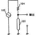
In Fig. 2, the 101st, amorphous magnetic lead, the 102nd, be used for providing the coil of bias magnetic field at amorphous magnetic lead 101, the 103rd, the external magnetic detecting unit of forming by amorphous magnetic lead 101 and line chart 102, the 104th, resistance, the 105th, be used for high frequency electric source at amorphous magnetic lead 101 energising high-frequency currents, the 106th, amplifier, the 107th, wave detector, the 108th, low pass filter, the 109th, differential amplifier.As shown in the figure, external magnetic detecting unit 103 is connected in parallel for high frequency electric source 105 with resistance 104 and configuration abreast, and the signal of exporting from amorphous magnetic lead 101 takes out and be input to amplifier 106 from the tie point with resistance 104 respectively.
The amorphous magnetic lead 101 of Shi Yonging is that the hypervelocity cooling becomes wire behind the alloy of other composition of CoSiB series, FeCoSiB series fusion in the present invention.In addition, implement to be used to align the tension force annealing down of magnetostriction constant, each guide property of magnetic, on the circumferencial direction of amorphous magnetic lead 101, have strong magnetic anisotropy.If about magnetostriction constant lambda s because of magnetostriction constant lambda s greater than 10
-6, lead both end voltage described later just diminishes, is difficult to detect, so, be desirably in-10
-6Use in the scope of≤λ s≤0.The diameter of amorphous magnetic lead 101 is greatly gratifying in scope, the detection sensitivity of 10~150 μ m, though length can be used about 1mm, is desirably in more than the 2mm from easy output.
Constitute magnetic correction circuit related to the present invention as described above like that, below its effect is described.
On the long axis direction of amorphous magnetic lead 101, when utilizing high frequency electric source 105 energising high-frequency currents, just produce voltage at the two ends of amorphous magnetic lead 101, around amorphous magnetic lead 101, produce the circumference magnetic field H simultaneously
0, because of amorphous magnetic lead 101 is magnetics, so have intrinsic inductance L and D.C. resistance R (resistance that also comprises eddy current loss).Here, on the long axis direction of amorphous magnetic lead 101, when applying external magnetic field Hex, the magnetization vector M of amorphous magnetic lead 101 just only tilts corresponding to the angle φ (0 °<φ<90 °) of the intensity of external magnetic field Hex.Its result, the effective magnetizing composition of circumferencial direction is MCos φ (0<Cos φ<1), aforementioned inductance L and D.C. resistance R also reduce.
Therefore, variation from this impedance, can detect the intensity of the external magnetic field Hex on the long axis direction be applied to amorphous magnetic lead 101, and the variation of impedance is tried to achieve in the variation of the lead both end voltage can be from the long axis direction energising high-frequency current of amorphous magnetic lead 101 time.
Fig. 3 represents to be used for applying external magnetic field HexA/m on the long axis direction of amorphous magnetic lead 101, measuring the basic circuit at the lead both end voltage mVp-p of the two ends of amorphous magnetic lead 101 energising during from the high-frequency current of high frequency electric source 105.And Fig. 4 is illustrated in by (Fe
6Co
94)
72.5Si
125B
15Be connected in series in the amorphous magnetic lead 101 that constitutes the resistance 104 of 100 (Ω), be the variation of lead both end voltage mVp-p of the external magnetic field Hex A/m of 300kHz occasion corresponding to the frequency of high-frequency current.
In the figure of Fig. 4, externally near magnetic field H ex ± 200A/m, the lead both end voltage becomes maximum, and is that the boundary becomes left-right symmetric with outside magnetic field H ex=0.Based on the frequency of the material of amorphous magnetic lead 101, shape, electrical current and current value etc., the state difference of graph curve, but no matter which kind of situation to be symmetry axis and the curve that becomes the symmetric form of mountain peak shape with the ordinate of Hex=0 all in.Therefore, be occasion more than the 55mVp-p in the lead both end voltage, the intensity of external magnetic field Hex can not be determined uniquely, can not detect external magnetic field Hex.
Therefore, in the present invention, dispose magnetic detecting unit 103 in parallel to each other, 10~300kHz high-frequency current of in each amorphous magnetic lead 101, switching on, on paired coil 102, produce the opposite bias magnetic field of intensity equidirectional, lead both end voltage with each amorphous magnetic lead 101 of the electric circuit inspection shown in the square frame among Fig. 2 is poor, tries to achieve the intensity of external magnetic field Hex of the long axis direction of magnetic detecting unit 103.That is to say, for example in Fig. 3, if getting bias magnetic field is respectively+500A/m and-500A/m, then can utilize+200A/m~+ 500A/m and-200A/m~-curve of 500A/m scope, if it is poor to try to achieve the both end voltage of couple of conductor, then can utilize ± curve of 300A/m scope, and, if it is poor to try to achieve the both end voltage of couple of conductor, then can measure intensity and the direction of external magnetic field Hex in ± 300A/m scope, accuracy of detection at the Magnetic Sensor of aforementioned condition is 1A/m, and peak signal allows that level can obtain sufficient magnetic detection sensitivity in the occasion of earth magnetism degree.
Therefore, the signal of the difference of the couple of conductor both end voltage that expression obtains from the output of differential amplifier 109 is input to the control circuit 2, proofreaies and correct corresponding to the magnetic of input signal size and outputs to coil 3 with signal from control circuit 2, suitably proofreaies and correct the external magnetic field.In this occasion, the peak signal of usefulness ± 300A/m allows that level can make the magnetic of 1A/m precision and proofread and correct.
Then, according to previous embodiment experimental result is described.
The direction of proofreading and correct the magnetic field for correcting that produces with coil 3 from magnetic is harmonious, also can detects with Magnetic Sensor 1 magnetic field that produces with coil 3 from proofreading and correct with the direction that detects with Magnetic Sensor 1.When carrying out magnetic field correction in this way, then magnetic correction circuit automatically moves, until proofread and correct from magnetic become 0 (A/m) with the magnetic field for correcting of coil 3 generations and external magnetic field till.
Use magnetostriction constant lambda s=-10
-7, diameter 50 μ m, effective length 4mm, by (Fe
6Co
94)
72.5Si
125B
15Constitute amorphous magnetic lead 101.At the coil 102 that is used for applied shifts magnetic field, produce the bias magnetic field of 500A/m with the number of turns 100 circles, coil diameter 3mm.Resistance 1 ± 04 is 270 Ω, and the frequency f of the high-frequency current of energising is 300kHz in each amorphous magnetic lead 101.
Satisfying the Magnetic Sensor 1 of aforementioned condition, can be 10mm * 10mm * 5mm with magnetic detecting unit 103, and integral body is that the size of 30mm * 30mm * 5mm is made.The magnetic direction that detects with Magnetic Sensor 1 is as ground magnetic strength vertical direction, proofreaies and correct the magnetic direction that produces with coil 3 with magnetic as can be with the vertical direction of Magnetic Sensor 1 detection.
Magnetic is proofreaied and correct and is used the square of the thick enamelled wire of coil 3 usefulness 0.1mm around 100 circles, one-tenth 100mm * 100mm, and the CRT4 size is with 17 inches.
Even its result from the outside magnetic field that applies 300A/m, can not produce the colorimetric purity skew yet and can obtain distinct image.
In above embodiment, though on same plane (paper), dispose amorphous magnetic lead 101 abreast as Magnetic Sensor 1 with one group, and proofread and correct with one group of magnetic and to be configured in same plane (paper) up and down with coil 3 and to go up, they respectively one group are configured in form on two of quadrature or three planes but also can make so that seize the electron gun of CRT4 on both sides by the arms.In the magnetic of image display device detected, there were horizontal component and vertical component in the magnetic field of sending because of the part from earth magnetism and image display device, so expectation respectively one group is configured in the form on two of quadrature or three planes.In addition, magnetic is proofreaied and correct can be varied to various sizes and shape according to the place of magnetic field for correcting with coil 3, also can freely design according to the structure of image display device.
Industrial practicality
As previously mentioned, magnetic correction circuit of the present invention can consist of on minimal type ground, and is aobvious at the image that uses it Can do not produced the excitation skew that enters screen point skew and CRT of electron beam in the showing device clearly Image from now on, can have very big contribution to the image display device industrial quarters of the continuous high quality of picture.
Claims (4)
1. magnetic correction circuit, it is characterized in that, has Magnetic Sensor, produce magnetic and proofread and correct control circuit and the magnetic correction coil of using signal, detect the quantity of magnetism of external magnetic with this Magnetic Sensor, with the magnetic correction signal of this control circuit generation corresponding to the quantity of magnetism of the external magnetic of described detection, cross this signal in this magnetic correction with coil midstream, by means of the magnetic that produces ormal weight at the magnetic sensing direction of this Magnetic Sensor, proofread and correct in the magnetic correction circuit of external magnetic, described Magnetic Sensor comprises the amorphous magnetic lead of pair of parallel configuration, coil that is provided with respectively on this a pair of amorphous magnetic lead or permanent magnet are so that provide the bias magnetic field of mutual relative direction, be used on described couple of conductor, providing the high frequency electric source of high-frequency current and be used to export the circuit of the voltage difference that obtains from each output of described couple of conductor.
2. magnetic correction circuit as claimed in claim 1 is characterized in that, has two groups or three groups of described Magnetic Sensors and magnetic and proofreaies and correct the combination of the coil of usefulness, and they are configured to mutually orthogonal.
3. as claim 1 or the described magnetic correction circuit of claim 2, it is characterized in that described amorphous magnetic lead is by (Fe
6Co
94)
72.5Si
12.5B
15Constitute.
4. an image display device is characterized in that, it comprises as claim 1 or the described magnetic correction circuit of claim 2.
Applications Claiming Priority (2)
| Application Number | Priority Date | Filing Date | Title |
|---|---|---|---|
| JP319825/94 | 1994-12-22 | ||
| JP6319825A JPH08179020A (en) | 1994-12-22 | 1994-12-22 | Magnetic correcting circuit and image display device using it |
Publications (2)
| Publication Number | Publication Date |
|---|---|
| CN1141689A CN1141689A (en) | 1997-01-29 |
| CN1084043C true CN1084043C (en) | 2002-05-01 |
Family
ID=18114634
Family Applications (1)
| Application Number | Title | Priority Date | Filing Date |
|---|---|---|---|
| CN95191706A Expired - Fee Related CN1084043C (en) | 1994-12-22 | 1995-12-14 | Magnetic correction circuit and picture display using same |
Country Status (6)
| Country | Link |
|---|---|
| US (1) | US5751112A (en) |
| JP (1) | JPH08179020A (en) |
| KR (1) | KR100267207B1 (en) |
| CN (1) | CN1084043C (en) |
| GB (1) | GB2301515B (en) |
| WO (1) | WO1996019819A1 (en) |
Families Citing this family (13)
| Publication number | Priority date | Publication date | Assignee | Title |
|---|---|---|---|---|
| JP3614588B2 (en) * | 1996-12-06 | 2005-01-26 | 独立行政法人科学技術振興機構 | High sensitivity stress detector |
| EP0855599A3 (en) * | 1997-01-24 | 2001-05-02 | Siemens Aktiengesellschaft | Electronic compass |
| EP0892276A3 (en) * | 1997-07-14 | 2001-05-30 | Alps Electric Co., Ltd. | Magnetic sensor |
| KR100265379B1 (en) * | 1997-11-05 | 2000-09-15 | 윤종용 | Geomagnetic field deflection automatic correction device |
| JPH11202035A (en) * | 1997-11-17 | 1999-07-30 | Unitika Ltd | Magnetic sensor element |
| US6894450B2 (en) * | 2002-01-16 | 2005-05-17 | Ballard Power Systems Corporation | Circuit configuration for permanent magnet synchronous motor control |
| SE529125C2 (en) * | 2005-03-02 | 2007-05-08 | Tetra Laval Holdings & Finance | Method and apparatus for determining the position of a packaging material with magnetic markings |
| JP4928752B2 (en) * | 2005-07-14 | 2012-05-09 | 株式会社東芝 | Semiconductor memory device |
| JP5110142B2 (en) * | 2010-10-01 | 2012-12-26 | 愛知製鋼株式会社 | Magnetoimpedance sensor element and manufacturing method thereof |
| DE102012214892A1 (en) * | 2012-08-22 | 2014-02-27 | Fraunhofer-Gesellschaft zur Förderung der angewandten Forschung e.V. | magnetic field sensor |
| JP6281677B2 (en) * | 2013-03-08 | 2018-02-21 | 国立大学法人名古屋大学 | Magnetic measuring device |
| DE112016005046T5 (en) * | 2015-11-04 | 2018-08-02 | Tdk Corporation | Magnetic field detection device and magnetic field detection method |
| CN119199662A (en) * | 2024-09-20 | 2024-12-27 | 上海渺知科技有限公司 | Direct-insertion three-axis wide-band magnetic field sensor, preparation method and application method |
Citations (2)
| Publication number | Priority date | Publication date | Assignee | Title |
|---|---|---|---|---|
| JPS5441137B2 (en) * | 1973-04-16 | 1979-12-06 | ||
| US5017832A (en) * | 1989-02-06 | 1991-05-21 | Mitsubishi Denki Kaisha Kaisha | Magnetic cancelling apparatus for color cathode-ray tube |
Family Cites Families (13)
| Publication number | Priority date | Publication date | Assignee | Title |
|---|---|---|---|---|
| JPS4541137B1 (en) * | 1967-09-20 | 1970-12-23 | ||
| JPS60160791A (en) * | 1984-02-01 | 1985-08-22 | Yamatake Honeywell Co Ltd | Cathode-ray tube |
| JPS61245002A (en) * | 1985-04-22 | 1986-10-31 | Kaneo Mori | Non-contact type linear displacement sensor |
| JPH0651899B2 (en) * | 1985-07-26 | 1994-07-06 | ユニチカ株式会社 | Amorphous metal wire |
| JPS62239020A (en) * | 1986-04-11 | 1987-10-19 | Unitika Ltd | Rotary sensor |
| US4734519A (en) * | 1986-06-05 | 1988-03-29 | Mallinckrodt, Inc. | Pentaerythritol co-esters |
| JPS641981A (en) * | 1987-06-25 | 1989-01-06 | Fuji Electric Co Ltd | Magnetic field detector |
| JPH01155282A (en) * | 1987-12-14 | 1989-06-19 | Toyota Autom Loom Works Ltd | Magnetic sensor |
| US4939459A (en) * | 1987-12-21 | 1990-07-03 | Tdk Corporation | High sensitivity magnetic sensor |
| US4996461A (en) * | 1989-09-07 | 1991-02-26 | Hughes Aircraft Company | Closed loop bucking field system |
| JP2857177B2 (en) * | 1989-10-05 | 1999-02-10 | 日本フェルト株式会社 | Structure for detecting the orbital reference position of magnetic object and needle felt manufacturing equipment |
| JPH03252577A (en) * | 1990-03-02 | 1991-11-11 | Unitika Ltd | Magnetic field detecting method and magnetic field sensor |
| JPH07333305A (en) * | 1994-06-07 | 1995-12-22 | Kaneo Mori | Magnetic inductance effect element |
-
1994
- 1994-12-22 JP JP6319825A patent/JPH08179020A/en active Pending
-
1995
- 1995-12-14 KR KR1019960704544A patent/KR100267207B1/en not_active IP Right Cessation
- 1995-12-14 CN CN95191706A patent/CN1084043C/en not_active Expired - Fee Related
- 1995-12-14 WO PCT/JP1995/002563 patent/WO1996019819A1/en active Application Filing
- 1995-12-14 GB GB9616560A patent/GB2301515B/en not_active Expired - Fee Related
-
1996
- 1996-08-15 US US08/698,389 patent/US5751112A/en not_active Expired - Fee Related
Patent Citations (2)
| Publication number | Priority date | Publication date | Assignee | Title |
|---|---|---|---|---|
| JPS5441137B2 (en) * | 1973-04-16 | 1979-12-06 | ||
| US5017832A (en) * | 1989-02-06 | 1991-05-21 | Mitsubishi Denki Kaisha Kaisha | Magnetic cancelling apparatus for color cathode-ray tube |
Also Published As
| Publication number | Publication date |
|---|---|
| KR100267207B1 (en) | 2000-10-16 |
| CN1141689A (en) | 1997-01-29 |
| US5751112A (en) | 1998-05-12 |
| WO1996019819A1 (en) | 1996-06-27 |
| JPH08179020A (en) | 1996-07-12 |
| GB2301515A (en) | 1996-12-04 |
| GB2301515B (en) | 1998-10-07 |
| GB9616560D0 (en) | 1996-09-25 |
Similar Documents
| Publication | Publication Date | Title |
|---|---|---|
| CN1084043C (en) | Magnetic correction circuit and picture display using same | |
| US6642714B2 (en) | Thin-film magnetic field sensor | |
| EP2801834B1 (en) | Current sensor | |
| EP3006951B1 (en) | Single-chip bridge-type magnetic field sensor | |
| Ripka | Sensors based on bulk soft magnetic materials: Advances and challenges | |
| US5757184A (en) | Magnetic field detection apparatus with bilateral electrical switch for inverting magnetic sensor current | |
| CN110260770A (en) | Magnetic Sensor and position detecting device | |
| US20160041236A1 (en) | Magnetism measurement device | |
| US5142227A (en) | Method and apparatus for measuring strain within a ferromagnetic material by sensing change in coercive field | |
| RU2737782C1 (en) | Element for detecting a three-dimensional magnetic field and a device for detecting a three-dimensional magnetic field | |
| US6452382B1 (en) | Encoder provided with giant magnetoresistive effect elements | |
| Ripka | Contactless measurement of electric current using magnetic sensors | |
| US3271665A (en) | Thin film field sensor | |
| JP3764834B2 (en) | Current sensor and current detection device | |
| US4963818A (en) | Current sensor having an element made of amorphous magnetic metal | |
| Kraus | A novel method for measurement of the saturation magnetostriction of amorphous ribbons | |
| Kashiwagi et al. | 300 A current sensor using amorphous wire core (invertor control of AC motors) | |
| Hristoforou et al. | A new magnetic field sensor based on magnetostrictive delay lines | |
| WO2024034169A1 (en) | Magnetic sensor and magnetic measurement method | |
| CN206270515U (en) | EAS hard tag mass parameter detection means | |
| US10677821B2 (en) | Isolated DC current and voltage sensor with low crosstalk | |
| US6538432B1 (en) | Hysteresis loop tracer with symmetric balance coil | |
| WO2015088372A1 (en) | Mechanical stress sensor | |
| JPH0784021A (en) | Very weak magnetism measuring apparatus and non-destructive inspection method | |
| JPH07248365A (en) | Magnetism-magnetic direction sensor and magnetism-magnetic direction measuring method |
Legal Events
| Date | Code | Title | Description |
|---|---|---|---|
| C06 | Publication | ||
| PB01 | Publication | ||
| C10 | Entry into substantive examination | ||
| SE01 | Entry into force of request for substantive examination | ||
| C14 | Grant of patent or utility model | ||
| GR01 | Patent grant | ||
| C19 | Lapse of patent right due to non-payment of the annual fee | ||
| CF01 | Termination of patent right due to non-payment of annual fee |