CN108390160B - Smart RF Lensing: Efficient, Dynamic and Mobile Wireless Power Transfer - Google Patents
Smart RF Lensing: Efficient, Dynamic and Mobile Wireless Power Transfer Download PDFInfo
- Publication number
- CN108390160B CN108390160B CN201810343399.1A CN201810343399A CN108390160B CN 108390160 B CN108390160 B CN 108390160B CN 201810343399 A CN201810343399 A CN 201810343399A CN 108390160 B CN108390160 B CN 108390160B
- Authority
- CN
- China
- Prior art keywords
- wireless device
- radiators
- lens
- phase
- radiator
- Prior art date
- Legal status (The legal status is an assumption and is not a legal conclusion. Google has not performed a legal analysis and makes no representation as to the accuracy of the status listed.)
- Active
Links
- 238000012546 transfer Methods 0.000 title abstract description 12
- 230000000694 effects Effects 0.000 abstract description 6
- 239000012141 concentrate Substances 0.000 abstract description 3
- 238000000034 method Methods 0.000 description 31
- 230000005672 electromagnetic field Effects 0.000 description 14
- 238000010586 diagram Methods 0.000 description 12
- 238000005094 computer simulation Methods 0.000 description 9
- 239000000758 substrate Substances 0.000 description 7
- 230000005855 radiation Effects 0.000 description 6
- 230000005540 biological transmission Effects 0.000 description 5
- 239000004065 semiconductor Substances 0.000 description 5
- 230000008901 benefit Effects 0.000 description 2
- 230000003287 optical effect Effects 0.000 description 2
- 238000011084 recovery Methods 0.000 description 2
- 238000007476 Maximum Likelihood Methods 0.000 description 1
- 239000006096 absorbing agent Substances 0.000 description 1
- 238000007792 addition Methods 0.000 description 1
- 238000010168 coupling process Methods 0.000 description 1
- 238000005859 coupling reaction Methods 0.000 description 1
- 230000007423 decrease Effects 0.000 description 1
- 230000003111 delayed effect Effects 0.000 description 1
- 238000010894 electron beam technology Methods 0.000 description 1
- 238000001914 filtration Methods 0.000 description 1
- 230000006698 induction Effects 0.000 description 1
- 238000000691 measurement method Methods 0.000 description 1
- 239000002184 metal Substances 0.000 description 1
- 238000012986 modification Methods 0.000 description 1
- 230000004048 modification Effects 0.000 description 1
- 238000005457 optimization Methods 0.000 description 1
- 230000010363 phase shift Effects 0.000 description 1
- 230000010287 polarization Effects 0.000 description 1
- 230000001105 regulatory effect Effects 0.000 description 1
- 230000008054 signal transmission Effects 0.000 description 1
Images


Classifications
-
- H—ELECTRICITY
- H01—ELECTRIC ELEMENTS
- H01Q—ANTENNAS, i.e. RADIO AERIALS
- H01Q21/00—Antenna arrays or systems
- H01Q21/06—Arrays of individually energised antenna units similarly polarised and spaced apart
- H01Q21/22—Antenna units of the array energised non-uniformly in amplitude or phase, e.g. tapered array or binomial array
- H01Q21/225—Finite focus antenna arrays
-
- H—ELECTRICITY
- H02—GENERATION; CONVERSION OR DISTRIBUTION OF ELECTRIC POWER
- H02J—CIRCUIT ARRANGEMENTS OR SYSTEMS FOR SUPPLYING OR DISTRIBUTING ELECTRIC POWER; SYSTEMS FOR STORING ELECTRIC ENERGY
- H02J50/00—Circuit arrangements or systems for wireless supply or distribution of electric power
- H02J50/20—Circuit arrangements or systems for wireless supply or distribution of electric power using microwaves or radio frequency waves
- H02J50/23—Circuit arrangements or systems for wireless supply or distribution of electric power using microwaves or radio frequency waves characterised by the type of transmitting antennas, e.g. directional array antennas or Yagi antennas
-
- H—ELECTRICITY
- H02—GENERATION; CONVERSION OR DISTRIBUTION OF ELECTRIC POWER
- H02J—CIRCUIT ARRANGEMENTS OR SYSTEMS FOR SUPPLYING OR DISTRIBUTING ELECTRIC POWER; SYSTEMS FOR STORING ELECTRIC ENERGY
- H02J50/00—Circuit arrangements or systems for wireless supply or distribution of electric power
- H02J50/40—Circuit arrangements or systems for wireless supply or distribution of electric power using two or more transmitting or receiving devices
- H02J50/402—Circuit arrangements or systems for wireless supply or distribution of electric power using two or more transmitting or receiving devices the two or more transmitting or the two or more receiving devices being integrated in the same unit, e.g. power mats with several coils or antennas with several sub-antennas
-
- H—ELECTRICITY
- H02—GENERATION; CONVERSION OR DISTRIBUTION OF ELECTRIC POWER
- H02J—CIRCUIT ARRANGEMENTS OR SYSTEMS FOR SUPPLYING OR DISTRIBUTING ELECTRIC POWER; SYSTEMS FOR STORING ELECTRIC ENERGY
- H02J50/00—Circuit arrangements or systems for wireless supply or distribution of electric power
- H02J50/80—Circuit arrangements or systems for wireless supply or distribution of electric power involving the exchange of data, concerning supply or distribution of electric power, between transmitting devices and receiving devices
-
- H—ELECTRICITY
- H02—GENERATION; CONVERSION OR DISTRIBUTION OF ELECTRIC POWER
- H02J—CIRCUIT ARRANGEMENTS OR SYSTEMS FOR SUPPLYING OR DISTRIBUTING ELECTRIC POWER; SYSTEMS FOR STORING ELECTRIC ENERGY
- H02J50/00—Circuit arrangements or systems for wireless supply or distribution of electric power
- H02J50/90—Circuit arrangements or systems for wireless supply or distribution of electric power involving detection or optimisation of position, e.g. alignment
-
- H—ELECTRICITY
- H02—GENERATION; CONVERSION OR DISTRIBUTION OF ELECTRIC POWER
- H02J—CIRCUIT ARRANGEMENTS OR SYSTEMS FOR SUPPLYING OR DISTRIBUTING ELECTRIC POWER; SYSTEMS FOR STORING ELECTRIC ENERGY
- H02J50/00—Circuit arrangements or systems for wireless supply or distribution of electric power
- H02J50/60—Circuit arrangements or systems for wireless supply or distribution of electric power responsive to the presence of foreign objects, e.g. detection of living beings
Landscapes
- Engineering & Computer Science (AREA)
- Power Engineering (AREA)
- Computer Networks & Wireless Communication (AREA)
- Aerials With Secondary Devices (AREA)
- Variable-Direction Aerials And Aerial Arrays (AREA)
Abstract
The present application relates to smart RF lens effects: efficient, dynamic, and mobile wireless power transfer. An RF lens is provided that includes a number of radiators adapted to transmit radio frequency electromagnetic EM waves whose phases are modulated to concentrate radiated power in a small volume of space for powering electronic devices located in the space. Thus, the waves emitted by the radiators are caused to constructively interfere in this space. A large number of radiators can alternatively be formed in a one-or two-dimensional array. The electromagnetic waves radiated by the radiators have the same frequency but variable amplitude.
Description
The application is applied for 11, 12 and 2013, has the application number of 201380069301.3, and is named as' intelligent RF lens effect: divisional application of efficient, dynamic and mobile wireless power transfer.
Cross Reference to Related Applications
The application claims a title filed on 11/9/2012 entitled "smart RF transparency: U.S. provisional patent application No. 61/724,638 to Smart RF patent (effective, Dynamic And Mobile Wireless Power Transfer), the contents of which are incorporated herein by reference in its entirety, is entitled to the benefit of clause 35 of the U.S. code 119.
Technical Field
The present application relates to wireless communications, and more particularly to wireless power transfer.
Background
The electrical energy used to power the electronic device comes primarily from the wired source. Conventional wireless power transfer relies on the effect of magnetic induction between two coils placed in close proximity to each other. To increase its efficiency, the coil size is chosen to be smaller than the wavelength of the radiated electromagnetic wave. The transmitted power decreases dramatically as the distance between the source and the charging device increases.
Brief description of the invention
An RF lens according to one embodiment of the invention includes, in part, a number of radiators adapted to radiate electromagnetic waves to power a device located remotely from the RF lens. Each of the large number of radiators operates at the same frequency. The phase of the electromagnetic wave radiated by each of the plurality of radiators is selected to represent the distance between the radiator and the device.
In one embodiment, a large number of radiators are formed in an array. In one embodiment, the array is a one-dimensional array. In another embodiment, the array is a two-dimensional array. In one embodiment, the amplitude of the electromagnetic waves radiated by the radiator is variable. In one embodiment, each radiator of the plurality of radiators comprises, in part, a variable delay element, control circuitry, an amplifier, and an antenna, wherein the control circuitry is adapted to lock a phase or frequency of an electromagnetic wave radiated by the radiator to a phase or frequency of a reference signal.
In one embodiment, the multitude of radiators is formed in a first radiator tile (tile) adapted to receive a second radiator tile having another multitude of radiators disposed therein. In one embodiment, the RF lens is further adapted to track the position of the device. In one embodiment, each of the first subset of radiators includes circuitry for receiving electromagnetic waves transmitted by the device, thereby enabling the RF lens to determine the location of the device from the phase of the electromagnetic waves received by the first subset of radiators.
In one embodiment, each of the at least a first subset of radiators comprises circuitry for receiving electromagnetic waves transmitted by the device, thereby enabling the RF lens to determine the location of the device from the propagation time of the electromagnetic waves from the device to each radiator in the first subset of radiators and the propagation time of the response electromagnetic waves transmitted from the RF lens to the device. In one embodiment, the RF lens is formed in a semiconductor substrate.
A method of wirelessly powering a device in accordance with one embodiment of the invention includes, in part, transmitting a plurality of electromagnetic waves having a same frequency from a plurality of radiators to the device; selecting a phase of each of the plurality of radiators based on a distance between the radiator and the device; and charging the device using the electromagnetic waves received by the device.
In one embodiment, the method further includes, in part, forming radiators in the array. In one embodiment, the radiators are formed in a one-dimensional array. In another embodiment, the radiators are formed in a two-dimensional array. In one embodiment, the method further comprises, in part, varying the amplitude of the electromagnetic waves radiated by each radiator.
In one embodiment, each radiator comprises, in part, a variable delay element, a control lock circuit, an amplifier, and an antenna, wherein the control lock circuit is adapted to lock a phase or frequency of an electromagnetic wave radiated by the radiator to a phase or frequency of a reference signal. In one embodiment, the radiator is formed in a first radiator tile adapted to receive a second radiator tile in which another plurality of radiators is placed.
In one embodiment, the method further includes, in part, tracking a location of the device. In one embodiment, the method further includes, in part, determining the location of the device based on the relative phase of the electromagnetic waves transmitted by the device and received by each of the at least a subset of radiators. In one embodiment, the method further includes determining the location of the device based in part on the propagation times of the electromagnetic waves transmitted by the device and received by each of the at least a subset of the radiators, and further based on the propagation times of the response electromagnetic waves transmitted from the RF lens to the device. In one embodiment, the method further includes, in part, forming an RF lens in the semiconductor substrate.
The present application provides the following:
1) an RF lens, comprising:
a first plurality of radiators adapted to radiate electromagnetic waves to power a device located remotely from the RF lens, wherein each of the plurality of radiators operates at a first frequency, wherein a phase of the electromagnetic waves radiated by each of the plurality of radiators is selected to be determined by a distance between the radiator and the device.
2) The RF lens of 1), wherein the first plurality of radiators is formed in an array.
3) The RF lens of claim 2 wherein the array is a one-dimensional array.
4) The RF lens of claim 2 wherein the array is a two-dimensional array.
5) The RF lens of 1), wherein an amplitude of electromagnetic waves radiated by each radiator of the first plurality of radiators is variable.
6) The RF lens of 1), wherein each radiator of the first plurality of radiators comprises:
a variable delay element; and
an antenna.
7) The RF lens of 1), wherein the first plurality of radiators is formed in a first radiator tile adapted to receive a second radiator tile having a second plurality of radiators disposed therein.
8) The RF lens of 1), wherein the RF lens is further adapted to track a position of the device.
9) The RF lens of 1), wherein each radiator of at least a first subset of the first plurality of radiators comprises circuitry for receiving electromagnetic waves transmitted by the device, thereby enabling the RF lens to determine the location of the device from the phase of electromagnetic waves received by each radiator of the at least a first subset of the first plurality of radiators.
10) The RF lens of 1), wherein each radiator of at least a first subset of the plurality of radiators comprises circuitry for receiving electromagnetic waves transmitted by the device, thereby enabling the RF lens to determine a location of the device from a time of flight of electromagnetic waves from the device to each radiator of the at least a first subset of the first plurality of radiators and a time of flight of responsive electromagnetic waves transmitted from the RF lens to the device.
11) The RF lens of 1), wherein the RF lens is formed in a semiconductor substrate.
12) The RF lens of 1), wherein the RF lens is formed in a flexible substrate.
13) The RF lens of 1), wherein the amplitude/phase of the first plurality of radiators is further selected to enable electromagnetic waves scattered by an object to power the device.
14) The RF lens of 1), wherein the RF lens further comprises:
a second plurality of radiators adapted to radiate electromagnetic waves to power a second device, wherein each radiator of the second plurality of radiators operates at a second frequency different from the first frequency, wherein a phase of the electromagnetic waves radiated by each radiator of the second plurality of radiators is selected to be determined by a distance between the radiator and the second device.
15) The RF lens of 1), further comprising control circuitry adapted to lock a phase or frequency of an electromagnetic wave radiated by each radiator of the first plurality of radiators to a phase or frequency of a reference signal.
16) The RF lens of 1), wherein the RF lens is further adapted to track and power a second device.
17) The RF lens of 1), wherein a distance between a first one of the first plurality of radiators and a second one of the first plurality of radiators is different than a distance between a third one of the first plurality of radiators and a fourth one of the first plurality of radiators.
18) A method of wirelessly powering a device, the method comprising:
transmitting a plurality of electromagnetic waves having a first frequency from a first plurality of radiators to the device;
selecting a phase of each radiator of the first plurality of radiators according to a distance between the radiator and the device; and
powering the device using the plurality of electromagnetic waves received by the device.
19) The method of 18), further comprising:
the first plurality of radiators is formed in an array.
20) The method of 19), further comprising:
forming the first plurality of radiators in a one-dimensional array.
21) The method of 19), further comprising:
the first plurality of radiators is formed in a two-dimensional array.
22) The method of 18), further comprising:
varying an amplitude of electromagnetic waves radiated by each of the first plurality of radiators.
23) The method of claim 18), wherein each of the plurality of radiators comprises:
a variable delay element; and
an antenna.
24) The method of 18), wherein the first plurality of radiators is formed in a first radiator tile adapted to receive a second radiator tile having a second plurality of radiators disposed therein.
25) The method of 18), further comprising:
the location of the device is tracked.
26) The method of 18), further comprising:
determining a location of the device based on a relative phase of electromagnetic waves transmitted by the device and received by each radiator in the first subset of the first plurality of radiators.
27) The method of 18), further comprising:
determining a location of the device based on a propagation time of the electromagnetic wave transmitted by the device and received by each radiator in the first subset of the first plurality of radiators, and further based on a propagation time of a response electromagnetic wave transmitted from the RF lens to the device.
28) The method of 18), further comprising:
the first plurality of radiators is formed in a semiconductor substrate.
29) The method of 18), further comprising:
forming the first plurality of radiators in a flexible substrate.
30) The method of 18), further comprising:
the amplitude/phase of the first plurality of radiators is selected to enable electromagnetic waves transmitted by the first plurality of radiators and scattered by an object to power the device.
31) The method of 18), further comprising:
transmitting a second plurality of electromagnetic waves having a second frequency from a second plurality of radiators to a second device while transmitting the electromagnetic waves from the first plurality of radiators;
selecting a phase of each radiator of the second plurality of radiators according to a distance between the radiator and the second device;
powering the second device using the second plurality of electromagnetic waves.
32) The method of 18), further comprising:
locking a phase or frequency of an electromagnetic wave radiated by each of the first plurality of radiators to a phase or frequency of a reference signal.
33) The method of 18), further comprising:
tracking a second device using electromagnetic waves radiated by the first plurality of radiators and powering the second device.
34) The method of 18), wherein a distance between a first one of the first plurality of radiators and a second one of the first plurality of radiators is different than a distance between a third one of the first plurality of radiators and a fourth one of the first plurality of radiators.
Drawings
Fig. 1 shows a one-dimensional array of radiators forming an RF lens according to one embodiment of the invention.
Fig. 2 is a side view of the RF lens of fig. 1 wirelessly delivering power to a device at a first location, according to an exemplary embodiment of the invention.
Fig. 3 is a side view of the RF lens of fig. 1 wirelessly delivering power to a device at a second location, according to an exemplary embodiment of the invention.
Fig. 4 is a side view of the RF lens of fig. 1 wirelessly delivering power to a device at a third location, according to an exemplary embodiment of the invention.
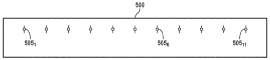
Fig. 5 is a two-dimensional array of radiators forming an RF lens according to an exemplary embodiment of the present invention.
Fig. 6A is a simplified block diagram of a radiator disposed in an RF lens, according to an exemplary embodiment of the present invention.
Fig. 6B is a simplified block diagram of a radiator disposed in an RF lens according to another exemplary embodiment of the present invention.
Fig. 7 shows some electronic components of a device adapted to be wirelessly charged according to an exemplary embodiment of the present invention.
Fig. 8 is a schematic diagram of an RF lens for wirelessly charging a device in accordance with an exemplary embodiment of the present invention.
Fig. 9 is a schematic diagram of an RF lens for simultaneously wirelessly charging a pair of devices, according to an exemplary embodiment of the present invention.
Fig. 10 is a schematic diagram of an RF lens simultaneously charging a pair of mobile and stationary devices, according to an exemplary embodiment of the present invention.
Fig. 11A illustrates a computer simulation of an electromagnetic field profile of a one-dimensional RF lens, according to an exemplary embodiment of the invention.
FIG. 11B is a simplified schematic diagram of an RF lens used to generate the electromagnetic field profile of FIG. 11A.
Fig. 12 shows that the variation in the computer simulated electromagnetic field profile generated by the RF lens of fig. 11B is a function of the spacing between each adjacent pair of radiators placed therein.
FIG. 13A is an exemplary computer simulated electromagnetic field profile for an RF lens and using a scale of-15 dB to 0dB, according to one exemplary embodiment of the present invention.
FIG. 13B shows the computer simulated electromagnetic field profile of FIG. 13A using a-45 dB to 0dB scale.
FIG. 14A is an exemplary computer simulated electromagnetic field profile for the RF lens of FIG. 13A and using a scale of-15 dB to 0dB, according to an exemplary embodiment of the present invention.
FIG. 14B illustrates the computer simulated electromagnetic field profile of FIG. 14A using a-45 dB to 0dB scale in accordance with an exemplary embodiment of the present invention.
FIG. 15A is an exemplary computer simulated electromagnetic field profile for an RF lens and using a scale of-15 dB to 0dB, according to one exemplary embodiment of the present invention.
FIG. 15B illustrates the computer simulated electromagnetic field profile of FIG. 15A using a-45 dB to 0dB scale in accordance with an exemplary embodiment of the present invention.
FIG. 16A is an exemplary computer simulated electromagnetic field profile of the RF lens of FIG. 15A using a scale of-15 dB to 0dB, according to an exemplary embodiment of the present invention.
FIG. 16B is a computer simulated electromagnetic field profile of FIG. 16A using a-45 dB to 0dB scale in accordance with an exemplary embodiment of the present invention.
Fig. 17A shows an exemplary radiator tile in which four radiators are placed, according to an exemplary embodiment of the present invention.
Fig. 17B illustrates an RF lens formed using the large number of radiator tiles of fig. 17A, according to an exemplary embodiment of the present invention.
Fig. 18 is a simplified block diagram of a radiator disposed in an RF lens according to another exemplary embodiment of the present invention.
Fig. 19 shows some electronic components placed in a device adapted to be wirelessly charged according to another exemplary embodiment of the present invention.
Fig. 20 shows an RF lens of a tracking device using a signal transmitted by the device according to another exemplary embodiment of the present invention.
Fig. 21 illustrates the transfer of power to an RF lens of a device in the presence of a large number of scattering objects, according to another exemplary embodiment of the present invention.
Fig. 22A illustrates an RF lens formed using a large number of radiators arranged in a circle, according to one embodiment of the present invention.
Fig. 22B illustrates an RF lens formed using a large number of radiators arranged in an elliptical shape, according to one embodiment of the present invention.
Detailed Description
An RF lens according to one embodiment of the invention includes a number of radiators adapted to transmit radio frequency electromagnetic EM waves (hereinafter alternatively referred to as EM waves or waves) whose phase and amplitude are modulated to concentrate the radiated power in a small volume of space (hereinafter alternatively referred to as a focus point or target area) in order to power electronic devices located in that space. Thus, the waves emitted by the radiators are caused to constructively interfere at the point of convergence. Although the description provided below refers to wireless power transmission, the following embodiments of the invention may be used to wirelessly transmit any other type of information.
Fig. 1 shows a number of radiators forming RF lenses arranged in an array 100, according to one embodiment of the invention. The array 100 is shown to include N radiators 101、102、103…10N-1、10NEach adapted to radiate an EM wave, the amplitude and phase of which may be independently controlled so as to cause constructive interference of the radiated EM waves at a point of focus at which a device to be charged is located, wherein N is an integer greater than 1. Fig. 2 shows a schematic view of the radiator 10 when selectedi(i is an integer varying from 1 to N) such that constructive interference between the waves occurs in a vicinity 102 where the device being wirelessly charged is located, i.e., a side view of the array 100 at a point of convergence. Region 102 is shown positioned at about distance d from center 104 of array 1001To (3). Distance between array center and focal pointOff is alternatively referred to herein as focal length. Although the following description of the RF lens is provided as a reference to a one-or two-dimensional array of radiators, it is to be understood that the RF lens according to the present invention may have any other arrangement of radiators, such as the circular arrangement 1000 of radiators 202 shown in fig. 22A, or the elliptical arrangement 1010 of radiators 202 shown in fig. 22B.
As shown in fig. 2, it is assumed that each radiator 10iPositioned at a distance y from the center 104 of the array 100iTo (3). Suppose respectively by AiTheta and thetaiShown by a radiator 10iAmplitude and phase of the radiated wave. Further assume that the wavelength of the wave being radiated is represented by λ. In order for the waves radiated by the radiators to constructively interfere in region 102 (i.e., the desired focal point), at various phases θiAnd a distance yiSatisfies the following relationship:

since the phase of the RF signal can be accurately controlled, power radiated from multiple sources can be concentrated on a target area where a device to be wirelessly charged is located according to the present invention. In addition, dynamic phase control enables tracking of the device as it moves from its initial position. For example, as shown in FIG. 3, if the device is moved along the focal plane to be located a distance d from the center point 104 of the array2In order to ensure that the target area is also located at the distance d2The phase of the source may be adjusted according to the following relationship:

referring to fig. 4, if the device is moved to a different location away from the focal plane (e.g., to a different point along the y-axis), the phase of the radiators can be dynamically adjusted as described below in order to track and maintain the target area focused on the device. Parameter ycY vector representing the new position of the device from the focal plane of the array: (I.e., a plane perpendicular to the y-axis and passing through the center 104 of the array 100), as shown in fig. 4.

The amount of power transmitted, i.e. (af/a), is defined by the wavelength λ of the wave to be radiated by the radiator, the array span or array aperture a shown in fig. 1, and the focal length.
In one embodiment, the distance between each pair of radiators is of the order of the wavelength of the signal being radiated. For example, if the frequency of the radiated wave is 2.4GHz (i.e., the wavelength is 12.5cm), the distance between each two radiators may be several tenths to several tens of wavelengths, which may vary depending on the application.
The RF lens according to the present invention operates to transmit power wirelessly in both near and far field regions. In the optical domain, the near field region is called the fresnel region and is defined as the region where the focal length is of the order of the aperture size. In the optical domain, the far field region is called the Fraunhofer region and is defined as one in which the focal length (F) is substantially greater than (2A)2Lambda)/lambda).
For wireless transmission of power to a device, according to the invention, the radiator phase is selected so as to take into account the difference in distance between the target point and the radiator. For example, assume focal length d in FIG. 21On the order of the aperture size a. Thus, due to the distance S1、S2、S3…SNDifferent from each other, so that the radiator 10 is changed1、102、103…10NCorresponding phase theta of1、θ2、θ3…θNSo as to satisfy expression (1) described above. The size of the focal spot of this type of region (approximately λ F/a) is relatively small due to the diffraction limited length.
The radiator array according to the invention is also operative for wireless transmission of power to a medium where the focal length is greater than (2A)2Lambda) to the target device in the far field region. For this type of region, it is assumed that the distances from the different array elements to the focused spot are the same. Therefore, the temperature of the molten metal is controlled,for this class of region, S1=S2=S3.....=SNAnd theta1=θ2=θ3…=θN. The size of the focal point of this type of zone is relatively large and therefore more suitable for wireless charging of larger instruments.
Fig. 5 shows an RF lens 200 according to another embodiment of the invention. The RF lens 200 is shown to include a two-dimensional array of radiators 202 arranged along rows and columnsi,j. Although the RF lens 200 is shown to include 121 radiators 202 disposed along 11 rows and 11 columnsi,j(integers i and j are subscripts varying from 1 to 11), but it is understood that an RF lens according to an embodiment of the present invention may have any number of radiators placed along U rows and V columns, where U and V are integers greater than 1. In the following description, the radiator 202i,jCollectively or individually, may be referred to as a radiator 202.
As described further below, the array radiator is locked to a reference frequency, which may be a sub-harmonic ( n 1,2, 3.) of the radiation frequency, or at the same frequency as the radiation frequency. The phases of the waves radiated by each radiator are independently controlled to enable the radiated waves to constructively interfere and concentrate their power on a target area within any region in space.
Fig. 6A is a simplified block diagram of a radiator 202 disposed in an RF lens 200, according to one embodiment of the present invention. As shown, the radiator 202 is shown to include, in part, a programmable delay element (also referred to herein as a phase modulator) 210, a phase/frequency locked loop 212, a power amplifier 214, and an antenna 216. The programmable delay element 210 is adapted to adapt the signal W2Delayed to generate a signal W3. Determining the signal W from the control signal Ctrl applied to the delay element2And W3The delay between them. In one embodiment, PLL/PLL 212 receives signal W1And has a frequency FrefTo generate the signal W2The frequency of which is locked to a reference frequency Fref. In another embodiment, signal W is generated by PLL/PLL 2122May have a plurality of reference frequencies FrefA defined frequency. Signal W3Amplified by a power amplifier 214 and transmitted by an antenna 216. Thus and as described above, the phase of the signal radiated by each radiator 202 can be changed by an associated programmable delay element 210 placed in the radiator.
Fig. 6B is a simplified block diagram of a radiator 202 disposed in an RF lens 200, according to another embodiment of the present invention. As shown, the radiator 202 is shown to include, in part, a programmable delay element 210, a phase/frequency locked loop 212, a power amplifier 214, and an antenna 216. The programmable delay element 210 is adapted to adapt the reference signal FrefDelayed to generate a delayed reference clock signal Fref_Delay. The signal F is determined from the control signal Ctrl applied to the delay element 210refAnd Fref_DelayThe delay between them. Signal W generated by phase/frequency locked loop 2122May have a frequency that is locked to the signal Fref_DelayFrequency or signal Fref_DelayA plurality of frequencies. In one embodiment (not shown), the delay element is disposed in and is part of phase-locked loop/frequency-locked loop 212. In another embodiment (not shown), the radiator may not have an amplifier.
Fig. 7 illustrates some components of a device 300 adapted for wireless charging, according to an embodiment of the invention. Device 300 is shown to include, in part, an antenna 302, a rectifier 304, and a regulator 306. The antenna 302 receives electromagnetic waves radiated by a radiator according to the present invention. The rectifier 304 is adapted to convert the received AC power to DC power. The regulator 306 is adapted to regulate the voltage signal received from the rectifier 304 and apply the regulated voltage to the device. In one embodiment, high power transfer efficiency is obtained if the aperture area of the receiver antenna is comparable to the size of the target area of the electromagnetic field. Such a receiver antenna is therefore optimized to ensure that most of the radiated power is used to charge the device, since most of the radiated power is concentrated in the small volume forming the target zone. In one embodiment, the device may be externally retrofitted with components required for wireless charging. In another embodiment, existing circuitry present in the charging device, such as an antenna, receiver, etc., may be used to utilize the power.
Fig. 8 is a schematic diagram of an RF lens 200 for wirelessly charging a device 300. In some embodiments, RF lens 200 wirelessly charges multiple devices simultaneously. Fig. 9 shows RF lens 200 simultaneously charging device 310 and 315 using focused waves of similar or different force. Fig. 10 shows that the RF lens 200 wirelessly charges the mobile devices 320, 325 and the stationary device 330, which are assumed to be indoors.
Fig. 11A shows a computer simulated magnetic field profile generated by a one-dimensional RF lens at 2 meters from an RF lens with an array of 11 isotropic radiators. The beam profiles were generated for three different frequencies, namely 200MHz (wavelength 150cm), 800MHz (wavelength 37.5cm) and 2400MHz (wavelength 12.50 cm). Since the distance between each pair of adjacent radiators of the RF lens is assumed to be 20cm, the RF lens has an aperture of 2 m. Thus, the wavelength is of the order of the aperture size and focal length of the radiator. FIG. 11B shows 11 radiators 505 spaced 20cm apartkIs shown in simplified schematic diagram of RF lens 500, where K is an integer varying from 1 to 11.
As seen from these profiles, for larger wavelengths having a frequency of 200MHz (i.e., plots 510, 515), the difference between profiles 510 and 515 is relatively ignored since the path difference from individual radiators to the convergence point is not essentially different. However, for each of the 800MHz and 2400MHz frequencies, the relative phase of the various radiators is selected whenPosition to consider from the radiation body 505kThe EM confinement (focusing) is much larger when the paths to the convergence point are different than when the radiator phases are set equal to each other. Although the above examples are provided with reference to operating frequencies of 200MHz, 800MHz, and 2400MHz, it is to be understood that embodiments of the present invention may be used for any other operating frequency, such as 5.8GHz, 10GHz, and 24 GHz.
Fig. 12 shows that the variation of the computer-simulated magnetic field profile generated by the RF lens 500 at a distance of 2 meters away from the RF lens is a function of the spacing between each adjacent pair of radiators. The RF lens is assumed to operate at 2400MHz frequency. Plots 610, 620, and 630 are plots of relative phase selection for various radiators to illustrate the phase shift from various radiators 505 according to expression (1) abovekComputer simulations of the field profile generated for radiator spacings of 5cm, 10cm and 20cm, respectively, after path difference to a point far from the RF lens 2. Plots 615, 625, and 635 are computer simulations of field profiles generated for radiator spacings of 5cm, 10cm, and 20cm, respectively, assuming that all the radiators placed in RF lens 500 have the same phase. As can be seen from these plots, as the distance between the radiators increases, resulting in a larger aperture size, the EM confinement also increases, resulting in a smaller focal point.
Fig. 13A is a computer simulation of an EM profile of an RF lens at a distance of 3 meters away from an RF lens in which a two-dimensional array of hertzian dipoles operating at a frequency of 900MHz, such as the RF lens 200 shown in fig. 5, is placed. The spacing between the dipole radiators is assumed to be 30 cm. The relative phase of the radiators is chosen to take into account the path difference from the radiator to the focal point assumed to be at a distance of 3 meters away from the RF lens. In other words, the relative phase of the radiators is selected to provide the RF lens with a focal length of about 3 meters. The scale used to generate fig. 13A is-15 dB to 0 dB. FIG. 13B shows the EM profile of FIG. 13A using a-45 dB to 0dB scale.
Fig. 14A is a computer simulation of the EM profile of the RF lens of fig. 13A/13B at a distance of 2 meters away from the focal point (i.e., 5 meters away from the RF lens). As shown from fig. 14A, the radiation power is dispersed over a larger area than those shown in fig. 13A and 13B. The scale used to generate fig. 14A is-15 dB to 0 dB. FIG. 14B shows the EM profile of FIG. 14A using a-45 dB to 0dB scale.
FIG. 15A is a computer simulation of the EM profile of an RF lens at a distance of 3 meters from the RF lens in which a two-dimensional array of Hertz dipoles operating at a frequency of 900MHz is placed. The spacing between the dipole radiators is assumed to be 30 cm. The relative phase of the radiators is chosen so as to take into account the path difference from the radiator to the focus assumed to be at a distance of 3 meters from the RF lens and at an offset of 1.5cm from the focal plane of the RF lens, i.e. the focal point has a y-coordinate of 1.5 meters from the focal plane (see fig. 4). The scale used to generate fig. 15A is-15 dB to 0 dB. FIG. 15B shows the EM profile of FIG. 15A using a-45 dB to 0dB scale.
Fig. 16A is a computer simulation of the EM profile of the RF lens of fig. 15A/15B at a distance of 2 meters away from the focal point (i.e., 5 meters away from the x-y plane of the RF lens). As shown from fig. 16A, the radiation power is dispersed over a larger area than that shown in fig. 15A. The scale used to generate fig. 16A is-15 dB to 0 dB. FIG. 16B shows the EM profile of FIG. 16A using a-45 dB to 0dB scale. The EM profile shown in fig. 13A, 13B, 14A, 14B, 15A, 15B, 16A, 16B illustrates the versatility of an RF lens according to the present invention in focusing power at any arbitrary point in 3D space.
According to one aspect of the invention, the size of the array forming the RF lens is configurable and can be changed by using radiator tiles, each of which may include one or more radiators. Fig. 17A shows a case in which four radiators 15 are placed11、1512、1521And 1522The example of the radiator tile 700. Although the radiator tile 700 is shown as including four radiators, it is to be understood that the radiator tile may have fewer (e.g., one) or more (e.g., 6) than four radiators according to an aspect of the present invention. Fig. 17B shows the use of 7 radiator tiles (i.e., radiator tile 700)11、70012、70013、70021、70022、70031、70032) Formed initially and provided with two spokesShooting body tile 70023And 70033Each of the 7 radiator tiles is similar to the radiator tile 700 shown in fig. 17A. Although not shown, it is understood that each radiator tile includes electrical connections that essentially supply power to the radiator and deliver information from the radiator as necessary. In one embodiment, the radiator formed in the tile is similar to the radiator 202 shown in fig. 6A and 6B.
According to one aspect of the invention, the RF lens is adapted to track the position of the mobile device so that the charging process continues as the mobile device changes position. To achieve this, in one embodiment, a subset or all of the radiators forming the RF lens comprise receivers. The charged device further comprises a transmitter adapted to radiate a continuous signal during the tracking phase. The position of the charging device is tracked by detecting relative differences between the phases (travel times) of the signals by at least three different receivers formed on the RF lens.
Fig. 18 is a simplified block diagram of a radiator 902 disposed in an RF lens, such as RF lens 200 shown in fig. 5, according to an embodiment of the present invention. The radiator 902 is similar to the radiator 202 shown in fig. 6A and 6B, except that the radiator 902 has a receiver amplifier and phase recovery circuit 218 and a switch S1. During power transmission, switch S1An antenna 216 is coupled via node a to a power amplifier 214 placed in the transmit path. During tracking, switch S1Antenna 216 is coupled via node B to a receiver amplifier and phase recovery circuit 218 placed in the receive path to receive the signal transmitted by the device being charged.
Fig. 19 shows some components of a device 900 adapted for wireless charging, according to an embodiment of the invention. The device 900 is similar to the device 300 shown in fig. 7, except that the device 900 has a transmit amplifier 316 and a switch S2. During power transmission, switch S2Antenna 302 is coupled via node D to rectifier 304 placed in the receive path. During tracking, switch S2Coupling an antenna 302 to a transmit amplifier 3 via a node C16 to enable transmission of a signal that is then used by the RF lens to detect the position of the device 300. Fig. 20 shows tracking of the RF lens 200 of the device 900 by receiving a signal transmitted by the device 900.
According to another embodiment of the invention, a pulse-based measurement technique is used to track the position of the mobile device. To achieve this, one or more radiators forming an RF lens transmit pulses during the tracking phase. After receiving the pulse, the device being tracked sends a response which is received by the radiators placed in the array. The travel time of the pulse from the RF lens to the device being tracked, together with the travel time of the response pulse from the device being tracked to the RF lens, represents the location of the device being tracked. In the presence of scatterers, the position of the device can be tracked using such estimation algorithms as maximum likelihood or least squares, kalman filtering, combinations of these techniques, and the like. WiFi and GPS signals may also be used to determine and track the location of the device.
The presence of scattering objects, reflectors, and absorbers can affect the ability of the RF lens to effectively focus the beam on a device being wirelessly charged. For example, fig. 21 shows the delivery of power to the RF lens 950 of the device 300 in the presence of a large number of scattering objects 250. To minimize this type of effect, the amplitude and phase of the individual radiators of the array may be varied to increase power transfer efficiency. Any of a number of techniques may be used to vary the amplitude or phase of the individual radiators.
According to one such technique, to minimize the effects of scattering, a signal is sent through one or more radiators placed in the RF lens. The signal radiated from the RF lens is scattered by the scattering object and received by the radiator (see fig. 18). The backscattering algorithm is then used to construct the scattering behavior of the environment. This configuration may be performed periodically to account for any changes that may occur over time. According to another technique, a portion or the entire array of radiators can be used around the electron beam scan to construct the scattering behavior from the received waves. According to another technique, the device that is performing wireless charging is adapted to periodically send information to the radiator about the power it receives. The optimization algorithm then uses the received information to account for scattering in order to maximize power transfer efficiency.
In some embodiments, the amplitude/phase of the radiator or the orientation of the RF lens may be adjusted to take advantage of the scattering medium. This enables the scattering objects to have the appropriate phase, amplitude and polarization to be used as a secondary source of radiators that direct power to the device to increase power transfer efficiency.
The above embodiments of the present invention are illustrative and not restrictive. Embodiments of the present invention are not limited to the number of radiators placed in the RF lens, nor to the dimensions used to form the array of RF lenses. Embodiments of the present invention are not limited to the type of radiator, its operating frequency, and the like. Embodiments of the present invention are not limited to the type of device that may be wirelessly charged. Embodiments of the invention are not limited to the type of substrate, semiconductor, flex, or other manner in which the various components of the radiator may be formed. Other additions, subtractions or modifications are obvious in view of the present disclosure and are considered within the scope of the appended claims.
Claims (25)
1. A wireless device configured to be powered by electromagnetic waves radiated by a first plurality of radiators forming an RF lens, the wireless device comprising:
a receiver configured to receive the electromagnetic waves radiated by the first plurality of radiators;
a rectifier that rectifies the received power to a DC voltage; and
a regulator that regulates the DC voltage;
the wireless device is further configured to respond to the electromagnetic waves to enable tracking of a location of the wireless device by the plurality of radiators, wherein a phase of the electromagnetic waves received by the wireless device from each of the plurality of radiators is determined according to a distance between the wireless device and the radiator.
2. The wireless device according to claim 1, wherein the wireless device is externally provided with a means for receiving the electromagnetic wave.
3. The wireless device of claim 1, wherein a phase of the electromagnetic waves dynamically changes in response to movement of the wireless device.
4. The wireless device of claim 1, wherein each radiator of the first plurality of radiators comprises an associated phase-locked loop that is locked to the same reference signal.
5. The wireless device of claim 4, wherein each phase-locked loop is configured to change a phase of an electromagnetic wave radiated by an associated radiator of the phase-locked loop.
6. The wireless device of claim 4, wherein each phase-locked loop is configured to vary an amplitude of an electromagnetic wave radiated by an associated radiator of the phase-locked loop.
7. The wireless device of claim 4, wherein each phase-locked loop is configured to vary a frequency of an electromagnetic wave radiated by an associated radiator of the phase-locked loop.
8. The wireless device of claim 4, wherein each phase-locked loop is configured to change a polarity of electromagnetic waves radiated by an associated radiator of the phase-locked loop.
9. The wireless device of claim 1, wherein the RF lens is further adapted to power a second wireless device at the same time that the first wireless device is powered.
10. The wireless device of claim 1, wherein the wireless device and RF lens are placed indoors.
11. The wireless device of claim 1, wherein each radiator of the first plurality of radiators comprises a programmable delay element.
12. The wireless device of claim 1, wherein the first plurality of radiators form a one-dimensional radiator array.
13. The wireless device of claim 1, wherein the first plurality of radiators form a two-dimensional radiator array.
14. The wireless device of claim 1, wherein the first plurality of radiators forms a first tile adapted to be placed in proximity to a second tile comprising a second plurality of radiators, the first tile and the second tile being in electrical communication with each other and cooperating to radiate electromagnetic waves to power the wireless device.
15. The wireless device of claim 1, wherein a location of the wireless device is tracked according to an estimation algorithm.
16. The wireless device of claim 1, wherein the location of the wireless device is tracked in accordance with a propagation time of an electromagnetic wave radiated from the RF lens to the wireless device and a propagation time of a response signal emitted by the wireless device to the RF lens.
17. The wireless device of claim 1, wherein the location of the wireless device is tracked using a signal selected from the group consisting of WiFi and GPS signals.
18. The wireless device of claim 1, wherein the frequency of the electromagnetic waves radiated by the first plurality of radiators is selected from the group consisting of: 5.8HHz, 10GHz and 24 GHz.
19. The wireless device of claim 14, wherein the wavelengths of the electromagnetic waves radiated by the first and second pluralities of radiators are in the mm-band.
20. The wireless device of claim 4, wherein the phase of each phase-locked loop is further selected to enable electromagnetic waves to be scattered by an object to power the wireless device.
21. The wireless device of claim 1, wherein the RF lens further comprises a receiver configured to receive electromagnetic waves reflected by an object due to scattering.
22. The wireless device of claim 1, wherein the first plurality of radiators operate at substantially the same frequency.
23. The wireless device of claim 22, wherein a phase of an electromagnetic wave radiated by at least a first radiator of the first plurality of radiators is changed.
24. The wireless device of claim 1, wherein the wireless device periodically sends information to the RF lens about the power it receives.
25. The wireless device of claim 14, wherein the first plurality of radiators and the second plurality of radiators operate at substantially the same frequency.
Applications Claiming Priority (3)
| Application Number | Priority Date | Filing Date | Title |
|---|---|---|---|
| US201261724638P | 2012-11-09 | 2012-11-09 | |
| US61/724,638 | 2012-11-09 | ||
| CN201380069301.3A CN104885333B (en) | 2012-11-09 | 2013-11-12 | Smart RF Lensing: Efficient, Dynamic, and Mobile Wireless Power Transfer |
Related Parent Applications (1)
| Application Number | Title | Priority Date | Filing Date |
|---|---|---|---|
| CN201380069301.3A Division CN104885333B (en) | 2012-11-09 | 2013-11-12 | Smart RF Lensing: Efficient, Dynamic, and Mobile Wireless Power Transfer |
Publications (2)
| Publication Number | Publication Date |
|---|---|
| CN108390160A CN108390160A (en) | 2018-08-10 |
| CN108390160B true CN108390160B (en) | 2021-04-27 |
Family
ID=50685254
Family Applications (2)
| Application Number | Title | Priority Date | Filing Date |
|---|---|---|---|
| CN201380069301.3A Active CN104885333B (en) | 2012-11-09 | 2013-11-12 | Smart RF Lensing: Efficient, Dynamic, and Mobile Wireless Power Transfer |
| CN201810343399.1A Active CN108390160B (en) | 2012-11-09 | 2013-11-12 | Smart RF Lensing: Efficient, Dynamic and Mobile Wireless Power Transfer |
Family Applications Before (1)
| Application Number | Title | Priority Date | Filing Date |
|---|---|---|---|
| CN201380069301.3A Active CN104885333B (en) | 2012-11-09 | 2013-11-12 | Smart RF Lensing: Efficient, Dynamic, and Mobile Wireless Power Transfer |
Country Status (5)
| Country | Link |
|---|---|
| US (6) | US10367380B2 (en) |
| EP (1) | EP2917998B1 (en) |
| KR (1) | KR102225531B1 (en) |
| CN (2) | CN104885333B (en) |
| WO (1) | WO2014075103A1 (en) |
Families Citing this family (244)
| Publication number | Priority date | Publication date | Assignee | Title |
|---|---|---|---|---|
| US10223717B1 (en) | 2014-05-23 | 2019-03-05 | Energous Corporation | Systems and methods for payment-based authorization of wireless power transmission service |
| US9831718B2 (en) | 2013-07-25 | 2017-11-28 | Energous Corporation | TV with integrated wireless power transmitter |
| US10263432B1 (en) | 2013-06-25 | 2019-04-16 | Energous Corporation | Multi-mode transmitter with an antenna array for delivering wireless power and providing Wi-Fi access |
| US9876394B1 (en) | 2014-05-07 | 2018-01-23 | Energous Corporation | Boost-charger-boost system for enhanced power delivery |
| US10205239B1 (en) | 2014-05-07 | 2019-02-12 | Energous Corporation | Compact PIFA antenna |
| US9853692B1 (en) | 2014-05-23 | 2017-12-26 | Energous Corporation | Systems and methods for wireless power transmission |
| US10090886B1 (en) | 2014-07-14 | 2018-10-02 | Energous Corporation | System and method for enabling automatic charging schedules in a wireless power network to one or more devices |
| US10312715B2 (en) | 2015-09-16 | 2019-06-04 | Energous Corporation | Systems and methods for wireless power charging |
| US9859756B2 (en) | 2012-07-06 | 2018-01-02 | Energous Corporation | Transmittersand methods for adjusting wireless power transmission based on information from receivers |
| US10224758B2 (en) | 2013-05-10 | 2019-03-05 | Energous Corporation | Wireless powering of electronic devices with selective delivery range |
| US9966765B1 (en) | 2013-06-25 | 2018-05-08 | Energous Corporation | Multi-mode transmitter |
| US10063064B1 (en) | 2014-05-23 | 2018-08-28 | Energous Corporation | System and method for generating a power receiver identifier in a wireless power network |
| US9941747B2 (en) | 2014-07-14 | 2018-04-10 | Energous Corporation | System and method for manually selecting and deselecting devices to charge in a wireless power network |
| US9893555B1 (en) | 2013-10-10 | 2018-02-13 | Energous Corporation | Wireless charging of tools using a toolbox transmitter |
| US9824815B2 (en) | 2013-05-10 | 2017-11-21 | Energous Corporation | Wireless charging and powering of healthcare gadgets and sensors |
| US10243414B1 (en) | 2014-05-07 | 2019-03-26 | Energous Corporation | Wearable device with wireless power and payload receiver |
| US10148097B1 (en) | 2013-11-08 | 2018-12-04 | Energous Corporation | Systems and methods for using a predetermined number of communication channels of a wireless power transmitter to communicate with different wireless power receivers |
| US20140008993A1 (en) | 2012-07-06 | 2014-01-09 | DvineWave Inc. | Methodology for pocket-forming |
| US9954374B1 (en) | 2014-05-23 | 2018-04-24 | Energous Corporation | System and method for self-system analysis for detecting a fault in a wireless power transmission Network |
| US9438045B1 (en) | 2013-05-10 | 2016-09-06 | Energous Corporation | Methods and systems for maximum power point transfer in receivers |
| US20150326070A1 (en) | 2014-05-07 | 2015-11-12 | Energous Corporation | Methods and Systems for Maximum Power Point Transfer in Receivers |
| US9899873B2 (en) | 2014-05-23 | 2018-02-20 | Energous Corporation | System and method for generating a power receiver identifier in a wireless power network |
| US9853458B1 (en) | 2014-05-07 | 2017-12-26 | Energous Corporation | Systems and methods for device and power receiver pairing |
| US10211680B2 (en) | 2013-07-19 | 2019-02-19 | Energous Corporation | Method for 3 dimensional pocket-forming |
| US10992185B2 (en) | 2012-07-06 | 2021-04-27 | Energous Corporation | Systems and methods of using electromagnetic waves to wirelessly deliver power to game controllers |
| US10230266B1 (en) | 2014-02-06 | 2019-03-12 | Energous Corporation | Wireless power receivers that communicate status data indicating wireless power transmission effectiveness with a transmitter using a built-in communications component of a mobile device, and methods of use thereof |
| US10965164B2 (en) | 2012-07-06 | 2021-03-30 | Energous Corporation | Systems and methods of wirelessly delivering power to a receiver device |
| US9973021B2 (en) | 2012-07-06 | 2018-05-15 | Energous Corporation | Receivers for wireless power transmission |
| US10270261B2 (en) | 2015-09-16 | 2019-04-23 | Energous Corporation | Systems and methods of object detection in wireless power charging systems |
| US9252628B2 (en) | 2013-05-10 | 2016-02-02 | Energous Corporation | Laptop computer as a transmitter for wireless charging |
| US9887739B2 (en) | 2012-07-06 | 2018-02-06 | Energous Corporation | Systems and methods for wireless power transmission by comparing voltage levels associated with power waves transmitted by antennas of a plurality of antennas of a transmitter to determine appropriate phase adjustments for the power waves |
| US10211682B2 (en) | 2014-05-07 | 2019-02-19 | Energous Corporation | Systems and methods for controlling operation of a transmitter of a wireless power network based on user instructions received from an authenticated computing device powered or charged by a receiver of the wireless power network |
| US10128693B2 (en) | 2014-07-14 | 2018-11-13 | Energous Corporation | System and method for providing health safety in a wireless power transmission system |
| US9893768B2 (en) | 2012-07-06 | 2018-02-13 | Energous Corporation | Methodology for multiple pocket-forming |
| US10050462B1 (en) | 2013-08-06 | 2018-08-14 | Energous Corporation | Social power sharing for mobile devices based on pocket-forming |
| US10063105B2 (en) | 2013-07-11 | 2018-08-28 | Energous Corporation | Proximity transmitters for wireless power charging systems |
| US9893554B2 (en) | 2014-07-14 | 2018-02-13 | Energous Corporation | System and method for providing health safety in a wireless power transmission system |
| US9876648B2 (en) | 2014-08-21 | 2018-01-23 | Energous Corporation | System and method to control a wireless power transmission system by configuration of wireless power transmission control parameters |
| US9812890B1 (en) | 2013-07-11 | 2017-11-07 | Energous Corporation | Portable wireless charging pad |
| US10381880B2 (en) | 2014-07-21 | 2019-08-13 | Energous Corporation | Integrated antenna structure arrays for wireless power transmission |
| US10141791B2 (en) | 2014-05-07 | 2018-11-27 | Energous Corporation | Systems and methods for controlling communications during wireless transmission of power using application programming interfaces |
| US9368020B1 (en) | 2013-05-10 | 2016-06-14 | Energous Corporation | Off-premises alert system and method for wireless power receivers in a wireless power network |
| US10103582B2 (en) | 2012-07-06 | 2018-10-16 | Energous Corporation | Transmitters for wireless power transmission |
| US9912199B2 (en) | 2012-07-06 | 2018-03-06 | Energous Corporation | Receivers for wireless power transmission |
| US9900057B2 (en) | 2012-07-06 | 2018-02-20 | Energous Corporation | Systems and methods for assigning groups of antenas of a wireless power transmitter to different wireless power receivers, and determining effective phases to use for wirelessly transmitting power using the assigned groups of antennas |
| US9882427B2 (en) | 2013-05-10 | 2018-01-30 | Energous Corporation | Wireless power delivery using a base station to control operations of a plurality of wireless power transmitters |
| US10141768B2 (en) | 2013-06-03 | 2018-11-27 | Energous Corporation | Systems and methods for maximizing wireless power transfer efficiency by instructing a user to change a receiver device's position |
| US9906065B2 (en) | 2012-07-06 | 2018-02-27 | Energous Corporation | Systems and methods of transmitting power transmission waves based on signals received at first and second subsets of a transmitter's antenna array |
| US10199835B2 (en) | 2015-12-29 | 2019-02-05 | Energous Corporation | Radar motion detection using stepped frequency in wireless power transmission system |
| US9124125B2 (en) * | 2013-05-10 | 2015-09-01 | Energous Corporation | Wireless power transmission with selective range |
| US9843201B1 (en) | 2012-07-06 | 2017-12-12 | Energous Corporation | Wireless power transmitter that selects antenna sets for transmitting wireless power to a receiver based on location of the receiver, and methods of use thereof |
| US9991741B1 (en) | 2014-07-14 | 2018-06-05 | Energous Corporation | System for tracking and reporting status and usage information in a wireless power management system |
| US10992187B2 (en) | 2012-07-06 | 2021-04-27 | Energous Corporation | System and methods of using electromagnetic waves to wirelessly deliver power to electronic devices |
| US10008889B2 (en) | 2014-08-21 | 2018-06-26 | Energous Corporation | Method for automatically testing the operational status of a wireless power receiver in a wireless power transmission system |
| US9859757B1 (en) | 2013-07-25 | 2018-01-02 | Energous Corporation | Antenna tile arrangements in electronic device enclosures |
| US10291055B1 (en) | 2014-12-29 | 2019-05-14 | Energous Corporation | Systems and methods for controlling far-field wireless power transmission based on battery power levels of a receiving device |
| US10211674B1 (en) | 2013-06-12 | 2019-02-19 | Energous Corporation | Wireless charging using selected reflectors |
| US10256657B2 (en) | 2015-12-24 | 2019-04-09 | Energous Corporation | Antenna having coaxial structure for near field wireless power charging |
| US9871398B1 (en) | 2013-07-01 | 2018-01-16 | Energous Corporation | Hybrid charging method for wireless power transmission based on pocket-forming |
| US10124754B1 (en) | 2013-07-19 | 2018-11-13 | Energous Corporation | Wireless charging and powering of electronic sensors in a vehicle |
| US10193396B1 (en) | 2014-05-07 | 2019-01-29 | Energous Corporation | Cluster management of transmitters in a wireless power transmission system |
| US12057715B2 (en) | 2012-07-06 | 2024-08-06 | Energous Corporation | Systems and methods of wirelessly delivering power to a wireless-power receiver device in response to a change of orientation of the wireless-power receiver device |
| US9891669B2 (en) | 2014-08-21 | 2018-02-13 | Energous Corporation | Systems and methods for a configuration web service to provide configuration of a wireless power transmitter within a wireless power transmission system |
| US9838083B2 (en) | 2014-07-21 | 2017-12-05 | Energous Corporation | Systems and methods for communication with remote management systems |
| US9143000B2 (en) | 2012-07-06 | 2015-09-22 | Energous Corporation | Portable wireless charging pad |
| US9859797B1 (en) | 2014-05-07 | 2018-01-02 | Energous Corporation | Synchronous rectifier design for wireless power receiver |
| US9787103B1 (en) | 2013-08-06 | 2017-10-10 | Energous Corporation | Systems and methods for wirelessly delivering power to electronic devices that are unable to communicate with a transmitter |
| US9923386B1 (en) | 2012-07-06 | 2018-03-20 | Energous Corporation | Systems and methods for wireless power transmission by modifying a number of antenna elements used to transmit power waves to a receiver |
| US10199849B1 (en) | 2014-08-21 | 2019-02-05 | Energous Corporation | Method for automatically testing the operational status of a wireless power receiver in a wireless power transmission system |
| US9867062B1 (en) | 2014-07-21 | 2018-01-09 | Energous Corporation | System and methods for using a remote server to authorize a receiving device that has requested wireless power and to determine whether another receiving device should request wireless power in a wireless power transmission system |
| US9941754B2 (en) | 2012-07-06 | 2018-04-10 | Energous Corporation | Wireless power transmission with selective range |
| US10128699B2 (en) | 2014-07-14 | 2018-11-13 | Energous Corporation | Systems and methods of providing wireless power using receiver device sensor inputs |
| US9793758B2 (en) | 2014-05-23 | 2017-10-17 | Energous Corporation | Enhanced transmitter using frequency control for wireless power transmission |
| US10063106B2 (en) | 2014-05-23 | 2018-08-28 | Energous Corporation | System and method for a self-system analysis in a wireless power transmission network |
| US9843213B2 (en) | 2013-08-06 | 2017-12-12 | Energous Corporation | Social power sharing for mobile devices based on pocket-forming |
| US10218227B2 (en) | 2014-05-07 | 2019-02-26 | Energous Corporation | Compact PIFA antenna |
| US11502551B2 (en) | 2012-07-06 | 2022-11-15 | Energous Corporation | Wirelessly charging multiple wireless-power receivers using different subsets of an antenna array to focus energy at different locations |
| US10206185B2 (en) | 2013-05-10 | 2019-02-12 | Energous Corporation | System and methods for wireless power transmission to an electronic device in accordance with user-defined restrictions |
| US9882430B1 (en) | 2014-05-07 | 2018-01-30 | Energous Corporation | Cluster management of transmitters in a wireless power transmission system |
| US9847679B2 (en) | 2014-05-07 | 2017-12-19 | Energous Corporation | System and method for controlling communication between wireless power transmitter managers |
| US10291066B1 (en) | 2014-05-07 | 2019-05-14 | Energous Corporation | Power transmission control systems and methods |
| US9825674B1 (en) | 2014-05-23 | 2017-11-21 | Energous Corporation | Enhanced transmitter that selects configurations of antenna elements for performing wireless power transmission and receiving functions |
| US10075008B1 (en) | 2014-07-14 | 2018-09-11 | Energous Corporation | Systems and methods for manually adjusting when receiving electronic devices are scheduled to receive wirelessly delivered power from a wireless power transmitter in a wireless power network |
| US9887584B1 (en) | 2014-08-21 | 2018-02-06 | Energous Corporation | Systems and methods for a configuration web service to provide configuration of a wireless power transmitter within a wireless power transmission system |
| US10224982B1 (en) | 2013-07-11 | 2019-03-05 | Energous Corporation | Wireless power transmitters for transmitting wireless power and tracking whether wireless power receivers are within authorized locations |
| US9876379B1 (en) | 2013-07-11 | 2018-01-23 | Energous Corporation | Wireless charging and powering of electronic devices in a vehicle |
| US9806564B2 (en) | 2014-05-07 | 2017-10-31 | Energous Corporation | Integrated rectifier and boost converter for wireless power transmission |
| US10439448B2 (en) | 2014-08-21 | 2019-10-08 | Energous Corporation | Systems and methods for automatically testing the communication between wireless power transmitter and wireless power receiver |
| US9847677B1 (en) | 2013-10-10 | 2017-12-19 | Energous Corporation | Wireless charging and powering of healthcare gadgets and sensors |
| US10038337B1 (en) | 2013-09-16 | 2018-07-31 | Energous Corporation | Wireless power supply for rescue devices |
| US10090699B1 (en) | 2013-11-01 | 2018-10-02 | Energous Corporation | Wireless powered house |
| US9941707B1 (en) | 2013-07-19 | 2018-04-10 | Energous Corporation | Home base station for multiple room coverage with multiple transmitters |
| US9899861B1 (en) | 2013-10-10 | 2018-02-20 | Energous Corporation | Wireless charging methods and systems for game controllers, based on pocket-forming |
| US9948135B2 (en) | 2015-09-22 | 2018-04-17 | Energous Corporation | Systems and methods for identifying sensitive objects in a wireless charging transmission field |
| US9939864B1 (en) | 2014-08-21 | 2018-04-10 | Energous Corporation | System and method to control a wireless power transmission system by configuration of wireless power transmission control parameters |
| US10186913B2 (en) | 2012-07-06 | 2019-01-22 | Energous Corporation | System and methods for pocket-forming based on constructive and destructive interferences to power one or more wireless power receivers using a wireless power transmitter including a plurality of antennas |
| US11616520B2 (en) | 2012-11-09 | 2023-03-28 | California Institute Of Technology | RF receiver |
| US10090714B2 (en) | 2013-11-12 | 2018-10-02 | California Institute Of Technology | Wireless power transfer |
| US11843260B2 (en) | 2012-11-09 | 2023-12-12 | California Institute Of Technology | Generator unit for wireless power transfer |
| EP2917998B1 (en) | 2012-11-09 | 2024-09-04 | California Institute of Technology | Smart rf lensing: efficient, dynamic and mobile wireless power transfer |
| US9419443B2 (en) | 2013-05-10 | 2016-08-16 | Energous Corporation | Transducer sound arrangement for pocket-forming |
| US9866279B2 (en) | 2013-05-10 | 2018-01-09 | Energous Corporation | Systems and methods for selecting which power transmitter should deliver wireless power to a receiving device in a wireless power delivery network |
| US9538382B2 (en) | 2013-05-10 | 2017-01-03 | Energous Corporation | System and method for smart registration of wireless power receivers in a wireless power network |
| US9819230B2 (en) | 2014-05-07 | 2017-11-14 | Energous Corporation | Enhanced receiver for wireless power transmission |
| US9537357B2 (en) | 2013-05-10 | 2017-01-03 | Energous Corporation | Wireless sound charging methods and systems for game controllers, based on pocket-forming |
| US10103552B1 (en) | 2013-06-03 | 2018-10-16 | Energous Corporation | Protocols for authenticated wireless power transmission |
| US10003211B1 (en) | 2013-06-17 | 2018-06-19 | Energous Corporation | Battery life of portable electronic devices |
| US10021523B2 (en) | 2013-07-11 | 2018-07-10 | Energous Corporation | Proximity transmitters for wireless power charging systems |
| US9979440B1 (en) | 2013-07-25 | 2018-05-22 | Energous Corporation | Antenna tile arrangements configured to operate as one functional unit |
| KR102473074B1 (en) * | 2013-11-22 | 2022-11-30 | 캘리포니아 인스티튜트 오브 테크놀로지 | Generator unit for wireless power transfer |
| WO2015077726A1 (en) | 2013-11-22 | 2015-05-28 | California Institute Of Technology | Active cmos recovery units for wireless power transmission |
| US9935482B1 (en) | 2014-02-06 | 2018-04-03 | Energous Corporation | Wireless power transmitters that transmit at determined times based on power availability and consumption at a receiving mobile device |
| US10075017B2 (en) | 2014-02-06 | 2018-09-11 | Energous Corporation | External or internal wireless power receiver with spaced-apart antenna elements for charging or powering mobile devices using wirelessly delivered power |
| AU2014385258B2 (en) * | 2014-03-06 | 2017-04-06 | Halliburton Energy Services, Inc. | Downhole power and data transfer using resonators |
| US10158257B2 (en) | 2014-05-01 | 2018-12-18 | Energous Corporation | System and methods for using sound waves to wirelessly deliver power to electronic devices |
| US9966784B2 (en) | 2014-06-03 | 2018-05-08 | Energous Corporation | Systems and methods for extending battery life of portable electronic devices charged by sound |
| US9800172B1 (en) | 2014-05-07 | 2017-10-24 | Energous Corporation | Integrated rectifier and boost converter for boosting voltage received from wireless power transmission waves |
| US10153645B1 (en) | 2014-05-07 | 2018-12-11 | Energous Corporation | Systems and methods for designating a master power transmitter in a cluster of wireless power transmitters |
| US10170917B1 (en) | 2014-05-07 | 2019-01-01 | Energous Corporation | Systems and methods for managing and controlling a wireless power network by establishing time intervals during which receivers communicate with a transmitter |
| US10153653B1 (en) | 2014-05-07 | 2018-12-11 | Energous Corporation | Systems and methods for using application programming interfaces to control communications between a transmitter and a receiver |
| US9973008B1 (en) | 2014-05-07 | 2018-05-15 | Energous Corporation | Wireless power receiver with boost converters directly coupled to a storage element |
| US11128179B2 (en) | 2014-05-14 | 2021-09-21 | California Institute Of Technology | Large-scale space-based solar power station: power transmission using steerable beams |
| WO2015175839A1 (en) | 2014-05-14 | 2015-11-19 | California Institute Of Technology | Large-scale space-based solar power station: packaging, deployment and stabilization of lightweight structures |
| US9876536B1 (en) | 2014-05-23 | 2018-01-23 | Energous Corporation | Systems and methods for assigning groups of antennas to transmit wireless power to different wireless power receivers |
| EP3149777B1 (en) | 2014-06-02 | 2024-02-14 | California Institute of Technology | Large-scale space-based solar power station: efficient power generation tiles |
| US12021162B2 (en) | 2014-06-02 | 2024-06-25 | California Institute Of Technology | Ultralight photovoltaic power generation tiles |
| US10068703B1 (en) | 2014-07-21 | 2018-09-04 | Energous Corporation | Integrated miniature PIFA with artificial magnetic conductor metamaterials |
| US10116143B1 (en) | 2014-07-21 | 2018-10-30 | Energous Corporation | Integrated antenna arrays for wireless power transmission |
| US9871301B2 (en) | 2014-07-21 | 2018-01-16 | Energous Corporation | Integrated miniature PIFA with artificial magnetic conductor metamaterials |
| US10447092B2 (en) * | 2014-07-31 | 2019-10-15 | Ossia Inc. | Techniques for determining distance between radiating objects in multipath wireless power delivery environments |
| US9917477B1 (en) | 2014-08-21 | 2018-03-13 | Energous Corporation | Systems and methods for automatically testing the communication between power transmitter and wireless receiver |
| US9965009B1 (en) | 2014-08-21 | 2018-05-08 | Energous Corporation | Systems and methods for assigning a power receiver to individual power transmitters based on location of the power receiver |
| US10530190B2 (en) | 2014-10-31 | 2020-01-07 | Teslonix Inc. | Wireless energy transfer in a multipath environment |
| US10474852B2 (en) | 2014-10-31 | 2019-11-12 | Teslonix Inc. | Charging long-range radio frequency identification tags |
| US10256678B2 (en) | 2014-10-31 | 2019-04-09 | Teslonix Inc. | Wireless energy transfer using alignment of electromagnetic waves |
| WO2016067100A1 (en) * | 2014-10-31 | 2016-05-06 | Teslonix Inc. | Wireless energy transfer using alignment of electromagnetic waves |
| US10122415B2 (en) | 2014-12-27 | 2018-11-06 | Energous Corporation | Systems and methods for assigning a set of antennas of a wireless power transmitter to a wireless power receiver based on a location of the wireless power receiver |
| US9893535B2 (en) | 2015-02-13 | 2018-02-13 | Energous Corporation | Systems and methods for determining optimal charging positions to maximize efficiency of power received from wirelessly delivered sound wave energy |
| JP6715317B2 (en) | 2015-07-22 | 2020-07-01 | カリフォルニア インスティチュート オブ テクノロジー | Large area structure for compact packaging |
| US10992253B2 (en) | 2015-08-10 | 2021-04-27 | California Institute Of Technology | Compactable power generation arrays |
| EP3334655B1 (en) | 2015-08-10 | 2021-03-24 | California Institute of Technology | Systems and methods for performing shape estimation using sun sensors in large-scale space-based solar power stations |
| US12283828B2 (en) | 2015-09-15 | 2025-04-22 | Energous Corporation | Receiver devices configured to determine location within a transmission field |
| US10523033B2 (en) | 2015-09-15 | 2019-12-31 | Energous Corporation | Receiver devices configured to determine location within a transmission field |
| US9906275B2 (en) | 2015-09-15 | 2018-02-27 | Energous Corporation | Identifying receivers in a wireless charging transmission field |
| US10199850B2 (en) | 2015-09-16 | 2019-02-05 | Energous Corporation | Systems and methods for wirelessly transmitting power from a transmitter to a receiver by determining refined locations of the receiver in a segmented transmission field associated with the transmitter |
| US10158259B1 (en) | 2015-09-16 | 2018-12-18 | Energous Corporation | Systems and methods for identifying receivers in a transmission field by transmitting exploratory power waves towards different segments of a transmission field |
| US11710321B2 (en) | 2015-09-16 | 2023-07-25 | Energous Corporation | Systems and methods of object detection in wireless power charging systems |
| US9893538B1 (en) | 2015-09-16 | 2018-02-13 | Energous Corporation | Systems and methods of object detection in wireless power charging systems |
| US10778041B2 (en) | 2015-09-16 | 2020-09-15 | Energous Corporation | Systems and methods for generating power waves in a wireless power transmission system |
| US9871387B1 (en) | 2015-09-16 | 2018-01-16 | Energous Corporation | Systems and methods of object detection using one or more video cameras in wireless power charging systems |
| US10186893B2 (en) | 2015-09-16 | 2019-01-22 | Energous Corporation | Systems and methods for real time or near real time wireless communications between a wireless power transmitter and a wireless power receiver |
| US9941752B2 (en) | 2015-09-16 | 2018-04-10 | Energous Corporation | Systems and methods of object detection in wireless power charging systems |
| US10008875B1 (en) | 2015-09-16 | 2018-06-26 | Energous Corporation | Wireless power transmitter configured to transmit power waves to a predicted location of a moving wireless power receiver |
| US10211685B2 (en) | 2015-09-16 | 2019-02-19 | Energous Corporation | Systems and methods for real or near real time wireless communications between a wireless power transmitter and a wireless power receiver |
| US10135294B1 (en) | 2015-09-22 | 2018-11-20 | Energous Corporation | Systems and methods for preconfiguring transmission devices for power wave transmissions based on location data of one or more receivers |
| US10033222B1 (en) | 2015-09-22 | 2018-07-24 | Energous Corporation | Systems and methods for determining and generating a waveform for wireless power transmission waves |
| US10027168B2 (en) | 2015-09-22 | 2018-07-17 | Energous Corporation | Systems and methods for generating and transmitting wireless power transmission waves using antennas having a spacing that is selected by the transmitter |
| US10050470B1 (en) | 2015-09-22 | 2018-08-14 | Energous Corporation | Wireless power transmission device having antennas oriented in three dimensions |
| US10153660B1 (en) | 2015-09-22 | 2018-12-11 | Energous Corporation | Systems and methods for preconfiguring sensor data for wireless charging systems |
| US10135295B2 (en) | 2015-09-22 | 2018-11-20 | Energous Corporation | Systems and methods for nullifying energy levels for wireless power transmission waves |
| FI3353793T3 (en) | 2015-09-22 | 2025-12-03 | California Inst Of Techn | Rf receiver |
| US10020678B1 (en) | 2015-09-22 | 2018-07-10 | Energous Corporation | Systems and methods for selecting antennas to generate and transmit power transmission waves |
| US10128686B1 (en) | 2015-09-22 | 2018-11-13 | Energous Corporation | Systems and methods for identifying receiver locations using sensor technologies |
| US10333332B1 (en) | 2015-10-13 | 2019-06-25 | Energous Corporation | Cross-polarized dipole antenna |
| US10734717B2 (en) | 2015-10-13 | 2020-08-04 | Energous Corporation | 3D ceramic mold antenna |
| US9899744B1 (en) | 2015-10-28 | 2018-02-20 | Energous Corporation | Antenna for wireless charging systems |
| US9853485B2 (en) | 2015-10-28 | 2017-12-26 | Energous Corporation | Antenna for wireless charging systems |
| US10063108B1 (en) | 2015-11-02 | 2018-08-28 | Energous Corporation | Stamped three-dimensional antenna |
| US10027180B1 (en) | 2015-11-02 | 2018-07-17 | Energous Corporation | 3D triple linear antenna that acts as heat sink |
| US10135112B1 (en) | 2015-11-02 | 2018-11-20 | Energous Corporation | 3D antenna mount |
| US9866074B2 (en) | 2015-11-17 | 2018-01-09 | Ossia Inc. | Integrated circuits for transmitting wireless power, receiving wireless power, and/or communicating wirelessly |
| US20170155285A1 (en) * | 2015-11-30 | 2017-06-01 | Electronics And Telecommunications Research Institute | Open type resonance coil without dual loops having serial type in-phase direct power feeding method without dual loops |
| US10256677B2 (en) | 2016-12-12 | 2019-04-09 | Energous Corporation | Near-field RF charging pad with adaptive loading to efficiently charge an electronic device at any position on the pad |
| US11863001B2 (en) | 2015-12-24 | 2024-01-02 | Energous Corporation | Near-field antenna for wireless power transmission with antenna elements that follow meandering patterns |
| US10320446B2 (en) | 2015-12-24 | 2019-06-11 | Energous Corporation | Miniaturized highly-efficient designs for near-field power transfer system |
| US10141771B1 (en) | 2015-12-24 | 2018-11-27 | Energous Corporation | Near field transmitters with contact points for wireless power charging |
| US10027159B2 (en) | 2015-12-24 | 2018-07-17 | Energous Corporation | Antenna for transmitting wireless power signals |
| US10079515B2 (en) | 2016-12-12 | 2018-09-18 | Energous Corporation | Near-field RF charging pad with multi-band antenna element with adaptive loading to efficiently charge an electronic device at any position on the pad |
| WO2018111921A1 (en) * | 2016-12-12 | 2018-06-21 | Energous Corporation | Methods of selectively activating antenna zones of a near-field charging pad to maximize wireless power delivered |
| US10038332B1 (en) | 2015-12-24 | 2018-07-31 | Energous Corporation | Systems and methods of wireless power charging through multiple receiving devices |
| US10008886B2 (en) | 2015-12-29 | 2018-06-26 | Energous Corporation | Modular antennas with heat sinks in wireless power transmission systems |
| WO2017137838A1 (en) * | 2016-02-09 | 2017-08-17 | Teslonix Inc. | Improved wireless energy transfer using alignment of electromagnetic waves |
| US10148137B2 (en) * | 2016-03-03 | 2018-12-04 | uBeam Inc. | Beamforming for wireless power transfer |
| US10230271B2 (en) | 2016-03-03 | 2019-03-12 | uBeam Inc. | Beamforming for wireless power transfer |
| EP3444925B1 (en) * | 2016-03-31 | 2022-04-27 | Samsung Electronics Co., Ltd. | Wireless power transmission apparatus and control method therefor |
| US10959110B2 (en) | 2016-03-31 | 2021-03-23 | Commscope Technologies Llc | Lensed antennas for use in wireless communications systems |
| US10797504B2 (en) * | 2016-05-19 | 2020-10-06 | Motorola Solutions, Inc. | System, method and device for wireless power transfer |
| US10923954B2 (en) | 2016-11-03 | 2021-02-16 | Energous Corporation | Wireless power receiver with a synchronous rectifier |
| RU2643177C1 (en) | 2016-12-14 | 2018-01-31 | Самсунг Электроникс Ко., Лтд. | Microwave wireless charger device with focusing of microwave field |
| CN106532984B (en) * | 2016-12-28 | 2019-07-02 | 王策 | A method and device for electromagnetic wave wireless charging or power supply for locking moving target |
| US10389161B2 (en) | 2017-03-15 | 2019-08-20 | Energous Corporation | Surface mount dielectric antennas for wireless power transmitters |
| US10439442B2 (en) | 2017-01-24 | 2019-10-08 | Energous Corporation | Microstrip antennas for wireless power transmitters |
| US10680319B2 (en) | 2017-01-06 | 2020-06-09 | Energous Corporation | Devices and methods for reducing mutual coupling effects in wireless power transmission systems |
| WO2018183892A1 (en) | 2017-03-30 | 2018-10-04 | Energous Corporation | Flat antennas having two or more resonant frequencies for use in wireless power transmission systems |
| KR20180117394A (en) * | 2017-04-19 | 2018-10-29 | 재단법인 다차원 스마트 아이티 융합시스템 연구단 | Wireless charging system for using frequency control |
| US10958108B2 (en) * | 2017-05-03 | 2021-03-23 | Searete Llc | Wireless power transfer management |
| US10511097B2 (en) | 2017-05-12 | 2019-12-17 | Energous Corporation | Near-field antennas for accumulating energy at a near-field distance with minimal far-field gain |
| US12074460B2 (en) | 2017-05-16 | 2024-08-27 | Wireless Electrical Grid Lan, Wigl Inc. | Rechargeable wireless power bank and method of using |
| US11462949B2 (en) | 2017-05-16 | 2022-10-04 | Wireless electrical Grid LAN, WiGL Inc | Wireless charging method and system |
| US12074452B2 (en) | 2017-05-16 | 2024-08-27 | Wireless Electrical Grid Lan, Wigl Inc. | Networked wireless charging system |
| US10720797B2 (en) | 2017-05-26 | 2020-07-21 | California Institute Of Technology | Method and apparatus for dynamic RF lens focusing and tracking of wireless power recovery unit |
| US10283952B2 (en) | 2017-06-22 | 2019-05-07 | Bretford Manufacturing, Inc. | Rapidly deployable floor power system |
| US10848853B2 (en) | 2017-06-23 | 2020-11-24 | Energous Corporation | Systems, methods, and devices for utilizing a wire of a sound-producing device as an antenna for receipt of wirelessly delivered power |
| US10714830B2 (en) * | 2017-10-03 | 2020-07-14 | Hughes Network Systems, Llc | Digital phase shifter switch and transmission line reduction |
| US10122219B1 (en) | 2017-10-10 | 2018-11-06 | Energous Corporation | Systems, methods, and devices for using a battery as a antenna for receiving wirelessly delivered power from radio frequency power waves |
| US11342798B2 (en) | 2017-10-30 | 2022-05-24 | Energous Corporation | Systems and methods for managing coexistence of wireless-power signals and data signals operating in a same frequency band |
| KR20200106076A (en) | 2018-01-10 | 2020-09-10 | 구루, 인크. | Method and apparatus for tracking wireless power supply |
| US10615647B2 (en) | 2018-02-02 | 2020-04-07 | Energous Corporation | Systems and methods for detecting wireless power receivers and other objects at a near-field charging pad |
| US11159057B2 (en) | 2018-03-14 | 2021-10-26 | Energous Corporation | Loop antennas with selectively-activated feeds to control propagation patterns of wireless power signals |
| JP6760322B2 (en) * | 2018-03-22 | 2020-09-23 | 株式会社豊田中央研究所 | Power transmission system |
| EP3776799A4 (en) * | 2018-03-27 | 2021-12-29 | Guru Wireless, Inc. | Situation aware wireless power transmission |
| JP7089060B2 (en) * | 2018-04-25 | 2022-06-21 | オッシア インコーポレイテッド | Directional wireless power and wireless data communication |
| US10796112B2 (en) | 2018-05-28 | 2020-10-06 | Teslonix Inc. | Protocol layer coordination of wireless energy transfer systems |
| US11515732B2 (en) * | 2018-06-25 | 2022-11-29 | Energous Corporation | Power wave transmission techniques to focus wirelessly delivered power at a receiving device |
| US11634240B2 (en) | 2018-07-17 | 2023-04-25 | California Institute Of Technology | Coilable thin-walled longerons and coilable structures implementing longerons and methods for their manufacture and coiling |
| US11772826B2 (en) | 2018-10-31 | 2023-10-03 | California Institute Of Technology | Actively controlled spacecraft deployment mechanism |
| US11437735B2 (en) | 2018-11-14 | 2022-09-06 | Energous Corporation | Systems for receiving electromagnetic energy using antennas that are minimally affected by the presence of the human body |
| WO2020106440A1 (en) | 2018-11-19 | 2020-05-28 | The Regents Of The University Of California | Systems and methods for battery-less wirelessly powered dielectric sensors |
| CN113196615A (en) * | 2018-12-12 | 2021-07-30 | 惠普发展公司,有限责任合伙企业 | Receiver and transmitter for wireless charging of devices in motion |
| WO2020160015A1 (en) | 2019-01-28 | 2020-08-06 | Energous Corporation | Systems and methods for miniaturized antenna for wireless power transmissions |
| US11018779B2 (en) | 2019-02-06 | 2021-05-25 | Energous Corporation | Systems and methods of estimating optimal phases to use for individual antennas in an antenna array |
| WO2020210449A1 (en) | 2019-04-09 | 2020-10-15 | Energous Corporation | Asymmetric spiral antennas for wireless power transmission and reception |
| US12266947B2 (en) | 2019-04-19 | 2025-04-01 | GuRu Wireless, Inc. | Adaptive roaming and articulating generating unit for wireless power transfer |
| WO2020215082A1 (en) * | 2019-04-19 | 2020-10-22 | Guru, Inc. | Adaptive roaming and articulating generating unit for wireless power transfer |
| WO2021055146A1 (en) * | 2019-09-18 | 2021-03-25 | The Regents Of The University Of California | Wirelessly powered stimulator |
| WO2021055898A1 (en) | 2019-09-20 | 2021-03-25 | Energous Corporation | Systems and methods for machine learning based foreign object detection for wireless power transmission |
| EP4032169A4 (en) | 2019-09-20 | 2023-12-06 | Energous Corporation | Classifying and detecting foreign objects using a power amplifier controller integrated circuit in wireless power transmission systems |
| US11411441B2 (en) | 2019-09-20 | 2022-08-09 | Energous Corporation | Systems and methods of protecting wireless power receivers using multiple rectifiers and establishing in-band communications using multiple rectifiers |
| WO2021055901A1 (en) | 2019-09-20 | 2021-03-25 | Energous Corporation | Asymmetric spiral antennas with parasitic elements for wireless power transmission |
| US11381118B2 (en) | 2019-09-20 | 2022-07-05 | Energous Corporation | Systems and methods for machine learning based foreign object detection for wireless power transmission |
| CN112787417A (en) * | 2019-11-04 | 2021-05-11 | 北京小米移动软件有限公司 | Wireless energy transmitting device, wireless energy receiving device, wireless energy supply method and system |
| US11355966B2 (en) | 2019-12-13 | 2022-06-07 | Energous Corporation | Charging pad with guiding contours to align an electronic device on the charging pad and efficiently transfer near-field radio-frequency energy to the electronic device |
| US10985617B1 (en) | 2019-12-31 | 2021-04-20 | Energous Corporation | System for wirelessly transmitting energy at a near-field distance without using beam-forming control |
| CN111262019B (en) * | 2020-01-17 | 2021-04-06 | 浙江大学 | A Two-Dimensional Fresnel Zone Plate Antenna Based on Plane Aperture Space Feeding |
| EP4110165A4 (en) | 2020-02-28 | 2024-05-15 | The Regents of the University of California | INTEGRATED ENERGY HARVESTING TRANSCEIVERS AND TRANSMITTERS WITH DUAL ANTENNA ARCHITECTURE FOR MINIATURIZED IMPLANTS AND ELECTROCHEMICAL SENSORS |
| US11799324B2 (en) | 2020-04-13 | 2023-10-24 | Energous Corporation | Wireless-power transmitting device for creating a uniform near-field charging area |
| US11469629B2 (en) | 2020-08-12 | 2022-10-11 | Energous Corporation | Systems and methods for secure wireless transmission of power using unidirectional communication signals from a wireless-power-receiving device |
| US12306285B2 (en) | 2020-12-01 | 2025-05-20 | Energous Corporation | Systems and methods for using one or more sensors to detect and classify objects in a keep-out zone of a wireless-power transmission field, and antennas with integrated sensor arrangements |
| IL282599B (en) | 2021-04-22 | 2022-02-01 | Wi Charge Ltd | Wireless power transmission system |
| WO2023022309A1 (en) * | 2021-08-18 | 2023-02-23 | 한국과학기술원 | Method for designing array antenna for increasing mid-range wireless power transmission efficiency |
| US11916398B2 (en) | 2021-12-29 | 2024-02-27 | Energous Corporation | Small form-factor devices with integrated and modular harvesting receivers, and shelving-mounted wireless-power transmitters for use therewith |
| US12142939B2 (en) | 2022-05-13 | 2024-11-12 | Energous Corporation | Integrated wireless-power-transmission platform designed to operate in multiple bands, and multi-band antennas for use therewith |
| US20240213808A1 (en) * | 2022-12-23 | 2024-06-27 | Ossia Inc. | Method and apparatus for providing high power in a wireless power system |
| WO2025014858A2 (en) * | 2023-07-11 | 2025-01-16 | Google Llc | Wireless power transfer to adaptive phase-changing devices |
Citations (3)
| Publication number | Priority date | Publication date | Assignee | Title |
|---|---|---|---|---|
| US6967462B1 (en) * | 2003-06-05 | 2005-11-22 | Nasa Glenn Research Center | Charging of devices by microwave power beaming |
| US7091852B2 (en) * | 2002-07-02 | 2006-08-15 | Tri-Sentinel, Inc. | Emergency response personnel automated accountability system |
| CN102640394A (en) * | 2009-11-30 | 2012-08-15 | 三星电子株式会社 | Wireless power transceiver and wireless power system |
Family Cites Families (125)
| Publication number | Priority date | Publication date | Assignee | Title |
|---|---|---|---|---|
| US1119732A (en) | 1907-05-04 | 1914-12-01 | Nikola Tesla | Apparatus for transmitting electrical energy. |
| GB2256948B (en) * | 1991-05-31 | 1995-01-25 | Thomas William Russell East | Self-focussing antenna array |
| AU4169497A (en) | 1996-08-29 | 1998-04-14 | David T. Borup | Apparatus and method for imaging with wavefields using inverse scattering techniques |
| US6208287B1 (en) | 1998-03-16 | 2001-03-27 | Raytheoncompany | Phased array antenna calibration system and method |
| US6127799A (en) | 1999-05-14 | 2000-10-03 | Gte Internetworking Incorporated | Method and apparatus for wireless powering and recharging |
| US7212414B2 (en) | 1999-06-21 | 2007-05-01 | Access Business Group International, Llc | Adaptive inductive power supply |
| US7522878B2 (en) | 1999-06-21 | 2009-04-21 | Access Business Group International Llc | Adaptive inductive power supply with communication |
| EP1734461A2 (en) | 1999-07-12 | 2006-12-20 | Matsushita Electric Industrial Co., Ltd. | Mobile body discrimination apparatus for rapidly acquiring respective data sets transmitted through modulation of reflected radio waves by transponders which are within a communication region of an interrogator apparatus |
| DE19958265A1 (en) | 1999-12-05 | 2001-06-21 | Iq Mobil Electronics Gmbh | Wireless energy transmission system with increased output voltage |
| US6184651B1 (en) | 2000-03-20 | 2001-02-06 | Motorola, Inc. | Contactless battery charger with wireless control link |
| TW479904U (en) | 2000-10-09 | 2002-03-11 | Sunplus Technology Co Ltd | Diode circuit to simulate zero cutoff voltage and the rectifying circuit having zero cutoff voltage characteristics |
| US7324785B2 (en) | 2001-01-11 | 2008-01-29 | Broadcom Corporation | Transmit power control of wireless communication devices |
| US7356952B2 (en) | 2002-06-17 | 2008-04-15 | Philip Morris Usa Inc. | System for coupling package displays to remote power source |
| US6970089B2 (en) | 2002-07-03 | 2005-11-29 | Battelle Memorial Institute K1-53 | Full-spectrum passive communication system and method |
| GB0229141D0 (en) * | 2002-12-16 | 2003-01-15 | Splashpower Ltd | Improvements relating to contact-less power transfer |
| US7580672B2 (en) * | 2003-06-27 | 2009-08-25 | Qualcomm Incorporated | Synthetic path diversity repeater |
| JP2007512796A (en) | 2003-10-17 | 2007-05-17 | ファイアフライ パワー テクノロジーズ,インコーポレイテッド | Method and apparatus for supplying power wirelessly |
| GB2414120B (en) | 2004-05-11 | 2008-04-02 | Splashpower Ltd | Controlling inductive power transfer systems |
| US7084811B1 (en) | 2004-09-14 | 2006-08-01 | Hrl Laboratories, Llc | Agile optical wavelength selection for antenna beamforming |
| WO2006039500A2 (en) * | 2004-09-29 | 2006-04-13 | California Institute Of Technology | Multi-element phased array transmitter with lo phase shifting and integrated power amplifier |
| EP1959825B1 (en) | 2005-10-24 | 2020-04-22 | Powercast Corporation | Method and apparatus for high efficiency rectification for various loads |
| JP5148504B2 (en) | 2005-12-09 | 2013-02-20 | テゴ,インコーポレイテッド | Multiple radio frequency network node RFID tag |
| US9130602B2 (en) | 2006-01-18 | 2015-09-08 | Qualcomm Incorporated | Method and apparatus for delivering energy to an electrical or electronic device via a wireless link |
| US8447234B2 (en) * | 2006-01-18 | 2013-05-21 | Qualcomm Incorporated | Method and system for powering an electronic device via a wireless link |
| US7952322B2 (en) * | 2006-01-31 | 2011-05-31 | Mojo Mobility, Inc. | Inductive power source and charging system |
| WO2008026080A2 (en) * | 2006-09-01 | 2008-03-06 | Bio Aim Technologies Holding Ltd. | Systems and methods for wireless power transfer |
| US8004235B2 (en) | 2006-09-29 | 2011-08-23 | Access Business Group International Llc | System and method for inductively charging a battery |
| JP4769684B2 (en) * | 2006-10-12 | 2011-09-07 | 株式会社デンソーアイティーラボラトリ | Electronic scanning radar equipment |
| JP4308855B2 (en) | 2007-01-17 | 2009-08-05 | セイコーエプソン株式会社 | Power reception control device, power reception device, and electronic device |
| US8827164B2 (en) | 2007-01-26 | 2014-09-09 | Lg Electronics Inc. | Contactless interface within a terminal to support a contactless service |
| US20080227478A1 (en) | 2007-03-15 | 2008-09-18 | Greene Charles E | Multiple frequency transmitter, receiver, and systems thereof |
| JP2008245404A (en) | 2007-03-27 | 2008-10-09 | Kddi Corp | Power transmission system |
| US8446248B2 (en) | 2007-06-14 | 2013-05-21 | Omnilectric, Inc. | Wireless power transmission system |
| US8159364B2 (en) * | 2007-06-14 | 2012-04-17 | Omnilectric, Inc. | Wireless power transmission system |
| US8619639B2 (en) | 2007-07-06 | 2013-12-31 | Lantiq Deutschland Gmbh | Power detector radio frequency multiplexer |
| JP2010541486A (en) | 2007-10-01 | 2010-12-24 | マックス リニアー、インコーポレイテッド | I/Q Calibration Technology |
| ES2361937T3 (en) | 2007-11-29 | 2011-06-24 | Nokia Siemens Networks Oy | RADIO CELL PERFORMANCE CONTROL AND / OR MONITORING BASED ON USER EQUIPMENT POSITIONING DATA AND RADIO QUALITY PARAMETER. |
| US8855554B2 (en) | 2008-03-05 | 2014-10-07 | Qualcomm Incorporated | Packaging and details of a wireless power device |
| PL2263296T3 (en) | 2008-04-03 | 2016-06-30 | Koninklijke Philips Nv | Wireless power transmission system |
| EP2281333A2 (en) | 2008-04-09 | 2011-02-09 | Intellon Corporation | Transmission line directional awareness |
| US8466654B2 (en) | 2008-07-08 | 2013-06-18 | Qualcomm Incorporated | Wireless high power transfer under regulatory constraints |
| US20100034238A1 (en) | 2008-08-05 | 2010-02-11 | Broadcom Corporation | Spread spectrum wireless resonant power delivery |
| US7893564B2 (en) | 2008-08-05 | 2011-02-22 | Broadcom Corporation | Phased array wireless resonant power delivery system |
| BRPI0822996A2 (en) | 2008-09-03 | 2015-06-23 | Thomson Licensing | Method and apparatus for wireless transmission power control |
| WO2010030767A1 (en) | 2008-09-11 | 2010-03-18 | The Board Of Trustees Of The University Of Alabama | System and method for three mode wireless enrgy harvesting |
| US8401595B2 (en) | 2008-12-08 | 2013-03-19 | Samsung Electronics Co., Ltd. | Method and system for integrated wireless power and data communication |
| US8497658B2 (en) | 2009-01-22 | 2013-07-30 | Qualcomm Incorporated | Adaptive power control for wireless charging of devices |
| US8223885B2 (en) | 2009-02-19 | 2012-07-17 | Research In Motion Limited | Mobile wireless communications device with separate In-phase (I) and Quadrature (Q) phase power amplification and power amplifier pre-distortion and IQ balance compensation |
| JP4752932B2 (en) * | 2009-02-25 | 2011-08-17 | 株式会社デンソー | Transmission device, reception device, and transmission / reception device |
| US8154402B2 (en) | 2009-03-12 | 2012-04-10 | Raytheon Company | Wireless temperature sensor network |
| CN101833839A (en) | 2009-03-13 | 2010-09-15 | 深圳富泰宏精密工业有限公司 | Multifunctional portable electronic device |
| US8338991B2 (en) | 2009-03-20 | 2012-12-25 | Qualcomm Incorporated | Adaptive impedance tuning in wireless power transmission |
| US8970180B2 (en) | 2009-04-07 | 2015-03-03 | Qualcomm Incorporated | Wireless power transmission scheduling |
| US8072380B2 (en) * | 2009-04-10 | 2011-12-06 | Raytheon Company | Wireless power transmission system and method |
| US8508422B2 (en) | 2009-06-09 | 2013-08-13 | Broadcom Corporation | Method and system for converting RF power to DC power utilizing a leaky wave antenna |
| US8853995B2 (en) | 2009-06-12 | 2014-10-07 | Qualcomm Incorporated | Devices for conveying wireless power and methods of operation thereof |
| US10325717B2 (en) | 2009-08-07 | 2019-06-18 | Auckland Uniservices Limited | Roadway powered electric vehicle system |
| US8374545B2 (en) | 2009-09-02 | 2013-02-12 | Qualcomm Incorporated | De-tuning in wireless power reception |
| US8415837B2 (en) | 2009-11-18 | 2013-04-09 | The Regents Of The University Of California | Switch mode voltage rectifier, RF energy conversion and wireless power supplies |
| US8390249B2 (en) | 2009-11-30 | 2013-03-05 | Broadcom Corporation | Battery with integrated wireless power receiver and/or RFID |
| US8879995B2 (en) | 2009-12-23 | 2014-11-04 | Viconics Electronics Inc. | Wireless power transmission using phased array antennae |
| US8686685B2 (en) * | 2009-12-25 | 2014-04-01 | Golba, Llc | Secure apparatus for wirelessly transferring power and communicating with one or more slave devices |
| US8421408B2 (en) * | 2010-01-23 | 2013-04-16 | Sotoudeh Hamedi-Hagh | Extended range wireless charging and powering system |
| WO2011091343A2 (en) | 2010-01-25 | 2011-07-28 | Access Business Group International Llc | Systems and methods for detecting data communication over a wireless power link |
| JP2011199975A (en) * | 2010-03-18 | 2011-10-06 | Nec Corp | Device, system and method for noncontact power transmission |
| GB201006904D0 (en) | 2010-04-26 | 2010-06-09 | Cambridge Entpr Ltd | RFID TAG location systems |
| KR101162857B1 (en) | 2010-06-04 | 2012-07-04 | 엘지이노텍 주식회사 | Transmitter and receiver for power transmission |
| KR101183525B1 (en) | 2010-06-11 | 2012-09-20 | 명지대학교 산학협력단 | Radio Frequency Energy Harvesting System and Method for Charging Battery of Mobile Devices |
| US8847577B2 (en) * | 2010-08-04 | 2014-09-30 | Sensus Spectrum Llc | Method and system of measuring current in an electric meter |
| KR101739283B1 (en) | 2010-08-31 | 2017-05-25 | 삼성전자주식회사 | Apparatus for adaptive resonant power transmission |
| US9173178B2 (en) * | 2010-09-21 | 2015-10-27 | Broadcom Corporation | Method and system for power headroom reporting in the presence of multiple transmit antennas |
| US9118217B2 (en) | 2010-09-30 | 2015-08-25 | Broadcom Corporation | Portable computing device with wireless power distribution |
| KR101796788B1 (en) | 2010-12-20 | 2017-11-10 | 엘지이노텍 주식회사 | Apparatus and method for trasmitting energy |
| JP5573628B2 (en) | 2010-11-22 | 2014-08-20 | 富士通株式会社 | Phase difference detection method, phase control method, phase difference detection circuit, phase control circuit, and wireless power transmission device |
| KR101672768B1 (en) | 2010-12-23 | 2016-11-04 | 삼성전자주식회사 | System for wireless power and data transmission and reception |
| TW201240462A (en) | 2011-03-18 | 2012-10-01 | Acer Inc | Electronic device and method for automatically searching a plurality of signal sources for substitute video content |
| TWI436620B (en) | 2011-03-31 | 2014-05-01 | Pegatron Corp | Portable electronic device and control method of the same |
| US10326309B2 (en) | 2011-05-13 | 2019-06-18 | Samsung Electronics Co., Ltd | Wireless power system comprising power transmitter and power receiver and method for receiving and transmitting power of the apparatuses |
| KR101322843B1 (en) | 2011-05-17 | 2013-10-28 | 삼성전자주식회사 | Method and apparatus for rx system for wireless power transmission using rx system |
| JP5753580B2 (en) * | 2011-06-01 | 2015-07-22 | 株式会社日立製作所 | Wireless transmitter, wireless receiver, wireless communication system, elevator control system, and substation control system |
| JP5718170B2 (en) | 2011-06-14 | 2015-05-13 | 株式会社ヨコオ | Electronic device and high-frequency rectifier charged without contact |
| US9030161B2 (en) * | 2011-06-27 | 2015-05-12 | Board Of Regents, The University Of Texas System | Wireless power transmission |
| JP3170470U (en) | 2011-07-07 | 2011-09-15 | 阪和電子工業株式会社 | Integrated value measurement circuit |
| US9252846B2 (en) | 2011-09-09 | 2016-02-02 | Qualcomm Incorporated | Systems and methods for detecting and identifying a wireless power device |
| KR20130035905A (en) | 2011-09-30 | 2013-04-09 | 삼성전자주식회사 | Method for wireless charging and apparatus for the same |
| US9264108B2 (en) | 2011-10-21 | 2016-02-16 | Qualcomm Incorporated | Wireless power carrier-synchronous communication |
| US9145110B2 (en) | 2011-10-27 | 2015-09-29 | Ford Global Technologies, Llc | Vehicle wireless charger safety system |
| SG190477A1 (en) | 2011-11-28 | 2013-06-28 | Sony Corp | Wireless energy transfer system |
| US9391463B2 (en) | 2011-12-22 | 2016-07-12 | Hanrim Postech Co., Ltd. | Device and method for wirelessly transmitting power |
| US8831528B2 (en) | 2012-01-04 | 2014-09-09 | Futurewei Technologies, Inc. | SAR control using capacitive sensor and transmission duty cycle control in a wireless device |
| US9144051B2 (en) | 2012-02-15 | 2015-09-22 | Microchip Technology Incorporated | Proximity detection using an antenna and directional coupler switch |
| KR101953913B1 (en) | 2012-04-02 | 2019-03-04 | 엘에스전선 주식회사 | Device and System for Wireless Power Transmission using Transmission Coil Array |
| US8830710B2 (en) | 2012-06-25 | 2014-09-09 | Eta Devices, Inc. | RF energy recovery system |
| US20140008993A1 (en) | 2012-07-06 | 2014-01-09 | DvineWave Inc. | Methodology for pocket-forming |
| US9124125B2 (en) * | 2013-05-10 | 2015-09-01 | Energous Corporation | Wireless power transmission with selective range |
| US9130397B2 (en) | 2013-05-10 | 2015-09-08 | Energous Corporation | Wireless charging and powering of electronic devices in a vehicle |
| KR101930805B1 (en) | 2012-07-10 | 2018-12-20 | 삼성전자주식회사 | Method and apparatus for wireless power reception |
| US9419476B2 (en) | 2012-07-10 | 2016-08-16 | Farrokh Mohamadi | Flat panel, stationary or mobile, spatially beam-formed wireless energy delivery system |
| US11843260B2 (en) | 2012-11-09 | 2023-12-12 | California Institute Of Technology | Generator unit for wireless power transfer |
| US11616520B2 (en) | 2012-11-09 | 2023-03-28 | California Institute Of Technology | RF receiver |
| US10090714B2 (en) | 2013-11-12 | 2018-10-02 | California Institute Of Technology | Wireless power transfer |
| EP2917998B1 (en) | 2012-11-09 | 2024-09-04 | California Institute of Technology | Smart rf lensing: efficient, dynamic and mobile wireless power transfer |
| WO2014075109A1 (en) | 2012-11-12 | 2014-05-15 | Parris Marcia Helena | Ear protector and ear protector wrap |
| RU2016151623A (en) | 2012-12-18 | 2018-11-15 | Нуклеас Сайнтифик Инк. | IDENTIFICATION OF A NONLINEAR SYSTEM FOR OPTIMIZATION OF WIRELESS ENERGY TRANSFER |
| US20140203768A1 (en) | 2013-01-18 | 2014-07-24 | Qualcomm Incorporated | Systems, methods, and apparatus related to inductive power transfer transmitter with sonic emitter |
| US10097051B2 (en) | 2013-02-27 | 2018-10-09 | National University Of Singapore | Rectenna circuit elements, circuits, and techniques for enhanced efficiency wireless power transmission or ambient RF energy harvesting |
| US9365126B2 (en) | 2013-05-10 | 2016-06-14 | Qualcomm Incorporated | System and method for detecting the presence of a moving object below a vehicle |
| US9601267B2 (en) | 2013-07-03 | 2017-03-21 | Qualcomm Incorporated | Wireless power transmitter with a plurality of magnetic oscillators |
| GB2517907B (en) | 2013-08-09 | 2018-04-11 | Drayson Tech Europe Ltd | RF Energy Harvester |
| WO2015077726A1 (en) | 2013-11-22 | 2015-05-28 | California Institute Of Technology | Active cmos recovery units for wireless power transmission |
| KR102473074B1 (en) | 2013-11-22 | 2022-11-30 | 캘리포니아 인스티튜트 오브 테크놀로지 | Generator unit for wireless power transfer |
| US9530038B2 (en) | 2013-11-25 | 2016-12-27 | Hand Held Products, Inc. | Indicia-reading system |
| CN103763720B (en) | 2014-01-03 | 2017-02-22 | 北京智谷睿拓技术服务有限公司 | Method and system for detecting obstacles influencing wireless energy transmission |
| US9772401B2 (en) | 2014-03-17 | 2017-09-26 | Qualcomm Incorporated | Systems, methods, and apparatus for radar-based detection of objects in a predetermined space |
| WO2015172049A1 (en) | 2014-05-09 | 2015-11-12 | The Board Of Trustees Of The Leland Stanford Junior University | Short range wireless communication |
| US9735605B2 (en) | 2014-06-17 | 2017-08-15 | Qualcomm Incorporated | Methods and systems for object detection and sensing for wireless charging systems |
| KR101640785B1 (en) | 2014-09-25 | 2016-07-19 | 국방과학연구소 | Wideband rectenna and rectifying apparatus for rectenna |
| US9985461B2 (en) | 2014-10-14 | 2018-05-29 | Ohio State Innovation Foundation | Systems capable of self-harvesting energy from wireless devices and methods of using the same |
| US10027354B2 (en) | 2015-03-25 | 2018-07-17 | Intel IP Corporation | Phased array weighting for power efficiency improvement with high peak-to-average power ratio signals |
| US20160380439A1 (en) | 2015-06-26 | 2016-12-29 | Lei Shao | Notification techniques for wireless power transfer systems |
| FI3353793T3 (en) | 2015-09-22 | 2025-12-03 | California Inst Of Techn | Rf receiver |
| US10033230B2 (en) | 2015-09-25 | 2018-07-24 | Intel Corporation | Controlling a wireless power transmitter based on human presence |
| US10720797B2 (en) | 2017-05-26 | 2020-07-21 | California Institute Of Technology | Method and apparatus for dynamic RF lens focusing and tracking of wireless power recovery unit |
| US11404915B2 (en) | 2017-11-21 | 2022-08-02 | Guru, Inc. | Wireless power transfer for consumer applications |
| US10615647B2 (en) | 2018-02-02 | 2020-04-07 | Energous Corporation | Systems and methods for detecting wireless power receivers and other objects at a near-field charging pad |
-
2013
- 2013-11-12 EP EP13854148.7A patent/EP2917998B1/en active Active
- 2013-11-12 US US14/078,489 patent/US10367380B2/en active Active
- 2013-11-12 CN CN201380069301.3A patent/CN104885333B/en active Active
- 2013-11-12 WO PCT/US2013/069757 patent/WO2014075103A1/en not_active Ceased
- 2013-11-12 KR KR1020157014646A patent/KR102225531B1/en active Active
- 2013-11-12 CN CN201810343399.1A patent/CN108390160B/en active Active
-
2014
- 2014-11-24 US US14/552,414 patent/US10320242B2/en active Active
-
2018
- 2018-03-30 US US15/942,211 patent/US11502552B2/en active Active
- 2018-04-12 US US15/952,124 patent/US11616401B2/en active Active
- 2018-04-12 US US15/952,128 patent/US11616402B2/en active Active
-
2022
- 2022-11-14 US US17/986,807 patent/US12322869B2/en active Active
Patent Citations (3)
| Publication number | Priority date | Publication date | Assignee | Title |
|---|---|---|---|---|
| US7091852B2 (en) * | 2002-07-02 | 2006-08-15 | Tri-Sentinel, Inc. | Emergency response personnel automated accountability system |
| US6967462B1 (en) * | 2003-06-05 | 2005-11-22 | Nasa Glenn Research Center | Charging of devices by microwave power beaming |
| CN102640394A (en) * | 2009-11-30 | 2012-08-15 | 三星电子株式会社 | Wireless power transceiver and wireless power system |
Also Published As
| Publication number | Publication date |
|---|---|
| CN104885333A (en) | 2015-09-02 |
| CN108390160A (en) | 2018-08-10 |
| CN104885333B (en) | 2018-05-15 |
| US11616402B2 (en) | 2023-03-28 |
| EP2917998A4 (en) | 2016-07-20 |
| US20180233964A1 (en) | 2018-08-16 |
| US10320242B2 (en) | 2019-06-11 |
| US20180233963A1 (en) | 2018-08-16 |
| US20180226841A1 (en) | 2018-08-09 |
| WO2014075103A1 (en) | 2014-05-15 |
| KR20150082450A (en) | 2015-07-15 |
| US20140175893A1 (en) | 2014-06-26 |
| US20230238713A1 (en) | 2023-07-27 |
| EP2917998B1 (en) | 2024-09-04 |
| US10367380B2 (en) | 2019-07-30 |
| US12322869B2 (en) | 2025-06-03 |
| KR102225531B1 (en) | 2021-03-08 |
| US20150130293A1 (en) | 2015-05-14 |
| US11502552B2 (en) | 2022-11-15 |
| US11616401B2 (en) | 2023-03-28 |
| EP2917998A1 (en) | 2015-09-16 |
Similar Documents
| Publication | Publication Date | Title |
|---|---|---|
| US12322869B2 (en) | Smart RF lensing: efficient, dynamic and mobile wireless power transfer | |
| US12283827B2 (en) | RF receiver | |
| EP3353793B1 (en) | Rf receiver | |
| Zhang et al. | Near-field wireless power transfer for 6G internet of everything mobile networks: Opportunities and challenges | |
| Khang et al. | Microwave power transfer with optimal number of rectenna arrays for midrange applications | |
| Han et al. | Adaptively smart wireless power transfer using 2-bit programmable metasurface | |
| EP3072214B1 (en) | Generator unit for wireless power transfer | |
| RU2658332C1 (en) | Wireless power transmission system for a multi-path environment | |
| US10211680B2 (en) | Method for 3 dimensional pocket-forming | |
| Li et al. | Design of retrodirective antenna arrays for short-range wireless power transmission | |
| Yang et al. | Auto-tracking wireless power transfer system with focused-beam phased array | |
| US20190097465A1 (en) | Wafer-Level Integrated Antenna Array For Wireless Battery Charging | |
| JP2024003082A (en) | Power transmission equipment, control method and control program | |
| Katbay et al. | Retrodirective wireless power transfer for short and long range applications | |
| US10658752B2 (en) | Antenna aperture expansion flaps | |
| Zhao et al. | Innovative RIS Prototyping Enhancing Wireless Communication with Real-Time Spot Beam Tracking and OAM Wavefront Manipulation | |
| JP2024002994A (en) | Power transmission device, wireless power transmission system, control method and control program |
Legal Events
| Date | Code | Title | Description |
|---|---|---|---|
| PB01 | Publication | ||
| PB01 | Publication | ||
| SE01 | Entry into force of request for substantive examination | ||
| SE01 | Entry into force of request for substantive examination | ||
| GR01 | Patent grant | ||
| GR01 | Patent grant |