CN108366630B - Component for an aerosol-generating system comprising a disabling member - Google Patents
Component for an aerosol-generating system comprising a disabling member Download PDFInfo
- Publication number
- CN108366630B CN108366630B CN201680073706.8A CN201680073706A CN108366630B CN 108366630 B CN108366630 B CN 108366630B CN 201680073706 A CN201680073706 A CN 201680073706A CN 108366630 B CN108366630 B CN 108366630B
- Authority
- CN
- China
- Prior art keywords
- aerosol
- component
- storage portion
- housing
- generating system
- Prior art date
- Legal status (The legal status is an assumption and is not a legal conclusion. Google has not performed a legal analysis and makes no representation as to the accuracy of the status listed.)
- Active
Links
Images


Classifications
-
- A—HUMAN NECESSITIES
- A24—TOBACCO; CIGARS; CIGARETTES; SIMULATED SMOKING DEVICES; SMOKERS' REQUISITES
- A24F—SMOKERS' REQUISITES; MATCH BOXES; SIMULATED SMOKING DEVICES
- A24F40/00—Electrically operated smoking devices; Component parts thereof; Manufacture thereof; Maintenance or testing thereof; Charging means specially adapted therefor
- A24F40/40—Constructional details, e.g. connection of cartridges and battery parts
- A24F40/48—Fluid transfer means, e.g. pumps
- A24F40/485—Valves; Apertures
-
- A—HUMAN NECESSITIES
- A24—TOBACCO; CIGARS; CIGARETTES; SIMULATED SMOKING DEVICES; SMOKERS' REQUISITES
- A24F—SMOKERS' REQUISITES; MATCH BOXES; SIMULATED SMOKING DEVICES
- A24F40/00—Electrically operated smoking devices; Component parts thereof; Manufacture thereof; Maintenance or testing thereof; Charging means specially adapted therefor
- A24F40/40—Constructional details, e.g. connection of cartridges and battery parts
- A24F40/42—Cartridges or containers for inhalable precursors
-
- A—HUMAN NECESSITIES
- A24—TOBACCO; CIGARS; CIGARETTES; SIMULATED SMOKING DEVICES; SMOKERS' REQUISITES
- A24F—SMOKERS' REQUISITES; MATCH BOXES; SIMULATED SMOKING DEVICES
- A24F40/00—Electrically operated smoking devices; Component parts thereof; Manufacture thereof; Maintenance or testing thereof; Charging means specially adapted therefor
- A24F40/40—Constructional details, e.g. connection of cartridges and battery parts
- A24F40/49—Child proofing
-
- B—PERFORMING OPERATIONS; TRANSPORTING
- B65—CONVEYING; PACKING; STORING; HANDLING THIN OR FILAMENTARY MATERIAL
- B65D—CONTAINERS FOR STORAGE OR TRANSPORT OF ARTICLES OR MATERIALS, e.g. BAGS, BARRELS, BOTTLES, BOXES, CANS, CARTONS, CRATES, DRUMS, JARS, TANKS, HOPPERS, FORWARDING CONTAINERS; ACCESSORIES, CLOSURES, OR FITTINGS THEREFOR; PACKAGING ELEMENTS; PACKAGES
- B65D25/00—Details of other kinds or types of rigid or semi-rigid containers
- B65D25/02—Internal fittings
- B65D25/04—Partitions
- B65D25/08—Partitions with provisions for removing or destroying, e.g. to facilitate mixing of contents
-
- B—PERFORMING OPERATIONS; TRANSPORTING
- B65—CONVEYING; PACKING; STORING; HANDLING THIN OR FILAMENTARY MATERIAL
- B65D—CONTAINERS FOR STORAGE OR TRANSPORT OF ARTICLES OR MATERIALS, e.g. BAGS, BARRELS, BOTTLES, BOXES, CANS, CARTONS, CRATES, DRUMS, JARS, TANKS, HOPPERS, FORWARDING CONTAINERS; ACCESSORIES, CLOSURES, OR FITTINGS THEREFOR; PACKAGING ELEMENTS; PACKAGES
- B65D49/00—Arrangements or devices for preventing refilling of containers
- B65D49/02—One-way valves
-
- H—ELECTRICITY
- H05—ELECTRIC TECHNIQUES NOT OTHERWISE PROVIDED FOR
- H05B—ELECTRIC HEATING; ELECTRIC LIGHT SOURCES NOT OTHERWISE PROVIDED FOR; CIRCUIT ARRANGEMENTS FOR ELECTRIC LIGHT SOURCES, IN GENERAL
- H05B3/00—Ohmic-resistance heating
- H05B3/0019—Circuit arrangements
-
- A—HUMAN NECESSITIES
- A24—TOBACCO; CIGARS; CIGARETTES; SIMULATED SMOKING DEVICES; SMOKERS' REQUISITES
- A24F—SMOKERS' REQUISITES; MATCH BOXES; SIMULATED SMOKING DEVICES
- A24F40/00—Electrically operated smoking devices; Component parts thereof; Manufacture thereof; Maintenance or testing thereof; Charging means specially adapted therefor
- A24F40/10—Devices using liquid inhalable precursors
-
- H—ELECTRICITY
- H05—ELECTRIC TECHNIQUES NOT OTHERWISE PROVIDED FOR
- H05B—ELECTRIC HEATING; ELECTRIC LIGHT SOURCES NOT OTHERWISE PROVIDED FOR; CIRCUIT ARRANGEMENTS FOR ELECTRIC LIGHT SOURCES, IN GENERAL
- H05B2203/00—Aspects relating to Ohmic resistive heating covered by group H05B3/00
- H05B2203/021—Heaters specially adapted for heating liquids
Landscapes
- Engineering & Computer Science (AREA)
- Mechanical Engineering (AREA)
- Health & Medical Sciences (AREA)
- Child & Adolescent Psychology (AREA)
- General Health & Medical Sciences (AREA)
- Containers And Packaging Bodies Having A Special Means To Remove Contents (AREA)
- Disinfection, Sterilisation Or Deodorisation Of Air (AREA)
- Respiratory Apparatuses And Protective Means (AREA)
- Nozzles (AREA)
Abstract
一种用于气溶胶生成系统的部件(100)、一种用于气溶胶生成系统的筒和一种气溶胶生成系统,其中所述部件(100)、所述筒和所述气溶胶生成系统包括:用于存储气溶胶形成基质(110)的存储部分(108);以及用于使得所述部件(100)、所述筒或所述气溶胶生成系统不可逆地不可操作的手动操作禁用构件。所述部件(100)、所述筒和所述气溶胶生成系统可进一步包括气溶胶生成构件和一个或多个空气通道(115)。所述禁用构件可被配置成使得所述存储部分(108)、所述气溶胶生成构件和所述一个或多个空气通道(115)中的至少一个不可逆地不可操作。
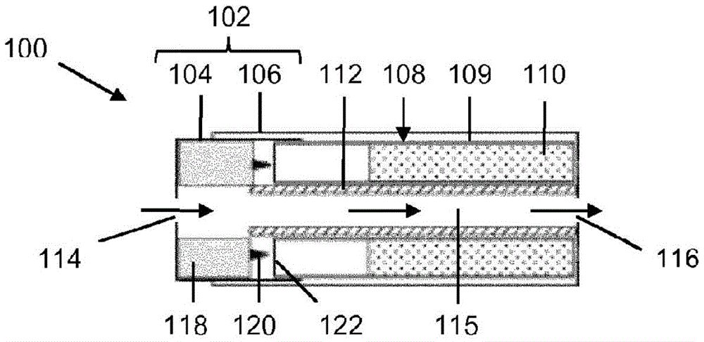
A component (100) for an aerosol-generating system, a cartridge for an aerosol-generating system, and an aerosol-generating system, wherein the component (100), the cartridge and the aerosol-generating system Comprising: a storage portion (108) for storing an aerosol-forming substrate (110); and a manual operation disabling member for rendering the component (100), the cartridge or the aerosol-generating system irreversibly inoperable. The component (100), the cartridge and the aerosol-generating system may further comprise aerosol-generating means and one or more air passages (115). The disabling member may be configured to render at least one of the storage portion (108), the aerosol-generating member and the one or more air passages (115) irreversibly inoperable.
Description
技术领域technical field
本发明涉及一种用于气溶胶生成系统的部件。具体来说,本发明涉及用于电操作式吸烟系统的部件。The invention relates to a component for an aerosol generating system. In particular, the invention relates to components for electrically operated smoking systems.
背景技术Background technique
一种类型的气溶胶生成系统是电操作式吸烟系统。电操作式吸烟系统通常使用被雾化以形成气溶胶的液态气溶胶形成基质。电操作式吸烟系统通常包括电源、用于保持液态气溶胶形成基质的供应的液体存储部分和雾化器。One type of aerosol generating system is an electrically operated smoking system. Electrically operated smoking systems typically use a liquid aerosol-forming substrate that is atomized to form an aerosol. Electrically operated smoking systems typically include a power source, a liquid storage portion for maintaining a supply of liquid aerosol-forming substrate, and a nebuliser.
已知提供具有禁用构件,例如熔线的电操作式吸烟系统,所述电操作式吸烟系统由电子控制器操作以使得系统或筒不可响应于特定操作条件操作。然而,此类禁用构件并不向使用者提供何时使得系统不可操作的选择。还已知提供具有暂时禁用构件,例如帽和可旋转阀的电操作式吸烟系统以在所述系统不在使用中时暂时阻塞系统的通道。然而,可移除此类暂时禁用构件以恢复所述吸烟系统的操作,并因此使得使用者并不能够使得系统或筒不可逆地不可操作。It is known to provide electrically operated smoking systems having disabling means, such as fusible links, which are operated by an electronic controller such that the system or cartridge cannot be operated in response to certain operating conditions. However, such disabling means do not provide the user with a choice of when to render the system inoperable. It is also known to provide electrically operated smoking systems with temporarily disabling members, such as caps and rotatable valves, to temporarily block access to the system when the system is not in use. However, such temporary disabling means may be removed to restore operation of the smoking system, and thus render the user unable to irreversibly render the system or cartridge inoperable.
期望的是提供气溶胶生成系统或用于气溶胶生成系统的部件,例如筒,其使使用者能够在使用者选择时使得气溶胶生成系统或用于气溶胶生成系统的部件不可逆地不可操作,从而大体上防止或禁止气溶胶生成系统的未经授权的使用。It is desirable to provide an aerosol generating system or a component for an aerosol generating system, such as a cartridge, which enables a user to render the aerosol generating system or a component for an aerosol generating system irreversibly inoperable at the user's option, Unauthorized use of the aerosol generating system is thereby substantially prevented or inhibited.
发明内容Contents of the invention
根据本发明的第一方面,提供有一种用于气溶胶生成系统的部件,所述部件包括:用于保存气溶胶形成基质的存储部分;以及用于使得所述部件不可逆地不可操作的手动操作禁用构件。According to a first aspect of the present invention there is provided a component for an aerosol generating system, the component comprising: a storage portion for holding an aerosol-forming substrate; and a manual operation for rendering the component irreversibly inoperable Disable widgets.
由于一些原因,能够手动操作禁用构件以使得所述部件不可逆地不可操作是有利的。所述手动操作禁用构件使使用者能够防止所述部件的未经授权的操作。所述手动操作禁用构件使使用者能够决定何时使得所述部件不可逆地不可操作。使用者可决定使得所述部件不可逆地不可操作以大体上防止或禁止通过不适当或甚至危害性基质材料对存储部分的填充或再填充。使用者可决定使得所述部件不可逆地不可操作以大体上防止或禁止对保存在存储部分中的气溶胶形成基质的未经授权的存取。使用者可决定使得所述部件不可逆地不可操作以大体上防止或禁止气溶胶生成系统的操作。使用者可决定使得所述部件不可逆地不可操作以大体上防止或禁止气溶胶生成系统中所述部件的操作。通过使得所述部件不可逆地不可操作,使用者可更为倾斜以安置所使用或非所需部件或气溶胶生成系统。Being able to manually operate the disabling member to render the component irreversibly inoperable is advantageous for a number of reasons. The manual operation disabling member enables a user to prevent unauthorized operation of the component. The manual operation disabling member enables a user to decide when to render the component irreversibly inoperable. A user may decide to render the component irreversibly inoperable to substantially prevent or inhibit filling or refilling of the storage portion by inappropriate or even hazardous matrix material. A user may decide to render the component irreversibly inoperable to substantially prevent or inhibit unauthorized access to the aerosol-forming substrate held in the storage portion. A user may decide to render the component irreversibly inoperable to substantially prevent or inhibit operation of the aerosol generating system. A user may decide to render the component irreversibly inoperable to substantially prevent or inhibit operation of the component in the aerosol generating system. By making the components irreversibly inoperable, the user can lean further to position used or undesired components or the aerosol generating system.
如本文中所使用,参考本发明,术语‘手动操作’用于描述由使用者操作的禁用构件。换句话说,所述禁用构件被配置成由使用者操作,而非由气溶胶生成系统的控制系统操作。As used herein, with reference to the present invention, the term 'manually operated' is used to describe a disabling member operated by a user. In other words, the disabling member is configured to be operated by a user rather than a control system of the aerosol generating system.
已经通过手动操作禁用构件使得不可逆地不可操作的部件是将不在气溶胶生成系统的部分中或作为气溶胶生成系统的部分操作的部件。已经通过禁用构件使得不可逆地不可操作的部件可未经改性以在气溶胶生成系统中操作而不会大体上更改或潜在地损害所述部件。换句话说,所述禁用构件可被配置成使得所述部件不可永久性地操作。Components that have been rendered irreversibly inoperable by manually disabling means are components that will not operate in or as part of the aerosol generating system. Components that have been rendered irreversibly inoperable by disabling means may be unmodified for operation in the aerosol generating system without substantially altering or potentially damaging the component. In other words, the disabling member may be configured such that the component is not permanently operable.
所述部件可以是用于气溶胶生成系统的筒的部分。所述部件可为用于气溶胶生成系统的筒。所述部件可为气溶胶生成系统的整体部分。所述部件可在气溶胶生成系统中一体成型。所述部件可固定到气溶胶生成系统的其它部件或部分。所述气溶胶生成系统可为电操作式吸烟系统。所述禁用构件可被配置成使得所述部件、所述筒、所述气溶胶生成系统或所述电操作式吸烟系统不可逆地不可操作。The component may be part of a cartridge for an aerosol generating system. The component may be a cartridge for an aerosol generating system. The component may be an integral part of the aerosol generating system. The components may be integrally formed in the aerosol generating system. The components may be secured to other components or parts of the aerosol generating system. The aerosol generating system may be an electrically operated smoking system. The disabling member may be configured to render the component, the cartridge, the aerosol generating system or the electrically operated smoking system irreversibly inoperable.
所述部件可包括额外特征。所述部件可包括气溶胶生成构件。所述部件可包括一个或多个空气通道。在所述部件包括气溶胶生成构件的情况下,所述气溶胶生成构件的至少一部分可布置在一个或多个空气通道中的一个或多个中。所述禁用构件可被配置成使得所述部件的任何特征不可逆地不可操作。所述禁用构件可被配置成使得所述部件的一个或多个特征不可逆地不可操作。所述禁用构件可被配置成使得所述存储部分不可逆地不可操作。所述禁用构件可被配置成使得所述气溶胶生成构件不可逆地不可操作。所述禁用构件可被配置成使得所述一个或多个空气通道不可逆地不可操作。The components may include additional features. The component may comprise an aerosol generating member. The component may include one or more air passages. Where the component comprises an aerosol generating member, at least a portion of the aerosol generating member may be arranged in one or more of the one or more air channels. The disabling member may be configured to render any feature of the component irreversibly inoperable. The disabling member may be configured to render one or more features of the component irreversibly inoperable. The disabling member may be configured to render the storage portion irreversibly inoperable. The disabling means may be configured to render the aerosol generating means irreversibly inoperable. The disabling member may be configured to render the one or more air passages irreversibly inoperable.
所述部件可被配置成执行一个或多个功能。所述部件可被配置成保存气溶胶形成基质。所述部件可被配置成将气溶胶生成基质供应到气溶胶生成装置。所述部件可被配置成使保存在所述存储部分中的气溶胶形成基质雾化。所述部件可被配置成将雾化的气溶胶形成基质供应到气溶胶生成装置。所述禁用构件可被配置成大体上防止所述部件执行所述一个或多个功能中的一个或多个。The components may be configured to perform one or more functions. The component may be configured to hold an aerosol-forming substrate. The means may be configured to supply the aerosol-generating substrate to the aerosol-generating device. The means may be configured to aerosolize an aerosol-forming substrate held in the storage portion. The means may be configured to supply an atomized aerosol-forming substrate to the aerosol-generating device. The disabling means may be configured to substantially prevent the component from performing one or more of the one or more functions.
所述手动操作禁用构件可包括机械禁用构件。所述手动操作禁用构件可包括禁用机构。所述禁用机构可包括可移动部分。所述可移动部分可通过物理力量移动。举例来说,所述禁用构件可由使用者操作从而将旋转、变形、应力或压力施加到所述禁用构件。机械禁用构件可有利地使使用者能够手动使得所述部件不可逆地不可操作而无需将所述部件连接到电源。The manually operable disabling member may comprise a mechanical disabling member. The manually operable disabling member may include a disabling mechanism. The disabling mechanism may include a movable portion. The movable portion is movable by physical force. For example, the disabling member may be operated by a user to impart rotation, deformation, stress or pressure to the disabling member. A mechanical disabling member may advantageously enable a user to manually render the component irreversibly inoperable without connecting the component to a power source.
所述禁用构件可被配置成通过使用者的任何合适的动作手动操作。所述禁用构件可被配置成由使用者按压。所述禁用构件可被配置成以类似于掐灭传统雪茄或香烟的方式被使用者捻灭。所述禁用构件可被配置成被使用者压缩。所述禁用构件可被配置成被使用者扭转。所述禁用构件可被配置成被使用者折弯。所述禁用构件可被配置成被使用者拉动。通过执行禁用动作以操作所述禁用构件且使得所述部件不可永久性地不可逆地操作,使用者可进一步倾斜以安置所述部件或所述气溶胶生成系统。The disabling member may be configured to be manually operated by any suitable action by a user. The disabling member may be configured to be depressed by a user. The disabling member may be configured to be snuffed out by a user in a manner similar to snuffing out a traditional cigar or cigarette. The disabling member may be configured to be compressed by a user. The disabling member may be configured to be twisted by a user. The disabling member may be configured to be bent by a user. The disabling member may be configured to be pulled by a user. By performing a disabling motion to operate the disabling member and render the component not permanently irreversible, the user may further tilt to position the component or the aerosol generating system.
所述禁用构件可被配置成在操作所述禁用构件时破坏或损坏所述部件的特征或一部分。所述部件的所述特征或部分可为所述部件与所述气溶胶生成系统的另一部件之间的连接件。The disabling member may be configured to destroy or damage a feature or part of the component when the disabling member is operated. The feature or portion of the component may be a connection between the component and another component of the aerosol generating system.
所述禁用构件可包括用于手动操作所述禁用构件的任何合适构件。举例来说,所述禁用构件可包括按钮。所述禁用构件可包括开关。所述禁用构件可包括操纵杆。The disabling means may comprise any suitable means for manually operating the disabling means. For example, the disabling means may comprise a button. The disabling member may comprise a switch. The disabling member may comprise a joystick.
所述部件可包括壳体。在所述部件为筒的部分的情况下,所述壳体可为所述筒的壳体的至少一部分。在所述部件为气溶胶生成系统的部分的情况下,所述壳体可为所述气溶胶生成系统的壳体的至少部分。The component may include a housing. Where the component is part of a cartridge, the housing may be at least part of the housing of the cartridge. Where the component is part of an aerosol generating system, the housing may be at least part of a housing of the aerosol generating system.
在所述部件包括壳体的情况下,所述禁用构件可包括所述壳体的至少一部分。用于手动操作所述禁用构件的构件可包括所述壳体的所述部分。通过将所述壳体的一部分配置为用于手动操作所述禁用构件的构件,所述禁用构件的操作可更改所述部件的外观。这可促使使用者安置已经呈现为不可逆地不可操作的部件。Where the component comprises a housing, the disabling member may comprise at least part of the housing. The means for manually operating the disabling means may comprise the portion of the housing. By configuring a portion of the housing as a member for manual manipulation of the disabling member, operation of the disabling member may alter the appearance of the component. This may prompt the user to install components that have been rendered irreversibly inoperable.
所述部件可包括壳体,所述壳体包括第一壳体部分和第二壳体部分。所述第一壳体部分可相对于所述第二壳体部分手动地移动以操作所述禁用构件。所述第一壳体部分可为可收纳在所述第二壳体部分中的。所述第一壳体部分可为可通过过盈配合收纳在所述第二壳体部分中。所述过盈配合可使得操作所述禁用构件对于使用者来说更为困难。这可降低使用者意外操作所述禁用构件的可能性。The component may comprise a housing comprising a first housing part and a second housing part. The first housing part is manually movable relative to the second housing part to operate the disabling member. The first housing part may be receivable in the second housing part. The first housing part may be receivable in the second housing part by means of an interference fit. The interference fit may make manipulating the disabling member more difficult for the user. This reduces the likelihood of a user accidentally operating the disabling member.
所述第一壳体部分可被配置成被使用者朝向所述第二壳体部分推动以操作所述禁用构件。所述第一壳体部分可被配置成被使用者推动到所述第二壳体部分中以操作所述禁用构件。所述第一壳体部分可被布置成作为按钮操作。所述第一壳体部分和所述第二壳体部分可布置在所述部件的端部处。这可使使用者能够通过捻灭第一壳体部分端部处的部件,将第一壳体部分推动到第二壳体部分中以操作所述禁用构件而操作所述禁用构件。这可改变所述部件的外观且向预期使用者指示所述部件已经呈现为不可逆地不可操作。这还可促使使用者安置不可操作部件。The first housing part may be configured to be pushed towards the second housing part by a user to operate the disabling member. The first housing part may be configured to be pushed into the second housing part by a user to operate the disabling member. The first housing part may be arranged to operate as a button. The first housing part and the second housing part may be arranged at the ends of the component. This may enable a user to operate the disabling member by pinching off a component at the end of the first housing part, pushing the first housing part into the second housing part to operate the disabling member. This can change the appearance of the component and indicate to the intended user that the component has been rendered irreversibly inoperable. This may also prompt the user to place inoperable parts.
所述第一壳体部分可被配置成被使用者拉动远离所述第二壳体部分以操作所述禁用构件。所述第一壳体部分可被配置成被使用者拉动到所述第二壳体部分之外以操作所述禁用构件。所述第二壳体部分可被配置成被使用者朝向所述第一壳体部分压缩以操作所述禁用构件。The first housing part may be configured to be pulled away from the second housing part by a user to operate the disabling member. The first housing part may be configured to be pulled by a user out of the second housing part to operate the disabling member. The second housing part may be configured to be compressed by a user towards the first housing part to operate the disabling member.
所述第一壳体部分可相对于所述第二壳体部分从操作布置移动到禁用布置以操作所述禁用构件。可在所述第一壳体部分处于所述操作布置时操作所述部件。所述部件可在所述第一壳体部分处于所述禁用布置时不可操作。所述禁用构件可被配置成大体上防止或禁止使用者将所述第一壳体部分从所述禁用布置移动到所述操作布置。这可在所述禁用构件的操作之后大体上防止所述部件的未经授权的操作。The first housing part is movable relative to the second housing part from an operative arrangement to a disabling arrangement to operate the disabling member. The components are operable when the first housing part is in the operative arrangement. The component may be inoperable when the first housing part is in the disabling arrangement. The disabling member may be configured to substantially prevent or inhibit a user from moving the first housing part from the disabling arrangement to the operative arrangement. This may substantially prevent unauthorized operation of the component following operation of the disabling member.
可布置所述第一壳体部分和所述第二壳体部分使得在所述第一壳体部分处于所述禁用布置时,所述第一壳体部分大体上含于所述第二壳体部分中。在所述第一壳体部分处于所述禁用布置时,可布置所述第一壳体部分和所述第二壳体部分使得使用者大体上不可接近所述第一壳体部分。这可大体上防止或禁止使用者将所述第一壳体部分从所述禁用布置移动到所述操作布置。The first housing part and the second housing part may be arranged such that when the first housing part is in the disabling arrangement, the first housing part is substantially contained within the second housing section. The first housing part and the second housing part may be arranged such that the first housing part is substantially inaccessible to a user when the first housing part is in the disabled arrangement. This may substantially prevent or inhibit a user from moving the first housing part from the disabling arrangement to the operative arrangement.
所述禁用构件可包括锁定构件以大体上防止或禁止所述第一壳体部分从所述禁用布置移动到所述操作布置。所述锁定构件可被配置成在所述第一壳体部分处于所述禁用布置时大体上防止或禁止所述第一壳体部分相对于所述第二壳体部分移动。所述锁定构件可包括将所述第一壳体部分紧固到所述第二壳体部分的任何合适构件。所述锁定构件可包括锁存器。所述锁定构件可包括接合材料,例如胶粘剂。所述锁定构件可布置在所述第一壳体部分上。所述锁定构件可布置在所述第二壳体部分上。所述锁定构件可布置在所述第一壳体部分和所述第二壳体部分上。The disabling member may comprise a locking member to substantially prevent or inhibit movement of the first housing part from the disabling arrangement to the operative arrangement. The locking member may be configured to substantially prevent or inhibit movement of the first housing part relative to the second housing part when the first housing part is in the disabling arrangement. The locking means may comprise any suitable means of securing the first housing part to the second housing part. The locking member may comprise a latch. The locking member may comprise a joining material, such as an adhesive. The locking member may be arranged on the first housing part. The locking member may be arranged on the second housing part. The locking member may be arranged on the first housing part and the second housing part.
所述部件可包括壳体,所述壳体包括可手动变形部分。所述可手动变形部分可被布置成在所述可手动变形部分变形时操作所述禁用构件。使所述部件的所述壳体变形可更改所述部件的外观。这可向预期使用者指示所述部件已经呈现为不可逆地不可操作。这还可促使使用者安置不可操作部件。所述可手动变形部分可被配置成基于使用者的任何合适的动作而变形。所述可手动变形部分可被配置成在由使用者施加压缩、张力或扭转时而变形。所述可手动变形部分可包括具有任何合适的结构弱点的部分。所述可手动变形部分可包括具有减小厚度的部分。所述可手动变形部分可包括刻痕部分。所述可手动变形部分可包括两个壳体部分之间的接合部。The component may include a housing including a manually deformable portion. The manually deformable portion may be arranged to operate the disabling member when the manually deformable portion is deformed. Deforming the housing of the component can change the appearance of the component. This may indicate to the intended user that the component has been rendered irreversibly inoperable. This may also prompt the user to place inoperable parts. The manually deformable portion may be configured to deform upon any suitable action by a user. The manually deformable portion may be configured to deform upon application of compression, tension or twist by a user. The manually deformable portion may comprise a portion having any suitable structural weakness. The manually deformable portion may include a portion having a reduced thickness. The manually deformable portion may include a scored portion. The manually deformable portion may comprise a junction between two housing parts.
所述禁用构件可被配置成使得所述存储部分不可逆地不可操作。这可大体上防止或禁止对保存在所述存储部分中的气溶胶形成基质的未经授权的存取。The disabling member may be configured to render the storage portion irreversibly inoperable. This may substantially prevent or inhibit unauthorized access to the aerosol-forming substrate held in the storage portion.
所述存储部分可包括将保存在所述存储部分中的气溶胶形成基质传送到所述存储部分之外的构件。所述存储部分可包括用于从所述存储部分传送气溶胶形成基质的一个或多个通道。所述禁用构件可被配置成大体上防止或禁止气溶胶形成基质离开所述存储部分。所述禁用构件可被配置成阻止气溶胶形成基质离开所述存储部分。所述禁用构件可包括阻止气溶胶形成基质离开所述存储部分的一个或多个屏障。所述一个或多个屏障可被布置成在操作所述禁用构件时阻止所述一个或多个通道从所述存储部分传送气溶胶形成基质。The storage portion may include means for transferring the aerosol-forming substrate held in the storage portion outside of the storage portion. The storage portion may comprise one or more channels for conveying the aerosol-forming substrate from the storage portion. The disabling member may be configured to substantially prevent or inhibit the aerosol-forming substrate from leaving the storage portion. The disabling member may be configured to prevent an aerosol-forming substrate from leaving the storage portion. The disabling means may comprise one or more barriers that prevent aerosol-forming substrates from exiting the storage portion. The one or more barriers may be arranged to prevent the one or more channels from delivering the aerosol-forming substrate from the storage portion when the disabling member is operated.
所述存储部分可包括壳体。所述存储部分的所述壳体可为刚性壳体。如本文中所使用,术语‘刚性壳体’用以意味着自承式壳体。所述存储部分可被配置成保存任何合适的气溶胶形成基质。所述存储部分可被配置成保存固态气溶胶形成基质。所述存储部分可被配置成保存液态气溶胶形成基质。所述存储部分可被配置成保存液态和固态气溶胶形成基质。The storage portion may include a case. The housing of the storage portion may be a rigid housing. As used herein, the term 'rigid shell' is intended to mean a self-supporting shell. The storage portion may be configured to hold any suitable aerosol-forming substrate. The storage portion may be configured to hold a solid aerosol-forming substrate. The storage portion may be configured to hold a liquid aerosol-forming substrate. The storage portion may be configured to hold liquid and solid aerosol-forming substrates.
在所述气溶胶形成基质包括液态气溶胶形成基质的情况下,所述存储部分可为被配置成保存所述液态气溶胶形成基质的液体存储部分。所述禁用构件可被配置成使得所述液体存储部分不可逆地不可操作。这可大体上防止或禁止使用者使用未经授权的和可能有害的基质材料再填充所述存储部分。Where the aerosol-forming substrate comprises a liquid aerosol-forming substrate, the storage portion may be a liquid storage portion configured to hold the liquid aerosol-forming substrate. The disabling member may be configured to render the liquid storage portion irreversibly inoperable. This substantially prevents or prohibits a user from refilling the storage portion with unauthorized and potentially harmful matrix material.
所述禁用构件可被配置成通过在操作所述禁用构件时刺穿所述液体存储部分而使得所述液体存储部分不可逆地不可操作。刺穿所述液体存储部分可使得所述液体存储部分不合适用于保存液态气溶胶形成基质。在所述液体存储部分包括壳体的情况下,所述禁用构件可被配置成刺穿或破坏所述液体存储部分的所述壳体。所述液体存储部分的所述壳体可包括一个或多个易碎部分。所述一个或多个易碎部分大体上可为相较于所述壳体的其它部分结构上减弱的部分。所述一个或多个易碎部分可薄于所述壳体的其它部分。所述易碎部分可被配置并布置成在操作所述禁用构件时被刺穿或破坏。The disabling member may be configured to render the liquid storage portion irreversibly inoperable by piercing the liquid storage portion upon manipulation of the disabling member. Piercing the liquid storage portion may render the liquid storage portion unsuitable for holding a liquid aerosol-forming substrate. Where the liquid storage portion comprises a housing, the disabling member may be configured to pierce or break the housing of the liquid storage portion. The housing of the liquid storage portion may comprise one or more frangible portions. The one or more frangible portions may generally be a structurally weakened portion compared to other portions of the housing. The one or more frangible portions may be thinner than other portions of the housing. The frangible portion may be configured and arranged to be pierced or broken upon manipulation of the disabling member.
所述禁用构件可包括一个或多个刺穿元件。举例来说,所述禁用构件可包括一个、两个、三个、四个、五个或六个刺穿元件。在所述壳体包括一个或多个易碎部分的情况下,所述一个或多个刺穿元件可与所述一个或多个易碎部分相对布置。所述一个或多个刺穿元件可被布置成在操作所述禁用构件时使其与所述易碎部分接触以刺穿或破坏所述一个或多个易碎部分。所述一个或多个刺穿元件可包括一个或多个通道以通过所述一个或多个刺穿元件实现流体流通。所述一个或多个刺穿元件可包括任何合适材料。适合材料的实例包含金属、合金、塑料或复合材料。在所述部件包括壳体的情况下,所述一个或多个刺穿元件可与所述壳体包括相同材料。The disabling member may comprise one or more piercing elements. For example, the disabling member may comprise one, two, three, four, five or six piercing elements. Where the housing comprises one or more frangible portions, the one or more piercing elements may be arranged opposite the one or more frangible portions. The one or more piercing elements may be arranged to be brought into contact with the frangible portion upon manipulation of the disabling member to pierce or break the one or more frangible portions. The one or more piercing elements may include one or more channels to enable fluid communication through the one or more piercing elements. The one or more piercing elements may comprise any suitable material. Examples of suitable materials include metals, alloys, plastics or composite materials. Where the component comprises a housing, the one or more piercing elements may comprise the same material as the housing.
所述一个或多个刺穿元件可包括一个或多个尖刺。所述一个或多个尖刺可包括一个或多个刺穿尖端。所述一个或多个尖刺可具有任何合适的形状。所述一个或多个尖刺大体上可为圆锥形或角锥形。所述一个或多个刺穿元件可包括一个或多个叶片。所述一个或多个叶片可包括一个或多个切削刃。所述一个或多个切削刃可为尖锐的。所述一个或多个叶片可具有任何合适的形状。所述一个或多个叶片大体上可为平面或非平面的。所述一个或多个叶片可为弓形。所述一个或多个叶片大体上可以是圆形或椭圆形。The one or more piercing elements may comprise one or more spikes. The one or more spikes may comprise one or more piercing points. The one or more spikes may have any suitable shape. The one or more spikes may be generally conical or pyramidal in shape. The one or more piercing elements may comprise one or more blades. The one or more blades may include one or more cutting edges. The one or more cutting edges may be sharp. The one or more vanes may have any suitable shape. The one or more vanes may be substantially planar or non-planar. The one or more blades may be arcuate. The one or more vanes may be substantially circular or oval.
在所述部件包括壳体的情况下,所述一个或多个刺穿元件可布置在所述部件的所述壳体上。在所述部件的所述壳体包括第一壳体部分和第二壳体部分的情况下,所述一个或多个刺穿元件可布置在所述第一壳体部分、所述第二壳体部分或所述第一壳体部分和所述第二壳体部分两者上。所述一个或多个刺穿元件可被配置成在操作所述禁用构件时移动所述第一壳体部分以刺穿所述液体存储部分。在所述壳体包括可手动变形部分的情况下,所述一个或多个刺穿元件可朝向或在所述可手动变形部分处定位于所述壳体上。所述一个或多个刺穿元件可被布置成在使所述可手动变形部分变形时移动所述可手动变形部分以刺穿所述液体存储部分。Where the component comprises a housing, the one or more piercing elements may be arranged on the housing of the component. Where said housing of said component comprises a first housing part and a second housing part, said one or more piercing elements may be arranged between said first housing part, said second housing part body portion or both the first housing portion and the second housing portion. The one or more piercing elements may be configured to move the first housing portion to pierce the liquid storage portion upon operation of the disabling member. Where the housing includes a manually deformable portion, the one or more piercing elements may be positioned on the housing towards or at the manually deformable portion. The one or more piercing elements may be arranged to move the manually deformable portion to pierce the liquid storage portion when deforming the manually deformable portion.
所述禁用构件可包括辅助存储部分。所述辅助存储部分大体上可与所述液体存储部分隔离。换句话说,所述辅助存储部分可不与所述液体存储部分流体连通。所述液体部分的所述壳体大体上可使所述液体存储部分与所述辅助存储部分隔离。所述辅助存储部分可包括壳体。所述辅助存储部分的所述壳体大体上可使所述辅助存储部分与所述液体存储部分隔离。The disabling means may include an auxiliary storage portion. The secondary storage portion may be substantially isolated from the liquid storage portion. In other words, the auxiliary storage portion may not be in fluid communication with the liquid storage portion. The housing of the liquid portion may generally isolate the liquid storage portion from the auxiliary storage portion. The auxiliary storage part may include a case. The housing of the secondary storage portion may generally isolate the secondary storage portion from the liquid storage portion.
所述禁用构件可被配置成在操作所述禁用构件时实现所述液体存储部分与所述辅助存储部分之间的流体流通。所述禁用构件可被配置成实现所述液体存储部分与所述辅助存储部分之间的流体连通。所述禁用构件可包括用于在操作所述禁用构件时实现所述液体存储部分与所述辅助存储部分之间的流体流通的构件。所述辅助存储部分可被配置成在操作所述禁用构件时从所述液体存储部分收集液态气溶胶形成基质。所述辅助存储部分可被配置成保持所收集的液态气溶胶形成基质。The disabling member may be configured to enable fluid communication between the liquid storage portion and the auxiliary storage portion when the disabling member is operated. The disabling member may be configured to enable fluid communication between the liquid storage portion and the auxiliary storage portion. The disabling member may comprise means for enabling fluid communication between the liquid storage portion and the auxiliary storage portion when the disabling member is operated. The secondary storage portion may be configured to collect the liquid aerosol-forming substrate from the liquid storage portion upon operation of the disabling member. The secondary storage portion may be configured to hold the collected liquid aerosol-forming substrate.
在所述禁用构件包括一个或多个刺穿元件的情况下,所述一个或多个刺穿元件可被布置成刺穿所述液体存储部分的壳体和所述辅助存储部分的壳体中的至少一个以实现所述液体存储部分与所述辅助存储部分之间的流体流通。Where the disabling member comprises one or more piercing elements, the one or more piercing elements may be arranged to pierce the fluid storage part housing and the auxiliary storage part housing. at least one of the fluid storage portions to enable fluid communication between the liquid storage portion and the auxiliary storage portion.
一个或多个通道可设置在所述液体存储部分与所述辅助存储部分之间以实现所述液体存储部分与所述辅助存储部分之间的流体流通。一个或多个单向阀或止回阀可布置在所述一个或多个通道中。所述一个或多个单向阀可实现液态气溶胶形成基质从所述液体存储部分到所述辅助存储部分的连通。所述一个或多个单向阀可大体上防止或禁止液态气溶胶形成基质从所述辅助存储部分到所述液体存储部分的连通。一个或多个屏障可布置在所述一个或多个通道中或周围以大体上防止或禁止通过所述一个或多个通道的流体流通。所述禁用构件可被配置成在操作所述禁用构件时移动、刺穿或移除所述一个或多个屏障。在所述禁用构件包括一个或多个刺穿元件的情况下,所述一个或多个刺穿元件可被布置成在操作所述禁用构件时刺穿所述一个或多个屏障。One or more channels may be provided between the liquid storage portion and the auxiliary storage portion to enable fluid communication between the liquid storage portion and the auxiliary storage portion. One or more one-way valves or check valves may be arranged in the one or more channels. The one or more one-way valves enable communication of the liquid aerosol-forming substrate from the liquid storage portion to the secondary storage portion. The one or more one-way valves may substantially prevent or inhibit communication of the liquid aerosol-forming substrate from the secondary storage portion to the liquid storage portion. One or more barriers may be disposed in or around the one or more channels to substantially prevent or inhibit fluid communication through the one or more channels. The disabling member may be configured to move, pierce or remove the one or more barriers upon operation of the disabling member. Where the disabling member comprises one or more piercing elements, the one or more piercing elements may be arranged to pierce the one or more barriers when the disabling member is operated.
所述辅助存储部分可被配置在低于所述存储部分的压力下。在操作所述禁用构件时,在准许所述液体存储部分与所述辅助存储部分之间的流体流通的情况下,压力差可促使液态气溶胶形成基质从所述液体存储部分到达所述辅助存储部分。所述液体存储部分可被配置在大约大气压下(通常为约100kPa或1atm)。所述辅助存储部分可被配置在大气压的约50%与约95%之间、大气压的约70%与90%之间或大气压的约80%下。The auxiliary storage portion may be configured at a lower pressure than the storage portion. Upon operation of the disabling member, a pressure differential may cause the liquid aerosol-forming substrate to pass from the liquid storage portion to the secondary storage portion under conditions permitting fluid communication between the liquid storage portion and the secondary storage portion. part. The liquid storage portion may be configured at about atmospheric pressure (typically about 100 kPa or 1 atm). The auxiliary storage portion may be configured at between about 50% and about 95% of atmospheric pressure, between about 70% and 90% of atmospheric pressure, or at about 80% of atmospheric pressure.
所述禁用构件可包括吸附剂材料。所述吸附剂材料可被布置成在操作所述禁用构件时吸收或吸附保存在所述液体存储部分中的液态气溶胶形成基质。在使用中,在操作所述禁用构件时,可使所述吸附剂材料与所述液态气溶胶形成基质接触。在与所述吸附剂材料接触时,所述液态气溶胶形成基质可被所述吸附剂材料吸收或吸附。所述液态气溶胶形成基质可通过所述吸附剂材料保持,使得大体上防止或禁止将所述气溶胶形成基质用于在气溶胶生成系统中生成气溶胶。The disabling member may comprise a sorbent material. The sorbent material may be arranged to absorb or sorb a liquid aerosol-forming substrate held in the liquid storage portion upon operation of the disabling member. In use, the sorbent material may be brought into contact with the liquid aerosol-forming substrate upon manipulation of the disabling member. Upon contact with the sorbent material, the liquid aerosol-forming substrate can be absorbed or adsorbed by the sorbent material. The liquid aerosol-forming substrate may be retained by the sorbent material such that use of the aerosol-forming substrate to generate an aerosol in an aerosol-generating system is substantially prevented or inhibited.
在所述禁用构件包括辅助存储部分的情况下,所述吸附剂材料可布置在所述辅助存储部分中。所述辅助存储部分可被配置成在操作所述禁用构件时保持所述吸附剂材料。所述辅助存储部分可被配置成在操作所述禁用构件时将所述吸附剂材料释放到所述液体存储部分中。Where the disabling member comprises an auxiliary storage portion, the sorbent material may be arranged in the auxiliary storage portion. The secondary storage portion may be configured to retain the sorbent material when the disabling member is operated. The secondary storage portion may be configured to release the sorbent material into the liquid storage portion upon operation of the disabling member.
吸附剂材料可具有任何合适的结构。吸附剂材料可以具有海绵状结构。吸附剂材料可以具有纤维状结构。吸附剂材料可以包括任何合适的材料。吸附剂材料可包括吸收性材料。吸附剂材料可包括吸附材料。吸附剂材料可包括活性炭。吸附剂材料可包括二氧化硅。吸附剂材料可包括纤维素材料。吸附剂材料可包括干燥剂。吸附剂材料可包括聚合材料。吸附剂材料可包括超吸收性聚合物(superabsorbent polymer,SAP)。The sorbent material can have any suitable structure. The sorbent material may have a sponge-like structure. The sorbent material may have a fibrous structure. The sorbent material can comprise any suitable material. The sorbent material may comprise absorbent material. The sorbent material may comprise an adsorbent material. Sorbent materials may include activated carbon. The sorbent material may include silica. The sorbent material may comprise cellulosic material. The sorbent material may include a desiccant. The sorbent material may comprise a polymeric material. The sorbent material may comprise a superabsorbent polymer (SAP).
所述禁用构件可包括辅助存储部分,其包括例如海绵的吸附剂材料;和用于在操作所述禁用构件时刺穿所述液体存储部分的壳体的一个或多个刺穿元件。在使用中,在由使用者操作所述禁用构件时,所述一个或多个刺穿元件可刺穿所述液体存储部分的壳体,从而实现所述液体存储部分与所述辅助存储部分之间的流体流通。液态气溶胶形成基质可与所述辅助存储部分中的吸附剂材料接触且被所述辅助存储部分吸收。吸附剂材料可保持所述辅助存储部分中的液态气溶胶形成基质。这可使得所述液体存储部分不合适用于保存液态气溶胶形成基质。这可使得所述液体存储部分不可逆地不可操作。The disabling member may comprise an auxiliary storage portion comprising an absorbent material such as a sponge; and one or more piercing elements for piercing the housing of the liquid storage portion upon operation of the disabling member. In use, upon manipulation of the disabling member by a user, the one or more piercing elements may pierce the housing of the liquid storage portion thereby achieving a connection between the liquid storage portion and the secondary storage portion. fluid flow between. A liquid aerosol-forming substrate is contactable with the sorbent material in the secondary storage portion and absorbed by the secondary storage portion. A sorbent material may retain the liquid aerosol-forming matrix in the secondary storage portion. This may render the liquid storage portion unsuitable for holding a liquid aerosol-forming substrate. This may render the liquid storage portion irreversibly inoperable.
所述部件可包括气溶胶生成构件。所述气溶胶生成构件可被布置成收纳保存在所述存储部分中的气溶胶形成基质。所述气溶胶生成构件可包括雾化器。所述气溶胶生成构件可被配置成使用热使所述气溶胶形成基质雾化。气溶胶生成构件可包括加热构件。所述气溶胶生成构件可被配置成使用超声波振动使所述气溶胶形成基质雾化。所述气溶胶生成构件可包括超声波换能器。The component may comprise an aerosol generating member. The aerosol-generating member may be arranged to receive an aerosol-forming substrate held in the storage portion. The aerosol generating means may comprise a nebulizer. The aerosol-generating means may be configured to atomize the aerosol-forming substrate using heat. The aerosol generating means may include heating means. The aerosol-generating member may be configured to atomize the aerosol-forming substrate using ultrasonic vibrations. The aerosol generating means may comprise an ultrasonic transducer.
在所述部件包括被布置成收纳保存在所述存储部分中的气溶胶生成基质的气溶胶生成构件的情况下,所述禁用构件可被配置成使得所述气溶胶生成构件不可逆地不可操作。Where the component comprises an aerosol-generating member arranged to receive an aerosol-generating substrate held in the storage portion, the disabling member may be configured such that the aerosol-generating member is irreversibly inoperable.
所述禁用构件可被配置成大体上防止或禁止将气溶胶形成基质收纳在所述气溶胶生成构件处。这可通过将所述气溶胶形成基质从所述存储部分移动到辅助存储部分而实现,大体上如上文所描述。这可通过将例如吸附剂材料的物质释放到所述存储部分中而实现,大体上如上文所描述。这可通过在所述存储部分与所述气溶胶生成构件之间引入一个或多个屏障而实现。所述禁用构件可包括一个或多个屏障。所述一个或多个屏障可被配置成在操作所述禁用构件时在所述存储部分与所述气溶胶生成构件之间移动以大体上防止或禁止将气溶胶形成基质收纳在所述气溶胶生成构件处。The disabling means may be configured to substantially prevent or inhibit the receipt of an aerosol-forming substrate at the aerosol-generating means. This may be achieved by moving the aerosol-forming substrate from the storage portion to an auxiliary storage portion, substantially as described above. This may be achieved by releasing a substance, such as an adsorbent material, into the storage portion, substantially as described above. This may be achieved by introducing one or more barriers between the storage portion and the aerosol generating member. The disabling member may include one or more barriers. The one or more barriers may be configured to move between the storage portion and the aerosol generating member upon operation of the disabling member to substantially prevent or inhibit containment of an aerosol-forming substrate in the aerosol Where the component is generated.
气溶胶生成构件可以是电操作式气溶胶生成构件。所述电操作式气溶胶生成构件可包括电路。所述电路可被布置成将所述气溶胶生成构件电连接到所述气溶胶生成系统的电源。所述电路可被布置成将所述气溶胶生成构件连接到所述气溶胶生成系统的控制系统。The aerosol-generating means may be an electrically operated aerosol-generating means. The electrically-operated aerosol-generating member may comprise an electrical circuit. The electrical circuit may be arranged to electrically connect the aerosol generating member to a power source of the aerosol generating system. The electrical circuit may be arranged to connect the aerosol generating member to a control system of the aerosol generating system.
所述禁用构件可被配置成不可逆地破坏电路。这可大体上防止所述部件在气溶胶生成系统中用以生成气溶胶。所述电路可包括一个或多个易碎连接件。所述禁用构件可被配置成不可逆地破坏所述一个或多个易碎连接件。所述电路可包括任何合适的电气管道。所述管道可包括箔线或箔带。所述线可包括任何合适材料,例如金属或合金。所述一个或多个易碎连接件可包括任何合适的电连接件。合适的易碎连接件的实例包括焊接接头、焊点、磁性连接件、卷曲连接件、压入配合连接件、包装材料和接合材料,例如胶粘剂。所述一个或多个易碎连接件可包括压入配合或压配合连接件,被布置成促使相对连接器接触而不会接合。The disabling member may be configured to irreversibly destroy the circuit. This may substantially prevent use of the component in an aerosol generating system for generating aerosols. The electrical circuit may include one or more frangible connections. The disabling member may be configured to irreversibly break the one or more frangible links. The electrical circuitry may include any suitable electrical conduits. The conduit may comprise foil wire or foil tape. The wire may comprise any suitable material, such as a metal or alloy. The one or more frangible connections may comprise any suitable electrical connections. Examples of suitable frangible connections include solder joints, solder joints, magnetic connections, crimp connections, press fit connections, packaging materials, and joining materials such as adhesives. The one or more frangible connections may comprise press-fit or press-fit connections arranged to force opposing connectors into contact without engagement.
在所述部件包括壳体的情况下,所述一个或多个易碎连接件可布置在所述壳体处或所述壳体上。在所述壳体包括第一壳体部分和第二壳体部分的情况下,所述一个或多个易碎连接件可布置在所述第一壳体部分与所述第二壳体部分之间的接口处。所述一个或多个易碎连接件可被配置成在相对于所述第二壳体部分移动所述第一壳体部分时破坏。Where the component comprises a housing, the one or more frangible connections may be arranged at or on the housing. Where the housing comprises a first housing part and a second housing part, the one or more frangible connections may be arranged between the first housing part and the second housing part at the interface between. The one or more frangible links may be configured to break when the first housing part is moved relative to the second housing part.
所述电路可包括连接在易碎连接部处的第一电线与第二电线。所述第一导线可紧固到所述第一壳体部分且被布置成通过所述第一壳体部分而移动。所述第二电线可连接到所述第二壳体部分且被布置成通过所述第二壳体部分而移动。所述易碎连接件可被配置成在相对于所述第二壳体部分移动所述第一壳体部分时破坏。The electrical circuit may include a first wire and a second wire connected at the frangible connection. The first lead may be secured to the first housing part and arranged to move through the first housing part. The second electrical wire is connectable to the second housing part and arranged to move through the second housing part. The frangible link may be configured to break when the first housing part is moved relative to the second housing part.
在所述壳体包括可手动变形部分的情况下,所述一个或多个易碎连接件可布置在所述可变形部分处。所述一个或多个易碎连接件可被配置成在使所述可手动变形部分变形时破坏。所述禁用构件可包括被布置成刺穿或切割所述电路的所述一个或多个易碎连接件以破坏所述电路的一个或多个刺穿或切割元件。In case the housing comprises a manually deformable portion, the one or more frangible links may be arranged at the deformable portion. The one or more frangible links may be configured to break upon deforming the manually deformable portion. The disabling member may comprise one or more piercing or cutting elements arranged to pierce or cut the one or more frangible links of the electrical circuit to destroy the electrical circuit.
所述部件可包括一个或多个空气通道。所述空气通道可使得气流能够通过所述部件。用于使气流通过所述部件的一个或多个空气通道的设置可以允许包括所述部件的气溶胶生成系统是紧凑的。这还可允许包括所述部件的气溶胶生成系统变得对称且平衡,在所述系统为手持式系统时这是有利的。所述一个或多个空气通道还可使来自装置的热损耗最小化且使得能够易于将所述部件或所述系统的壳体维持在使用者拿着较为舒适的温度下。The component may include one or more air passages. The air passages may enable air flow through the component. The provision of one or more air channels for air flow through the component may allow an aerosol generating system comprising the component to be compact. This may also allow the aerosol generating system comprising the components to be symmetrical and balanced, which is advantageous when the system is a handheld system. The one or more air channels may also minimize heat loss from the device and make it easier to maintain the components or housing of the system at a temperature that is more comfortable for the user to hold.
在所述部件包括气溶胶生成构件的情况下,所述气溶胶生成构件的至少一部分可布置在一个或多个空气通道中的一个或多个中。所述气溶胶生成构件可被配置成在所述一个或多个空气通道中的一个或多个中生成雾化的气溶胶形成基质。可布置所述一个或多个空气通道使得在使用中,使用者可在所述气溶胶生成系统上抽吸且通过所述一个或多个空气通道抽吸空气。被抽吸通过所述一个或多个空气通道的空气可夹带由所述气溶胶生成构件生成的雾化的气溶胶形成基质且夹带的气溶胶形成基质可被抽吸通过所述系统到达所述使用者以供吸入。Where the component comprises an aerosol generating member, at least a portion of the aerosol generating member may be arranged in one or more of the one or more air channels. The aerosol-generating means may be configured to generate an atomized aerosol-forming substrate in one or more of the one or more air channels. The one or more air channels may be arranged such that, in use, a user may draw air over and through the one or more air channels on the aerosol generating system. Air drawn through the one or more air channels may entrain aerosolized aerosol-forming substrates generated by the aerosol-generating means and the entrained aerosol-forming substrates may be drawn through the system to the users for inhalation.
在所述部件包括一个或多个空气通道的情况下,所述禁用构件可包括用于使得所述一个或多个空气通道不可逆地不可操作的构件。用于使得所述一个或多个空气通道不可逆地不可操作的构件可包括用于大体上防止或禁止气流通过所述一个或多个空气通道的构件。这可大体上防止使用者抽吸来自或通过所述部件的由气溶胶生成系统生成的气溶胶。这可使得所述部件与气溶胶生成系统不可逆地不可操作。Where the component comprises one or more air passages, the disabling means may comprise means for rendering the one or more air passages irreversibly inoperable. The means for rendering the one or more air passages irreversibly inoperable may include means for substantially preventing or inhibiting air flow through the one or more air passages. This may substantially prevent a user from inhaling aerosols generated by the aerosol generating system from or through the component. This may render the component irreversibly inoperable with the aerosol generating system.
所述禁用构件可包括用于阻止气流通过所述一个或多个空气通道的一个或多个屏障。所述一个或多个屏障可为可移动的以在操作所述禁用构件时大体上阻塞所述一个或多个空气通道。所述一个或多个屏障可大体上防止或禁止气流通过所述一个或多个空气通道。在所述部件包括壳体的情况下,所述一个或多个屏障可设置在所述壳体上。在所述壳体包括第一壳体部分和第二壳体部分的情况下,所述一个或多个屏障可紧固到所述第一壳体部分和所述第二壳体部分中的至少一个。所述一个或多个屏障可被布置成在所述第一壳体部分处于所述操作布置时使得气流能够通过所述一个或多个空气通道。所述一个或多个屏障可被布置成在操作所述禁用构件时大体上阻塞所述一个或多个空气通道。所述一个或多个屏障可被布置成在所述第一壳体部分处于所述禁用布置时大体上阻塞所述一个或多个空气通道。所述一个或多个屏障可布置在壳体的可手动变形部分上。所述一个或多个屏障可为可移动的以在使所述可手动变形部分变形时大体上阻塞所述一个或多个空气通道以操作所述禁用构件。所述禁用构件可包括被布置成大体上阻塞所述一个或多个空气通道的至少一空气入口或空气出口的一个或多个屏障。所述禁用构件可包括大体上阻塞所述一个或多个空气通道的至少空气入口和空气出口的两个或多于两个屏障。The disabling member may include one or more barriers for preventing airflow through the one or more air passages. The one or more barriers may be movable to substantially block the one or more air passages when the disabling member is operated. The one or more barriers may substantially prevent or inhibit airflow through the one or more air passages. Where the component comprises a housing, the one or more barriers may be disposed on the housing. Where the housing comprises a first housing part and a second housing part, the one or more barriers may be fastened to at least one of the first housing part and the second housing part One. The one or more barriers may be arranged to enable airflow through the one or more air passages when the first housing part is in the operative arrangement. The one or more barriers may be arranged to substantially block the one or more air passages when the disabling member is operated. The one or more barriers may be arranged to substantially block the one or more air passages when the first housing part is in the disabling arrangement. The one or more barriers may be arranged on a manually deformable portion of the housing. The one or more barriers may be movable to substantially block the one or more air passages to operate the disabling member when deforming the manually deformable portion. The disabling member may comprise one or more barriers arranged to substantially block at least one air inlet or air outlet of the one or more air passages. The disabling member may comprise two or more barriers substantially blocking at least an air inlet and an air outlet of the one or more air passages.
所述手动操作禁用构件可包括大体上如本文中所描述的所述禁用构件中的一个或多个。所述禁用构件可包括使得所述存储部分不可逆地不可操作的构件、使得所述气溶胶生成构件不可逆地不可操作的构件和使得所述一个或多个空气通道不可逆地不可操作的构件中的一个或多个。The manual operation disabling means may comprise one or more of the disabling means substantially as described herein. The disabling means may comprise one of a means that renders the storage portion irreversibly inoperable, a means that renders the aerosol generating means irreversibly inoperable, and a means that renders the one or more air channels irreversibly inoperable or more.
所述部件可以具有任何合适的形状。所述部件可具有具有一长度和一宽度的大体上圆柱形形状。所述部件可具有任何所需横截面,例如圆形、六边形、八边形或十边形。The components may have any suitable shape. The member may have a generally cylindrical shape having a length and a width. The parts may have any desired cross-section, for example circular, hexagonal, octagonal or decagonal.
手动操作所述禁用构件的构件可布置在所述部件的任何合适位置处。手动操作所述禁用构件的构件可朝向所述部件的端部布置、可布置在所述部件的端部处或可沿着所述部件的长度布置在中心位置处。The means to manually operate the disabling means may be arranged at any suitable location on the part. The means to manually operate the disabling means may be arranged towards the end of the part, may be arranged at the end of the part or may be arranged in a central position along the length of the part.
如本文中所使用,参考本发明,术语‘纵向’指代所述部件的相对端之间的方向。对于与气溶胶生成系统一起使用的部件,所述纵向方向为所述部件中朝向所述气溶胶生成系统的烟嘴端布置的端部与所述部件中朝向所述气溶胶生成系统的主体端布置的相对端之间的方向。术语‘横向’用于意味着垂直于所述纵向方向的方向。术语‘长度’用于描述所述部件的最大纵向尺寸。术语‘宽度’用于描述所述部件的最大横向尺寸。As used herein, with reference to the present invention, the term 'longitudinal' refers to the direction between opposite ends of the component. For a component used with an aerosol generating system, the longitudinal direction is the end of the component disposed towards the mouthpiece end of the aerosol generating system and the end of the component disposed towards the body end of the aerosol generating system direction between opposite ends of the . The term 'transverse' is used to mean a direction perpendicular to said longitudinal direction. The term 'length' is used to describe the largest longitudinal dimension of the component. The term 'width' is used to describe the largest lateral dimension of the component.
所述存储部分可以是任何合适的形状和大小。存储部分可具有大体上圆形横截面。所述存储部分可包括壳体。壳体可以是刚性壳体。在所述部件包括气溶胶生成构件的情况下,所述存储部分的所述刚性壳体可将机械支撑提供到所述气溶胶生成构件。The storage portion may be of any suitable shape and size. The storage portion may have a substantially circular cross-section. The storage portion may include a case. The housing may be a rigid housing. Where the component comprises an aerosol generating member, the rigid housing of the storage portion may provide mechanical support to the aerosol generating member.
所述部件可包括保存在所述存储部分中的气溶胶形成基质。气溶胶形成基质为能够释放可形成气溶胶的挥发性化合物的基质。可通过加热气溶胶形成基质来释放挥发性化合物。可通过将气溶胶形成基质移动通过可振动元件的通道来释放挥发性化合物。The means may include an aerosol-forming substrate held in the storage portion. An aerosol-forming substrate is a substrate capable of releasing an aerosol-forming volatile compound. Volatile compounds can be released by heating the aerosol-forming substrate. The volatile compound may be released by moving the aerosol-forming substrate through the channel of the vibratable element.
气溶胶形成基质可为液体。气溶胶形成基质可以是固体。气溶胶形成基质可包括液体和固体组分两者。气溶胶形成基质可包括尼古丁。含有液态气溶胶形成基质的尼古丁可以是尼古丁盐基体。气溶胶形成基质可包括植物类材料。气溶胶形成基质可以包括烟草。气溶胶形成基质可以包括含烟草材料,所述含烟草材料含有挥发性烟草风味化合物,其在加热时从气溶胶形成基质释放出来。气溶胶形成基质可以包括均质化烟草材料。气溶胶形成基质可包括不含烟草的材料。气溶胶形成基质可以包括均质化植物类材料。The aerosol-forming substrate can be a liquid. The aerosol-forming substrate can be a solid. Aerosol-forming substrates may comprise both liquid and solid components. The aerosol-forming substrate may include nicotine. The nicotine containing liquid aerosol-forming matrix may be a nicotine salt matrix. The aerosol-forming substrate may include plant-based material. The aerosol-forming substrate may include tobacco. The aerosol-forming substrate may comprise a tobacco-containing material containing volatile tobacco flavor compounds that are released from the aerosol-forming substrate upon heating. The aerosol-forming substrate may comprise homogenized tobacco material. The aerosol-forming substrate may comprise a tobacco-free material. The aerosol-forming substrate may comprise homogenized plant-based material.
气溶胶形成基质可包括至少一种气溶胶形成剂。气溶胶形成剂是任何合适的已知化合物或化合物的混合物,其在使用中有助于形成稠密且稳定的气溶胶并且在系统的操作温度下大体上抗热降解。合适的气溶胶形成剂在所属领域中是众所周知的,包含但不限于:多元醇,例如三甘醇、1,3-丁二醇和丙三醇;多元醇的酯,例如甘油单酯、二酯或三酯;和一元、二元或多元羧酸的脂族酯,例如十二烷二酸二甲酯和十四烷二酸二甲酯。气溶胶形成剂可为多元醇或其混合物,例如二缩三乙二醇、1,3-丁二醇和丙三醇。液态气溶胶形成基质可以包括其它添加剂和成分,例如香料。The aerosol-forming substrate may comprise at least one aerosol-forming agent. The aerosol-forming agent is any suitable known compound or mixture of compounds which, in use, facilitates the formation of a dense and stable aerosol and is substantially resistant to thermal degradation at the operating temperature of the system. Suitable aerosol-forming agents are well known in the art and include, but are not limited to: polyols such as triethylene glycol, 1,3-butanediol, and glycerol; esters of polyols such as monoglycerides, diesters or triesters; and aliphatic esters of mono-, di-, or polycarboxylic acids, such as dimethyl dodecanedioate and dimethyl tetradecanedioate. Aerosol formers may be polyhydric alcohols or mixtures thereof such as triethylene glycol, 1,3-butanediol and glycerol. The liquid aerosol-forming base may include other additives and ingredients, such as fragrances.
气溶胶形成基质在室温下可为液体。所述液体可包括水、溶剂、乙醇、植物提取物和天然或人工香料。液体可包括一种或多种气溶胶形成剂。适合的气溶胶形成剂的实例包含丙三醇和丙二醇。The aerosol-forming substrate can be a liquid at room temperature. The liquids may include water, solvents, ethanol, plant extracts, and natural or artificial flavors. The liquid may include one or more aerosol-forming agents. Examples of suitable aerosol formers include glycerol and propylene glycol.
所述存储部分可被配置成使得保存在所述存储部分中的气溶胶形成基质受保护远离环境空气。所述存储部分可被配置成使得存储于所述存储部分中的气溶胶形成基质受保护远离光。这可降低所述基质降解的风险。这还可维持高水平的卫生。The storage portion may be configured such that the aerosol-forming substrate held in the storage portion is protected from ambient air. The storage portion may be configured such that the aerosol-forming substrate stored in the storage portion is protected from light. This reduces the risk of degradation of the matrix. This also maintains a high level of hygiene.
存储部分可包括在用于保存气溶胶形成基质的壳体内的载体材料。液态气溶胶形成基质可以吸附或以其它方式装载到载体材料上。载体材料可由任何合适的吸收塞或吸收体制成,例如,发泡金属或塑料材料、聚丙烯、涤纶、尼龙纤维或陶瓷。在使用气溶胶生成系统前,气溶胶形成基质可保持于载体材料中。可在使用期间将气溶胶形成基质释放到载体材料内。可在使用前立即将气溶胶形成基质释放到载体材料内。举例来说,可以在胶囊中提供液态气溶胶形成基质。胶囊的壳可在由加热构件加热后熔化,且将液态气溶胶形成基质释放到载体材料内。胶囊可以含有固体与液体的组合。The storage portion may comprise a carrier material within a housing for holding the aerosol-forming substrate. The liquid aerosol-forming substrate can be adsorbed or otherwise loaded onto a carrier material. The carrier material may be made of any suitable absorbent tampon or body, eg foamed metal or plastic material, polypropylene, polyester, nylon fibers or ceramics. The aerosol-forming substrate may remain in the carrier material prior to use of the aerosol-generating system. The aerosol-forming substrate can be released into the carrier material during use. The aerosol-forming substrate can be released into the carrier material immediately before use. For example, a liquid aerosol-forming matrix can be provided in a capsule. The shell of the capsule may melt upon heating by the heating means and release the liquid aerosol-forming matrix into the carrier material. Capsules may contain a combination of solids and liquids.
可在毛细管材料中保存液态气溶胶形成基质。毛细管材料为将液体从材料的一端主动地传送到另一端的材料。毛细管材料可在所述壳体中经定向以将液态气溶胶形成基质传送到所述气溶胶生成系统的雾化器。毛细管材料可以具有纤维状结构。毛细管材料可以具有海绵状结构。毛细管材料可包括毛细管束。毛细管材料可包括多个纤维。毛细管材料可包括多条线。毛细管材料可包括细孔管。纤维、线与细孔管可通常对准以将液体传送到雾化器。毛细管材料可包括纤维、线与细孔管的组合。毛细管材料可包括海绵状材料。毛细管材料可包括泡沫状材料。毛细管材料的结构可形成多个小孔或小管,液体可以通过毛细管作用输送通过所述小孔或小管。The liquid aerosol-forming substrate can be retained in the capillary material. Capillary materials are materials that actively transport liquid from one end of the material to the other. Capillary material may be oriented in the housing to convey the liquid aerosol-forming substrate to a nebulizer of the aerosol-generating system. The capillary material may have a fibrous structure. The capillary material may have a sponge-like structure. The capillary material may include capillary bundles. The capillary material may comprise a plurality of fibers. The capillary material may include multiple wires. Capillary material may include fine-bore tubes. Fibers, wires and fine bore tubes can generally be aligned to deliver liquid to the nebulizer. Capillary materials may include combinations of fibers, wires, and fine-bore tubes. Capillary materials may include spongy materials. The capillary material may comprise a foam-like material. The structure of the capillary material can form a plurality of pores or tubules through which liquid can be transported by capillary action.
毛细管材料可以包括任何合适材料或材料组合。合适材料的实例是海绵或泡沫材料,呈纤维或烧结粉末的形式的陶瓷或石墨基质料,泡沫金属或塑料材料,例如由初纺或压纺纤维制造的纤维状材料,例如醋酸纤维素、聚酯或接合聚烯烃、聚乙烯、涤纶或聚丙烯纤维、尼龙纤维或陶瓷。毛细管材料可以具有任何合适的毛细作用和多孔性,以便供不同的液体物理性质使用。液态气溶胶形成基质具有包含但不限于粘度、表面张力、密度、导热性、沸点和原子压力的物理性质,这允许通过毛细管作用将液体输送通过毛细管材料。毛细管材料可被配置成将气溶胶形成基质传送到气溶胶生成构件。The capillary material may comprise any suitable material or combination of materials. Examples of suitable materials are sponges or foams, ceramic or graphite-based materials in the form of fibers or sintered powders, metal foams or plastic materials, e.g. ester or bonded polyolefin, polyethylene, polyester or polypropylene fibers, nylon fibers or ceramics. The capillary material can have any suitable capillary action and porosity for use with different liquid physical properties. Liquid aerosol-forming substrates have physical properties including, but not limited to, viscosity, surface tension, density, thermal conductivity, boiling point, and atomic pressure, which allow transport of liquids through capillary materials by capillary action. The capillary material may be configured to convey the aerosol-forming substrate to the aerosol-generating member.
所述部件可包括一个或多个空气通道。所述一个或多个空气通道可延伸通过所述存储部分。所述存储部分可包括环绕所述一个或多个空气通道的大体上环形空间。所述一个或多个空气通道可由延伸通过所述存储部分的一个或多个管道形成。所述一个或多个管道可为刚性的。所述一个或多个管道大体上可为流体不可渗透的。所述存储部分可包括环绕所述一个或多个管道的大体上环形空间。The component may include one or more air passages. The one or more air channels may extend through the storage portion. The storage portion may comprise a generally annular space surrounding the one or more air passages. The one or more air channels may be formed by one or more ducts extending through the storage portion. The one or more conduits may be rigid. The one or more conduits may be substantially fluid impermeable. The storage portion may comprise a generally annular space surrounding the one or more conduits.
所述一个或多个管道的至少一部分可为流体可渗透的。如本文中所使用,参考本发明,‘流体可渗透’部分意味着允许液体或气体渗透通过的部分。所述一个或多个管道可具有一个或多个开口以使得流体渗透通过。具体来说,所述流体可渗透部分或所述一个或多个开口可以允许呈液相、气相或气相和液相两者的气溶胶形成基质渗透通过。At least a portion of the one or more conduits may be fluid permeable. As used herein, with reference to the present invention, a 'fluid permeable' portion means a portion that allows liquids or gases to permeate therethrough. The one or more conduits may have one or more openings to allow fluid to permeate therethrough. In particular, the fluid permeable portion or the one or more openings may allow permeation therethrough of the aerosol-forming substrate in a liquid phase, a gas phase, or both gas and liquid phases.
所述部件可包括气溶胶生成构件。所述气溶胶生成构件可被布置成收纳来自所述存储部分的气溶胶形成基质。所述气溶胶生成构件可为雾化器。所述气溶胶生成构件可包括一个或多个气溶胶生成元件。所述气溶胶生成构件可被配置成使用热使所收纳气溶胶形成基质雾化。所述气溶胶生成构件可包括用于使所收纳气溶胶生成基质雾化的加热构件。所述一个或多个气溶胶生成元件可为加热元件。所述气溶胶生成构件可被配置成使用超声波振动使所收纳气溶胶形成基质雾化。所述气溶胶生成构件可包括超声波换能器。所述一个或多个气溶胶生成元件可包括一个或多个可振动元件。The component may comprise an aerosol generating member. The aerosol-generating means may be arranged to receive an aerosol-forming substrate from the storage portion. The aerosol generating means may be a nebulizer. The aerosol-generating means may comprise one or more aerosol-generating elements. The aerosol-generating means may be configured to atomize the contained aerosol-forming substrate using heat. The aerosol-generating means may comprise heating means for atomizing the received aerosol-generating substrate. The one or more aerosol-generating elements may be heating elements. The aerosol-generating member may be configured to atomize the contained aerosol-forming substrate using ultrasonic vibrations. The aerosol generating means may comprise an ultrasonic transducer. The one or more aerosol-generating elements may comprise one or more vibratable elements.
在所述部件包括一个或多个空气通道的情况下,所述气溶胶生成构件的至少一部分可延伸到所述一个或多个空气通道中的一个或多个中以在所述一个或多个空气通道中生成雾化的气溶胶形成基质。所述一个或多个气溶胶生成元件的至少一部分可布置在所述一个或多个空气通道中。Where the component comprises one or more air passages, at least a portion of the aerosol-generating member may extend into one or more of the one or more air passages to An atomized aerosol-forming substrate is generated in the air channel. At least a portion of the one or more aerosol generating elements may be arranged in the one or more air channels.
所述气溶胶生成构件可包括被配置成加热所述气溶胶形成基质的加热构件。所述加热构件可包括一个或多个加热元件。所述一个或多个加热元件可适当地布置以便最有效地加热所收纳的气溶胶形成基质。所述一个或多个加热元件可被布置成主要借助于传导而加热所述气溶胶形成基质。所述一个或多个加热元件可被布置成大体上与所述气溶胶形成基质直接接触。所述一个或多个加热元件可被布置成通过一个或多个导热元件将热传输到所述气溶胶形成基质。所述一个或多个加热元件可被布置成在使用期间将热传输到被抽吸通过所述部件的环境空气,这可通过对流加热所述气溶胶形成基质。所述一个或多个加热元件可被布置成在环境空气被抽吸通过所述气溶胶形成基质之前对其进行加热。所述一个或多个加热元件可被布置成在环境空气被抽吸通过所述气溶胶形成基质之后对其进行加热。The aerosol-generating means may include heating means configured to heat the aerosol-forming substrate. The heating means may comprise one or more heating elements. The one or more heating elements may be suitably arranged to most efficiently heat the contained aerosol-forming substrate. The one or more heating elements may be arranged to heat the aerosol-forming substrate primarily by conduction. The one or more heating elements may be arranged substantially in direct contact with the aerosol-forming substrate. The one or more heating elements may be arranged to transfer heat to the aerosol-forming substrate via one or more thermally conductive elements. The one or more heating elements may be arranged to transfer heat to ambient air drawn through the component during use, which may heat the aerosol-forming substrate by convection. The one or more heating elements may be arranged to heat ambient air before it is drawn through the aerosol-forming substrate. The one or more heating elements may be arranged to heat ambient air after it has been drawn through the aerosol-forming substrate.
所述加热构件可为电加热构件或电加热器。所述电加热器可包括一个或多个电加热元件。所述一个或多个电加热元件可包括电阻材料。合适的电阻材料可包含但不限于:半导体,例如掺杂陶瓷、“导”电陶瓷(例如二硅化钼)、碳、石墨、金属、金属合金以及由陶瓷材料和金属材料制成的复合材料。The heating member may be an electric heating member or an electric heater. The electric heater may comprise one or more electric heating elements. The one or more electrical heating elements may comprise a resistive material. Suitable resistive materials may include, but are not limited to, semiconductors such as doped ceramics, "conductive" ceramics (eg molybdenum disilicide), carbon, graphite, metals, metal alloys, and composite materials made of ceramic and metallic materials.
所述一个或多个电加热元件可呈任何合适的形式。举例来说,所述一个或多个电加热元件可呈一个或多个加热叶片的形式。所述一个或多个电加热元件可呈具有不同导电部分的外壳或基质,或一个或多个电阻金属管的形式。所述存储部分可并有一个或多个一次性加热元件。所述一个或多个电加热元件可包括延行通过所述气溶胶形成基质的一个或多个加热针或条。所述一个或多个电加热元件可包括一个或多个柔性片材。所述电加热构件可包括一个或多个加热丝或细丝,例如Ni-Cr、铂、钨或合金丝,或加热板。所述一个或多个加热元件可沉积在刚性载体材料中或刚性载体材料上。The one or more electrical heating elements may be in any suitable form. For example, the one or more electrical heating elements may be in the form of one or more heating blades. The one or more electric heating elements may be in the form of a housing or matrix having different electrically conductive parts, or one or more resistive metal tubes. The storage portion may incorporate one or more disposable heating elements. The one or more electrical heating elements may comprise one or more heating needles or strips extending through the aerosol-forming substrate. The one or more electrical heating elements may comprise one or more flexible sheets. The electrical heating member may comprise one or more heating wires or filaments, such as Ni-Cr, platinum, tungsten or alloy wires, or heating plates. The one or more heating elements may be deposited in or on a rigid carrier material.
所述一个或多个加热元件可包括一个或多个散热片或热储存器。一个或多个散热片或热储存器可包括能够吸收及存储热并且随后随时间推移将热释放到气溶胶形成基质的材料。一个或多个散热片可由任何适合的材料形成,例如适合的金属或陶瓷材料。所述材料可具有高热容量(显热储热材料),或可以是能够吸收并随后通过如高温相变的可逆过程释放热的材料。适合的显热储热材料包含硅胶、氧化铝、碳、玻璃毡、玻璃纤维、矿物质、金属或合金(如铝、银或铅)、和纤维素材料(如纸)。通过可逆相变释放热的其它适合材料包含石蜡、乙酸钠、萘、蜡、聚氧化乙烯、金属、金属盐、和共熔盐混合物或合金。The one or more heating elements may comprise one or more heat sinks or thermal reservoirs. The one or more heat sinks or thermal reservoirs may comprise a material capable of absorbing and storing heat and then releasing the heat to the aerosol-forming substrate over time. The one or more heat sinks may be formed from any suitable material, such as a suitable metal or ceramic material. The material may have a high heat capacity (sensible heat storage material), or may be a material capable of absorbing and subsequently releasing heat through a reversible process such as a high temperature phase change. Suitable sensible heat storage materials include silica gel, alumina, carbon, glass mat, fiberglass, minerals, metals or alloys such as aluminum, silver or lead, and cellulosic materials such as paper. Other suitable materials that release heat through reversible phase changes include paraffins, sodium acetate, naphthalene, waxes, polyethylene oxide, metals, metal salts, and eutectic salt mixtures or alloys.
所述气溶胶生成构件可包括一个或多个可振动元件和被布置成激发所述一个或多个可振动元件中的振动的一个或多个致动器。所述一个或多个可振动元件可包括多个通道,气溶胶形成基质可通过所述通道且变得雾化。所述一个或多个致动器可包括一个或多个压电换能器。The aerosol-generating member may comprise one or more vibratable elements and one or more actuators arranged to excite vibrations in the one or more vibratable elements. The one or more vibratable elements may comprise a plurality of channels through which the aerosol-forming substrate may pass and become aerosolized. The one or more actuators may include one or more piezoelectric transducers.
所述气溶胶生成构件可包括用于将保存在所述存储部分中的液态气溶胶形成基质传送到所述气溶胶生成构件的所述一个或多个元件的一个或多个毛细管芯。液态气溶胶形成基质可具有包含粘度的物理性质,其允许液体通过毛细管作用输送通过一个或多个毛细管芯。所述一个或多个毛细管芯可具有上文关于所述毛细管材料所描述的结构的性质中的任一者。The aerosol-generating member may comprise one or more capillary wicks for delivering the liquid aerosol-forming substrate held in the storage portion to the one or more elements of the aerosol-generating member. The liquid aerosol-forming substrate can have physical properties, including viscosity, that allow the liquid to be transported by capillary action through one or more capillary wicks. The one or more capillary wicks may have any of the properties of the structures described above with respect to the capillary material.
一个或多个毛细管芯可被布置成与保存在液体存储部分中的液体接触。所述一个或多个毛细管芯可延伸到所述存储部分中。在此状况下,在使用中,可在所述一个或多个毛细管芯中通过毛细管作用将液体从所述存储部分传输到所述气溶胶生成构件的所述一个或多个元件。所述一个或多个毛细管芯可具有第一端部和第二端部。第一端部可延伸到所述存储部分中以将保存在所述液体存储部分中的液态气溶胶形成基质抽吸到所述气溶胶生成构件中。第二端部可延伸到所述一个或多个空气通道中。所述第二端部可包括一个或多个气溶胶生成元件。第一端部和第二端部可延伸到所述液体存储部分中。一个或多个气溶胶生成元件可布置在所述第一端部与第二端部之间的所述芯的中心部分处。在使用中,在启动一个或多个气溶胶生成元件时,所述一个或多个毛细管芯中的液态气溶胶形成基质在所述一个或多个气溶胶生成元件处和其周围经雾化。One or more capillary wicks may be arranged in contact with liquid held in the liquid storage portion. The one or more capillary wicks may extend into the storage portion. In this case, in use, liquid may be transported by capillary action in the one or more capillary wicks from the storage portion to the one or more elements of the aerosol generating member. The one or more capillary wicks may have a first end and a second end. The first end may extend into the storage portion to draw the liquid aerosol-forming substrate held in the liquid storage portion into the aerosol-generating member. The second end may extend into the one or more air passages. The second end may comprise one or more aerosol generating elements. The first end and the second end may extend into the liquid storage portion. One or more aerosol generating elements may be arranged at a central portion of the core between the first end and the second end. In use, upon activation of the one or more aerosol-generating elements, the liquid aerosol-forming substrate in the one or more capillary wicks is atomized at and around the one or more aerosol-generating elements.
在所述部件包括一个或多个空气通道的情况下,所述气溶胶生成构件的至少一部分可延伸到所述一个或多个空气通道中的一个或多个中。在所述一个或多个空气通道由一个或多个管道形成的情况下,所述一个或多个毛细管芯可延伸通过所述一个或多个管道到一个或多个开口处的一个或多个空气通道中。在使用中,雾化的气溶胶形成基质可与通过所述一个或多个空气通道的气流混合且携载在所述气流中。所述一个或多个毛细管芯的毛细管性质与液态基质的性质组合可确保在正常使用期间,在存在足够的气溶胶形成基质时,在朝向所述气溶胶生成构件的加热或可振动元件的区域中所述芯通过液态气溶胶形成基质始终为湿润的。Where the component comprises one or more air channels, at least a portion of the aerosol generating member may extend into one or more of the one or more air channels. Where the one or more air channels are formed by one or more tubes, the one or more capillary wicks may extend through the one or more tubes to one or more in the air channel. In use, the atomized aerosol-forming substrate may be mixed with and carried in an airflow passing through the one or more air channels. The combination of the capillary properties of the one or more capillary wicks and the properties of the liquid substrate ensures that, during normal use, in the presence of sufficient aerosol-forming substrate, the area of the heated or vibratable element facing the aerosol-generating member The wick is kept wet by the liquid aerosol-forming substrate in .
所述气溶胶生成构件可包括包围一个或多个毛细管芯的一部分的一个或多个加热丝或细丝。所述加热丝或细丝可支撑所述一个或多个毛细管芯的被包围部分。The aerosol generating member may comprise one or more heating wires or filaments surrounding a portion of one or more capillary wicks. The heating wire or filament may support the enclosed portion of the one or more capillary wicks.
根据本发明的第二方面,提供了一种包括大体上如关于根据本发明的第一方面所描述的部件的气溶胶生成系统。所述禁用构件可被配置成使得所述气溶胶生成系统不可逆地不可操作。所述部件可为气溶胶生成系统的整体部分。所述部件可以与气溶胶生成系统一体形成。所述部件可固定到所述气溶胶生成系统的其它部件。所述气溶胶生成系统可为电操作式吸烟系统。According to a second aspect of the invention there is provided an aerosol generating system comprising components substantially as described in relation to the first aspect of the invention. The disabling member may be configured to render the aerosol generating system irreversibly inoperable. The component may be an integral part of the aerosol generating system. The components may be integrally formed with the aerosol generating system. The components may be secured to other components of the aerosol generating system. The aerosol generating system may be an electrically operated smoking system.
气溶胶生成系统可包括电源。电源可以是电池。电池可以是基于锂的电池,例如锂钴、磷酸锂铁、钛酸锂或锂聚合物电池。电池可以是镍金属氢化物电池或镍镉电池。电源可以是另一形式的电荷存储装置,例如电容器。电源可能需要再充电,且针对许多充放电循环而配置。电源可具有允许存储用于一次或多次吸烟体验的足够能量的容量;例如,电源可具有足够的容量以允许在大约六分钟(对应于吸传统香烟所花去的典型时间)的周期内或在六分钟的倍数的周期内连续生成气溶胶。在另一实例中,电源可具有足够容量以允许预定数目次的抽吸或加热构件和致动器的离散启动。The aerosol generating system may include a power source. The power source can be a battery. The battery may be a lithium based battery such as lithium cobalt, lithium iron phosphate, lithium titanate or lithium polymer battery. The battery can be a nickel metal hydride battery or a nickel cadmium battery. The power source may be another form of charge storage device, such as a capacitor. The power supply may need to be recharged and is configured for many charge and discharge cycles. The power supply may have a capacity to allow storage of sufficient energy for one or more smoking experiences; for example, the power supply may have sufficient capacity to allow for a period of about six minutes (corresponding to the typical time it takes to smoke a traditional cigarette) or The aerosol is continuously generated in periods that are multiples of six minutes. In another example, the power supply may have sufficient capacity to allow a predetermined number of suction or discrete activations of the heating member and actuator.
所述气溶胶生成系统可包括被配置成操作所述气溶胶生成构件的控制系统。所述控制系统可包括连接到所述气溶胶生成构件和电源的电路。所述电路可以包括微处理器,所述微处理器可以是可编程微处理器。电路可包括另外的电子部件。所述电路可被配置成调节电力到气溶胶生成构件的供应。电力可以在启动系统之后连续地供应到气溶胶生成构件,或可以如在逐抽吸的基础上间歇地供应。电力可以以电流脉冲的形式供应到气溶胶生成构件。The aerosol generating system may include a control system configured to operate the aerosol generating member. The control system may include circuitry connected to the aerosol-generating member and a power source. The circuitry may include a microprocessor, which may be a programmable microprocessor. The circuitry may include additional electronic components. The circuitry may be configured to regulate the supply of electrical power to the aerosol-generating member. Power may be supplied to the aerosol-generating means continuously after activation of the system, or may be supplied intermittently, such as on a puff-by-puff basis. Electricity may be supplied to the aerosol-generating member in the form of current pulses.
气溶胶生成系统可包括与控制系统连通的温度传感器。所述温度传感器可邻近于所述部件的所述存储部分。温度传感器可以是热电偶。所述气溶胶生成构件的至少一个元件可由所述控制系统用以提供关于温度的信息。所述至少一个元件的温度相关的电阻性性质可为已知的且用以按技术人员已知的方式确定至少一个元件的温度。The aerosol generating system may include a temperature sensor in communication with the control system. The temperature sensor may be adjacent to the storage portion of the component. The temperature sensor can be a thermocouple. At least one element of the aerosol generating member may be used by the control system to provide information about temperature. The temperature-dependent resistive properties of the at least one element may be known and used to determine the temperature of the at least one element in a manner known to the skilled person.
气溶胶生成系统可包括与控制电子件连通的喷烟检测器。喷烟检测器可被配置成检测使用者在烟嘴上抽吸的时间。控制电子件可被配置成取决于来自喷烟检测器的输入而控制到气溶胶生成构件的电力。The aerosol generating system may include a puff detector in communication with control electronics. The puff detector may be configured to detect when a user draws on the mouthpiece. The control electronics may be configured to control power to the aerosol generating member dependent on input from the puff detector.
气溶胶生成系统可包括使用者输入,例如开关或按钮。这使使用者能够接通系统。开关或按钮可启动气溶胶生成构件。开关或按钮可起始气溶胶生成。开关或按钮可使控制电子件准备等待来自喷烟检测器的输入。The aerosol generating system may include user input, such as a switch or button. This enables the user to switch on the system. A switch or button activates the aerosol generating means. A switch or button initiates aerosol generation. A switch or button prepares the control electronics for input from the puff detector.
气溶胶生成系统可包括壳体。壳体可为伸长的。壳体可包括任何合适材料或材料组合。合适的材料的实例包含金属、合金、塑料或含有一种或多种那些材料的复合材料,或适用于食物或药物应用的热塑性材料,例如聚丙烯、聚醚醚酮(PEEK)和聚乙烯。材料可为轻且不脆的。The aerosol generating system can include a housing. The housing may be elongated. The housing may comprise any suitable material or combination of materials. Examples of suitable materials include metals, alloys, plastics or composites containing one or more of those materials, or thermoplastic materials suitable for food or pharmaceutical applications such as polypropylene, polyetheretherketone (PEEK) and polyethylene. The material can be light and not brittle.
壳体可包括用于收纳电源的腔体。所述壳体可包括烟嘴。所述烟嘴可包括至少一个空气入口和至少一个空气出口。所述烟嘴可包括多于一个空气入口。所述空气入口中的一个或多个可降低气溶胶在递送到使用者前的温度,且可降低气溶胶在递送到使用者前的浓度。The housing may include a cavity for receiving the power supply. The housing may include a mouthpiece. The mouthpiece may comprise at least one air inlet and at least one air outlet. The mouthpiece may comprise more than one air inlet. One or more of the air inlets may reduce the temperature of the aerosol prior to delivery to the user, and may reduce the concentration of the aerosol prior to delivery to the user.
气溶胶生成系统可为便携式。气溶胶生成系统可具有与传统雪茄或香烟相当的大小。气溶胶生成系统可具有在约30mm与约150mm之间的总长度。气溶胶生成系统可具有在约5mm与约30mm之间的外径。The aerosol generating system may be portable. The aerosol generating system can be of comparable size to a traditional cigar or cigarette. The aerosol generating system may have an overall length of between about 30mm and about 150mm. The aerosol generating system may have an outer diameter of between about 5mm and about 30mm.
气溶胶生成系统可以是电操作式吸烟系统。气溶胶生成系统可为电子香烟或雪茄。The aerosol generating system may be an electrically operated smoking system. The aerosol generating system can be an electronic cigarette or a cigar.
气溶胶生成系统可包括气溶胶生成装置和筒。An aerosol generating system may include an aerosol generating device and a cartridge.
根据本发明的第三方面,提供一种用于气溶胶生成系统的筒,所述筒包括根据本发明的第一方面的部件。所述禁用构件可被配置成使得所述筒不可逆地不可操作。According to a third aspect of the present invention there is provided a cartridge for an aerosol generating system, said cartridge comprising a component according to the first aspect of the present invention. The disabling member may be configured to render the cartridge irreversibly inoperable.
筒可具有任何合适的形状。筒可为伸长的。筒可以具有任何合适横截面。筒可具有大体上圆形、椭圆形、六边形或八边形横截面。筒可具有壳体。壳体可包括任何合适材料或材料组合。合适的材料的实例包含金属、合金、塑料或含有一种或多种那些材料的复合材料,或适用于食物或药物应用的热塑性材料,例如聚丙烯、聚醚醚酮(PEEK)和聚乙烯。材料可为轻且不脆的。The cartridge can have any suitable shape. The barrel can be elongated. The cartridge may have any suitable cross-section. The cartridge may have a generally circular, elliptical, hexagonal or octagonal cross-section. The cartridge may have a housing. The housing may comprise any suitable material or combination of materials. Examples of suitable materials include metals, alloys, plastics or composites containing one or more of those materials, or thermoplastic materials suitable for food or pharmaceutical applications such as polypropylene, polyetheretherketone (PEEK) and polyethylene. The material can be light and not brittle.
筒可包括液体存储部分。所述液体存储部分可包括用于保存液态气溶胶形成基质的壳体。所述筒可包括被配置成收纳来自所述液体存储部分的液态气溶胶形成基质的气溶胶生成构件。The cartridge may include a liquid storage portion. The liquid storage portion may include a housing for holding a liquid aerosol-forming substrate. The cartridge may include an aerosol-generating member configured to receive the liquid aerosol-forming substrate from the liquid storage portion.
所述存储部分、壳体和气溶胶生成构件可包括任何特征或以如上文关于本发明的第一方面所描述的任何配置而布置。举例来说,所述壳体可包括大体上如上文关于本发明的第一方面所描述的第一壳体部分和第二壳体部分以用于操作手动操作禁用构件。The storage portion, housing and aerosol generating member may comprise any features or be arranged in any configuration as described above in relation to the first aspect of the invention. For example, the housing may comprise a first housing part and a second housing part substantially as described above in relation to the first aspect of the invention for operating the manual operation disabling member.
所述气溶胶生成构件可包括大体上如上文关于本发明的第一方面所描述的加热构件。所述加热构件可为电感性加热构件,使得无电触点形成于筒与装置之间。所述装置可包括电感器线圈和被配置成将高频振荡电流提供到电感器线圈的电源。所述筒可包括被定位以加热气溶胶形成基质的基座元件。如本文中所使用,高频振荡电流意味着具有在500kHz与10MHz之间的频率的振荡电流。The aerosol generating means may comprise heating means substantially as described above in relation to the first aspect of the invention. The heating means may be an inductive heating means such that an electrical free contact is formed between the cartridge and the device. The apparatus may include an inductor coil and a power source configured to provide a high frequency oscillating current to the inductor coil. The cartridge may include a base element positioned to heat the aerosol-forming substrate. As used herein, a high frequency oscillating current means an oscillating current having a frequency between 500 kHz and 10 MHz.
所述筒可以可移除地联接到气溶胶生成装置。当气溶胶形成基质已被消耗时,筒可以从气溶胶生成装置移除。筒可为一次性的。筒可为可再用的。筒可为可用液态气溶胶形成基质再填充的。筒在气溶胶生成装置中可为可替换的。气溶胶生成装置可为可再用的。The cartridge may be removably coupled to the aerosol generating device. The cartridge may be removed from the aerosol-generating device when the aerosol-forming substrate has been consumed. The cartridge can be disposable. Cartridges may be reusable. The cartridge may be refillable with a liquid aerosol-forming substrate. The cartridge may be replaceable in the aerosol generating device. The aerosol generating device may be reusable.
可以可靠且可重复的方式低成本地制造筒。如本文中所使用,术语‘可移除地联接’用以意味着筒与装置可相互联接和去联接,而不显著损坏装置或筒。Cartridges can be manufactured inexpensively in a reliable and repeatable manner. As used herein, the term 'removably coupled' is intended to mean that the cartridge and device can be coupled and decoupled from each other without substantial damage to either the device or the cartridge.
可能有利的是在一次性使用之前使得所述筒不可逆地不可操作。可能有利的是使得所述筒不可逆地不可操作但将所述气溶胶生成装置维持为可再用装置,由于所述气溶胶生成装置相较于所述筒可包含更为昂贵的部件,例如控制电路。It may be advantageous to render the cartridge irreversibly inoperable prior to single use. It may be advantageous to make the cartridge irreversibly inoperable but maintain the aerosol-generating device as a reusable device, since the aerosol-generating device may contain more expensive components than the cartridge, such as controls circuit.
筒可以具有简单设计。筒可具有其内保存有气溶胶形成基质的壳体。筒壳体可为刚性壳体。壳体可包括对液体不可渗透的材料。The cartridge can have a simple design. The cartridge may have a housing in which the aerosol-forming substrate is retained. The cartridge housing may be a rigid housing. The housing may comprise a material impermeable to liquids.
所述筒可包括盖。所述盖可在将筒联接到气溶胶生成装置之前可剥离。盖可以是可刺穿的。The cartridge may include a cap. The cover may be peelable prior to coupling the cartridge to the aerosol generating device. The cover may be pierceable.
气溶胶生成装置可包括用于收纳筒的腔体。气溶胶生成装置可包括用于收纳电源的腔体。The aerosol-generating device may include a cavity for receiving the cartridge. The aerosol-generating device may include a cavity for receiving a power source.
气溶胶生成装置可包括气溶胶生成构件。气溶胶生成装置可包括气溶胶生成系统的一个或多个控制系统。气溶胶生成装置可包括电源。电源可以可移除地联接到气溶胶生成装置。The aerosol generating device may comprise an aerosol generating member. The aerosol-generating device may comprise one or more control systems of the aerosol-generating system. The aerosol-generating device may include a power source. A power source may be removably coupled to the aerosol-generating device.
气溶胶生成装置可包括烟嘴。所述烟嘴可包括至少一个空气入口和至少一个空气出口。所述烟嘴可包括多于一个空气入口。The aerosol-generating device may include a mouthpiece. The mouthpiece may comprise at least one air inlet and at least one air outlet. The mouthpiece may comprise more than one air inlet.
所述气溶胶生成装置可包括刺穿元件以用于刺穿筒的盖。烟嘴可包括刺穿元件。烟嘴可包括在至少一个空气入口与刺穿元件的远端之间延伸的至少一个第一管道。烟嘴可包括在刺穿元件的远端与至少一个空气出口之间延伸的至少一个第二管道。烟嘴可被布置成使得在使用中,当使用者在烟嘴上抽吸时,空气沿着从至少一个空气入口延伸的空气通道流动,通过至少一个第一管道,通过筒的一部分,通过至少一个第二管道,并且离开至少一个出口。这可改善通过气溶胶生成装置的气流且使气溶胶能够更容易地递送到使用者。The aerosol generating device may comprise a piercing element for piercing the cap of the cartridge. The mouthpiece may comprise a piercing element. The mouthpiece may comprise at least one first conduit extending between the at least one air inlet and the distal end of the piercing element. The mouthpiece may comprise at least one second conduit extending between the distal end of the piercing element and the at least one air outlet. The mouthpiece may be arranged such that, in use, when a user draws on the mouthpiece, air flows along an air passage extending from the at least one air inlet, through the at least one first duct, through a portion of the barrel, through the at least one second Two pipes, and leave at least one outlet. This improves airflow through the aerosol-generating device and enables easier delivery of the aerosol to the user.
在使用中,使用者可将如本文中所描述的筒插入到如本文中所描述的气溶胶生成装置的腔体内。使用者可将烟嘴附接到气溶胶生成装置的主体,这可用刺穿部分刺穿筒。使用者可通过按压开关或按钮来启动装置。使用者可在烟嘴上抽吸,这通过所述一个或多个空气入口将空气抽吸到所述装置中。空气可通过所述气溶胶生成构件的一部分,从而夹带雾化的气溶胶形成基质;且通过烟嘴中的空气出口离开所述装置以被使用者吸入。In use, a user may insert a cartridge as described herein into the cavity of an aerosol generating device as described herein. A user may attach the mouthpiece to the body of the aerosol generating device, which may pierce the cartridge with the piercing portion. The user activates the device by pressing a switch or button. A user may draw on the mouthpiece, which draws air into the device through the one or more air inlets. Air may pass through a portion of the aerosol-generating member, thereby entraining the aerosol-forming aerosol-forming substrate; and exit the device through an air outlet in the mouthpiece for inhalation by the user.
可提供零件套组,包括筒、气溶胶生成构件和气溶胶生成装置,大体上如上所描述。可通过组装筒、气溶胶生成构件和气溶胶生成装置来提供根据本发明的方面的气溶胶生成系统。可以可移除地连接所述零件套组的部件。所述零件套组的部件可为可互换的。所述零件套组的部件可为一次性。所述零件套组的部件可为可再用的。A kit of parts may be provided, including the cartridge, aerosol-generating member, and aerosol-generating device, substantially as described above. An aerosol generating system according to aspects of the present invention may be provided by assembling a cartridge, an aerosol generating member, and an aerosol generating device. Components of the kit of parts may be removably connected. The components of the kit of parts may be interchangeable. The components of the kit of parts may be disposable. The components of the kit of parts may be reusable.
关于本发明的一个方面所描述的特征也可以应用于本发明的其它方面。关于部件所描述的特征可适用于筒或气溶胶生成系统。关于筒所描述的特征可适用于部件或气溶胶生成系统。关于气溶胶生成系统所描述的特征可适用于部件或筒。Features described in relation to one aspect of the invention may also be applied to other aspects of the invention. Features described with respect to the components are applicable to cartridges or aerosol generating systems. Features described with respect to the cartridge are applicable to either the component or the aerosol generating system. Features described with respect to the aerosol-generating system are applicable to either the component or the cartridge.
附图说明Description of drawings
将参考附图仅以举例的方式进一步描述本发明,在附图中:The invention will be further described, by way of example only, with reference to the accompanying drawings, in which:
图1为现有技术的电操作式吸烟系统的实例的示意图;Figure 1 is a schematic diagram of an example of a prior art electrically operated smoking system;
图2为根据本发明的第一实例的电操作式吸烟系统的筒的横截面;Figure 2 is a cross-section of a cartridge of an electrically operated smoking system according to a first example of the invention;
图3为图2的筒的横截面,其中已经操作所述禁用构件以使得所述筒不可逆地不可操作;Figure 3 is a cross-section of the cartridge of Figure 2 wherein the disabling member has been operated to render the cartridge irreversibly inoperable;
图4为根据本发明的第二实例的电操作式吸烟系统的筒的横截面;Figure 4 is a cross-section of a cartridge of an electrically operated smoking system according to a second example of the invention;
图5为图4的筒的横截面,其中已经操作所述禁用构件以使得所述筒不可逆地不可操作;Figure 5 is a cross-section of the cartridge of Figure 4 wherein the disabling member has been operated to render the cartridge irreversibly inoperable;
图6为根据本发明的第三实例的筒的横截面;Figure 6 is a cross-section of a cartridge according to a third example of the present invention;
图7为图6的筒的横截面,其中已经操作所述禁用构件以使得所述筒不可逆地不可操作;Figure 7 is a cross-section of the cartridge of Figure 6 wherein the disabling member has been operated to render the cartridge irreversibly inoperable;
图8为根据本发明的第四实例的筒的横截面;Figure 8 is a cross-section of a cartridge according to a fourth example of the present invention;
图9为图8的筒的横截面,其中已经操作所述禁用构件以使得所述筒不可逆地不可操作;Figure 9 is a cross-section of the cartridge of Figure 8 wherein the disabling member has been operated to render the cartridge irreversibly inoperable;
图10为根据本发明的第五实例的筒的横截面;以及Figure 10 is a cross-section of a cartridge according to a fifth example of the present invention; and
图11为图10的筒的横截面,其中已经操作所述禁用构件以使得所述筒不可逆地不可操作。Figure 11 is a cross-section of the cartridge of Figure 10 wherein the disabling member has been operated to render the cartridge irreversibly inoperable.
具体实施方式Detailed ways
图1是气溶胶生成系统1的示意图。图1中所示的气溶胶生成系统1可为电操作式吸烟系统。图1在本质上是示意性的。具体地说,所示出的部件个别地或相对于彼此未必按比例。气溶胶生成系统1包括与部件10协作的气溶胶生成装置2。部件10为用于气溶胶生成装置2的筒。气溶胶生成装置2可为可再用的。部件10可为一次性的。FIG. 1 is a schematic diagram of an aerosol generating system 1 . The aerosol generating system 1 shown in Figure 1 may be an electrically operated smoking system. Figure 1 is schematic in nature. In particular, the components shown are not necessarily to scale either individually or with respect to each other. The aerosol generating system 1 comprises an
气溶胶生成装置2包括伸长的大体上圆形的圆柱形壳体3,具有约100mm的纵向长度和约20mm的外径,与传统雪茄相当。壳体3具有主体端4和烟嘴端5。呈可再充电锂电池形式的电源6和包括电子控制器和微处理器的控制系统7布置在主体端4中。还为喷烟检测系统(未示出)提供控制系统7。腔体8形成在烟嘴端5中,其中收纳有部件10。腔体8通过隔离壁9大体上与主体端4中的电源6和控制系统7分离,所述隔离壁在操作气溶胶生成系统1时大体上保护电源6和控制系统7免受热和部件10生成的副产物影响。The aerosol-generating
空气入口24和空气出口26设置在烟嘴端5中以使得环境空气能够被抽吸通过腔体8。另一空气入口28接近于喷烟检测系统(未示出)设置在主体端4中,且空气入口30设置在隔离壁9中以使得空气能够从烟嘴端5被抽吸通过主体端4、经过所述喷烟检测系统。An
部件10包括大体上圆形的圆柱形壳体11,具有大体上闭合的端部。空气入口形成在所述大体上闭合端部中的一个中且空气出口形成在另一大体上闭合端部中以使得空气能够被抽吸通过所述部件。部件壳体11还包括大体上防止部件10倒置地收纳于腔体8中的键控特征(未示出)。
液体存储部分12含于部件壳体11内。液体存储部分12包括大体上圆形的圆柱形壳体13,其为刚性的且大体上为流体不可渗透的。液体存储部分12含有保存有液态气溶胶形成基质的载体材料14。管道20延伸穿过液体存储部分壳体13,沿着壳体13的长度大体上同轴地延伸。液体存储部分12围绕管道20形成大体上环形的圆形圆柱形腔室。管道20具有与部件壳体11的空气入口和空气出口大体上对准的开放端。这提供通过部件10的大体上线性空气通道22。The
部件10进一步包括包括毛细管芯16和电线圈加热器18的气溶胶生成构件15。毛细管芯16包括多个纤维,其大体上从芯16的第一端部对准到第二端部。毛细管芯16横跨空气通道22的宽度。芯16的中心部分横跨空气通道22延伸,且芯16的第一与第二端部延伸通过管道20并且延伸到载体材料14中。电线圈加热器18包围芯16的中心部分且布置在空气通道22内。电线圈加热器18通过电路(未示出)电连接到装置2的电源5和控制系统6。所述电路包括一个或多个电触点,其在将部件10收纳于腔体8中时与装置2的一个或多个互补触点对准。The
在其它实例(未示出)中,部件10可通过感应电连接到装置2,所述装置包括电感器线圈且部件10包括被布置成在将部件10收纳于腔体8中时与电感器线圈电联接的基座元件。In other examples (not shown), the
在使用中,保存在液体存储部分12中的载体材料14中的液态气溶胶形成基质通过毛细管作用从载体材料14朝向中心部分传送到芯16的第一与第二端部中。当使用者在烟嘴端5处在气溶胶生成装置2上抽吸时,环境空气通过空气入口24被抽吸到腔体8中,沿着空气通道22通过部件10且被抽吸到空气出口26之外以供使用者吸入。少量环境空气还被抽吸通过气溶胶生成装置2的主体端4中的空气入口28,并且通过隔离壁9中的空气入口30进入腔体8。这少量的空气触发喷烟检测系统,且在检测喷烟时,控制系统6启动电线圈加热器18。电源6将电能供应到经启动的线圈加热器18,这加热芯16的中心部分且使中心部分中的液态气溶胶形成基质汽化。经加热的气溶胶形成基质蒸发以在空气通道22中形成过饱和蒸气。来自芯16的经汽化的液态气溶胶形成基质在所述芯的中心部分中由通过毛细管作用(这有时被称作‘抽吸作用’)沿着芯16移动的另一液态气溶胶形成基质更换。气溶胶生成构件15生成的过饱和蒸气夹带在通过空气通道22的气流中。随着过饱和蒸气冷却,所述蒸气冷凝以形成可吸入气溶胶,其携载在通过空气通道22的气流中,离开空气出口26且到达使用者口部以供吸入。In use, the liquid aerosol-forming substrate retained in the
在其它实例(未示出)中,烟嘴端5包括在气溶胶生成构件15下游的额外空气入口以吸入额外冷空气从而与经汽化的气溶胶形成基质混合且在气溶胶到达使用者之前冷却蒸气和气溶胶。In other examples (not shown), the
在其它实例(未示出)中,气溶胶生成构件15包括毛细管芯16,其仅具有延伸到液体存储部分12中的第一端部和延伸到空气通道中且包围线圈加热器18的第二端部。In other examples (not shown), the
在其它实例(未示出)中,部件10并非筒,且部件10的各部分与气溶胶生成装置2的各部分集成在一起。在一个实例(未示出)中,所述气溶胶生成系统被配置成用于一次性使用。在另一实例(未示出)中,气溶胶生成装置2包括阀以通过液态气溶胶形成基质实现液体存储部分12的再填充。In other examples (not shown),
部件10并不包括根据本发明的手动操作禁用构件。
参考图2和3,示出了根据本发明的第一实施例的部件100。部件100包括被配置成使得所述部件的存储部分不可逆地不可操作的手动操作禁用构件。Referring to Figures 2 and 3, a
部件100为用于气溶胶生成装置的筒,例如图1中示出的气溶胶生成装置2。部件100并不包括气溶胶生成构件。气溶胶生成构件可以设置在气溶胶生成装置的腔体中,或可以可移除方式可联接到所述部件和所述气溶胶生成装置中的至少一个。
部件100包括刚性壳体102,其包括两个壳体部分-第一壳体部分104和第二壳体部分106。第一壳体部分104与第二壳体部分106具有相同的基本形状。第一壳体部分104和第二壳体部分106为大体上圆形的圆柱形,且包括大体上闭合的第一端部和大体上开口的第二端部。第一壳体部分104的大体上闭合端包括空气入口114且第二壳体部分106的大体上闭合端包括空气出口116。第一壳体部分104的宽度略微小于第二壳体部分的宽度,使得第一壳体部分可通过过盈配合收纳于第二壳体部分中。所述过盈配合使得将第一部分推动到第二部分中对于使用者来说是困难的。The
第二壳体部分106包括液体存储部分108和形成空气通道115的管道112,大体上如图1中示出的部件10中所描述。液体存储部分108包括围绕管道112形成大体上环形的圆形圆柱形腔室的刚性壳体109。液体存储部分壳体109包括朝向第二壳体部分106的开放端布置的易碎部分122。液体存储部分108不含载体材料。将液态气溶胶形成基质110自由地保存在液体存储部分108内。The
第一壳体部分104包括辅助存储部分118。辅助存储部分118包括具有海绵材料的环形的圆形圆柱形主体。辅助存储部分118的外径类似于液体存储部分108的外径,且内径类似于空气通道115。第一壳体部分104还包括两个刺穿元件120。两个刺穿元件120为由刚性聚合材料形成的圆锥形尖刺。将圆锥形尖刺的底座粘附到具有海绵材料的主体,且中心通道(未示出)从刺穿尖端穿过每个穿刺元件到达具有海绵材料的主体处的底座。The
第一壳体部分104大体上与第二壳体部分106,与收纳于第二壳体部分106的开放端中的第一壳体部分104的开放端共轴对准地布置。第一壳体部分104和第二壳体部分106形成大体上圆形圆柱形壳体102。在此布置中,对准空气入口114、空气通道115和空气出口116以形成通过部件100的大体上线性空气通道。The
部件100包括用于使得液体存储部分不可逆地不可操作的手动操作禁用构件。所述禁用构件至少包括第一壳体部分104、第二壳体部分106、辅助存储部分118、刺穿元件120和液体存储部分108的易碎部分122。
部件100在图2中以操作布置示出,其中手动操作禁用构件尚未通过使用者操作。在操作布置中,部件100可通过大体上如关于图1中示出的部件10和装置2所描述的气溶胶生成装置操作。在操作布置中,第一壳体部分104大体上延伸到第二壳体部分106的开放端之外,且刺穿元件120通过面向易碎部分122的刺穿尖端与液体存储部分108的易碎部分122间隔开。The
为了操作禁用构件,使用者大体上沿着部件100的纵向轴线朝向第二壳体部分106按压第一壳体部分104。由于第一壳体部分104前移到第二壳体部分106中,因此刺穿元件120朝向液体存储部分108移动且刺穿尖端刺穿液体存储部分108的易碎部分122。刺穿元件120的中心通道在液体存储部分108与辅助存储部分118之间提供通道以供流体流通。To operate the disabling member, the user presses the
可通过将部件100定向成第一壳体部分104在第二壳体部分106下方,且抵靠水平表面‘捻灭’部件100以将第一壳体部分104按压到第二壳体部分106中来操作禁用构件。在此定向上,重力可促使液态气溶胶形成基质110朝向辅助存储部分118。然而,为了进一步有助于将液态气溶胶形成基质从液体存储部分108抽吸到辅助存储部分118,刺穿元件120的通道可设定大小以通过毛细管作用将液态气溶胶形成基质抽吸到辅助存储部分中,或毛细管材料可以设置在刺穿元件120的通道中。The
在图3中以禁用布置示出部件100。在禁用布置中,部件100的禁用构件已经操作,且已经使得所述部件不可逆地不可操作。
在禁用布置中,保存在液体存储部分108中的液态气溶胶形成基质110通过刺穿元件120的通道且被辅助存储部分118中具有海绵材料的主体吸收。液态气溶胶形成基质110收集在辅助存储部分118中,且通过海绵材料保持在辅助存储部分118中。这大体上防止液态气溶胶形成基质110从辅助存储部分118移动回到液体存储部分108。这使得液体存储部分108不可逆地不可操作。还大体上防止液态气溶胶形成基质110被气溶胶生成装置的气溶胶生成构件收纳。这使得部件200通过气溶胶生成装置而不可逆地不可操作。In the deactivated arrangement, the liquid aerosol-forming
在禁用布置中,部件100还被布置成使得第一壳体部分104对于使用者大体上不可接近。如图3中所示,在操作禁用构件时,第一壳体部分104的闭合端大体上与第二壳体部分102的开放端齐平地布置。在此布置中,第一壳体部分104大体上含于第二壳体部分106内,且大体上防止使用者抓握第一壳体部分104。这大体上防止使用者将第一壳体部分104从禁用布置移动到操作布置。In the disabled arrangement, the
在其它实施例(未示出)中,部件100并非筒,且部件100的各部分与气溶胶生成装置的各部分集成在一起。在此类实施例中,所述部件的第一与第二壳体部分为气溶胶生成系统的壳体的第一与第二壳体部分,且使用者可以与熄灭传统雪茄或香烟类似的方式‘捻灭’气溶胶生成系统以操作禁用构件。In other embodiments (not shown),
参考图4和5,示出了根据本发明的第二实施例的部件200。部件200包括被配置成使得所述部件的液体存储部分不可逆地不可操作的手动操作禁用构件。Referring to Figures 4 and 5, a
部件200为用于气溶胶生成装置的筒,且与图2和3中所示出的部件100具有类似大小和形状。具体来说,部件200包括液体存储部分208、管道212和空气通道215,类似于上文所描述和图2和3中所示出的部件100的对应部件而布置。液态气溶胶形成基质210自由地保存在液体存储部分208中。
部件200包括气溶胶生成构件230。气溶胶生成构件230类似于图1中示出的部件10的气溶胶生成构件15,且包括毛细管芯232和电线圈加热器234。气溶胶生成构件230与液体存储部分208邻接共轴对准地布置,且芯232的第一与第二端部延伸到液体存储部分208的邻接端中。环形护罩236被紧固到液体存储部分208的邻接端且大体上环绕芯232和线圈234。在其它实施例(未示出)中,气溶胶生成构件230可以可移除方式联接到液体存储部分208或部件200。The
部件200包括含有液体存储部分208和气溶胶生成构件230的壳体202。部件壳体202包括大体上为圆形圆柱形且在两端处大体上闭合的单个壳体部分。空气入口214设置在最远离气溶胶生成构件230的端部处且空气出口216设置在最接近气溶胶生成构件230的端部处。空气入口214、空气通道215和空气出口216大体上对准以提供通过部件200的大体上线性空气通道。The
部件壳体202包括沿着其长度在中心区域处的可手动变形部分204。可手动变形部分204包括具有减小厚度的区域。所述可手动变形部分的减小厚度可弱化可手动变形部分204处壳体202的结构。这可使使用者能够在压缩下使可手动变形部分204变形。The
将辅助存储部分218布置在壳体202内,液体存储部分208与壳体202之间。辅助存储部分218径向地朝向液体存储部分208外部布置,且沿着其长度大体上环绕液体存储部分208。辅助存储部分218包括刚性壳体221,类似于液体存储部分208的壳体。辅助存储部分218含有超吸收性聚合物(SAP)材料219的粒子。The
将刺穿元件220紧固到壳体202的内表面。刺穿元件220包括相对的弓形切割叶片对,围绕壳体202的圆周间隔开。所述叶片中的每一个具有被布置成径向面向内的切削刃。Piercing
部件200包括用于使得液体存储部分不可逆地不可操作的手动操作禁用构件。所述禁用构件至少包括壳体202的可手动变形部分204、包括SAP材料219的辅助存储部分218和刺穿元件220。
部件200在图4中以操作布置示出,其中手动操作禁用构件尚未通过使用者操作。在操作布置中,部件200可通过大体上如关于图1中示出的部件10和装置2所描述的气溶胶生成装置操作。
在操作布置中,刺穿元件布置在辅助存储部分218内,与辅助存储部分的内壁221和液体存储部分208的外壁222间隔开。In the operative arrangement, the piercing element is arranged within the
为了操作禁用构件,使用者可朝向部件200的中心压缩可手动变形部分204的相对侧。由于可手动变形部分204经压缩,因此刺穿元件220朝向辅助存储部分218的内壁221和液体存储部分208的外壁222前移。刺穿元件220的切削刃刺穿内壁221和外壁222。这实现液体存储部分208与辅助存储部分218之间的流体流通且将SAP材料219从辅助存储部分218释放到液体存储部分208中。To operate the disabling member, a user may compress opposite sides of the manually
部件200在图5中以禁用布置示出。在禁用布置中,部件200的禁用构件已经操作且所述部件已经呈现为不可逆地不可操作。
在禁用布置中,保存在液体存储部分208中的液态气溶胶形成基质210与所释放的SAP材料219接触,且被SAP材料219吸收。所述液态气溶胶形成基质通过SAP材料219保持。这使得液体存储部分208不合适用于保存液态气溶胶形成基质210且使得液体存储部分不可逆地不可操作。还大体上防止液态气溶胶形成基质210被气溶胶生成构件230收纳,实际上保持在SAP材料219中。这使得部件200不可通过气溶胶生成装置不可逆地操作。In the deactivated arrangement, the liquid aerosol-forming
在其它实施例(未示出)中,SAP材料可保持在辅助存储部分218中且液态气溶胶形成基质210可从液体存储部分208传送到辅助存储部分218。In other embodiments (not shown), the SAP material may remain in the
参考图6和7,示出了根据本发明的第三实施例的部件300。部件300包括被配置成使得所述部件的气溶胶生成构件不可逆地不可操作的手动操作禁用构件。Referring to Figures 6 and 7, a
部件300为用于气溶胶生成装置的筒,且与图2和3中所示出的部件100具有类似大小和形状。具体来说,部件300包括液体存储部分308、管道312和包括第一壳体部分304与第二壳体部分306的壳体302,类似于部件100的对应部分而布置。
液体存储部分308包括含有液态气溶胶形成基质的载体材料310。The
部件300包括气溶胶生成构件330。气溶胶生成构件330包括毛细管芯332和电线圈加热器334,类似于图1中示出的部件10的气溶胶生成构件15而布置。电线圈加热器334通过电路338电连接到气溶胶生成装置的控制系统和电源。电路338包括从线圈加热器334的两端延伸的电线布置。每个电线布置包括布置在第二壳体部分306上的连接到线圈加热器334的第一电线340和连接到电触点344的第二电线342。第一电线340和第二电线342通过易碎连接件,包括焊接接合部而电连接。在将部件300收纳于气溶胶生成装置中时,触点346与气溶胶生成装置的互补触点对准,且电路338将线圈加热器334电连接到气溶胶生成装置的电源和控制系统。The
第一电线340的一部分紧固到第一壳体部分304,且第二电线342的一部分紧固到第二壳体部分306。所述电线通过例如胶粘剂的接合材料层紧固到部件壳体302。A portion of the first
部件300包括手动操作禁用构件,其至少包括第一壳体部分304、第二壳体部分306和易碎连接件344。The
在图6中以操作布置示出部件300。在操作布置中,部件300可通过大体上如关于图1中示出的部件10和装置2所描述的气溶胶生成装置操作。
在操作布置中,第一壳体部分304大体上延伸到第二壳体部分306的开放端之外且电路338是完整的。In the operative arrangement, the
为了操作禁用构件,使用者将第一壳体部分304按压到第二壳体部分306中。由于第一壳体部分304前移到第二壳体部分306中,因此第一电线340随着第一壳体部分304移动。第二电线342并不紧固到第一壳体部分304,并且因此第二电线342并不随着第一壳体部分304移动。第一电线342和第二电线344的相对移动将张力施加到易碎连接件346且致使易碎连接件346破坏。To operate the disabling member, the user presses the
在图7中以禁用布置示出部件300。在禁用布置中,部件300的禁用构件已经操作且所述部件已经呈现为不可逆地不可操作。
在禁用布置中,易碎连接件346被破坏,这意味着连接线圈加热器334与气溶胶生成装置的控制系统和电源的电路338被破坏。这使得气溶胶生成构件330不可通过气溶胶生成装置不可逆地操作且使得部件300不可通过气溶胶生成装置不可逆地操作。In the disabled arrangement, the
参考图8和9,示出了根据本发明的第四实施例的部件400。部件400包括被配置成使得所述部件的空气通道不可逆地不可操作的手动操作禁用构件。Referring to Figures 8 and 9, there is shown a
部件400为用于气溶胶生成装置的筒,且与图6和7中所示出的部件300具有类似大小和形状。具体来说,部件400包括液体存储部分408、管道412、气溶胶生成构件430和包括第一壳体部分404与第二壳体部分406的壳体402,类似于部件300的对应部分而布置。
空气通道穿过部件400形成。所述空气通道包括第二壳体部分406的空气出口414、管道412的空气通道415和第一壳体部分404的空气出口416。管道412包括朝向空气入口414布置的开放端417和朝向空气出口416布置的开放端419。Air channels are formed through the
屏障420被紧固到第一壳体部分404且布置于第一壳体部分404的空气出口416与管道415的开放端419之间。屏障420由大体上为气体的不可渗透材料构成,所述材料与壳体402可为相同材料。屏障420大体上为L形。屏障420的一端紧固到第一壳体部分404的闭合端的内表面,且被布置成大体上在纵向方向上,大体上远离闭合端且朝向第一壳体部分404的开放端延伸。大体上垂直于第一端部延伸的屏障420的另一端大体上横跨所述部件延伸。横向延伸端部布置于空气出口416与管道412的开放端419之间。横向延伸端部大体上跨越通过所述部件的空气通道的路径而延伸;然而,屏障420并不延伸到第一壳体部分404的侧部。这在屏障420的横向延伸端部与第一壳体部分404的侧部之间提供间距。The
部件400包括手动操作禁用构件,其至少包括第一壳体部分404、第二壳体部分406和屏障420。The
部件400在图8中以操作布置示出,其中手动操作禁用构件尚未通过使用者操作。在操作布置中,部件400可通过大体上如关于图1中示出的部件10和装置2所描述的气溶胶生成装置操作。
在操作布置中,第一壳体部分404大体上延伸到第二壳体部分406的开放端之外,且屏障420使管道412的开口419与第一壳体部分404的空气出口416间隔开。这提供通道,空气可沿着所述通道从管道412的开口419流动通过屏障420与第一壳体部分404的侧部之间的间距且流到空气出口416之外。In an operative arrangement, the
为了操作禁用构件,使用者将第一壳体部分404按压到第二壳体部分406中。屏障420随着第一壳体部分404朝向管道412前移且使其与管道412的开放端419邻接。在此布置中,屏障420大体上阻塞管道412的开放端419。To operate the disabling member, the user presses the
在图7中以禁用布置示出部件400。在禁用布置中,部件400的禁用构件已经操作且所述部件400已经呈现为不可逆地不可操作。
在禁用布置中,屏障420大体上阻塞管道412的开放端419。这阻断通过所述部件的空气通道且使得所述空气通道不可操作。在无使空气能够穿过部件400的空气通道的情况下,气溶胶生成构件生成的气溶胶不能够离开部件400。这使得部件400不可通过气溶胶生成装置操作。In the disabling arrangement, the
如针对图3中示出的部件100所描述,在禁用布置中,第一壳体部分404大体上含于第二壳体部分406内。这使得第一壳体部分404对于使用者大体上不可接近。这使得空气通道和部件400不可逆地不可操作。As described for the
在其它实施例(未示出)中,屏障420或管道412的开放端419可具有例如胶粘剂的接合材料层以将屏障420紧固到管道420的开放端419。这可使得所述部件不可逆地不可操作。In other embodiments (not shown), the
参考图10和11,示出了根据本发明的第五实施例的部件500。部件500包括被配置成使得所述部件的空气通道不可逆地不可操作的手动操作禁用构件。Referring to Figures 10 and 11, there is shown a
部件500为用于气溶胶生成装置的筒,且大体上等同于图8和9中所示出的部件400。然而,部件500包括第一屏障520和第二屏障522。
第一屏障520大体上等同于图8和9中所示出的部件400的屏障420。部件500的第二屏障522大体上类似于第一屏障520;然而,第二屏障522通过伸长的侧壁521紧固到第一壳体部分504,所述侧壁在第二壳体部分506与液体存储部分510之间延伸。第二屏障522包括布置于第二壳体部分506的空气出口514与管道512的其它开放端517之间的横向延伸端部。第二屏障522的横向延伸端部大体上跨越通过所述部件的空气通道的路径延伸;然而,第二屏障522并不延伸到第二壳体部分506的侧部。这在第二屏障522的横向延伸端部与第二壳体部分506的侧部之间提供间距。The
部件504包括手动操作禁用构件,其至少包括第一壳体部分504、第二壳体部分506、第一屏障520和第二屏障522。
部件500在图10中以操作布置示出,其中手动操作禁用构件尚未通过使用者操作。在操作布置中,部件500可通过大体上如关于图1中示出的部件10和装置2所描述的气溶胶生成装置操作。
在操作布置中,第二屏障522与管道512的开口517间隔开且与第二壳体部分506的空气入口514间隔开。这提供通道,空气可沿着所述通道通过空气入口514流入部件500,通过第二屏障522与第二壳体部分506之间的间距并且流入管道512的开口517。第一屏障520与管道512的开口519间隔开且与第一壳体部分504的空气出口516间隔开。这提供通道,空气可沿着所述通道从管道512的开口519流到部件500之外,通过屏障520与第一壳体部分504的侧部之间的间距且流到空气出口516之外。In an operative arrangement, the
为了操作禁用构件,使用者将第一壳体部分504按压到第二壳体部分506中。第一屏障520随着第一壳体部分504朝向管道512前移且使其与管道512的开放端519邻接。第二屏障522也随着第一壳体部分504前移。第二屏障522朝向第二壳体部分506的闭合端前移且使其与所述闭合端邻接。在此布置中,屏障520大体上阻塞管道512的开放端519且第二屏障522大体上阻塞空气入口514。To operate the disabling member, the user presses the
在图11中以禁用布置示出部件500。在禁用布置中,部件500的禁用构件已经操作且所述部件已经呈现为不可逆地不可操作。
在禁用布置中,第一屏障512大体上阻塞管道512的开放端519且第二屏障522大体上阻塞空气出口514。这大体上阻断两个位置处通过所述部件的空气通道。这使得空气通道和部件500不可逆地不可操作。In the disabled arrangement, the
应了解,上文所描述的所述部件可能不是用于气溶胶生成系统的筒,但相反地可为气溶胶生成系统的整体部分。It will be appreciated that the components described above may not be cartridges for the aerosol generating system, but may instead be an integral part of the aerosol generating system.
还应了解,可以在其它实施例中提供针对一个实施例描述的特征。具体来说,应了解,根据本发明的部件、筒和气溶胶生成系统可包括多于一个类型的禁用构件。举例来说,部件可包括用于使得所述部件的空气通道不可操作的构件和用于使得气溶胶生成构件不可逆地不可操作的构件。在此实施例(未示出)中,所述部件包括如图8、9、10和11中所示出的用于在操作禁用构件时大体上阻塞所述部件的空气通道的屏障和如图6和7中所示出的包括易碎连接件的电路。It should also be appreciated that features described for one embodiment may be provided in other embodiments. In particular, it should be appreciated that components, cartridges and aerosol generating systems according to the invention may comprise more than one type of disabling member. For example, a component may include means for rendering an air channel of the component inoperable and means for rendering the aerosol generating means irreversibly inoperable. In this embodiment (not shown), the component includes a barrier for substantially blocking the air passage of the component when the disabling member is operated as shown in FIGS. 8 , 9 , 10 and 11 and as shown in FIG. The circuits shown in 6 and 7 include frangible connections.
Claims (9)
Applications Claiming Priority (3)
| Application Number | Priority Date | Filing Date | Title |
|---|---|---|---|
| EP16150668 | 2016-01-08 | ||
| EP16150668.8 | 2016-01-08 | ||
| PCT/EP2016/081445 WO2017118557A1 (en) | 2016-01-08 | 2016-12-16 | A component for an aerosol-generating system comprising disabling means |
Publications (2)
| Publication Number | Publication Date |
|---|---|
| CN108366630A CN108366630A (en) | 2018-08-03 |
| CN108366630B true CN108366630B (en) | 2022-11-01 |
Family
ID=55085579
Family Applications (1)
| Application Number | Title | Priority Date | Filing Date |
|---|---|---|---|
| CN201680073706.8A Active CN108366630B (en) | 2016-01-08 | 2016-12-16 | Component for an aerosol-generating system comprising a disabling member |
Country Status (10)
| Country | Link |
|---|---|
| US (3) | US10729178B2 (en) |
| EP (1) | EP3399875B1 (en) |
| JP (1) | JP6968801B2 (en) |
| KR (1) | KR102857811B1 (en) |
| CN (1) | CN108366630B (en) |
| CA (1) | CA3006512A1 (en) |
| IL (1) | IL259520A (en) |
| MX (1) | MX2018008093A (en) |
| RU (1) | RU2766972C2 (en) |
| WO (1) | WO2017118557A1 (en) |
Families Citing this family (44)
| Publication number | Priority date | Publication date | Assignee | Title |
|---|---|---|---|---|
| US10244793B2 (en) | 2005-07-19 | 2019-04-02 | Juul Labs, Inc. | Devices for vaporization of a substance |
| US10279934B2 (en) | 2013-03-15 | 2019-05-07 | Juul Labs, Inc. | Fillable vaporizer cartridge and method of filling |
| USD825102S1 (en) | 2016-07-28 | 2018-08-07 | Juul Labs, Inc. | Vaporizer device with cartridge |
| US20160366947A1 (en) | 2013-12-23 | 2016-12-22 | James Monsees | Vaporizer apparatus |
| USD842536S1 (en) | 2016-07-28 | 2019-03-05 | Juul Labs, Inc. | Vaporizer cartridge |
| US10159282B2 (en) | 2013-12-23 | 2018-12-25 | Juul Labs, Inc. | Cartridge for use with a vaporizer device |
| US10076139B2 (en) | 2013-12-23 | 2018-09-18 | Juul Labs, Inc. | Vaporizer apparatus |
| GB2558805B8 (en) | 2013-12-23 | 2018-12-19 | Juul Labs Uk Holdco Ltd | Vaporization device systems and methods |
| US10058129B2 (en) | 2013-12-23 | 2018-08-28 | Juul Labs, Inc. | Vaporization device systems and methods |
| KR102755161B1 (en) | 2014-12-05 | 2025-01-15 | 쥴 랩스, 인크. | Calibrated dose control |
| SG11201806801VA (en) | 2016-02-11 | 2018-09-27 | Juul Labs Inc | Securely attaching cartridges for vaporizer devices |
| WO2017139595A1 (en) | 2016-02-11 | 2017-08-17 | Pax Labs, Inc. | Fillable vaporizer cartridge and method of filling |
| US10405582B2 (en) | 2016-03-10 | 2019-09-10 | Pax Labs, Inc. | Vaporization device with lip sensing |
| CN109310157A (en) | 2016-04-22 | 2019-02-05 | 尤尔实验室有限公司 | Aerosol device with spacer material |
| USD849996S1 (en) | 2016-06-16 | 2019-05-28 | Pax Labs, Inc. | Vaporizer cartridge |
| USD851830S1 (en) | 2016-06-23 | 2019-06-18 | Pax Labs, Inc. | Combined vaporizer tamp and pick tool |
| USD836541S1 (en) | 2016-06-23 | 2018-12-25 | Pax Labs, Inc. | Charging device |
| EP3490392B1 (en) * | 2016-07-29 | 2022-11-23 | Philip Morris Products S.A. | Aerosol-generating system comprising a gel containing cartridge and a device for heating the cartridge |
| USD887632S1 (en) | 2017-09-14 | 2020-06-16 | Pax Labs, Inc. | Vaporizer cartridge |
| CN112312785B (en) | 2018-06-07 | 2025-06-06 | 尤尔实验室有限公司 | Cartridges for evaporator devices |
| US11247005B2 (en) | 2018-09-26 | 2022-02-15 | Rai Strategic Holdings, Inc. | Aerosol delivery device with conductive inserts |
| GB201816831D0 (en) * | 2018-10-16 | 2018-11-28 | Nicoventures Trading Ltd | Aerosol provision device |
| EP4393336A3 (en) | 2018-11-08 | 2024-10-09 | Juul Labs, Inc. | Vaporizer device with more than one heating element |
| WO2020097341A1 (en) | 2018-11-08 | 2020-05-14 | Juul Labs, Inc. | Cartridges for vaporizer devices |
| US12089637B2 (en) | 2018-12-07 | 2024-09-17 | Philip Morris Products S.A. | Aerosol generating system and cartridge with leakage protection |
| GB201902220D0 (en) | 2019-02-18 | 2019-04-03 | Nicoventures Trading Ltd | Aerosol provision systems |
| EP3965601B1 (en) * | 2019-05-07 | 2023-08-16 | Philip Morris Products S.A. | Leakage prevention structure in a vaporizer device |
| WO2020239636A1 (en) * | 2019-05-24 | 2020-12-03 | Nerudia Limited | Aerosol delivery device |
| US12082611B2 (en) | 2019-05-24 | 2024-09-10 | Imperial Tobacco Limited | Aerosol delivery device |
| WO2020260388A1 (en) * | 2019-06-25 | 2020-12-30 | Philip Morris Products S.A. | Cartridge for an aerosol-generating device with impermeable capsule |
| CN111109660B (en) * | 2019-09-20 | 2025-03-21 | 深圳麦克韦尔科技有限公司 | Power supply assembly, atomizer and electronic atomization device |
| CN119833913A (en) * | 2019-11-12 | 2025-04-15 | 户外无线网络有限公司 | Cavity phase shifter and base station antenna |
| JP7204924B2 (en) | 2020-01-06 | 2023-01-16 | ケーティー アンド ジー コーポレイション | aerosol generator |
| WO2021141259A1 (en) | 2020-01-06 | 2021-07-15 | Kt&G Corporation | Aerosol generating system |
| JP7126026B2 (en) * | 2020-01-06 | 2022-08-25 | ケーティー アンド ジー コーポレイション | aerosol generator |
| KR102446416B1 (en) * | 2020-01-06 | 2022-09-23 | 주식회사 케이티앤지 | aerosol generating device |
| KR102535306B1 (en) * | 2020-02-07 | 2023-05-22 | 주식회사 케이티앤지 | Aerosol generating device and aerosol generating system comprising thereof |
| EP3901606A1 (en) * | 2020-04-20 | 2021-10-27 | Catalytic Instruments GmbH & Co. KG | Thermodenuder and method for removing semi-volatile material and semi-volatile particles from an aerosol |
| WO2021220392A1 (en) * | 2020-04-28 | 2021-11-04 | 日本たばこ産業株式会社 | Suction device |
| CN115426908B (en) * | 2020-05-12 | 2025-10-28 | 菲利普莫里斯生产公司 | Smoking device with authentication device |
| US20220007720A1 (en) * | 2020-07-07 | 2022-01-13 | Kmm Technology, Incorporated | Vaping tank devices and atomizer for vaping tank devices |
| IL301417A (en) * | 2020-09-23 | 2023-05-01 | Philip Morris Products Sa | An inductively heated aerosol-generating system providing efficient and consistent heating of a planar susceptor element |
| US20250049121A1 (en) * | 2021-12-20 | 2025-02-13 | Philip Morris Products S.A. | Replaceable cartridge with capillary |
| CN222303081U (en) * | 2023-10-18 | 2025-01-07 | 深圳市合元科技有限公司 | Aerosol generating device |
Citations (8)
| Publication number | Priority date | Publication date | Assignee | Title |
|---|---|---|---|---|
| WO1996009850A2 (en) * | 1994-09-26 | 1996-04-04 | Alza Corporation | Electrotransport delivery device having improved safety and reduced abuse potential |
| US5709668A (en) * | 1991-01-16 | 1998-01-20 | Senetek Plc | Automatic medicament injector employing non-coring needle |
| EP2468118A1 (en) * | 2010-12-24 | 2012-06-27 | Philip Morris Products S.A. | An aerosol generating system with means for disabling a consumable |
| CN103945715A (en) * | 2011-11-01 | 2014-07-23 | 菲利普莫里斯生产公司 | Device for treating a smoking article |
| WO2015100361A1 (en) * | 2013-12-23 | 2015-07-02 | Pax Labs, Inc. | Vaporization device systems and methods |
| WO2015097005A1 (en) * | 2013-12-23 | 2015-07-02 | Philip Morris Products S.A. | Smoking article with a valve |
| CN204722261U (en) * | 2015-05-29 | 2015-10-28 | 上海绿馨电子科技有限公司 | A kind of electronic smoke atomizer |
| CN105197430A (en) * | 2010-12-22 | 2015-12-30 | 株式会社大造 | Valve Assembly And Aerosol Container Equipped With Same, And Aerosol Product And Process For Production Thereof |
Family Cites Families (35)
| Publication number | Priority date | Publication date | Assignee | Title |
|---|---|---|---|---|
| US2860638A (en) * | 1956-02-21 | 1958-11-18 | Bartolomeo Frank | Smoking device |
| US3270750A (en) * | 1960-09-16 | 1966-09-06 | Robert A Campbell | Adjustable-filter cigarette |
| US4171000A (en) * | 1977-03-23 | 1979-10-16 | Uhle Klaus P | Smoking device |
| US5535735A (en) * | 1995-03-22 | 1996-07-16 | Mcpherson; Andrew | Simulated cigarette inhaler |
| DE102005024439A1 (en) * | 2005-05-24 | 2006-12-07 | Boehringer Ingelheim International Gmbh | atomizer |
| PT103481B (en) * | 2006-05-16 | 2008-08-01 | Hovione Farmaciencia S A | INHALER OF SIMPLE USE AND INHALATION METHOD |
| US8123082B2 (en) * | 2008-01-22 | 2012-02-28 | McNeil-AB | Hand-held dispensing device |
| WO2011137453A2 (en) * | 2010-04-30 | 2011-11-03 | Blec, Llc | Electronic smoking device |
| KR20140119029A (en) * | 2011-12-18 | 2014-10-08 | 에스아이에스 리소시즈, 엘티디. | Charging electronic cigarette |
| RU2597531C2 (en) * | 2012-04-26 | 2016-09-10 | Фонтем Холдингз 1 Б.В. | Electronic cigarette with sealed cartridge |
| CN104470569B (en) * | 2012-06-28 | 2018-04-27 | 美国政府(由卫生和人类服务部的部长所代表) | For vaccine and the nasal cavity dryness powder delivery system of other therapeutic reagents |
| GB2507102B (en) * | 2012-10-19 | 2015-12-30 | Nicoventures Holdings Ltd | Electronic inhalation device |
| US10031183B2 (en) | 2013-03-07 | 2018-07-24 | Rai Strategic Holdings, Inc. | Spent cartridge detection method and system for an electronic smoking article |
| US20140261407A1 (en) | 2013-03-14 | 2014-09-18 | Patient Centered Medical Incorporated | Aspiration catheters, systems, and methods |
| US9220302B2 (en) * | 2013-03-15 | 2015-12-29 | R.J. Reynolds Tobacco Company | Cartridge for an aerosol delivery device and method for assembling a cartridge for a smoking article |
| KR102773348B1 (en) * | 2013-03-15 | 2025-02-26 | 레이 스트라티직 홀딩스, 인크. | Heating elements formed from a sheet of a material, input sheets and methods for the production of a plurality of atomizers, cartridge for an aerosol delivery device and method for assembling a cartridge for a smoking article |
| WO2014153723A1 (en) | 2013-03-26 | 2014-10-02 | 吉瑞高新科技股份有限公司 | Electronic cigarette |
| CN204466898U (en) | 2013-03-27 | 2015-07-15 | 吉瑞高新科技股份有限公司 | Electronic cigarette |
| WO2014169424A1 (en) | 2013-04-15 | 2014-10-23 | 吉瑞高新科技股份有限公司 | Electronic cigarette and suction nozzle cover thereof |
| WO2014169467A1 (en) | 2013-04-18 | 2014-10-23 | Liu Qiuming | Electronic cigarette |
| EP3485748B1 (en) | 2013-06-03 | 2020-10-21 | Old Navigators Limited | Electronic cigarette with improved safety |
| JP6023891B2 (en) * | 2013-09-30 | 2016-11-09 | 日本たばこ産業株式会社 | Non-burning flavor inhaler and capsule unit |
| US9781953B2 (en) | 2013-11-15 | 2017-10-10 | Vmr Products Llc | Vaporizer with cover sleeve |
| CN203633506U (en) | 2013-12-13 | 2014-06-11 | 深圳市合元科技有限公司 | Electronic cigarette and atomizer for electronic cigarette |
| US20150173417A1 (en) * | 2013-12-19 | 2015-06-25 | L. Perrigo Company | Safety mouthpiece |
| WO2016109701A1 (en) * | 2014-12-31 | 2016-07-07 | Voodoo Science Llc | Enhanced modular electronic cigarette assembly with disposable elements including tanks |
| KR101504868B1 (en) * | 2014-04-07 | 2015-03-20 | 주식회사 케이티앤지 | Cartridge and apparatus to inhale aerosol having the same |
| WO2015180167A1 (en) * | 2014-05-30 | 2015-12-03 | 深圳麦克韦尔股份有限公司 | Electronic cigarette and atomizer thereof |
| CN104126873A (en) * | 2014-07-07 | 2014-11-05 | 深圳市合元科技有限公司 | Atomization head for electronic cigarette, atomizer and electronic cigarette |
| US10398175B2 (en) * | 2014-12-11 | 2019-09-03 | Philip Morris Products S.A. | Inhaling device with user recognition based on inhalation behaviour |
| EP3413735B2 (en) * | 2016-02-11 | 2025-10-08 | Juul Labs, Inc. | Vaporizer devices with blow discrimination |
| US11006668B2 (en) * | 2016-02-12 | 2021-05-18 | Altria Client Services Llc | Aerosol-generating system with electrodes |
| US10716333B2 (en) * | 2016-12-19 | 2020-07-21 | Altria Client Services Llc | Aerosol-generating system having a cartridge and a bypass air inlet |
| US10952473B2 (en) * | 2016-12-22 | 2021-03-23 | Altria Client Services Llc | Aerosol-generating system with pairs of electrodes |
| US11013268B2 (en) * | 2017-02-28 | 2021-05-25 | Altria Client Services Llc | Aerosol-generating system with electrodes and sensors |
-
2016
- 2016-12-16 CN CN201680073706.8A patent/CN108366630B/en active Active
- 2016-12-16 KR KR1020187018602A patent/KR102857811B1/en active Active
- 2016-12-16 JP JP2018535345A patent/JP6968801B2/en active Active
- 2016-12-16 MX MX2018008093A patent/MX2018008093A/en unknown
- 2016-12-16 CA CA3006512A patent/CA3006512A1/en not_active Abandoned
- 2016-12-16 RU RU2018124782A patent/RU2766972C2/en active
- 2016-12-16 WO PCT/EP2016/081445 patent/WO2017118557A1/en not_active Ceased
- 2016-12-16 EP EP16815833.5A patent/EP3399875B1/en active Active
-
2017
- 2017-01-06 US US15/399,883 patent/US10729178B2/en active Active
-
2018
- 2018-05-22 IL IL259520A patent/IL259520A/en unknown
-
2020
- 2020-07-01 US US16/918,087 patent/US11864591B2/en active Active
-
2023
- 2023-12-27 US US18/397,307 patent/US20240122254A1/en active Pending
Patent Citations (9)
| Publication number | Priority date | Publication date | Assignee | Title |
|---|---|---|---|---|
| US5709668A (en) * | 1991-01-16 | 1998-01-20 | Senetek Plc | Automatic medicament injector employing non-coring needle |
| WO1996009850A2 (en) * | 1994-09-26 | 1996-04-04 | Alza Corporation | Electrotransport delivery device having improved safety and reduced abuse potential |
| CN105197430A (en) * | 2010-12-22 | 2015-12-30 | 株式会社大造 | Valve Assembly And Aerosol Container Equipped With Same, And Aerosol Product And Process For Production Thereof |
| EP2468118A1 (en) * | 2010-12-24 | 2012-06-27 | Philip Morris Products S.A. | An aerosol generating system with means for disabling a consumable |
| CN103338663A (en) * | 2010-12-24 | 2013-10-02 | 菲利普莫里斯生产公司 | Aerosol generating system with means for deactivating a consumable part |
| CN103945715A (en) * | 2011-11-01 | 2014-07-23 | 菲利普莫里斯生产公司 | Device for treating a smoking article |
| WO2015100361A1 (en) * | 2013-12-23 | 2015-07-02 | Pax Labs, Inc. | Vaporization device systems and methods |
| WO2015097005A1 (en) * | 2013-12-23 | 2015-07-02 | Philip Morris Products S.A. | Smoking article with a valve |
| CN204722261U (en) * | 2015-05-29 | 2015-10-28 | 上海绿馨电子科技有限公司 | A kind of electronic smoke atomizer |
Also Published As
| Publication number | Publication date |
|---|---|
| KR102857811B1 (en) | 2025-09-11 |
| CN108366630A (en) | 2018-08-03 |
| MX2018008093A (en) | 2018-08-23 |
| KR20180100319A (en) | 2018-09-10 |
| IL259520A (en) | 2018-07-31 |
| JP2019506855A (en) | 2019-03-14 |
| WO2017118557A1 (en) | 2017-07-13 |
| RU2766972C2 (en) | 2022-03-16 |
| US10729178B2 (en) | 2020-08-04 |
| US11864591B2 (en) | 2024-01-09 |
| RU2018124782A3 (en) | 2020-02-10 |
| US20200329767A1 (en) | 2020-10-22 |
| EP3399875B1 (en) | 2021-08-04 |
| US20170196268A1 (en) | 2017-07-13 |
| CA3006512A1 (en) | 2017-07-13 |
| RU2018124782A (en) | 2020-02-10 |
| EP3399875A1 (en) | 2018-11-14 |
| US20240122254A1 (en) | 2024-04-18 |
| JP6968801B2 (en) | 2021-11-17 |
Similar Documents
| Publication | Publication Date | Title |
|---|---|---|
| CN108366630B (en) | Component for an aerosol-generating system comprising a disabling member | |
| US11278059B2 (en) | Container having a heater for an aerosol-generating device, and aerosol-generating device | |
| RU2713326C2 (en) | Aerosol-generating system comprising vibration element | |
| CN108289510B (en) | Electrically operated aerosol-generating system with liquid pump | |
| KR102060042B1 (en) | An aerosol generating device having an internal heater | |
| KR102148142B1 (en) | An aerosol generating device with a capillary interface | |
| RU2731533C2 (en) | Heater and wick assembly for aerosol generating system | |
| KR102579501B1 (en) | Aerosol generating system with external cartridge | |
| KR20190015213A (en) | Refillable aerosol-generating article | |
| EP3890531A1 (en) | An atomiser and an aerosol-generating system comprising an atomiser | |
| CN105939625A (en) | Aerosol generating system with heater assembly and cartridge for an aerosol generating system with fluid permeable heater assembly | |
| KR102840862B1 (en) | Leak-protected aerosol generating system and cartridge | |
| JP7485614B2 (en) | Aerosol generating device having a movable component for moving an aerosol-forming substrate - Patent Application 20070123633 | |
| RU2805451C2 (en) | Nebulizer for electrically heated aerosol generating system, electrically heated aerosol generating system (embodiments) and cartridge for aerosol generating system | |
| HK1228693A1 (en) | A container having a heater for an aerosol-generating device, and aerosol-generating device | |
| HK1228693B (en) | A container having a heater for an aerosol-generating device, and aerosol-generating device |
Legal Events
| Date | Code | Title | Description |
|---|---|---|---|
| PB01 | Publication | ||
| PB01 | Publication | ||
| SE01 | Entry into force of request for substantive examination | ||
| SE01 | Entry into force of request for substantive examination | ||
| GR01 | Patent grant | ||
| GR01 | Patent grant |