CN108341072B - Method and device for detecting faults of power system of unmanned aerial vehicle and unmanned aerial vehicle - Google Patents
Method and device for detecting faults of power system of unmanned aerial vehicle and unmanned aerial vehicle Download PDFInfo
- Publication number
- CN108341072B CN108341072B CN201810141308.6A CN201810141308A CN108341072B CN 108341072 B CN108341072 B CN 108341072B CN 201810141308 A CN201810141308 A CN 201810141308A CN 108341072 B CN108341072 B CN 108341072B
- Authority
- CN
- China
- Prior art keywords
- disturbance
- module
- unmanned aerial
- aerial vehicle
- flight
- Prior art date
- Legal status (The legal status is an assumption and is not a legal conclusion. Google has not performed a legal analysis and makes no representation as to the accuracy of the status listed.)
- Active
Links
- 238000000034 method Methods 0.000 title claims abstract description 16
- 238000001514 detection method Methods 0.000 claims abstract description 48
- RZVHIXYEVGDQDX-UHFFFAOYSA-N 9,10-anthraquinone Chemical compound C1=CC=C2C(=O)C3=CC=CC=C3C(=O)C2=C1 RZVHIXYEVGDQDX-UHFFFAOYSA-N 0.000 claims abstract description 26
- 239000011159 matrix material Substances 0.000 claims abstract description 14
- 239000013598 vector Substances 0.000 claims description 30
- 230000005856 abnormality Effects 0.000 claims description 3
- 230000002159 abnormal effect Effects 0.000 abstract description 8
- 230000009286 beneficial effect Effects 0.000 abstract description 3
- 230000000694 effects Effects 0.000 description 3
- 238000011217 control strategy Methods 0.000 description 1
- 238000010586 diagram Methods 0.000 description 1
- 230000002349 favourable effect Effects 0.000 description 1
- 238000012986 modification Methods 0.000 description 1
- 230000004048 modification Effects 0.000 description 1
- 239000000725 suspension Substances 0.000 description 1
Images


Classifications
-
- B—PERFORMING OPERATIONS; TRANSPORTING
- B64—AIRCRAFT; AVIATION; COSMONAUTICS
- B64F—GROUND OR AIRCRAFT-CARRIER-DECK INSTALLATIONS SPECIALLY ADAPTED FOR USE IN CONNECTION WITH AIRCRAFT; DESIGNING, MANUFACTURING, ASSEMBLING, CLEANING, MAINTAINING OR REPAIRING AIRCRAFT, NOT OTHERWISE PROVIDED FOR; HANDLING, TRANSPORTING, TESTING OR INSPECTING AIRCRAFT COMPONENTS, NOT OTHERWISE PROVIDED FOR
- B64F5/00—Designing, manufacturing, assembling, cleaning, maintaining or repairing aircraft, not otherwise provided for; Handling, transporting, testing or inspecting aircraft components, not otherwise provided for
- B64F5/60—Testing or inspecting aircraft components or systems
-
- G—PHYSICS
- G01—MEASURING; TESTING
- G01R—MEASURING ELECTRIC VARIABLES; MEASURING MAGNETIC VARIABLES
- G01R31/00—Arrangements for testing electric properties; Arrangements for locating electric faults; Arrangements for electrical testing characterised by what is being tested not provided for elsewhere
- G01R31/34—Testing dynamo-electric machines
- G01R31/343—Testing dynamo-electric machines in operation
-
- G—PHYSICS
- G05—CONTROLLING; REGULATING
- G05D—SYSTEMS FOR CONTROLLING OR REGULATING NON-ELECTRIC VARIABLES
- G05D1/00—Control of position, course, altitude or attitude of land, water, air or space vehicles, e.g. using automatic pilots
- G05D1/08—Control of attitude, i.e. control of roll, pitch, or yaw
- G05D1/0808—Control of attitude, i.e. control of roll, pitch, or yaw specially adapted for aircraft
- G05D1/0816—Control of attitude, i.e. control of roll, pitch, or yaw specially adapted for aircraft to ensure stability
-
- G—PHYSICS
- G05—CONTROLLING; REGULATING
- G05D—SYSTEMS FOR CONTROLLING OR REGULATING NON-ELECTRIC VARIABLES
- G05D1/00—Control of position, course, altitude or attitude of land, water, air or space vehicles, e.g. using automatic pilots
- G05D1/10—Simultaneous control of position or course in three dimensions
- G05D1/101—Simultaneous control of position or course in three dimensions specially adapted for aircraft
Landscapes
- Engineering & Computer Science (AREA)
- Aviation & Aerospace Engineering (AREA)
- Physics & Mathematics (AREA)
- General Physics & Mathematics (AREA)
- Radar, Positioning & Navigation (AREA)
- Remote Sensing (AREA)
- Automation & Control Theory (AREA)
- Manufacturing & Machinery (AREA)
- Transportation (AREA)
- Control Of Position, Course, Altitude, Or Attitude Of Moving Bodies (AREA)
Abstract
The invention provides a method for detecting the fault of an unmanned aerial vehicle power system, which comprises the following steps: s1, acquiring disturbance data during the flight of the unmanned aerial vehicle; s2, judging whether the disturbance data is larger than a preset value, if so, entering S3; and S3, adjusting the control signal according to the disturbance data and outputting an anti-disturbance control signal. The invention has the beneficial effects that: the detection method is characterized in that the abnormal condition of power loss is treated as external disturbance, and the disturbance size and direction are obtained, so that a fault motor is positioned, a flight control system timely changes a control distribution matrix, the rest power system can keep the unmanned aerial vehicle body flying stably, and the probability of crash of the multi-rotor unmanned aerial vehicle caused by power failure is greatly reduced.
Description
Technical Field
The invention relates to the field of flight control of unmanned aerial vehicles, in particular to a method and a device for detecting faults of an unmanned aerial vehicle power system and an unmanned aerial vehicle.
Background
Because many rotor crafts's good flight performance and hover characteristic, be applied to in more and more trades in recent years, unmanned aerial vehicle's safety problem also receives people's attention more and more simultaneously, especially in transportation trade application, unmanned aerial vehicle self dead weight and load are all bigger, driving system in case appears unusually, throw away loss of property not to say, the safety problem that unmanned aerial vehicle falls and cause is also very serious, so for the safety performance of unmanned aerial vehicle flight, fault detection to many rotor unmanned aerial vehicle driving system is especially important.
Disclosure of Invention
The technical problem to be solved by the invention is as follows: the device and the method have the advantages that the fault power source in the power system of the unmanned aerial vehicle is quickly positioned, so that the control strategy can be quickly adjusted, and the stable flight and safe landing of the unmanned aerial vehicle are ensured.
In order to solve the technical problems, the invention adopts the technical scheme that: a method for detecting faults of an unmanned aerial vehicle power system comprises the following steps:
s1, acquiring disturbance data during the flight of the unmanned aerial vehicle;
s2, judging whether the disturbance data is larger than a preset value, if so, entering S3;
and S3, adjusting the control signal according to the disturbance data and outputting an anti-disturbance control signal.
Further, in step S1, the perturbation data includes perturbation vectors And direction of disturbance
 。
。
Further, in step S2, when Is less than a predetermined angle threshold, and perturbs the vector
 If the modulus is larger than the threshold value, the motor is judged to be in fault.
Further, the direction of disturbance And the included angle between the unit vector of the ith motor shaft in the XY plane and the disturbance vector is shown.
Further, the perturbation vector Is a mold of
 ,
, 。
。
Further, step S3 includes a step of performing matrix reallocation of the remaining motors according to the faulty motor information.
Further, after step S3, the method further includes the step of sending the abnormality information to the ground station.
The invention also comprises a fault detection device of the unmanned aerial vehicle power system, which comprises a disturbance observation module, a judgment module and a mixing module, wherein the disturbance observation module is respectively connected with the judgment module and the mixing module,
the disturbance observation module is used for acquiring disturbance data during the flight of the unmanned aerial vehicle;
the judging module is used for judging whether the disturbance data is larger than a preset value;
and the mixing module is used for adjusting the control signal according to the disturbance data and outputting an anti-disturbance control signal.
Furthermore, the disturbance observation module comprises a disturbance direction detection unit and a disturbance value detection unit,
the disturbance direction detection unit is used for detecting the disturbance direction ;
;
The disturbance value detection unit is used for detecting disturbance vectors 。
。
The invention also comprises an unmanned aerial vehicle control system, wherein the remote control module is connected with a flight control module, the flight control module is connected with one input end of a mixing module of the fault detection device, the fault detection device is connected with the unmanned aerial vehicle, the flight control module comprises an addition unit, the unmanned aerial vehicle comprises a balance detection module, the balance detection module is respectively connected with the addition unit and a disturbance observation module of the fault detection device, the disturbance observation module is connected with the other input end of the mixing module,
the remote control module is used for sending a flight control signal to the unmanned aerial vehicle;
the balance detection module is used for outputting an unmanned aerial vehicle attitude signal;
and the addition unit is used for adding and summing the flight control signal sent by the remote control module and the unmanned aerial vehicle attitude signal output by the balance detection module.
The invention has the beneficial effects that: the detection method is characterized in that the abnormal condition of power loss is treated as external disturbance, and the disturbance size and direction are obtained, so that a fault motor is positioned, a flight control system timely changes a control distribution matrix, the rest power system can keep the unmanned aerial vehicle body flying stably, and the probability of crash of the multi-rotor unmanned aerial vehicle caused by power failure is greatly reduced.
Drawings
The specific structure of the invention is detailed below with reference to the accompanying drawings:
FIG. 1 is a schematic flow chart of the detection method of the present invention;
FIG. 2 is a schematic view of a structural model of an embodiment of the present invention;
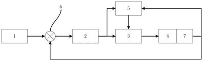
fig. 3 is a system block diagram of an apparatus according to an embodiment of the present invention.
1-a remote control device; 2-a flight control module; 3-a mixing module; 4-unmanned aerial vehicle; 5-disturbance observation module; 6-an addition module; 7-balance detection module.
Detailed Description
In order to explain technical contents, structural features, and objects and effects of the present invention in detail, the following detailed description is given with reference to the accompanying drawings in conjunction with the embodiments.
Example 1
Referring to fig. 1 and fig. 2, a method for detecting a fault of an unmanned aerial vehicle power system includes:
s1, acquiring disturbance data during the flight of the unmanned aerial vehicle, wherein the disturbance data comprises disturbance vectors And direction of disturbance
 ;
;
The direction of the disturbance And the included angle between the unit vector of the ith motor shaft in the XY plane and the disturbance vector is shown.
S2, judging whether the disturbance data is larger than the preset value, if so, determining whether the disturbance data is larger than the preset value Is less than a predetermined angle threshold, and perturbs the vector
 If the modulus is larger than the threshold value, judging that the motor fails;
s3, adjusting the control signal according to the disturbance data and outputting an anti-disturbance control signal; the disturbance vector Is a mold of
 ,
, Wherein, in the step (A),
 a power matrix representing the power system is shown,
 a vector representing a power matrix of the powertrain system.
In this embodiment, take six rotor unmanned aerial vehicles as an example to explain fault detection principle and implementation process, six rotor unmanned aerial vehicle's power distributes respectively on six horn booms, is provided lift, roll, driftage and pitching moment by six motors and screw jointly, and when the driving system of each arm is all normal, because the symmetry of structure, the dynamic model of system is as follows:

the above equation shows the rotation speed of each motor, shows the lift coefficient of the propeller, shows the counter-torque coefficient of the propeller, shows the total lift generated by the system, shows the roll moment, shows the pitch moment, shows the yaw moment, a power matrix representing the power system is shown,
 a vector representing a power matrix of the powertrain system.
When some power is missing and abnormal, the power can be reflected to the control quantity of a corresponding control channel, a disturbance observer is added into a control loop, the missing power part is used as external disturbance to be estimated, and a disturbance vector can be obtained The size and direction of the (c) and (d),
 the unit vector and the disturbance vector of the ith motor shaft in the XY plane
 When the included angle is
 Less than a threshold and is summed with the disturbance vector
 Exceeds a certain threshold, at which point the motor is considered to be faulty.
The mathematical expression is as follows:

scalar quantity Indicates the magnitude of the failure of the motor numbered i when
 And when the fault is larger than the set fault threshold value, the motor can be judged to be faulty.
Under the ideal condition without external environment disturbance, when the power of one shaft is lost, the lost power is estimated to be coincident with the direction of the shaft with the lost power through disturbance estimation, and the magnitude of the lost power is related to the magnitude of the throttle at the moment, namely The disturbance vector modulus value is 0, the throttle size during suspension is generally 0.4, the disturbance influence of the environment and the data noise are considered,
 and generally cannot be 0, and needs to be determined from actual flight test data.
From the above description, the beneficial effects of the present invention are: the detection method is characterized in that the abnormal condition of power loss is treated as external disturbance, and the disturbance size and direction are obtained, so that a fault motor is positioned, a flight control system timely changes a control distribution matrix, the rest power system can keep the unmanned aerial vehicle body flying stably, and the probability of crash of the multi-rotor unmanned aerial vehicle caused by power failure is greatly reduced.
Example 2
In addition to embodiment 1, step S3 includes a step of performing matrix reallocation of the remaining motors based on the faulty motor information.
In this embodiment, when the motor numbered 1 fails, the failure power model is as follows:

the flight control module in the system changes the control distribution matrix according to the fault power model, so that the rest power system can normally execute the set control instruction, and the control effect of the flight control module on the airplane after the fault occurs in the individual motor is improved.
Example 3
In addition to embodiment 2, after step S3, the method further includes the step of sending the abnormality information to the ground station.
In this embodiment, after detecting unmanned aerial vehicle driving system trouble, in time send unmanned aerial vehicle abnormal information to the ground satellite station, be favorable to ground personnel to fix a position and track trouble unmanned aerial vehicle very first time.
Referring to fig. 3, the present invention further includes a fault detection apparatus for an unmanned aerial vehicle power system, which includes a disturbance observation module 5, a judgment module and a mixing module 3, wherein the disturbance observation module 5 is respectively connected to the judgment module and the mixing module 3,
the disturbance observation module 5 is used for acquiring disturbance data during the flight of the unmanned aerial vehicle 4;
the judging module is used for judging whether the disturbance data is larger than a preset value;
and the mixing module 3 is used for adjusting the control signal according to the disturbance data and outputting an anti-disturbance control signal.
The disturbance observation module 5 comprises a disturbance direction detection unit and a disturbance value detection unit,
the disturbance direction detection unit is used for detecting the disturbance direction ;
;
The disturbance value detection unit is used for detecting disturbance vectors 。
。
In this embodiment, a disturbance observer is added to the control loop, and the missing power portion is estimated as an external disturbance, so that the disturbance can be obtainedMotion vector The size and direction of the (c) and (d),
 the unit vector and the disturbance vector of the ith motor shaft in the XY plane
 When the included angle is
 Less than a threshold and is summed with the disturbance vector
 Exceeds a certain threshold, at which point the motor is considered to be faulty.
The invention also comprises an unmanned aerial vehicle control system, which comprises the fault detection device, a remote control module 1 and an unmanned aerial vehicle 4, wherein the remote control module 1 is connected with a flight control module 2, the flight control module 2 is connected with one input end of a mixing module 3 of the fault detection device, the fault detection device is connected with the unmanned aerial vehicle 4, the flight control module 2 comprises an addition unit 6, the unmanned aerial vehicle 4 comprises a balance detection module 7, the balance detection module 7 is respectively connected with the addition unit 6 and a disturbance observation module of the fault detection device, the disturbance observation module is connected with the other input end of the mixing module 3,
the remote control module is used for sending a flight control signal to the unmanned aerial vehicle;
the balance detection module is used for outputting an unmanned aerial vehicle attitude signal;
and the addition unit is used for adding and summing the flight control signal sent by the remote control module and the unmanned aerial vehicle attitude signal output by the balance detection module.
In the embodiment, the unmanned aerial vehicle comprises six arms, each arm is correspondingly provided with an electronic speed regulator, a motor and a propeller, an adding module 6 adds and sums aircraft attitude signals fed back by a balance detection module 7 of the unmanned aerial vehicle and remote control commands or flight programs sent by a remote control module 1 and outputs the signals to a flight control module 2, the flight control module 2 respectively sends control signals to the six electronic speed regulators, the electronic speed regulators control the rotating speed of the motors to enable the aircraft to hover, advance, retreat, translate, rotate and the like, when a certain part of a power system is abnormal, the power of the corresponding arm is lost, the attitude of the aircraft is abnormal, the balance detection module 7 of the unmanned aerial vehicle reflects the abnormal signals to the control quantity of the corresponding control channel of the flight control module 2, at the moment, a fault detection device estimates the lost power part as external disturbance, and disturbance data can be obtained, the failed horn can be positioned through further analysis, and then the flight control module 2 changes the control distribution matrix, so that the rest power system can normally reach the set control instruction, and the control effect after the single motor fails is improved.
The above description is only an embodiment of the present invention, and not intended to limit the scope of the present invention, and all modifications of equivalent structures and equivalent processes performed by the present specification and drawings, or directly or indirectly applied to other related technical fields, are included in the scope of the present invention.
Claims (6)
1. A method for detecting faults of an unmanned aerial vehicle power system comprises the following steps:
s1, acquiring disturbance data during the flight of the unmanned aerial vehicle, wherein the disturbance data comprises disturbance vectors And direction of disturbance
 ;
;
S2, judging whether the disturbance data is larger than the preset value, if so, entering S3, and if so, entering the step Is less than a predetermined angle threshold and interferes withMotion vector
 If the modulus is larger than the threshold value, judging that the motor fails;
and S3, adjusting the control signal according to the disturbance data, outputting an anti-disturbance control signal, and performing matrix redistribution on the rest motors according to the fault motor information.
2. The method of claim 1, wherein: the direction of the disturbance And the included angle between the unit vector of the ith motor shaft in the XY plane and the disturbance vector is shown.
3. The method of claim 2, wherein: the disturbance vector Is a mold of
 ,
, Wherein, in the step (A),
 a power matrix representing the power system is shown,
 a vector representing a power matrix of the powertrain system.
4. The method of claim 3, wherein: after step S3, the method further includes the step of sending the abnormality information to the ground station.
5. The utility model provides an unmanned aerial vehicle driving system fault detection device which characterized in that: comprises a disturbance observation module, a judgment module and a mixing module, wherein the disturbance observation module is respectively connected with the judgment module and the mixing module,
the disturbance observation module is used for acquiring disturbance data during the flight of the unmanned aerial vehicle;
the judging module is used for judging whether the disturbance data is larger than a preset value;
the mixing module is used for adjusting the control signal according to the disturbance data and outputting an anti-disturbance control signal;
the disturbance observation module comprises a disturbance direction detection unit and a disturbance numerical value detection unit,
the disturbance direction detection unit is used for detecting the disturbance direction ;
;
The disturbance value detection unit is used for detecting disturbance vectors 。
。
6. An unmanned aerial vehicle control system which characterized in that: comprising the fault detection device of claim 5, a remote control module and an unmanned aerial vehicle, the remote control module being connected to a flight control module, the flight control module being connected to one input of a hybrid module of the fault detection device, the fault detection device being connected to the unmanned aerial vehicle, the flight control module comprising an addition unit, the unmanned aerial vehicle comprising a balance detection module, the balance detection module being connected to the addition unit and a disturbance observation module of the fault detection device, respectively, the disturbance observation module being connected to another input of the hybrid module,
the remote control module is used for sending a flight control signal to the unmanned aerial vehicle;
the balance detection module is used for outputting an unmanned aerial vehicle attitude signal;
and the addition unit is used for adding and summing the flight control signal sent by the remote control module and the unmanned aerial vehicle attitude signal output by the balance detection module.
Priority Applications (1)
| Application Number | Priority Date | Filing Date | Title |
|---|---|---|---|
| CN201810141308.6A CN108341072B (en) | 2018-02-11 | 2018-02-11 | Method and device for detecting faults of power system of unmanned aerial vehicle and unmanned aerial vehicle |
Applications Claiming Priority (1)
| Application Number | Priority Date | Filing Date | Title |
|---|---|---|---|
| CN201810141308.6A CN108341072B (en) | 2018-02-11 | 2018-02-11 | Method and device for detecting faults of power system of unmanned aerial vehicle and unmanned aerial vehicle |
Publications (2)
| Publication Number | Publication Date |
|---|---|
| CN108341072A CN108341072A (en) | 2018-07-31 |
| CN108341072B true CN108341072B (en) | 2021-06-04 |
Family
ID=62960164
Family Applications (1)
| Application Number | Title | Priority Date | Filing Date |
|---|---|---|---|
| CN201810141308.6A Active CN108341072B (en) | 2018-02-11 | 2018-02-11 | Method and device for detecting faults of power system of unmanned aerial vehicle and unmanned aerial vehicle |
Country Status (1)
| Country | Link |
|---|---|
| CN (1) | CN108341072B (en) |
Families Citing this family (5)
| Publication number | Priority date | Publication date | Assignee | Title |
|---|---|---|---|---|
| CN108873925B (en) * | 2018-08-02 | 2021-08-24 | 深圳市吉影科技有限公司 | Fixed pitch angle motion control method and device for underwater unmanned aerial vehicle |
| CN111114763A (en) * | 2020-01-15 | 2020-05-08 | 亿航智能设备(广州)有限公司 | Active compensation method for propeller power failure, unmanned aerial vehicle and storage medium |
| CN112373677B (en) * | 2020-11-18 | 2021-06-22 | 三生万物(北京)人工智能技术有限公司 | Power loss protection system and protection method for six-rotor unmanned aerial vehicle |
| CN116848485A (en) * | 2021-03-15 | 2023-10-03 | 深圳市大疆创新科技有限公司 | Unmanned aerial vehicle control method, unmanned aerial vehicle and storage medium |
| CN115610680B (en) * | 2022-10-31 | 2024-10-11 | 航天时代飞鹏有限公司 | Unmanned aerial vehicle fault detection and redundancy control method and system |
Citations (6)
| Publication number | Priority date | Publication date | Assignee | Title |
|---|---|---|---|---|
| DE1756781C2 (en) * | 1967-07-18 | 1982-07-01 | Textron Inc., 02903 Providence, R.I. | Control and stabilization arrangement for a control device of an aircraft and method for controlling the flight condition |
| CN102464108A (en) * | 2010-11-01 | 2012-05-23 | 成都飞机工业(集团)有限责任公司 | Engine failure treating method for unmanned aerial vehicle |
| CN104443425A (en) * | 2013-09-20 | 2015-03-25 | 空中客车运营简化股份公司 | Method for identifying a piece of defective equipment in an aircraft |
| CN106020222A (en) * | 2016-06-24 | 2016-10-12 | 天津理工大学 | Active disturbance rejection control method for 3-DOF (Degree Of Freedom) helicopter attitude |
| CN106451436A (en) * | 2016-11-04 | 2017-02-22 | 广东电网有限责任公司电力科学研究院 | Method and system for comprehensively and quantitatively evaluating dynamical behaviors of generator set |
| CN107074351A (en) * | 2016-09-30 | 2017-08-18 | 深圳市大疆创新科技有限公司 | Control method, device and the unmanned vehicle of unmanned plane |
Family Cites Families (2)
| Publication number | Priority date | Publication date | Assignee | Title |
|---|---|---|---|---|
| US7117125B2 (en) * | 2003-06-18 | 2006-10-03 | Eaton Corporation | System and method for proactive motor wellness diagnosis based on potential mechanical faults |
| JP6451662B2 (en) * | 2016-02-23 | 2019-01-16 | 株式会社安川電機 | Abnormality determination device, abnormality determination program, abnormality determination system, and motor control device |
-
2018
- 2018-02-11 CN CN201810141308.6A patent/CN108341072B/en active Active
Patent Citations (6)
| Publication number | Priority date | Publication date | Assignee | Title |
|---|---|---|---|---|
| DE1756781C2 (en) * | 1967-07-18 | 1982-07-01 | Textron Inc., 02903 Providence, R.I. | Control and stabilization arrangement for a control device of an aircraft and method for controlling the flight condition |
| CN102464108A (en) * | 2010-11-01 | 2012-05-23 | 成都飞机工业(集团)有限责任公司 | Engine failure treating method for unmanned aerial vehicle |
| CN104443425A (en) * | 2013-09-20 | 2015-03-25 | 空中客车运营简化股份公司 | Method for identifying a piece of defective equipment in an aircraft |
| CN106020222A (en) * | 2016-06-24 | 2016-10-12 | 天津理工大学 | Active disturbance rejection control method for 3-DOF (Degree Of Freedom) helicopter attitude |
| CN107074351A (en) * | 2016-09-30 | 2017-08-18 | 深圳市大疆创新科技有限公司 | Control method, device and the unmanned vehicle of unmanned plane |
| CN106451436A (en) * | 2016-11-04 | 2017-02-22 | 广东电网有限责任公司电力科学研究院 | Method and system for comprehensively and quantitatively evaluating dynamical behaviors of generator set |
Also Published As
| Publication number | Publication date |
|---|---|
| CN108341072A (en) | 2018-07-31 |
Similar Documents
| Publication | Publication Date | Title |
|---|---|---|
| CN108341072B (en) | Method and device for detecting faults of power system of unmanned aerial vehicle and unmanned aerial vehicle | |
| US11640178B2 (en) | Unmanned aircraft, device for controlling unmanned aircraft, method for controlling unmanned aircraft, and device for detecting failure of unmanned aircraft | |
| Giribet et al. | Analysis and design of a tilted rotor hexacopter for fault tolerance | |
| US9650152B2 (en) | Flight envelope protection system for unmanned aerial vehicles | |
| CN106020165B (en) | A spacecraft fault-tolerant control method and verification device for actuator faults | |
| US9845148B2 (en) | Aircraft landing gear longitudinal force control | |
| CN111880410B (en) | A fault-tolerant control method for quadrotor UAV for motor failure | |
| CN113568419A (en) | A fault-tolerant control method for variable-load quadrotor UAV | |
| CN110531778A (en) | A kind of estimation of multi-rotor unmanned aerial vehicle autopilot blade damage and self-healing control method | |
| CN104765312A (en) | Implementation method for reconfigurable aircraft control system | |
| CN115629547B (en) | Control surface fault-oriented aircraft airborne fault-tolerant control method and system | |
| CN115016268B (en) | Tilting four-rotor unmanned aerial vehicle fault-tolerant control method based on sliding mode theory | |
| US12208883B2 (en) | Redundancy systems for fly-by-wire vehicles | |
| CN114740897A (en) | Flight control method, flight control system and aircraft | |
| CN111045441A (en) | A self-healing control method for composite faults of hypersonic aircraft sensors | |
| CN104699105A (en) | Method for controlling fault tolerance of six-rotor aircraft | |
| EP4033217B1 (en) | Aircraft and method for determining loads acting on an aircraft | |
| CN112373677B (en) | Power loss protection system and protection method for six-rotor unmanned aerial vehicle | |
| Sørensen et al. | UAV fault-tolerant control by combined L 1 adaptive backstepping and fault-dependent control allocation | |
| CN115981265A (en) | On-line Fault Detection Method for Carrier Aircraft Based on Expanded Observer | |
| CN115610680B (en) | Unmanned aerial vehicle fault detection and redundancy control method and system | |
| Kim et al. | Thrust Fault Diagnosis Using Extended Kalman Filter Considering Dynamics of Lift-Cruise UAV | |
| Yang et al. | Control system design for tiltable quad-rotor with propeller failure | |
| CN112882388B (en) | Four-rotor unmanned aerial vehicle fault detection and diagnosis method under damage of actuator | |
| Yuwei et al. | Control allocation based on adaptive nonlinear dynamic inverse and adaptive pseudo-inverse |
Legal Events
| Date | Code | Title | Description |
|---|---|---|---|
| PB01 | Publication | ||
| PB01 | Publication | ||
| SE01 | Entry into force of request for substantive examination | ||
| SE01 | Entry into force of request for substantive examination | ||
| GR01 | Patent grant | ||
| GR01 | Patent grant |