CN108331731B - Fluid delivery device - Google Patents
Fluid delivery device Download PDFInfo
- Publication number
- CN108331731B CN108331731B CN201710044308.XA CN201710044308A CN108331731B CN 108331731 B CN108331731 B CN 108331731B CN 201710044308 A CN201710044308 A CN 201710044308A CN 108331731 B CN108331731 B CN 108331731B
- Authority
- CN
- China
- Prior art keywords
- transmission unit
- fluid
- delivery device
- fluid delivery
- toggle
- Prior art date
- Legal status (The legal status is an assumption and is not a legal conclusion. Google has not performed a legal analysis and makes no representation as to the accuracy of the status listed.)
- Expired - Fee Related
Links
Images


Classifications
-
- A—HUMAN NECESSITIES
- A61—MEDICAL OR VETERINARY SCIENCE; HYGIENE
- A61M—DEVICES FOR INTRODUCING MEDIA INTO, OR ONTO, THE BODY; DEVICES FOR TRANSDUCING BODY MEDIA OR FOR TAKING MEDIA FROM THE BODY; DEVICES FOR PRODUCING OR ENDING SLEEP OR STUPOR
- A61M5/00—Devices for bringing media into the body in a subcutaneous, intra-vascular or intramuscular way; Accessories therefor, e.g. filling or cleaning devices, arm-rests
- A61M5/14—Infusion devices, e.g. infusing by gravity; Blood infusion; Accessories therefor
- A61M5/142—Pressure infusion, e.g. using pumps
- A61M5/145—Pressure infusion, e.g. using pumps using pressurised reservoirs, e.g. pressurised by means of pistons
-
- F—MECHANICAL ENGINEERING; LIGHTING; HEATING; WEAPONS; BLASTING
- F04—POSITIVE - DISPLACEMENT MACHINES FOR LIQUIDS; PUMPS FOR LIQUIDS OR ELASTIC FLUIDS
- F04B—POSITIVE-DISPLACEMENT MACHINES FOR LIQUIDS; PUMPS
- F04B13/00—Pumps specially modified to deliver fixed or variable measured quantities
-
- A—HUMAN NECESSITIES
- A61—MEDICAL OR VETERINARY SCIENCE; HYGIENE
- A61M—DEVICES FOR INTRODUCING MEDIA INTO, OR ONTO, THE BODY; DEVICES FOR TRANSDUCING BODY MEDIA OR FOR TAKING MEDIA FROM THE BODY; DEVICES FOR PRODUCING OR ENDING SLEEP OR STUPOR
- A61M5/00—Devices for bringing media into the body in a subcutaneous, intra-vascular or intramuscular way; Accessories therefor, e.g. filling or cleaning devices, arm-rests
- A61M5/178—Syringes
- A61M5/31—Details
- A61M5/315—Pistons; Piston-rods; Guiding, blocking or restricting the movement of the rod or piston; Appliances on the rod for facilitating dosing ; Dosing mechanisms
- A61M5/31511—Piston or piston-rod constructions, e.g. connection of piston with piston-rod
-
- F—MECHANICAL ENGINEERING; LIGHTING; HEATING; WEAPONS; BLASTING
- F04—POSITIVE - DISPLACEMENT MACHINES FOR LIQUIDS; PUMPS FOR LIQUIDS OR ELASTIC FLUIDS
- F04B—POSITIVE-DISPLACEMENT MACHINES FOR LIQUIDS; PUMPS
- F04B13/00—Pumps specially modified to deliver fixed or variable measured quantities
- F04B13/02—Pumps specially modified to deliver fixed or variable measured quantities of two or more fluids at the same time
-
- F—MECHANICAL ENGINEERING; LIGHTING; HEATING; WEAPONS; BLASTING
- F04—POSITIVE - DISPLACEMENT MACHINES FOR LIQUIDS; PUMPS FOR LIQUIDS OR ELASTIC FLUIDS
- F04B—POSITIVE-DISPLACEMENT MACHINES FOR LIQUIDS; PUMPS
- F04B17/00—Pumps characterised by combination with, or adaptation to, specific driving engines or motors
-
- F—MECHANICAL ENGINEERING; LIGHTING; HEATING; WEAPONS; BLASTING
- F04—POSITIVE - DISPLACEMENT MACHINES FOR LIQUIDS; PUMPS FOR LIQUIDS OR ELASTIC FLUIDS
- F04B—POSITIVE-DISPLACEMENT MACHINES FOR LIQUIDS; PUMPS
- F04B49/00—Control, e.g. of pump delivery, or pump pressure of, or safety measures for, machines, pumps, or pumping installations, not otherwise provided for, or of interest apart from, groups F04B1/00 - F04B47/00
- F04B49/10—Other safety measures
-
- F—MECHANICAL ENGINEERING; LIGHTING; HEATING; WEAPONS; BLASTING
- F04—POSITIVE - DISPLACEMENT MACHINES FOR LIQUIDS; PUMPS FOR LIQUIDS OR ELASTIC FLUIDS
- F04B—POSITIVE-DISPLACEMENT MACHINES FOR LIQUIDS; PUMPS
- F04B9/00—Piston machines or pumps characterised by the driving or driven means to or from their working members
- F04B9/02—Piston machines or pumps characterised by the driving or driven means to or from their working members the means being mechanical
Landscapes
- Engineering & Computer Science (AREA)
- Health & Medical Sciences (AREA)
- Mechanical Engineering (AREA)
- General Engineering & Computer Science (AREA)
- Biomedical Technology (AREA)
- Anesthesiology (AREA)
- Vascular Medicine (AREA)
- Heart & Thoracic Surgery (AREA)
- Hematology (AREA)
- Life Sciences & Earth Sciences (AREA)
- Animal Behavior & Ethology (AREA)
- General Health & Medical Sciences (AREA)
- Public Health (AREA)
- Veterinary Medicine (AREA)
- Infusion, Injection, And Reservoir Apparatuses (AREA)
Abstract
本发明提供一种流体输送装置,其包括一流体推送模块以及一流体流通模块。流体推送模块包括一致动件、一拨动件、一第一传动单元、一第二传动单元以及一螺杆。致动件用以控制磁场的强度及频率;拨动件与致动件对应设置且位于磁场范围内,拨动件感应磁场的变化而作往复运动。第一传动单元与拨动件对应设置,受拨动件作往复运动的带动作转动运动。第二传动单元与第一传动单元平行设置,受第一传动单元作转动运动,以啮合传动作转动运动。螺杆穿设于第二传动单元,螺杆的一端设有一推液件。流体流通模块包括一储液腔室以及一输液件。
The present invention provides a fluid conveying device, which includes a fluid pushing module and a fluid circulation module. The fluid pushing module includes an actuator, a toggle member, a first transmission unit, a second transmission unit and a screw. The actuator is used to control the intensity and frequency of the magnetic field; the toggle member is correspondingly arranged with the actuator and is located within the magnetic field range, and the toggle member senses the change of the magnetic field and reciprocates. The first transmission unit is correspondingly arranged with the toggle member, and is driven to rotate by the toggle member to perform reciprocating motion. The second transmission unit is arranged in parallel with the first transmission unit, and is driven to rotate by the first transmission unit to perform meshing transmission to rotate. The screw is passed through the second transmission unit, and a fluid pushing member is provided at one end of the screw. The fluid circulation module includes a liquid storage chamber and an infusion member.
Description
技术领域technical field
本发明涉及一种流体输送装置,特别涉及一种精确且微量控制输出的流体输送装置。The present invention relates to a fluid delivery device, in particular to a fluid delivery device with precise and micro-control output.
背景技术Background technique
现今流体输送装置被广泛运用,于居家自行注射应用领域,例如糖尿病患者须每日定时施打胰岛素,或是血友病患者须定期施打凝血因子,或是其他慢性病药剂或是其他营养成分施打等等,皆需要通过微小容积的流体输送装置。Today, fluid delivery devices are widely used in home self-injection applications, such as diabetic patients who need to administer insulin regularly, or hemophiliacs who need to regularly administer blood clotting factors, or other chronic disease drugs or other nutrients. Fighting, etc., all need to pass through a small volume of fluid delivery device.
然而,为了配合各种药剂浓度与剂量的需求,如何提供一种更为精确且微量控制输出的流体输送装置,已成为本领域重要的课题之一。However, in order to meet the requirements of various drug concentrations and dosages, how to provide a more precise and micro-control output fluid delivery device has become one of the important issues in the art.
发明内容SUMMARY OF THE INVENTION
有鉴于上述课题,本发明提供一种流体输送装置,包括一流体推送模块以及一流体流通模块。流体推送模块包括一致动件、一拨动件、一第一传动单元、一第二传动单元以及一螺杆。致动件用以控制磁场的强度及频率。拨动件与致动件对应设置且位于磁场范围内,拨动件感应磁场的变化而作往复运动。第一传动单元与拨动件对应设置,受拨动件作往复运动的带动作转动运动。第二传动单元与第一传动单元平行设置,受第一传动单元作转动运动,以啮合传动作转动运动。螺杆穿设于第二传动单元,螺杆的一端设有一推液件。流体流通模块包括一储液腔室以及一输液件。储液腔室用以储存一流体,推液件滑设于储液腔室的一端部,且沿储液腔室的轴向运动,将流体推送出储液腔室。输液件连接于储液腔室,以输出流体。In view of the above problems, the present invention provides a fluid conveying device including a fluid pushing module and a fluid circulating module. The fluid pushing module includes an actuating member, a toggle member, a first transmission unit, a second transmission unit and a screw. The actuator is used to control the strength and frequency of the magnetic field. The toggle element and the actuating element are arranged correspondingly and located within the range of the magnetic field, and the toggle element performs reciprocating motion in response to the change of the magnetic field. The first transmission unit is arranged correspondingly to the toggle member, and the toggled member performs a reciprocating motion with a belt that rotates. The second transmission unit is arranged in parallel with the first transmission unit, and is rotated by the first transmission unit to rotate in a meshing transmission motion. The screw is penetrated through the second transmission unit, and one end of the screw is provided with a liquid pushing member. The fluid circulation module includes a liquid storage chamber and an infusion part. The liquid storage chamber is used for storing a fluid, and the liquid pushing member is slidably arranged on one end of the liquid storage chamber and moves along the axial direction of the liquid storage chamber to push the fluid out of the liquid storage chamber. The infusion part is connected to the liquid storage chamber to output fluid.
在一实施例中,第一传动单元及第二传动单元各别包括至少一齿轮、至少一棘轮、至少一齿条或其任意组合。In one embodiment, the first transmission unit and the second transmission unit respectively include at least one gear, at least one ratchet, at least one rack, or any combination thereof.
在一实施例中,拨动件具有至少一拨动部,拨动件于每一次往复运动时,拨动部即拨动第一传动单元。In one embodiment, the toggle member has at least one toggle portion, and each time the toggle member reciprocates, the toggle portion toggles the first transmission unit.
在一实施例中,第一传动单元还包括至少两个第一齿轮,多个所述第一齿轮彼此共轴设置,拨动部与多个所述第一齿轮的至少一者的齿槽相互配合。In one embodiment, the first transmission unit further includes at least two first gears, the plurality of first gears are arranged coaxially with each other, and the toggle portion and the tooth slots of at least one of the plurality of first gears are mutually Cooperate.
在一实施例中,第一传动单元包括一棘轮及至少一个第一齿轮,棘轮与第一齿轮彼此共轴设置,拨动部与棘轮的齿槽相互配合。In one embodiment, the first transmission unit includes a ratchet wheel and at least one first gear, the ratchet wheel and the first gear are arranged coaxially with each other, and the toggle portion cooperates with the tooth slots of the ratchet wheel.
在一实施例中,第二传动单元还包括至少一第二齿轮,第二齿轮内侧具有至少一内螺纹,内螺纹与螺杆相互配合,带动螺杆作运动。In one embodiment, the second transmission unit further includes at least one second gear, the inner side of the second gear has at least one internal thread, and the internal thread cooperates with the screw to drive the screw to move.
在一实施例中,还包括一第三传动单元,第三传动单元平行设置于第一传动单元与第二传动单元之间,其中,第三传动单元包括至少两个第三齿轮,且多个所述第三齿轮彼此共轴设置。In an embodiment, a third transmission unit is further included, and the third transmission unit is arranged in parallel between the first transmission unit and the second transmission unit, wherein the third transmission unit includes at least two third gears, and a plurality of The third gears are arranged coaxially with each other.
在一实施例中,还包括一控制模块,控制模块通过有线传输、蓝芽或其他无线传输方式,控制致动件。In one embodiment, a control module is further included, and the control module controls the actuating member through wired transmission, bluetooth or other wireless transmission methods.
如在一实施例中,控制模块更可通过手动方式控制致动件。In one embodiment, the control module may further control the actuating member manually.
在一实施例中,流体选择自包括一液体、一胶体、一气体、一微型固体或一微生物群体或其任意组合。In one embodiment, the fluid is selected to include a liquid, a colloid, a gas, a micro-solid or a population of microorganisms or any combination thereof.
在一实施例中,储液腔室为可更换式结构。In one embodiment, the liquid storage chamber is of a replaceable structure.
在一实施例中,输出部为可更换式结构。In one embodiment, the output portion is a replaceable structure.
在一实施例中,流体流通模块还包括一止逆流结构,用以防止流体逆流至储液腔室。In one embodiment, the fluid flow module further includes a backflow preventing structure to prevent the fluid from flowing back to the liquid storage chamber.
在一实施例中,拨动件还具有至少一磁性元件。In one embodiment, the toggle element further has at least one magnetic element.
在一实施例中,控制单元还包括一紧急安全装置,用以立即停止电源供应,使流体推送模块停止作动。In one embodiment, the control unit further includes an emergency safety device for immediately stopping the power supply to stop the fluid pushing module from operating.
承上所述,本发明的流体输送装置,是利用拨动件受磁性偏摆运动来拨动第一传动单元中的齿轮或棘轮,再利用各齿轮间的齿轮比的搭配设计,细化螺杆与推液件于储液腔室的推进量,由此达到精确且微量控制的流体输出的目的。此外,可通过控制单元调整致动器的磁场强度及频率,进而控制拨动件的摆动角度、摆动幅度及摆动速度等,再利用各齿轮或棘轮与螺杆的可靠的机械式传动机制,达到准确且低耗电的功效。Continuing from the above, the fluid conveying device of the present invention utilizes the magnetic yaw motion of the toggle member to toggle the gear or ratchet in the first transmission unit, and then utilizes the design of the gear ratio between the gears to refine the screw. It is related to the pushing amount of the pusher in the liquid storage chamber, so as to achieve the purpose of precise and micro-controlled fluid output. In addition, the magnetic field strength and frequency of the actuator can be adjusted by the control unit, and then the swing angle, swing amplitude and swing speed of the toggle can be controlled, and then the reliable mechanical transmission mechanism of each gear or ratchet and screw can be used to achieve accurate and low power consumption.
附图说明Description of drawings
图1A为本发明一实施例的一种流体输送装置的示意图。FIG. 1A is a schematic diagram of a fluid delivery device according to an embodiment of the present invention.
图1B为图1A的局部组装示意图。FIG. 1B is a partial assembly schematic diagram of FIG. 1A .
图2为图1A的流体推送模块的运动状态示意图。FIG. 2 is a schematic diagram of a motion state of the fluid pushing module of FIG. 1A .
图3A为本发明另一实施例的一种流体输送装置的示意图。3A is a schematic diagram of a fluid delivery device according to another embodiment of the present invention.
图3B为图3A的流体推送模块的运动状态示意图。FIG. 3B is a schematic diagram of a motion state of the fluid pushing module of FIG. 3A .
图4为本发明另一实施例的一种流体输送装置的示意图。FIG. 4 is a schematic diagram of a fluid delivery device according to another embodiment of the present invention.
图5A为本发明另一实施例的一种流体输送装置的示意图。5A is a schematic diagram of a fluid delivery device according to another embodiment of the present invention.
图5B至图5C为图5A的流体推送模块的运动状态示意图。5B to 5C are schematic diagrams of motion states of the fluid pushing module of FIG. 5A .
【符号说明】【Symbol Description】
1:流体推送模块1: Fluid push module
11:致动件11: Actuator
12:拨动件12: toggle
121、122、123:拨动部121, 122, 123: toggle
13:第一传动单元13: The first transmission unit
131、132、133、135:第一齿轮131, 132, 133, 135: first gear
134:棘轮134: Ratchet
14:第二传动单元14: The second transmission unit
141、142:第二齿轮141, 142: Second gear
15:螺杆15: Screw
16:第三传动单元16: The third transmission unit
161、162:第三齿轮161, 162: Third gear
2:流体流通模块2: Fluid flow module
21:储液腔室21: Liquid storage chamber
22:输液件22: Infusion parts
221:中空导管221: Hollow Conduit
222:输出部222: Output section
3:控制单元3: Control unit
31:按键31: Button
32:紧急安全装置32: Emergency safety device
D1、D2、D3、D4:流体输送装置D1, D2, D3, D4: Fluid Delivery Devices
O:枢孔O: pivot hole
P:推液件P: push liquid
m:磁性元件m: Magnetic element
MA:长轴方向MA: long axis direction
SP1、SP2、SP3:位移量SP1, SP2, SP3: displacement amount
θ、θ1、θ2、θ3:角度θ, θ1, θ2, θ3: Angle
具体实施方式Detailed ways
以下将参照相关附图,说明依本发明较佳实施例的一种流体输送装置,其中相同的元件将以相同的参照符号加以说明。Hereinafter, a fluid delivery device according to a preferred embodiment of the present invention will be described with reference to the accompanying drawings, wherein the same elements will be described with the same reference numerals.
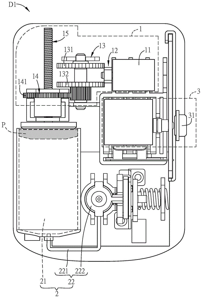
请同时参照图1A、图1B,图1A为本发明一实施例的一种流体输送装置的示意图,图1B为图1A的局部组装示意图。Please refer to FIG. 1A and FIG. 1B at the same time. FIG. 1A is a schematic diagram of a fluid delivery device according to an embodiment of the present invention, and FIG. 1B is a partial assembly diagram of FIG. 1A .
本发明提供一种流体输送装置D1,包括一流体推送模块1以及一流体流通模块2。流体推送模块1包括一致动件11、一拨动件12、一第一传动单元13、一第二传动单元14以及一螺杆15。致动件11通过电流变化以控制磁场的强度及频率,致动件11例如为一电磁铁产生装置。拨动件12与致动件11对应设置,且拨动件12大致位于磁场范围内,拨动件12可感应磁场的变化而被驱动作往复摆动运动。The present invention provides a fluid delivery device D1 , which includes a
其中,第一传动单元及第二传动单元各别包括至少一齿轮、至少一棘轮、至少一齿条或其任意组合,而拨动件12具有至少一拨动部121。The first transmission unit and the second transmission unit respectively include at least one gear, at least one ratchet, at least one rack or any combination thereof, and the
在本实施例中,第一传动单元13还包括至少两个第一齿轮131、132,多个所述第一齿轮131、132彼此共轴设置,拨动件12与多个所述第一齿轮131、132对应设置,且拨动部121与各第一齿轮131、132的齿槽相互配合。In this embodiment, the
第二传动单元14与第一传动单元13平行设置,第二传动单元14还包括至少一第二齿轮141,且该第二齿轮141内侧具有与螺杆15相互配合的至少一内螺纹,使螺杆15穿设于第二传动单元14,且螺杆15可被第二齿轮141的至少一内螺纹带动。The
流体流通模块2包括一储液腔室21以及一输液件22。储液腔室21用以储存一流体,储液腔室21可为任意适合的形状以配合流体输送装置D1结构,本实施例的储液腔室21大致为长柱型,具有一长轴方向MA。而螺杆15的一端设有一推液件P,推液件P滑设于储液腔室21的一端部E1,且沿储液腔室21的长轴方向MA作直线运动,将该流体推送出储液腔室21,此实施例中推液件P组装后保持与储液腔室21壁面密合,故流体不会自推液件P侧面流至后方。输液件22具有一中空导管221及一输出部222,中空导管221的两端分别连接于储液腔室21及输出部222,流体经输出部222离开流体输送装置D1,输出部222可以是转接头或者针头,本发明在此不予限制。The
此外,储液腔室21更可因应设计所需,配置不同的形状,而推液件P可配合储液腔室21的形状,沿储液腔室21的轴向运动。其中,储液腔室21的轴向是指储液腔室21的长轴或短轴,且推液件P配合储液腔室21的形状及设计,呈现不同的运动轨迹及方式,本发明亦不予限制。In addition, the
请同时参照图1A、图1B及图2,图2为图1A的流体推送模块的运动状态示意图,具体而言是以拨动件12具有二拨动部121、122为例,说明本实施例的流体推送模块1的运动状态。Please refer to FIGS. 1A , 1B and 2 at the same time. FIG. 2 is a schematic diagram of the motion state of the fluid pushing module of FIG. 1A , specifically, the present embodiment is described by taking the
在本实施例中,第一传动单元13具有三个第一齿轮131、132、133,其中拨动件12与第一齿轮131、132对应设置,而各拨动部121、122分别与对应的各第一齿轮132、131的齿槽相互配合。当拨动件12受致动件11的磁场的强度及频率变化感应作动,以一枢孔O为中心作一顺时针摆动一角度θ1时,拨动部121即拨动第一传动单元13的一第一齿轮132的轮齿,使该第一齿轮132转动一齿。且因多个所述第一齿轮131、132、133彼此共轴设置,使第一齿轮131、133转动角度与第一齿轮132转动角度相同。In this embodiment, the
第二传动单元14与第一传动单元13平行设置,而第二传动单元14还包括至少一第二齿轮141,本实施例中第一齿轮133与第二齿轮141彼此啮合传动,因此当第一齿轮133转动时,即带动第二齿轮141作反向转动。The
第二齿轮141内侧具有至少一内螺纹,此内螺纹与螺杆15外侧相互配合,而螺杆15的一端设有一推液件P,推液件P滑设于储液腔室21的一端部。当第二齿轮141被第一齿轮133啮合传动而作转动运动时,即带动螺杆15作直线运动,而推液件P沿储液腔室21的长轴方向MA作直线运动且位移量SP1,将内部流体推送出储液腔室21。The inner side of the
同样地,当拨动件12受另一磁场变化作用,以枢孔O为中心作一逆时针摆动一角度θ2时,拨动部122即拨动第一传动单元13的另一第一齿轮131的轮齿,使该第一齿轮131转动一齿。且因多个所述第一齿轮131、132、133彼此共轴设置,使第一齿轮132、133转动角度与第一齿轮131转动角度相同,而第二传动单元14的第二齿轮141则因受第一齿轮133啮合传动而作反向转动。且当第二齿轮141作转动运动时,即带动螺杆15作直线运动,而推液件P沿储液腔室21的长轴方向MA作直线运动且位移量SP2,将内部流体推送出储液腔室21。Similarly, when the
在本发明中,拨动件12具有至少一拨动部,本实施例有两个拨动部121、122,拨动件12于每一次往复摆动时,各该拨动部122或121即轮流各拨动第一传动单元13的对应的第一轮齿131或132,使第一传动单元13转动的齿数与多个所述拨动部121往复摆动的次数相同。因此,在相同的感磁驱动条件下往复摆动角度理应相同,以及当各拨动部121、122形状相同时,推液件P于储液腔室21内的位移量SP1、SP2则亦应相同。反之,当拨动件12的各拨动部121、122形状若为不相同时,推液件P于储液腔室21内的位移量SP1、SP2则不相同。当然,亦可因推液件P位移量的需求,将拨动件12设计为仅具有一拨动部,亦可仅对应一第一齿轮,本发明不予限制。In the present invention, the
请继续参照图3A及图3B,图3A为本发明另一实施例的一种流体输送装置的示意图,图3B为图3A的流体推送模块的运动状态示意图。本实施例的流体输送装置D2以拨动件12仅具有一拨动部121为例,说明流体推送模块1的运动状态。当拨动件12受磁场变化作用,以一枢孔O为中心作一顺时针摆动一角度θ1时,拨动部121即拨动第一传动单元13的一第一齿轮132的轮齿,使第一齿轮132转动一齿,并带动第一齿轮131、133转动相同的角度。而第二传动单元14的第二齿轮141则因第一齿轮133啮合传动而作反向转动,并带动螺杆15与推液件P沿储液腔室21的长轴方向MA作直线运动且位移量SP1。Please continue to refer to FIGS. 3A and 3B , FIG. 3A is a schematic diagram of a fluid delivery device according to another embodiment of the present invention, and FIG. 3B is a schematic diagram of a motion state of the fluid push module of FIG. 3A . In the fluid delivery device D2 of the present embodiment, the moving state of the
而当拨动件12受另一磁场变化作用,以枢孔O为中心作一逆时针摆动一角度θ2时,拨动件12与第一齿轮131并无接触,因此流体推送模块1不产生任何运动,亦即推液件P沿储液腔室21的长轴方向MA不产生位移,不会推送流体。When the
因此,若当拨动件12具有两个拨动部121、122时,拨动件12于每一次往复摆动完成时,多个所述拨动部121、122即轮流拨动第一传动单元13的总共两个轮齿,使第一传动单元13整体转动二齿,进而带动第二传动单元14,螺杆15及推液件P作二次相对运动,其整体位移量为SP1+SP2。而当拨动件12仅具有一拨动部121时,拨动件12于每一次往复摆动完成时,拨动部121仅拨动第一传动单元13的一轮齿,使第一传动单元13转动一齿,使其整体位移量为SP1。因此,使用者可通过拨动件12的拨动部121数量及/或形状的设计,控制拨动件12于每一次往复摆动完成时,流体被推送出储液腔室21的流量,亦即位移量乘上储液腔室21截面积。Therefore, if the
在本实施例中,流体输送装置D1、D2还包括一控制单元3,控制单元3可通过接收或交换有线传输、蓝芽或其他无线传输方式,及利用软体程式控制致动件11的磁场的强度及频率变化。而拨动件12还具有至少一磁性元件(附图未示),使拨动件12感应该磁场的变化而作往复摆动运动。In this embodiment, the fluid delivery devices D1 and D2 further include a
而控制单元3更可通过至少一实体按键31或至少一实体旋钮等元件的手动操作方式,以控制该致动件11的磁场的强度及频率变化。其中磁场的强度变化可控制拨动件12的摆动角度θ,而磁场发生的频率变化可控制拨动件12往复摆动的速度。因此,通过控制磁场的强度及频率变化可有效且精准控制拨动件12的往复摆动运动,再通过第一传动单元13,第二传动单元14以及螺杆15与推液件P的可靠的机械式传动机制,可进而控制流体推送出储液腔室21的流量及流速,其中摆动角度可控制流量,而摆动频率可控制流速,使流体从储液腔室21输出之流速小于0.5μL/hr,等于0.05U/hr,亦等于每日1.2U/d,其中U为胰岛素施打剂量单位。The
请继续参照图4,图4为本发明另一实施例的一种流体输送装置D3的示意图。如图4所示,本实施例可因应机身薄型化的需求,使流体输送装置D3还包括一第三传动单元16,第三传动单元16平行设置于第一传动单元13与第二传动单元14之间,其中,第三传动单元16包括至少两个第三齿轮161、162,且多个所述第三齿轮161、162彼此共轴设置。通过总计三组齿轮组传动,可使流体输送装置D3机身厚度大幅缩减,以达到整体机身薄型化功效。另一方面,通过多组传动单元的齿轮传动,更可使转动角度具有信号放大的效果,进而增加流体输出液量的精度。Please continue to refer to FIG. 4 , which is a schematic diagram of a fluid delivery device D3 according to another embodiment of the present invention. As shown in FIG. 4 , in this embodiment, in response to the requirement of thinning the body, the fluid conveying device D3 further includes a
请同时参照图5A至图5C,图5A为本发明另一实施例的一种流体输送装置的示意图,图5B至图5C为图5A的流体推送模块的运动状态示意图,具体而言是以第一传动单元13包括一棘轮134与拨动件12配合为例,说明本实施例的流体推送模块1的运动状态。Please refer to FIGS. 5A to 5C at the same time, FIG. 5A is a schematic diagram of a fluid delivery device according to another embodiment of the present invention, and FIGS. 5B to 5C are schematic diagrams of the motion state of the fluid push module of FIG. A
在本实施例中,流体输送装置D4的第一传动单元13包括一棘轮134及至少一个第一齿轮135,棘轮134与第一齿轮135彼此共轴设置,而拨动部123与棘轮134的至少一者的齿槽相互配合。当拨动件12受致动件11的磁场的强度及频率变化感应作动,以一固定摆动幅度d作周期性的直线往复运动时,拨动部123即拨动第一传动单元13的棘轮134的轮齿,使该棘轮134朝单一方向作转动运动。拨动件12于每次直线往复运动时,拨动部123仅朝单一方向拨动一次棘轮134的轮齿,使棘轮134朝单一方向转动一角度θ3。且因棘轮134与第一齿轮135彼此共轴设置,使棘轮134转动角度与第一齿轮135转动角度相同。In this embodiment, the
第二传动单元14与第一传动单元13平行设置,而第二传动单元14还包括至少一个第二齿轮142,本实施例中第一齿轮135与第二齿轮142彼此啮合传动,因此当第一齿轮135转动时,即带动第二齿轮142作反向转动。The
第二齿轮142内侧具有至少一内螺纹,此内螺纹与螺杆15外侧相互配合,而螺杆15的一端设有一推液件P,推液件P滑设于储液腔室21的一端部。当第二齿轮142被第一齿轮135啮合传动而作转动运动时,即带动螺杆15作直线运动,而使推液件P沿储液腔室21的长轴方向MA作直线运动且位移量SP3,将内部流体推送出储液腔室21。The inner side of the
在本实施例中,拨动件12具有至少一磁性元件m,流体输送装置D4更可因应不同磁场设计需求,将磁性元件m设置于拨动件12的一端部或二端部,且具至少一致动件11相对设置于拨动件12的至少一端部,使每一磁性元件m具有一配合的致动件11,使拨动件12位于磁场范围内并产生感磁运动。致动件11通过电流变化控制磁场的强度及频率,以控制拨动件12作直线往复运动的摆动幅度及摆动频率。其中,磁场的强度可控制拨动件12作直线往复运动的摆动幅度,而磁场变化的频率可控制拨动件12作直线往复运动的摆动速度。In the present embodiment, the
更进一步说明,当致动件11产生的磁场强度越大时,拨动件12受感磁作直线往复运动的摆动幅度d则越大,而拨动部123拨动第一传动单元13的棘轮134的轮齿,使该棘轮134转动角度θ3也随之越大,进而使推液件P的位移量SP3随之越大。反之,当致动件11产生的磁场强度越小时,拨动件12受感磁作直线往复运动的摆动幅度d则越小,而拨动部123拨动棘轮134的轮齿,使棘轮134转动角度θ3也随之越小,进而使推液件P的位移量SP3随之越小。同样地,致动件11产生磁场变化的频率,可控制拨动件12作直线往复运动的摆动速度的快慢,进而影响第一传动单元13、第二传动单元14以及螺杆15与推液件P的运动速度,达到控制流体推送出储液腔室21的流量及流速的目的。To further illustrate, when the intensity of the magnetic field generated by the actuating
值得说明的是,本发明公开的流体输送装置亦可因应不同领域之运用,使储液腔室21可储存不同的流体,例如一液体、一胶体、一气体、一微型固体或一微生物群体或其任意组合等,且储液腔室21与输出部222为可更换式结构,使流体输送装置可被运用于许多领域,例如慢性病患者经常会使用居家注射药剂或是其他营养成分,或是运用在显微注射技术,如实验用斑马鱼的显微注射,或是人工生殖用的精虫显微注射仪器,甚至是医美门诊使用的产品注射等等,皆可通过本发明的流体输送装置来达到其目的。It should be noted that the fluid delivery device disclosed in the present invention can also be used in different fields, so that the
更可因应安全上的需求,使流体流通模块2更可包括一止逆流结构(附图未示),用以防止流体输出后再逆流至储液腔室21,避免储液腔室21内部的流体受到污染,或者储液腔室21受到不当压力而损坏。或者如图4所示,控制单元3更可包括一紧急安全装置32,用以立即停止电源供应,使流体推送模块1停止作动。Furthermore, in response to safety requirements, the
综上所述,本发明的流体输送装置,是通过控制单元调整致动器的磁场强度及频率,进而控制拨动件的摆动角度,摆动幅度及摆动速度,再利用各齿轮组间的齿轮比的设计,细化螺杆与推液件于储液腔室的推进量,由此达到低耗电,精确且微量控制的流体输出的目的。To sum up, the fluid conveying device of the present invention adjusts the magnetic field strength and frequency of the actuator through the control unit, and then controls the swing angle, swing amplitude and swing speed of the toggle member, and then utilizes the gear ratio between the gear groups. The design refines the propulsion amount of the screw and the pusher in the liquid storage chamber, thereby achieving the purpose of low power consumption, precise and micro-controlled fluid output.
以上所述仅为举例性,而非为限制性者。任何未脱离本发明之精神与范畴,而对其进行之等效修改或变更,均应包含于后附之权利要求中。The above description is exemplary only, not limiting. Any equivalent modifications or changes without departing from the spirit and scope of the present invention should be included in the appended claims.
Claims (14)
Priority Applications (1)
| Application Number | Priority Date | Filing Date | Title |
|---|---|---|---|
| CN201710044308.XA CN108331731B (en) | 2017-01-19 | 2017-01-19 | Fluid delivery device |
Applications Claiming Priority (1)
| Application Number | Priority Date | Filing Date | Title |
|---|---|---|---|
| CN201710044308.XA CN108331731B (en) | 2017-01-19 | 2017-01-19 | Fluid delivery device |
Publications (2)
| Publication Number | Publication Date |
|---|---|
| CN108331731A CN108331731A (en) | 2018-07-27 |
| CN108331731B true CN108331731B (en) | 2020-08-21 |
Family
ID=62922157
Family Applications (1)
| Application Number | Title | Priority Date | Filing Date |
|---|---|---|---|
| CN201710044308.XA Expired - Fee Related CN108331731B (en) | 2017-01-19 | 2017-01-19 | Fluid delivery device |
Country Status (1)
| Country | Link |
|---|---|
| CN (1) | CN108331731B (en) |
Families Citing this family (5)
| Publication number | Priority date | Publication date | Assignee | Title |
|---|---|---|---|---|
| WO2020232565A1 (en) * | 2019-05-17 | 2020-11-26 | 上海移宇科技股份有限公司 | Drug infusion device |
| EP4631429A3 (en) * | 2019-07-19 | 2025-12-03 | Medtrum Technologies Inc. | Integrated drug infusion device |
| EP4007624B1 (en) * | 2019-08-01 | 2025-12-10 | Medtrum Technologies Inc. | Driving apparatus and drug infusion device |
| CN112546351B (en) * | 2020-12-21 | 2025-02-21 | 北京伏尔特技术有限公司 | A voice broadcast and data storage management system for insulin pen injection dosage |
| CN112922819B (en) * | 2021-01-28 | 2022-08-09 | 睿科集团(厦门)股份有限公司 | Method for automatically measuring compensation coefficient of peristaltic pump |
Family Cites Families (6)
| Publication number | Priority date | Publication date | Assignee | Title |
|---|---|---|---|---|
| CN101208515A (en) * | 2005-03-28 | 2008-06-25 | 因苏雷特公司 | Fluid Transfer Equipment |
| JP4355722B2 (en) * | 2005-11-17 | 2009-11-04 | セイコーエプソン株式会社 | Fluid transport device |
| CN101432601A (en) * | 2006-02-14 | 2009-05-13 | 巴特尔纪念研究院 | Accurate metering system |
| US8568361B2 (en) * | 2008-04-09 | 2013-10-29 | Medingo, Ltd. | Modular skin-adherable system for medical fluid delivery |
| EP2674177B1 (en) * | 2012-06-14 | 2021-06-30 | Stevanato Group S.P.A. | Medicament infusion device |
| CN204932474U (en) * | 2015-05-25 | 2016-01-06 | 美敦力公司 | For carrying out the fluid infusion device of administration to patient |
-
2017
- 2017-01-19 CN CN201710044308.XA patent/CN108331731B/en not_active Expired - Fee Related
Also Published As
| Publication number | Publication date |
|---|---|
| CN108331731A (en) | 2018-07-27 |
Similar Documents
| Publication | Publication Date | Title |
|---|---|---|
| CN108331731B (en) | Fluid delivery device | |
| CN113543823B (en) | drug infusion device | |
| US20240024568A1 (en) | Split piston metering pump | |
| CN103260678B (en) | Device for at least one of infusing and aspirating | |
| US8382703B1 (en) | Piezoelectric dual-syringe insulin pump | |
| EP2881128B1 (en) | Ambulatory infusion system including a step switching mechanism for valve control | |
| CN111939386B (en) | Bilaterally driven multi-infusion mode drug infusion device | |
| US11583632B2 (en) | Ambulatory infusion device | |
| JP2010512941A (en) | Flow controller | |
| CN204932474U (en) | For carrying out the fluid infusion device of administration to patient | |
| WO2016188427A1 (en) | Fluid infusion apparatus comprising mechanical actuating apparatus and manufacturing method for the fluid infusion apparatus | |
| JP7035269B2 (en) | Drug delivery device with gearset dosage system | |
| US20230047034A1 (en) | Infusion pumps and methods with shape memory wire driven syringe mechanism | |
| CN216908805U (en) | Medical fluid pump | |
| CN214550531U (en) | Dual-lumen injection device | |
| TWI629075B (en) | Fluid delivery device | |
| US20240110551A1 (en) | Hard seal compact, positive displacement pump with reciprocating motion | |
| CN204864339U (en) | Fluid infusion device | |
| CN112451801A (en) | Dual chamber injection device | |
| US20170095610A1 (en) | Personal injection device | |
| CN116059105A (en) | Drug delivery transmission system and card formula medicine bottle | |
| WO2026006169A1 (en) | Ratchet mechanism, system and method comprising the same including single ratchet with offset driving pawls | |
| BR112019010693B1 (en) | OUTPATIENT INFUSION APPARATUS AND OUTPATIENT INFUSION SYSTEM |
Legal Events
| Date | Code | Title | Description |
|---|---|---|---|
| PB01 | Publication | ||
| PB01 | Publication | ||
| SE01 | Entry into force of request for substantive examination | ||
| SE01 | Entry into force of request for substantive examination | ||
| GR01 | Patent grant | ||
| GR01 | Patent grant | ||
| CF01 | Termination of patent right due to non-payment of annual fee | ||
| CF01 | Termination of patent right due to non-payment of annual fee |
Granted publication date: 20200821 |