CN108303708B - Three-dimensional reconstruction system and method, mobile device, eye protection method, AR device - Google Patents
Three-dimensional reconstruction system and method, mobile device, eye protection method, AR device Download PDFInfo
- Publication number
- CN108303708B CN108303708B CN201810005653.7A CN201810005653A CN108303708B CN 108303708 B CN108303708 B CN 108303708B CN 201810005653 A CN201810005653 A CN 201810005653A CN 108303708 B CN108303708 B CN 108303708B
- Authority
- CN
- China
- Prior art keywords
- infrared
- light
- target object
- light source
- sub
- Prior art date
- Legal status (The legal status is an assumption and is not a legal conclusion. Google has not performed a legal analysis and makes no representation as to the accuracy of the status listed.)
- Active
Links
Images


Classifications
-
- G—PHYSICS
- G01—MEASURING; TESTING
- G01S—RADIO DIRECTION-FINDING; RADIO NAVIGATION; DETERMINING DISTANCE OR VELOCITY BY USE OF RADIO WAVES; LOCATING OR PRESENCE-DETECTING BY USE OF THE REFLECTION OR RERADIATION OF RADIO WAVES; ANALOGOUS ARRANGEMENTS USING OTHER WAVES
- G01S17/00—Systems using the reflection or reradiation of electromagnetic waves other than radio waves, e.g. lidar systems
- G01S17/02—Systems using the reflection of electromagnetic waves other than radio waves
- G01S17/06—Systems determining position data of a target
- G01S17/08—Systems determining position data of a target for measuring distance only
-
- G—PHYSICS
- G01—MEASURING; TESTING
- G01S—RADIO DIRECTION-FINDING; RADIO NAVIGATION; DETERMINING DISTANCE OR VELOCITY BY USE OF RADIO WAVES; LOCATING OR PRESENCE-DETECTING BY USE OF THE REFLECTION OR RERADIATION OF RADIO WAVES; ANALOGOUS ARRANGEMENTS USING OTHER WAVES
- G01S17/00—Systems using the reflection or reradiation of electromagnetic waves other than radio waves, e.g. lidar systems
- G01S17/88—Lidar systems specially adapted for specific applications
- G01S17/89—Lidar systems specially adapted for specific applications for mapping or imaging
-
- G—PHYSICS
- G01—MEASURING; TESTING
- G01S—RADIO DIRECTION-FINDING; RADIO NAVIGATION; DETERMINING DISTANCE OR VELOCITY BY USE OF RADIO WAVES; LOCATING OR PRESENCE-DETECTING BY USE OF THE REFLECTION OR RERADIATION OF RADIO WAVES; ANALOGOUS ARRANGEMENTS USING OTHER WAVES
- G01S7/00—Details of systems according to groups G01S13/00, G01S15/00, G01S17/00
- G01S7/48—Details of systems according to groups G01S13/00, G01S15/00, G01S17/00 of systems according to group G01S17/00
- G01S7/481—Constructional features, e.g. arrangements of optical elements
- G01S7/4814—Constructional features, e.g. arrangements of optical elements of transmitters alone
- G01S7/4815—Constructional features, e.g. arrangements of optical elements of transmitters alone using multiple transmitters
Landscapes
- Physics & Mathematics (AREA)
- Engineering & Computer Science (AREA)
- Electromagnetism (AREA)
- Computer Networks & Wireless Communication (AREA)
- General Physics & Mathematics (AREA)
- Radar, Positioning & Navigation (AREA)
- Remote Sensing (AREA)
- Length Measuring Devices By Optical Means (AREA)
Abstract
本公开提供一种三维重建系统及方法、具有护眼功能的移动设备、应用于移动设备的护眼方法、以及AR设备,涉及三维信息技术领域。该三维重建系统包括:红外光源阵列,包括多个红外子光源,每个红外子光源用于发射红外光,不同红外子光源为相干光源;红外探测器,用于接收从目标对象反射的红外光,该反射的红外光为相干光源发射的干涉光束的反射光;计算模块,用于根据反射的红外光以及红外子光源发射的红外光计算目标对象上的反射点与红外子光源之间的参考距离;三维重建模块,用于根据多个参考距离对目标对象进行三维图像的重建。本公开的三维重建系统不仅技术难度低,而且结构简单、成本低廉。
The present disclosure provides a three-dimensional reconstruction system and method, a mobile device with an eye protection function, an eye protection method applied to the mobile device, and an AR device, and relates to the technical field of three-dimensional information. The three-dimensional reconstruction system includes: an infrared light source array, including a plurality of infrared sub-light sources, each infrared sub-light source is used for emitting infrared light, and different infrared sub-light sources are coherent light sources; an infrared detector is used for receiving infrared light reflected from a target object , the reflected infrared light is the reflected light of the interference beam emitted by the coherent light source; the calculation module is used to calculate the reference point between the reflection point on the target object and the infrared sub-light source according to the reflected infrared light and the infrared light emitted by the infrared sub-light source Distance; the 3D reconstruction module is used to reconstruct the 3D image of the target object according to multiple reference distances. The three-dimensional reconstruction system of the present disclosure not only has low technical difficulty, but also has a simple structure and low cost.
Description
技术领域technical field
本公开涉及三维信息技术领域,尤其涉及一种三维重建系统及方法、具有护眼功能的移动设备、应用于移动设备的护眼方法、以及AR设备。The present disclosure relates to the field of three-dimensional information technology, and in particular, to a three-dimensional reconstruction system and method, a mobile device with an eye protection function, an eye protection method applied to the mobile device, and an AR device.
背景技术Background technique
随着移动通信技术的高速发展,移动设备例如手机的应用越来越为广泛,而且智能设备的多样化功能更能吸引消费者的关注。但是,过度的沉浸于手机或者使用手机的姿势不正确,将会对眼睛造成很大的伤害,例如容易引起视疲劳或者加速近视等。因此在使用手机的过程中,提醒消费者合理并正确的使用手机十分重要。With the rapid development of mobile communication technology, mobile devices such as mobile phones are used more and more widely, and the diversified functions of smart devices can attract consumers' attention. However, excessive immersion in the mobile phone or incorrect posture of using the mobile phone will cause great damage to the eyes, such as easily causing visual fatigue or accelerating myopia. Therefore, in the process of using mobile phones, it is very important to remind consumers to use mobile phones reasonably and correctly.
传统的移动设备例如手机可以采用红外传感器来探测人脸到手机的距离,其工作原理为:红外光源发出红外光,光线到达人脸后发生反射,红外探测器接收反射光,并根据反射光的光强来判断人脸到手机的距离。这种探测方式无法计算出人脸各个部位与手机之间的距离,因此所得到的距离仅是人脸到手机之间的粗略距离。基于此,亟需提供一种新的基于三维图像的距离探测技术来实现精确的距离探测。Traditional mobile devices such as mobile phones can use infrared sensors to detect the distance from the face to the mobile phone. The working principle is: the infrared light source emits infrared light, and the light is reflected after reaching the face, and the infrared detector receives the reflected light, and according to the reflected light The light intensity is used to judge the distance between the face and the mobile phone. This detection method cannot calculate the distance between each part of the face and the mobile phone, so the obtained distance is only a rough distance between the face and the mobile phone. Based on this, it is urgent to provide a new three-dimensional image-based distance detection technology to achieve accurate distance detection.
需要说明的是,在上述背景技术部分公开的信息仅用于加强对本公开的背景的理解,因此可以包括不构成对本领域普通技术人员已知的现有技术的信息。It should be noted that the information disclosed in the above Background section is only for enhancement of understanding of the background of the present disclosure, and therefore may contain information that does not form the prior art that is already known to a person of ordinary skill in the art.
发明内容SUMMARY OF THE INVENTION
本公开的目的在于提供一种三维重建系统及方法、具有护眼功能的移动设备、应用于移动设备的护眼方法、以及AR设备,进而至少在一定程度上克服由于相关技术的限制和缺陷而导致的一个或者多个问题。The purpose of the present disclosure is to provide a three-dimensional reconstruction system and method, a mobile device with an eye protection function, an eye protection method applied to a mobile device, and an AR device, so as to overcome the limitations and defects of the related art at least to a certain extent. cause one or more problems.
本公开的其他特性和优点将通过下面的详细描述变得显然,或部分地通过本公开的实践而习得。Other features and advantages of the present disclosure will become apparent from the following detailed description, or be learned in part by practice of the present disclosure.
根据本公开的一个方面,提供一种三维重建系统,包括:According to one aspect of the present disclosure, there is provided a three-dimensional reconstruction system, comprising:
红外光源阵列,包括多个红外子光源,每个所述红外子光源用于发射红外光,不同所述红外子光源为相干光源;an infrared light source array, comprising a plurality of infrared sub-light sources, each of the infrared sub-light sources is used to emit infrared light, and the different infrared sub-light sources are coherent light sources;
红外探测器,用于接收从目标对象反射的红外光,该反射的红外光为所述相干光源发射的干涉光束的反射光;an infrared detector for receiving the infrared light reflected from the target object, where the reflected infrared light is the reflected light of the interference beam emitted by the coherent light source;
计算模块,用于根据反射的红外光以及所述红外子光源发射的红外光计算所述目标对象上的反射点与所述红外子光源之间的参考距离;以及,a calculation module, configured to calculate the reference distance between the reflection point on the target object and the infrared sub-light source according to the reflected infrared light and the infrared light emitted by the infrared sub-light source; and,
三维重建模块,用于根据多个所述参考距离对所述目标对象进行三维图像的重建。A three-dimensional reconstruction module is used for reconstructing a three-dimensional image of the target object according to a plurality of the reference distances.
本公开的一种示例性实施例中,所述三维重建系统还包括:In an exemplary embodiment of the present disclosure, the three-dimensional reconstruction system further includes:
光源控制模块,用于控制每个所述红外子光源发射预设相位的红外光,以使所述干涉光束在所述目标对象上的目标区域增强、在所述目标对象上或者所述目标对象之外的非目标区域减弱。A light source control module, configured to control each of the infrared sub-light sources to emit infrared light with a preset phase, so that the interference light beam in the target area on the target object is enhanced, on the target object or on the target object The non-target areas outside are weakened.
本公开的一种示例性实施例中,所述红外光源阵列还包括设置在所述红外子光源的出光侧的准直透镜。In an exemplary embodiment of the present disclosure, the infrared light source array further includes a collimating lens disposed on the light exit side of the infrared sub-light source.
本公开的一种示例性实施例中,所述红外探测器包括红外感光器件。In an exemplary embodiment of the present disclosure, the infrared detector includes an infrared photosensitive device.
根据本公开的一个方面,提供一种三维重建方法,包括:According to one aspect of the present disclosure, there is provided a three-dimensional reconstruction method, comprising:
利用红外光源阵列中的多个红外子光源发射相干的红外光,不同所述红外子光源为相干光源;Utilize a plurality of infrared sub-light sources in the infrared light source array to emit coherent infrared light, and the infrared sub-light sources are different coherent light sources;
利用红外探测器接收从目标对象反射的红外光,该反射的红外光为所述相干光源发射的干涉光束的反射光;using an infrared detector to receive infrared light reflected from the target object, where the reflected infrared light is the reflected light of the interference beam emitted by the coherent light source;
根据反射的红外光以及所述红外子光源发射的红外光计算所述目标对象上的反射点与所述红外子光源之间的参考距离;Calculate the reference distance between the reflection point on the target object and the infrared sub-light source according to the reflected infrared light and the infrared light emitted by the infrared sub-light source;
根据多个所述参考距离对所述目标对象进行三维图像的重建。The three-dimensional image reconstruction of the target object is performed according to a plurality of the reference distances.
本公开的一种示例性实施例中,所述利用红外光源阵列中的多个红外子光源发射相干的红外光包括:In an exemplary embodiment of the present disclosure, the utilizing a plurality of infrared sub-light sources in the infrared light source array to emit coherent infrared light includes:
控制所述红外光源阵列中的每个红外子光源发射预设相位的红外光,以使所述干涉光束在所述目标对象上的目标区域增强、在所述目标对象上或者所述目标对象之外的非目标区域减弱。Control each infrared sub-light source in the infrared light source array to emit infrared light with a preset phase, so that the target area of the interference beam on the target object is enhanced, on the target object or between the target objects. Outside non-target areas are weakened.
根据本公开的一个方面,提供一种具有护眼功能的移动设备,包括上述的三维重建系统、处理模块、以及警示模块;According to one aspect of the present disclosure, there is provided a mobile device with an eye protection function, including the above-mentioned three-dimensional reconstruction system, a processing module, and a warning module;
所述三维重建系统根据人脸的多个反射点与红外子光源之间的参考距离获取人脸的三维图像;The three-dimensional reconstruction system obtains a three-dimensional image of the face according to the reference distance between the multiple reflection points of the face and the infrared sub-light source;
所述处理模块基于所述人脸的三维图像获取人眼与移动设备之间的相对位置关系并判断该相对位置关系是否满足预设结果;The processing module obtains the relative positional relationship between the human eye and the mobile device based on the three-dimensional image of the human face and judges whether the relative positional relationship satisfies a preset result;
所述警示模块在人眼与移动设备之间的相对位置关系满足所述预设结果时发出提示音。The warning module emits a prompt sound when the relative positional relationship between the human eye and the mobile device satisfies the preset result.
本公开的一种示例性实施例中,所述预设结果包括:人眼与移动设备之间的距离小于预设距离;或者,人眼与移动设备之间的角度大于预设角度。In an exemplary embodiment of the present disclosure, the preset result includes: the distance between the human eye and the mobile device is smaller than the preset distance; or, the angle between the human eye and the mobile device is greater than the preset angle.
根据本公开的一个方面,提供一种应用于移动设备的护眼方法,包括:According to one aspect of the present disclosure, there is provided an eye protection method applied to a mobile device, comprising:
利用上述的三维重建方法根据人脸的多个反射点与红外子光源之间的参考距离获取人脸的三维图像;Utilize the above-mentioned three-dimensional reconstruction method to obtain the three-dimensional image of the human face according to the reference distance between the multiple reflection points of the human face and the infrared sub-light source;
基于所述人脸的三维图像获取人眼与移动设备之间的相对位置关系;Obtain the relative positional relationship between the human eye and the mobile device based on the three-dimensional image of the human face;
在人眼与移动设备之间的相对位置关系满足预设结果时发出提示音。When the relative positional relationship between the human eye and the mobile device satisfies the preset result, a prompt sound is emitted.
根据本公开的一个方面,提供一种增强现实AR设备,包括上述的三维重建系统。According to one aspect of the present disclosure, an augmented reality AR device is provided, including the above-mentioned three-dimensional reconstruction system.
本公开示例性实施方式所提供的三维重建系统及方法,利用多光源干涉法对目标对象的不同点进行照明,则红外探测器接收到的反射光就是目标对象表面某一点的反射光,由于不同点到红外子光源的距离不同,因此通过该方法将目标对象的所有位置历遍,即可得到其三维图像信息,从而实现对目标对象的三维图像的重建。一方面,该三维重建系统利用光的干涉实现不同点的距离检测,其技术难度相对较低;另一方面,利用相干光的相位差来实现对目标对象的扫描,相比于机械扫描的复杂结构,其不仅结构简单,同时还能减少机械转动所耗费的响应时间;再一方面,利用红外探测器进行光强的检测,无需使用高分辨率的传感器或摄像头,因此成本得以降低。In the three-dimensional reconstruction system and method provided by the exemplary embodiments of the present disclosure, the multi-light source interferometry is used to illuminate different points of the target object, and the reflected light received by the infrared detector is the reflected light of a certain point on the surface of the target object. The distance from the point to the infrared sub-light source is different, so through this method, all the positions of the target object can be traversed to obtain its three-dimensional image information, thereby realizing the reconstruction of the three-dimensional image of the target object. On the one hand, the three-dimensional reconstruction system uses the interference of light to realize the distance detection of different points, and its technical difficulty is relatively low; on the other hand, using the phase difference of coherent light to scan the target object is more complicated than mechanical scanning. The structure is not only simple in structure, but also can reduce the response time consumed by mechanical rotation; on the other hand, the use of infrared detectors for light intensity detection does not require the use of high-resolution sensors or cameras, so the cost is reduced.
应当理解的是,以上的一般描述和后文的细节描述仅是示例性和解释性的,并不能限制本公开。It is to be understood that the foregoing general description and the following detailed description are exemplary and explanatory only and are not restrictive of the present disclosure.
附图说明Description of drawings
此处的附图被并入说明书中并构成本说明书的一部分,示出了符合本公开的实施例,并与说明书一起用于解释本公开的原理。显而易见地,下面描述中的附图仅仅是本公开的一些实施例,对于本领域普通技术人员来讲,在不付出创造性劳动的前提下,还可以根据这些附图获得其他的附图。The accompanying drawings, which are incorporated in and constitute a part of this specification, illustrate embodiments consistent with the disclosure and together with the description serve to explain the principles of the disclosure. Obviously, the drawings in the following description are only some embodiments of the present disclosure, and for those of ordinary skill in the art, other drawings can also be obtained from these drawings without creative effort.
图1示意性示出本公开示例性实施例中三维重建系统的应用架构图;FIG. 1 schematically shows an application architecture diagram of a three-dimensional reconstruction system in an exemplary embodiment of the present disclosure;
图2示意性示出本公开示例性实施例中三维重建系统的功能模块图一;FIG. 2 schematically shows a functional module diagram 1 of a three-dimensional reconstruction system in an exemplary embodiment of the present disclosure;
图3示意性示出本公开示例性实施例中三维重建系统的工作原理图;FIG. 3 schematically shows a working principle diagram of a three-dimensional reconstruction system in an exemplary embodiment of the present disclosure;
图4示意性示出本公开示例性实施例中三维重建系统的功能模块图二;FIG. 4 schematically shows a functional module diagram 2 of the three-dimensional reconstruction system in an exemplary embodiment of the present disclosure;
图5示意性示出本公开示例性实施例中双光束干涉的实验示意图;FIG. 5 schematically shows an experimental schematic diagram of two-beam interference in an exemplary embodiment of the present disclosure;
图6示意性示出本公开示例性实施例中三维重建方法的流程图;FIG. 6 schematically shows a flowchart of a three-dimensional reconstruction method in an exemplary embodiment of the present disclosure;
图7示意性示出本公开示例性实施例中应用于移动设备的护眼方法流程图。FIG. 7 schematically shows a flowchart of an eye protection method applied to a mobile device in an exemplary embodiment of the present disclosure.
具体实施方式Detailed ways
现在将参考附图更全面地描述示例实施方式。然而,示例实施方式能够以多种形式实施,且不应被理解为限于在此阐述的范例;相反,提供这些实施方式使得本公开将更加全面和完整,并将示例实施方式的构思全面地传达给本领域的技术人员。所描述的特征、结构或特性可以以任何合适的方式结合在一个或更多实施方式中。Example embodiments will now be described more fully with reference to the accompanying drawings. Example embodiments, however, can be embodied in various forms and should not be construed as limited to the examples set forth herein; rather, these embodiments are provided so that this disclosure will be thorough and complete, and will fully convey the concept of example embodiments to those skilled in the art. The described features, structures, or characteristics may be combined in any suitable manner in one or more embodiments.
此外,附图仅为本公开的示意性图解,并非一定是按比例绘制。图中相同的附图标记表示相同或类似的部分,因而将省略对它们的重复描述。附图中所示的一些方框图是功能实体,不一定必须与物理或逻辑上独立的实体相对应。可以采用软件形式来实现这些功能实体,或在一个或多个硬件模块或集成电路中实现这些功能实体,或在不同网络和/或处理器装置和/或微控制器装置中实现这些功能实体。Furthermore, the drawings are merely schematic illustrations of the present disclosure and are not necessarily drawn to scale. The same reference numerals in the drawings denote the same or similar parts, and thus their repeated descriptions will be omitted. Some of the block diagrams shown in the figures are functional entities that do not necessarily necessarily correspond to physically or logically separate entities. These functional entities may be implemented in software, or in one or more hardware modules or integrated circuits, or in different networks and/or processor devices and/or microcontroller devices.
三维重建技术是指对三维物体建立适合计算机表示和处理的数学模型,是在计算机环境下对其进行处理、操作和分析其性质的基础,也是在计算机中建立表达客观世界的虚拟现实的关键技术。现有技术中,三维重建方法通常可以采用以下两种方式实现。其一,采用由线激光投射器、摄像头、以及外部辅助定位装置组成的手持式三维扫描装置,通过外部辅助定位装置进行激光跟踪或者在室内进行无线定位来实现三维扫描和重建,但该装置的体积较大。其二,采用具有后置摄像头和微型投影仪的手机,利用投射出的多幅结构光实现三维扫描和重建,但该装置的成本较高。Three-dimensional reconstruction technology refers to the establishment of a mathematical model for three-dimensional objects that is suitable for computer representation and processing. It is the basis for processing, operating and analyzing their properties in a computer environment. . In the prior art, the three-dimensional reconstruction method can generally be implemented in the following two ways. First, a handheld 3D scanning device consisting of a line laser projector, a camera, and an external auxiliary positioning device is used to perform laser tracking or indoor wireless positioning through an external auxiliary positioning device to achieve 3D scanning and reconstruction. Larger size. Second, a mobile phone with a rear camera and a micro-projector is used to realize three-dimensional scanning and reconstruction by using multiple projected structured lights, but the cost of the device is relatively high.
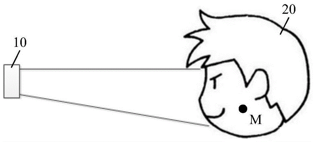
基于此,如图1所示,本示例实施方式提供一种三维重建系统10,可用于对目标对象20进行三维图像的重建。本实施例所提供的三维重建系统10具有体积小和成本低等优点,因此可适用于移动设备例如手机、AR(Augmented Reality、增强现实)设备、以及VR(Virtual Reality,虚拟现实)设备等。Based on this, as shown in FIG. 1 , the present exemplary embodiment provides a three-
图2所示为本示例实施方式所提供的三维重建系统10的功能模块图。由图可知,所述三维重建系统10主要可以包括:FIG. 2 shows a functional block diagram of the three-
红外光源阵列101,可包括图3所示的多个红外子光源100,每个红外子光源100用于发射红外光,不同红外子光源100为相干光源,即多个红外子光源100可发射相干红外光;The infrared
红外探测器102,可用于接收从目标对象反射的红外光,该反射的红外光为相干光源发射的干涉光束在目标对象的某一点的反射光;The
计算模块103,可用于根据反射的红外光以及红外子光源100发射的红外光计算目标对象上的反射点与红外子光源100之间的参考距离;以及,The
三维重建模块104,可用于根据多个反射点与红外子光源100的参考距离对目标对象进行三维图像的重建。The three-
其中,所述多个反射点与红外子光源100的参考距离应当包括尽可能多的反射点的距离信息,以此获得精确度高的三维重建图像。Wherein, the reference distances between the multiple reflection points and the infrared
需要说明的是:所述反射点是指目标对象的表面接收并反射红外光干涉光束的位置,且该位置恰好为干涉光束的亮度增强点。It should be noted that: the reflection point refers to the position where the surface of the target object receives and reflects the infrared light interference beam, and this position is exactly the brightness enhancement point of the interference beam.
本公开示例实施方式所提供的三维重建系统10,利用多光源干涉法对目标对象20的不同点进行照明,则红外探测器102接收到的反射光就是目标对象20表面某一点的反射光,由于不同点到红外子光源100的距离不同,因此通过该方法将目标对象20的所有位置历遍,即可得到其三维图像信息,从而实现对目标对象20的三维图像的重建。一方面,该三维重建系统10利用光的干涉实现不同点的距离检测,其技术难度相对较低;另一方面,利用相干光的相位差来实现对目标对象的扫描,相比于机械扫描的复杂结构,其不仅结构简单,同时还能减少机械转动所耗费的响应时间;再一方面,利用红外探测器102进行光强的检测,无需使用高分辨率的传感器或摄像头,因此成本得以降低。The three-
基于上述的三维重建系统,考虑到需要控制和调整各个红外子光源100所发射的红外光的相位,如图4所示,该三维重建系统10还可以进一步包括:Based on the above three-dimensional reconstruction system, considering that the phase of the infrared light emitted by each infrared
光源控制模块105,用于控制每个红外子光源100发射预设相位的红外光,以使干涉光束在目标对象上的目标区域M增强、在目标对象上或者目标对象之外的非目标区域减弱。The light
其中,参考图1所示,所述目标区域M是指每一次扫描过程中需要获取距离信息的部位,且本实施例优选该目标区域M为目标对象20上的一点,则该点即为干涉光束的反射点。1 , the target area M refers to the part where distance information needs to be acquired in each scanning process, and in this embodiment, it is preferable that the target area M is a point on the
这样一来,通过调整每个红外子光源100所发射的红外光的相位,即可有目的的控制干涉光束仅照亮目标对象20的一目标区域M例如某一点,此时红外探测器102接收到的反射光即为该点的反射光,由此计算出的参考距离也为该点到红外子光源100之间的距离。In this way, by adjusting the phase of the infrared light emitted by each infrared
本示例实施方式中,所述红外光源阵列101还可以包括设置在红外子光源100的出光侧的准直透镜。这样可使红外子光源100发射的红外光变为平面波,从而简化处理过程。In this exemplary embodiment, the infrared
本示例实施方式中,所述红外探测器102可以为红外传感器。本实施例中,所述红外探测器102可以仅包括红外感光器件,其相当于将红外摄像头的光学结构部分全部舍弃,因此体积较小。此外,在本实施例中,采用红外阵列光源的干涉光束的反射光来获得深度信息,只需要设置普通的感光元件即可进行测量,因此对于红外感光器件的分辨率要求较低,因此可以有效的降低成本。In this example implementation, the
由于本实施例是通过调节相干光的相位来实现对某一点距离的精确测量,继而得到全部视角范围内的距离信息,因此可实现任一点在任意时间的测量,使用更加方便灵活,且视角范围可达120°。Because this embodiment realizes the accurate measurement of the distance of a certain point by adjusting the phase of the coherent light, and then obtains the distance information within the entire viewing angle range, it can realize the measurement of any point at any time, and the use is more convenient and flexible, and the viewing angle range up to 120°.
下面结合图5以双光束干涉为例对本示例的距离检测原理进行说明。两束相干光S1和S2在空间传播过程中发生干涉而相互叠加,从而形成光强的加强区和减弱区,例如杨氏双缝实验中明暗相间的条纹。The principle of distance detection in this example will be described below with reference to FIG. 5 by taking the double-beam interference as an example. The two beams of coherent light S1 and S2 interfere with each other during the spatial propagation process and superimpose each other, thereby forming an enhanced region and a weakened region of light intensity, such as the bright and dark fringes in Young's double slit experiment.
在双光束干涉的情况下,空间任一点的光强度可以通过如下公式进行计算:In the case of double beam interference, the light intensity at any point in space can be calculated by the following formula:
I(r)=I1+I2+2×[(I1×I2)cos(θ1-θ2)]2;I(r)=I 1 +I 2 +2×[(I 1 ×I 2 )cos(θ 1 −θ 2 )] 2 ;
其中,I(r)是干涉叠加后r点处的光强,I1和I2分别为两束光的光强,θ1和θ2分别为两束光的相位。Among them, I(r) is the light intensity at point r after interference superposition, I 1 and I 2 are the light intensities of the two beams, respectively, and θ 1 and θ 2 are the phases of the two beams, respectively.
由此可知,该r点处的光强度是加强还是减弱可由发生干涉的两束光的相位差决定。在此基础上,多光束干涉的效果将更进一步,即,多束光的干涉叠加可使空间大部分区域的光强度叠加后为零,而特定区域的光强度叠加后增强,从而实现特定小区域的光照。由于相干光发生干涉时光强度增加的区域到光源的距离是一定的,因此通过多束光干涉法照亮目标对象的某一点即可得到该点与光源的距离。It can be seen from this that whether the light intensity at the r point is strengthened or weakened can be determined by the phase difference of the two interfering beams. On this basis, the effect of multi-beam interference will go further, that is, the interference and superposition of multiple beams of light can make the light intensity in most areas of the space superimposed to zero, while the light intensity in a specific area is superimposed to increase, so as to achieve a specific small Lighting of the area. Since coherent light interferes, the distance from the area where the light intensity increases to the light source is certain. Therefore, the distance between the point and the light source can be obtained by illuminating a certain point of the target object by the multi-beam light interference method.
相应的,本示例实施方式还提供了一种三维重建方法,可用于对目标对象20进行三维图像的重建。如图6所示,该三维重建方法可以包括:Correspondingly, the present exemplary embodiment also provides a three-dimensional reconstruction method, which can be used to reconstruct a three-dimensional image of the
S1、利用红外光源阵列101中的多个红外子光源100发射相干的红外光,不同红外子光源100为相干光源;S1, using a plurality of infrared
S2、利用红外探测器102接收从目标对象反射的红外光,该反射的红外光为相干光源发射的干涉光束的反射光;S2, using the
S3、根据反射的红外光以及红外子光源100发射的红外光计算目标对象上的反射点与红外子光源100之间的参考距离;S3. Calculate the reference distance between the reflection point on the target object and the infrared
S4、根据多个反射点与红外子光源100的参考距离对目标对象进行三维图像的重建。S4 , reconstructing a three-dimensional image of the target object according to the reference distances between the multiple reflection points and the infrared
其中,所述多个反射点与红外子光源100的参考距离应当包括尽可能多的反射点的距离信息,以此获得精确度高的三维重建图像。Wherein, the reference distances between the multiple reflection points and the infrared
本公开示例实施方式所提供的三维重建方法,利用多光源干涉法对目标对象20的不同点进行照明,则红外探测器102接收到的反射光就是目标对象20表面某一点的反射光,由于不同点到红外子光源100的距离不同,因此通过该方法将目标对象20的所有位置历遍,即可得到其三维图像信息,从而实现对目标对象20的三维图像的重建。一方面,该三维重建系统10利用光的干涉实现不同点的距离检测,其技术难度相对较低;另一方面,利用相干光的相位差来实现对目标对象的扫描,相比于机械扫描的复杂结构,其不仅结构简单,同时还能减少机械转动所耗费的响应时间;再一方面,利用红外探测器102进行光强的检测,无需使用高分辨率的传感器或摄像头,因此成本得以降低。In the three-dimensional reconstruction method provided by the exemplary embodiment of the present disclosure, the multi-light source interferometry is used to illuminate different points of the
基于上述的三维重建方法,在利用红外光源阵列101中的多个红外子光源100发射相干的红外光时,还可以通过光源控制模块105控制红外光源阵列101中的每个红外子光源100发射预设相位的红外光,以使干涉光束在目标对象上的目标区域M增强、在目标对象上或者目标对象之外的非目标区域减弱。这样即可有目的的控制干涉光束仅照亮目标对象20的某一点,由此计算出的参考距离即为该点到红外子光源100之间的距离。Based on the above three-dimensional reconstruction method, when multiple infrared
需要说明的是:所述三维重建方法的具体细节已经在对应的三维重建系统中进行了详细的描述,这里不再赘述。It should be noted that the specific details of the three-dimensional reconstruction method have been described in detail in the corresponding three-dimensional reconstruction system, and are not repeated here.
基于上述的三维重建系统及方法,考虑到其具有技术难度低、结构简单、体积小巧、成本低廉等诸多优点,本示例实施方式还提供了一种应用该三维重建系统及方法来实现护眼功能的移动设备。Based on the above-mentioned 3D reconstruction system and method, considering that it has many advantages, such as low technical difficulty, simple structure, small size, low cost, etc., the present exemplary embodiment also provides an application of the 3D reconstruction system and method to realize the eye protection function mobile device.
图6所示为本示例实施方式所提供的具有护眼功能的移动设备的模块示意图。由图可知,所述移动设备可以包括上述的三维重建系统10、处理模块30、以及警示模块40。在此情况下,参考图1所示,所述目标对象20即为移动设备使用者的面部。FIG. 6 is a schematic block diagram of a mobile device with an eye protection function provided by this example embodiment. As can be seen from the figure, the mobile device may include the above-mentioned three-
具体而言,所述三维重建系统10可以根据人脸的多个反射点与红外子光源100之间的参考距离来获取人脸的三维图像;所述处理模块30可以基于该人脸的三维图像来获取人眼与移动设备之间的相对位置关系并判断该相对位置关系是否满足预设结果;所述警示模块40可以在人眼与移动设备之间的相对位置关系满足预设结果时发出提示音。其中,所述预设结果例如可以包括:人眼与移动设备之间的距离小于预设距离;或者,人眼与移动设备之间的角度大于预设角度。Specifically, the three-
这样一来,本示例实施方式利用三维重建系统10即可实现对移动设备使用者的整个面部扫描,从而还原出使用者的面型信息。由于多束光发生干涉的亮度增强区即光斑投射的区域是通过不同红外光的相位进行控制的,因此在还原使用者面部信息的同时,处理模块30已经获取到了面部所有部位相对于移动设备的位置关系,并以此判断该相对位置关系是否满足预设结果。在此基础上,警示模块40可在该相对位置关系满足预设结果时提示移动设备使用者设备到眼睛的距离太近或者设备不在眼睛正前方等,从而预防近视或者眼球歪斜等眼部问题,达到保护使用者眼睛的目的。In this way, the present exemplary embodiment can use the three-
相应的,本示例实施方式还提供了一种应用于移动设备的护眼方法,如图7所示,该护眼方法可以包括:Correspondingly, the present exemplary embodiment also provides an eye protection method applied to a mobile device. As shown in FIG. 7 , the eye protection method may include:
S10、利用上述的三维重建方法根据人脸的多个反射点与红外子光源100之间的参考距离获取人脸的三维图像;S10, using the above-mentioned three-dimensional reconstruction method to obtain a three-dimensional image of the human face according to the reference distance between the multiple reflection points of the human face and the infrared
S20、基于该人脸的三维图像获取人眼与移动设备之间的相对位置关系;S20, obtain the relative positional relationship between the human eye and the mobile device based on the three-dimensional image of the face;
S30、在人眼与移动设备之间的相对位置关系满足预设结果时发出提示音。S30. Send a prompt sound when the relative positional relationship between the human eye and the mobile device satisfies the preset result.
其中,所述预设结果例如可以包括:人眼与移动设备之间的距离小于预设距离;或者,人眼与移动设备之间的角度大于预设角度。The preset result may include, for example, that the distance between the human eye and the mobile device is smaller than the preset distance; or, the angle between the human eye and the mobile device is greater than the preset angle.
这样一来,本示例实施方式利用三维重建方法对移动设备使用者的整个面部扫描,从而还原出使用者的面型信息。由于多束光发生干涉的亮度增强区即光斑投射的区域是通过不同红外光的相位进行控制的,因此在还原使用者面部信息的同时已经获取到了面部所有部位相对于移动设备的位置关系,并以此判断该相对位置关系是否满足预设结果。基于此,在该相对位置关系满足预设结果时提示移动设备使用者设备到眼睛的距离太近或者设备不在眼睛正前方等,从而预防近视或者眼球歪斜等眼部问题,达到保护使用者眼睛的目的。In this way, the present exemplary embodiment uses the three-dimensional reconstruction method to scan the entire face of the user of the mobile device, so as to restore the face shape information of the user. Since the brightness enhancement area where the interference of multiple beams of light occurs, that is, the area where the light spot is projected is controlled by the phase of different infrared light, the positional relationship of all parts of the face relative to the mobile device has been obtained while restoring the user's facial information. In this way, it is judged whether the relative positional relationship satisfies the preset result. Based on this, when the relative position relationship satisfies the preset result, the mobile device user is prompted that the distance between the device and the eyes is too close or the device is not directly in front of the eyes, etc., so as to prevent eye problems such as myopia or eye skewness, and to protect the user's eyes. Purpose.
本示例实施方式还提供了一种AR设备,包括上述的三维重建系统10。该三维重建系统10可以实现准确的空间三维重建,从而为投影叠加图像提供基础。This exemplary embodiment also provides an AR device, including the above-mentioned three-
本示例实施方式还提供了一种VR设备,包括上述的三维重建系统10。该三维重建系统10可以实现准确的空间三维重建,从而为投影叠加图像提供基础。The present exemplary embodiment also provides a VR device, including the above-mentioned three-
应当注意,尽管在上文详细描述中提及了用于动作执行的设备的若干模块或者单元,但是这种划分并非强制性的。实际上,根据本公开的实施方式,上文描述的两个或更多模块或者单元的特征和功能可以在一个模块或者单元中具体化。反之,上文描述的一个模块或者单元的特征和功能可以进一步划分为由多个模块或者单元来具体化。It should be noted that although several modules or units of the apparatus for action performance are mentioned in the above detailed description, this division is not mandatory. Indeed, according to embodiments of the present disclosure, the features and functions of two or more modules or units described above may be embodied in one module or unit. Conversely, the features and functions of one module or unit described above may be further divided into multiple modules or units to be embodied.
此外,尽管在附图中以特定顺序描述了本公开中方法的各个步骤,但是,这并非要求或者暗示必须按照该特定顺序来执行这些步骤,或是必须执行全部所示的步骤才能实现期望的结果。附加的或备选的,可以省略某些步骤,将多个步骤合并为一个步骤执行,以及/或者将一个步骤分解为多个步骤执行等。Additionally, although the various steps of the methods of the present disclosure are depicted in the figures in a particular order, this does not require or imply that the steps must be performed in the particular order or that all illustrated steps must be performed to achieve the desired result. Additionally or alternatively, certain steps may be omitted, multiple steps may be combined into one step for execution, and/or one step may be decomposed into multiple steps for execution, and the like.
本领域技术人员在考虑说明书及实践这里公开的发明后,将容易想到本公开的其他实施例。本申请旨在涵盖本公开的任何变型、用途或者适应性变化,这些变型、用途或者适应性变化遵循本公开的一般性原理并包括本公开未公开的本技术领域中的公知常识或惯用技术手段。说明书和实施例仅被视为示例性的,本公开的真正范围和精神由权利要求指出。Other embodiments of the present disclosure will readily suggest themselves to those skilled in the art upon consideration of the specification and practice of the invention disclosed herein. This application is intended to cover any variations, uses, or adaptations of the present disclosure that follow the general principles of the present disclosure and include common knowledge or techniques in the technical field not disclosed by the present disclosure . The specification and examples are to be regarded as exemplary only, with the true scope and spirit of the disclosure being indicated by the claims.
应当理解的是,本公开并不局限于上面已经描述并在附图中示出的精确结构,并且可以在不脱离其范围进行各种修改和改变。本公开的范围仅由所附的权利要求来限。It is to be understood that the present disclosure is not limited to the precise structures described above and illustrated in the accompanying drawings, and that various modifications and changes may be made without departing from the scope thereof. The scope of the present disclosure is limited only by the appended claims.
Claims (6)
Priority Applications (2)
| Application Number | Priority Date | Filing Date | Title |
|---|---|---|---|
| CN201810005653.7A CN108303708B (en) | 2018-01-03 | 2018-01-03 | Three-dimensional reconstruction system and method, mobile device, eye protection method, AR device |
| US16/102,532 US11346946B2 (en) | 2018-01-03 | 2018-08-13 | Three-dimensional reconstruction system and method, mobile device, eye protection method, AR device |
Applications Claiming Priority (1)
| Application Number | Priority Date | Filing Date | Title |
|---|---|---|---|
| CN201810005653.7A CN108303708B (en) | 2018-01-03 | 2018-01-03 | Three-dimensional reconstruction system and method, mobile device, eye protection method, AR device |
Publications (2)
| Publication Number | Publication Date |
|---|---|
| CN108303708A CN108303708A (en) | 2018-07-20 |
| CN108303708B true CN108303708B (en) | 2022-07-29 |
Family
ID=62868116
Family Applications (1)
| Application Number | Title | Priority Date | Filing Date |
|---|---|---|---|
| CN201810005653.7A Active CN108303708B (en) | 2018-01-03 | 2018-01-03 | Three-dimensional reconstruction system and method, mobile device, eye protection method, AR device |
Country Status (2)
| Country | Link |
|---|---|
| US (1) | US11346946B2 (en) |
| CN (1) | CN108303708B (en) |
Families Citing this family (2)
| Publication number | Priority date | Publication date | Assignee | Title |
|---|---|---|---|---|
| US11756262B2 (en) * | 2019-06-12 | 2023-09-12 | Lg Electronics Inc. | Mobile terminal, and 3D image conversion method thereof |
| CN113450457B (en) * | 2021-08-31 | 2021-12-14 | 腾讯科技(深圳)有限公司 | Road reconstruction method, apparatus, computer device and storage medium |
Citations (7)
| Publication number | Priority date | Publication date | Assignee | Title |
|---|---|---|---|---|
| CN102397113A (en) * | 2010-09-10 | 2012-04-04 | 三维光子国际公司 | Method of data acquisition for three-dimensional imaging |
| CN104635237A (en) * | 2013-11-08 | 2015-05-20 | 波音公司 | Synthetic wave laser ranging sensors and methods |
| CN105118247A (en) * | 2015-07-21 | 2015-12-02 | 南京智松电子科技有限公司 | Glasses frame type intelligent eyesight protection instrument |
| CN106325509A (en) * | 2016-08-19 | 2017-01-11 | 北京暴风魔镜科技有限公司 | Three-dimensional gesture recognition method and system |
| CN106448086A (en) * | 2016-08-30 | 2017-02-22 | 河海大学常州校区 | Eyesight protection device and method for detecting reading posture based on TOF depth camera |
| CN106846473A (en) * | 2016-12-22 | 2017-06-13 | 上海百芝龙网络科技有限公司 | A kind of indoor three-dimensional rebuilding method based on noctovisor scan |
| CN107003391A (en) * | 2014-11-21 | 2017-08-01 | 微软技术许可有限责任公司 | Many patterned illumination optics of time-of-flight system |
Family Cites Families (7)
| Publication number | Priority date | Publication date | Assignee | Title |
|---|---|---|---|---|
| US7394064B2 (en) * | 2004-10-05 | 2008-07-01 | Halliburton Energy Services, Inc. | Measuring the weight on a drill bit during drilling operations using coherent radiation |
| US8531650B2 (en) * | 2008-07-08 | 2013-09-10 | Chiaro Technologies LLC | Multiple channel locating |
| US8922780B2 (en) * | 2009-05-14 | 2014-12-30 | Andover Photonics, Inc. | Shape measurement using microchip based fringe projection |
| US10180572B2 (en) * | 2010-02-28 | 2019-01-15 | Microsoft Technology Licensing, Llc | AR glasses with event and user action control of external applications |
| CN203941604U (en) | 2014-06-04 | 2014-11-12 | 宁波高科美电子技术有限公司 | Prevention adolescent myopia alarm |
| CN205448962U (en) | 2015-12-31 | 2016-08-10 | 深圳先进技术研究院 | Mobile terminal with three -dimensional scanning function |
| CN205862542U (en) | 2016-05-12 | 2017-01-04 | 江西合晶科技有限公司 | A kind of myopia prevention desktop goods of furniture for display rather than for use |
-
2018
- 2018-01-03 CN CN201810005653.7A patent/CN108303708B/en active Active
- 2018-08-13 US US16/102,532 patent/US11346946B2/en active Active
Patent Citations (7)
| Publication number | Priority date | Publication date | Assignee | Title |
|---|---|---|---|---|
| CN102397113A (en) * | 2010-09-10 | 2012-04-04 | 三维光子国际公司 | Method of data acquisition for three-dimensional imaging |
| CN104635237A (en) * | 2013-11-08 | 2015-05-20 | 波音公司 | Synthetic wave laser ranging sensors and methods |
| CN107003391A (en) * | 2014-11-21 | 2017-08-01 | 微软技术许可有限责任公司 | Many patterned illumination optics of time-of-flight system |
| CN105118247A (en) * | 2015-07-21 | 2015-12-02 | 南京智松电子科技有限公司 | Glasses frame type intelligent eyesight protection instrument |
| CN106325509A (en) * | 2016-08-19 | 2017-01-11 | 北京暴风魔镜科技有限公司 | Three-dimensional gesture recognition method and system |
| CN106448086A (en) * | 2016-08-30 | 2017-02-22 | 河海大学常州校区 | Eyesight protection device and method for detecting reading posture based on TOF depth camera |
| CN106846473A (en) * | 2016-12-22 | 2017-06-13 | 上海百芝龙网络科技有限公司 | A kind of indoor three-dimensional rebuilding method based on noctovisor scan |
Also Published As
| Publication number | Publication date |
|---|---|
| CN108303708A (en) | 2018-07-20 |
| US11346946B2 (en) | 2022-05-31 |
| US20190204439A1 (en) | 2019-07-04 |
Similar Documents
| Publication | Publication Date | Title |
|---|---|---|
| US11042034B2 (en) | Head mounted display calibration using portable docking station with calibration target | |
| US11625845B2 (en) | Depth measurement assembly with a structured light source and a time of flight camera | |
| US10571668B2 (en) | Catadioptric projector systems, devices, and methods | |
| US10595014B2 (en) | Object distance determination from image | |
| US20180046874A1 (en) | System and method for marker based tracking | |
| US20160327385A1 (en) | Distance sensor | |
| US20150054918A1 (en) | Three-dimensional scanner | |
| US20190304116A1 (en) | External ir illuminator enabling improved head tracking and surface reconstruction for virtual reality | |
| CN110910506B (en) | Three-dimensional reconstruction method and device based on normal detection, detection device and system | |
| JP2009531655A (en) | Three-dimensional detection using speckle patterns | |
| US10485420B2 (en) | Eye gaze tracking | |
| CN104541126A (en) | Device for mobile pattern projection and its application | |
| US11243608B2 (en) | Control method for head-mounted visual apparatus, head-mounted visual apparatus and computer readable storage medium | |
| EP3371779A1 (en) | Systems and methods for forming models of three dimensional objects | |
| EP3443296B1 (en) | Depth sensing using structured illumination | |
| CN108303708B (en) | Three-dimensional reconstruction system and method, mobile device, eye protection method, AR device | |
| CN111121663B (en) | Object three-dimensional topography measurement method, system and computer-readable storage medium | |
| JP5441752B2 (en) | Method and apparatus for estimating a 3D pose of a 3D object in an environment | |
| Langmann | Wide area 2D/3D imaging: development, analysis and applications | |
| TW201321712A (en) | Systems and methods for determining three-dimensional absolute coordinates of objects | |
| CN117528209A (en) | Camera modules, electronic equipment, focusing methods, devices and readable storage media | |
| Munkelt et al. | Large-volume NIR pattern projection sensor for continuous low-latency 3D measurements | |
| US11917273B2 (en) | Image generating device and method thereof | |
| KR102433837B1 (en) | Apparatus for generating 3 dimention information and method for the same | |
| JP2006308452A (en) | Method and apparatus for measuring three-dimensional shape |
Legal Events
| Date | Code | Title | Description |
|---|---|---|---|
| PB01 | Publication | ||
| PB01 | Publication | ||
| SE01 | Entry into force of request for substantive examination | ||
| SE01 | Entry into force of request for substantive examination | ||
| GR01 | Patent grant | ||
| GR01 | Patent grant |