CN108291713B - Evaporation device and method for evaporating fluid - Google Patents
Evaporation device and method for evaporating fluid Download PDFInfo
- Publication number
- CN108291713B CN108291713B CN201680070693.9A CN201680070693A CN108291713B CN 108291713 B CN108291713 B CN 108291713B CN 201680070693 A CN201680070693 A CN 201680070693A CN 108291713 B CN108291713 B CN 108291713B
- Authority
- CN
- China
- Prior art keywords
- fluid
- vaporization
- bubble
- bubble pumps
- heater
- Prior art date
- Legal status (The legal status is an assumption and is not a legal conclusion. Google has not performed a legal analysis and makes no representation as to the accuracy of the status listed.)
- Active
Links
Images


Classifications
-
- A—HUMAN NECESSITIES
- A61—MEDICAL OR VETERINARY SCIENCE; HYGIENE
- A61M—DEVICES FOR INTRODUCING MEDIA INTO, OR ONTO, THE BODY; DEVICES FOR TRANSDUCING BODY MEDIA OR FOR TAKING MEDIA FROM THE BODY; DEVICES FOR PRODUCING OR ENDING SLEEP OR STUPOR
- A61M11/00—Sprayers or atomisers specially adapted for therapeutic purposes
- A61M11/04—Sprayers or atomisers specially adapted for therapeutic purposes operated by the vapour pressure of the liquid to be sprayed or atomised
- A61M11/041—Sprayers or atomisers specially adapted for therapeutic purposes operated by the vapour pressure of the liquid to be sprayed or atomised using heaters
- A61M11/042—Sprayers or atomisers specially adapted for therapeutic purposes operated by the vapour pressure of the liquid to be sprayed or atomised using heaters electrical
- A61M11/044—Sprayers or atomisers specially adapted for therapeutic purposes operated by the vapour pressure of the liquid to be sprayed or atomised using heaters electrical with electrodes immersed in the liquid
-
- A—HUMAN NECESSITIES
- A61—MEDICAL OR VETERINARY SCIENCE; HYGIENE
- A61M—DEVICES FOR INTRODUCING MEDIA INTO, OR ONTO, THE BODY; DEVICES FOR TRANSDUCING BODY MEDIA OR FOR TAKING MEDIA FROM THE BODY; DEVICES FOR PRODUCING OR ENDING SLEEP OR STUPOR
- A61M15/00—Inhalators
- A61M15/0001—Details of inhalators; Constructional features thereof
- A61M15/0003—Details of inhalators; Constructional features thereof with means for dispensing more than one drug
-
- F—MECHANICAL ENGINEERING; LIGHTING; HEATING; WEAPONS; BLASTING
- F04—POSITIVE - DISPLACEMENT MACHINES FOR LIQUIDS; PUMPS FOR LIQUIDS OR ELASTIC FLUIDS
- F04B—POSITIVE-DISPLACEMENT MACHINES FOR LIQUIDS; PUMPS
- F04B19/00—Machines or pumps having pertinent characteristics not provided for in, or of interest apart from, groups F04B1/00 - F04B17/00
- F04B19/006—Micropumps
-
- F—MECHANICAL ENGINEERING; LIGHTING; HEATING; WEAPONS; BLASTING
- F04—POSITIVE - DISPLACEMENT MACHINES FOR LIQUIDS; PUMPS FOR LIQUIDS OR ELASTIC FLUIDS
- F04B—POSITIVE-DISPLACEMENT MACHINES FOR LIQUIDS; PUMPS
- F04B19/00—Machines or pumps having pertinent characteristics not provided for in, or of interest apart from, groups F04B1/00 - F04B17/00
- F04B19/04—Pumps for special use
- F04B19/06—Pumps for delivery of both liquid and elastic fluids at the same time
-
- F—MECHANICAL ENGINEERING; LIGHTING; HEATING; WEAPONS; BLASTING
- F04—POSITIVE - DISPLACEMENT MACHINES FOR LIQUIDS; PUMPS FOR LIQUIDS OR ELASTIC FLUIDS
- F04B—POSITIVE-DISPLACEMENT MACHINES FOR LIQUIDS; PUMPS
- F04B19/00—Machines or pumps having pertinent characteristics not provided for in, or of interest apart from, groups F04B1/00 - F04B17/00
- F04B19/20—Other positive-displacement pumps
- F04B19/24—Pumping by heat expansion of pumped fluid
-
- F—MECHANICAL ENGINEERING; LIGHTING; HEATING; WEAPONS; BLASTING
- F22—STEAM GENERATION
- F22B—METHODS OF STEAM GENERATION; STEAM BOILERS
- F22B1/00—Methods of steam generation characterised by form of heating method
- F22B1/28—Methods of steam generation characterised by form of heating method in boilers heated electrically
- F22B1/282—Methods of steam generation characterised by form of heating method in boilers heated electrically with water or steam circulating in tubes or ducts
-
- A—HUMAN NECESSITIES
- A61—MEDICAL OR VETERINARY SCIENCE; HYGIENE
- A61M—DEVICES FOR INTRODUCING MEDIA INTO, OR ONTO, THE BODY; DEVICES FOR TRANSDUCING BODY MEDIA OR FOR TAKING MEDIA FROM THE BODY; DEVICES FOR PRODUCING OR ENDING SLEEP OR STUPOR
- A61M11/00—Sprayers or atomisers specially adapted for therapeutic purposes
- A61M11/04—Sprayers or atomisers specially adapted for therapeutic purposes operated by the vapour pressure of the liquid to be sprayed or atomised
- A61M11/041—Sprayers or atomisers specially adapted for therapeutic purposes operated by the vapour pressure of the liquid to be sprayed or atomised using heaters
- A61M11/042—Sprayers or atomisers specially adapted for therapeutic purposes operated by the vapour pressure of the liquid to be sprayed or atomised using heaters electrical
-
- A—HUMAN NECESSITIES
- A61—MEDICAL OR VETERINARY SCIENCE; HYGIENE
- A61M—DEVICES FOR INTRODUCING MEDIA INTO, OR ONTO, THE BODY; DEVICES FOR TRANSDUCING BODY MEDIA OR FOR TAKING MEDIA FROM THE BODY; DEVICES FOR PRODUCING OR ENDING SLEEP OR STUPOR
- A61M15/00—Inhalators
- A61M15/06—Inhaling appliances shaped like cigars, cigarettes or pipes
-
- F—MECHANICAL ENGINEERING; LIGHTING; HEATING; WEAPONS; BLASTING
- F22—STEAM GENERATION
- F22B—METHODS OF STEAM GENERATION; STEAM BOILERS
- F22B27/00—Instantaneous or flash steam boilers
Landscapes
- Engineering & Computer Science (AREA)
- Health & Medical Sciences (AREA)
- Mechanical Engineering (AREA)
- General Engineering & Computer Science (AREA)
- Life Sciences & Earth Sciences (AREA)
- Veterinary Medicine (AREA)
- Public Health (AREA)
- Anesthesiology (AREA)
- Biomedical Technology (AREA)
- Heart & Thoracic Surgery (AREA)
- Hematology (AREA)
- Bioinformatics & Cheminformatics (AREA)
- Animal Behavior & Ethology (AREA)
- General Health & Medical Sciences (AREA)
- Pulmonology (AREA)
- Pharmacology & Pharmacy (AREA)
- Sustainable Development (AREA)
- Sustainable Energy (AREA)
- Physics & Mathematics (AREA)
- Thermal Sciences (AREA)
- Feeding, Discharge, Calcimining, Fusing, And Gas-Generation Devices (AREA)
- Chemical Vapour Deposition (AREA)
- Physical Vapour Deposition (AREA)
Abstract
A fluid evaporation device (10), comprising: a fluid supply (12) containing a vaporizable fluid; a bubble pump (14) operable to pump fluid from the fluid supply (12) to an outlet (36) of the bubble pump (14); and an evaporator (16) located near the outlet (36) of the bubble pump (14) to receive the fluid from the bubble pump (14).
Description
Technical Field
The present invention relates generally to methods and apparatus for metering and vaporizing a fluid. More particularly, the present invention relates to fluid vaporization structures that utilize bubble pumps to deliver fluid to the vaporization structures.
Background
In the field of microfluidic structures, improvements are desired. This type of microfluidic structure is used to distribute a solution from a storage source to another device that can perform a secondary function. An example of an auxiliary function is the use of a heater to evaporate the solution so that the components of the solution can be delivered to perform their function in the gaseous state. Such microfluidic structures have many applications, such as for providing vapor therapy, perfuming e-cigarettes, chemical vapor reactions, and the like.
Reference list
Patent document
[ patent document 1 ] U.S. Pat. No.8,891,949
Disclosure of Invention
Technical problem
Improvements in conventional arrangements for distributing fluid from a fluid supply to an evaporative heater arrangement are desired. For example, conventional devices are often unreliable when providing a consistent and desired amount of fluid to an evaporative heater structure. As part of this problem, blockage of the flow path and reasons for incomplete travel of the fluid are common, leading to uncertainty in the amount of fluid reaching the evaporation element.
The present invention provides in an advantageous manner a method and apparatus for metering and evaporating a fluid.
Means for solving the problems
The present invention relates to a method and apparatus for metering and evaporating a fluid.
In one aspect, there is provided an evaporation apparatus comprising: a fluid supply containing a vaporizable fluid; a bubble pump operable to pump fluid from the fluid supply to an outlet of the bubble pump; and a fluid vaporization heater located near the outlet of the bubble pump to receive fluid from the bubble pump. The vaporization heater is operable to heat and thereby vaporize the received fluid.
In another aspect, there is provided an evaporation apparatus comprising: a fluid supply containing a vaporizable fluid; a bubble pump having an inlet in flow communication with the fluid supply to receive fluid from the fluid supply, a fluid flow path, a heater in flow order within the fluid flow path, and an outlet. The bubble pump is operable to pump fluid from the fluid supply to an outlet of the bubble pump. The fluid vaporization heater is located near the outlet of the bubble pump. The fluid vaporization heater has a heated fluid contact surface to receive fluid from the outlet of the bubble pump and heat the received fluid to vaporize the received fluid.
In yet another aspect, a method of vaporizing a fluid is provided. The method comprises the following steps: providing a fluid supply containing a vaporizable fluid; providing a bubble pump in fluid communication with the fluid supply and operating the bubble pump to pump fluid from the fluid supply to an outlet of the bubble pump; and providing a fluid vaporization heater located near the outlet of the bubble pump to receive fluid from the bubble pump, and operating the vaporization heater to heat and thereby vaporize the received fluid.
The invention has the advantages of
The vaporizing device according to the present invention is reliable in providing a consistent and desired amount of fluid to the vaporizing heater structure.
Drawings
Other advantages of the invention will be apparent by reference to the detailed description taken in conjunction with the accompanying drawings, in which elements are not drawn to scale to more clearly show the details, wherein like reference numerals represent like elements throughout the several views, and wherein:
FIG. 1 illustrates a fluid vaporization device in accordance with the present invention, wherein the vaporizer lies in a plane substantially parallel to a plane defined by the bubble pump;
FIG. 2 illustrates a fluid vaporization device in accordance with the present invention, wherein the vaporizer lies in a plane substantially parallel to a plane defined by the bubble pump;
FIG. 3 illustrates a fluid vaporization device in accordance with the present invention, wherein the vaporizer lies in a plane substantially parallel to a plane defined by the bubble pump;
FIG. 4 illustrates an alternative embodiment of a fluid vaporizing device wherein the vaporizer lies in a plane substantially perpendicular to the plane defined by the bubble pump;
FIG. 5 illustrates yet another alternative embodiment of a fluid-evaporating device in which the angle between the plane defined by the evaporator and the plane defined by the bubble pump is varied;
FIG. 6 illustrates yet another alternative embodiment of a fluid-evaporating device in which the angle between the plane defined by the evaporator and the plane defined by the bubble pump is varied;
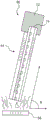
FIG. 7 shows another embodiment of a fluid vaporization device having a fluid supply inlet at an edge of the device;
FIG. 8 shows yet another embodiment of a fluid vaporizing device having a fluid supply inlet at an edge of the device, wherein the angle between the plane defined by the vaporizer of the device and the plane defined by the bubble pump of the device is varied;
FIG. 9 shows another embodiment of a fluid vaporization device in which the bubble pump and the vaporizer are fabricated on the same substrate;
FIG. 10 illustrates another embodiment of a fluid vaporization device, in which the bubble pump and the vaporizer are fabricated on the same substrate;
FIG. 11 illustrates a fluid vaporization device in accordance with the present invention, wherein the vaporizer lies in a plane substantially parallel to a plane defined by the plurality of bubble pumps;
FIG. 12 illustrates a fluid vaporization device in accordance with the present invention, wherein the vaporizer lies in a plane substantially parallel to a plane defined by the plurality of bubble pumps;
FIG. 13 illustrates an alternative embodiment of a fluid vaporizing device wherein the vaporizer lies in a plane substantially perpendicular to the plane defined by the bubble pump;
FIG. 14 shows yet another alternative embodiment of a fluid vaporizing device in which the angle between the plane defined by the vaporizer and the plane defined by the plurality of bubble pumps is varied;
FIG. 15 illustrates yet another alternative embodiment of a fluid vaporizing device wherein the angle between the plane defined by the vaporizer and the plane defined by the plurality of bubble pumps is varied;
FIG. 16 shows another embodiment of a fluid vaporization device having a fluid supply inlet at an edge of the device;
FIG. 17 illustrates yet another embodiment of a fluid vaporizing device having a fluid supply inlet located at an edge of the device, wherein the angle between the plane defined by the evaporator of the device and the plane defined by the plurality of bubble pumps of the device is varied;
FIG. 18 shows another alternative embodiment of a fluid vaporizing device having multiple bubble pumps and multiple fluid supplies;
FIG. 19 shows yet another alternative embodiment of a fluid vaporizing device having multiple bubble pumps, wherein each bubble pump has its own fluid supply;
FIG. 20 shows another embodiment of a fluid vaporization device in which the bubble pump and the vaporizer are fabricated on the same substrate; and
fig. 21 shows another embodiment of a fluid vaporizing device in which the bubble pump and the vaporizer are fabricated on the same substrate.
Detailed Description
(example 1)
The present invention relates to fluid vaporization structures that utilize one or more bubble pumps to deliver fluid from one or more fluid supplies to a separate fluid vaporization structure.
Referring to fig. 1 to 3, there is shown a fluid evaporation device 10 having a fluid supply 12, a bubble pump 14, and an evaporator 16 (fluid evaporation heater). The apparatus 10 is configured such that the bubble pump 14 delivers fluid from the fluid supply 12 directly onto the evaporator 16 as desired.
The apparatus 10 is included on a printed circuit board 18 to provide a single assembly containing the fluid supply 12, bubble pump 14 and vaporizer 16. The bubble pump 14 has a long axis that generally defines a plane and the vaporizer 16 is disposed on a substrate that generally defines a plane. As will be noted, in the embodiment of fig. 1-3, the plane defined by the bubble pump 14 and the plane defined by the evaporator 16 are substantially parallel to each other.
The fluid supply 12 is configured as a fluid storage container located on the cover substrate 20 of the bubble pump 14. The fluid supply 12 contains a desired vaporizable fluid and is typically vented to the atmosphere and contains a desired volume of fluid, typically a liquid at ambient conditions. As an example, the fluid may be a liquid of the type used for a cigarette or e-cigarette in a volume suitable for the use of the cigarette or e-cigarette. A feed inlet 22 is defined between the fluid feeder 12 and the cover substrate 20 to provide a fluid path required for fluid to travel from the fluid feeder 12 to the bubble pump 14 as desired.
The bubble pump 14 is configured to pump fluid from the fluid supply 12 to the evaporator 16. In addition to the cover substrate 20, the bubble pump 14 includes an inlet 30, a bottom substrate 32, a resistive heater 34 in flow sequence, and an outlet 36. During fabrication, the flow feature layer is first deposited on the substrate bottom 32. The flow feature layer is then selectively etched to provide the heater 34 and to define the flow channel 38.
The substrate 32 may be a semiconductor silicon substrate suitable for having bubble pumps and logic circuitry disposed thereon. The cover substrate 20 may be made of silicon or a polymer material such as polyimide. The resistive heater 34 and the evaporator 16 may be made of TaAlN, TaAl, or other thin film resistor material. A preferred material for fabricating the flow features to provide the resistive heater 34 is TaAlN deposited on the substrate bottom 32, for example by sputtering. The evaporator 16 may be formed in a similar manner.
Electrical connections and logic circuitry are integrated on the device 10 to control and operate the heater 34 and the evaporator 16 of the bubble pump 14 and, in addition, to control the transfer of fluid from the fluid supply 12 to the evaporator 16. For example, voltage pulses may be applied to the heater 34 in a desired manner to form and deliver thermal bubbles of fluid along the flow channel 38 to deliver the fluid to the evaporator 16 as desired for evaporation of the delivered fluid. An example of a preferred bubble pump is shown in U.S. patent No.8,891,949 entitled "Micro-fluidic pump," issued 11/18 2014, which is hereby incorporated by reference in its entirety.
In the basic operation of the bubble pump 14, a voltage pulse is applied to each heater 34 in turn to generate a thermal bubble in a preset manner. For example, each heater 34 may form bubbles in sequence from the inlet 30 to the outlet 36 of the channel to deliver fluid from the supply 12 to the vaporization heater 16 as desired. Each heater 34 is also allowed to cool as desired prior to the next firing sequence to prevent the fluid within the bubble pump 14 from being excessively heated and boiling.
The evaporator 16 is configured as a microfluidic electric heating element specifically designed to evaporate fluid received from the fluid supply 12. The evaporator 16 is located below and near the outlet 36 of the bubble pump 14. A slot or other flow path is formed through the circuit board 18 for fluid to travel from the outlet 36 of the bubble pump 14 to the evaporator 16. The evaporator 16 has a heated fluid contacting surface that is open to and exposed to air or other local environment. The heated fluid contacting surface heats the received fluid, evaporating the received fluid to the atmosphere or other local environment.
Referring now to fig. 4, an alternative embodiment of a fluid-evaporating device 50 is shown. The apparatus 50 has a fluid supply 52, a bubble pump 54 and an evaporator 56. The fluid supply 52 and the bubble pump 54 are included on a printed circuit board 58. The fluid supplier 52, the bubble pump 54, and the evaporator 56 substantially correspond to the fluid supplier 12, the bubble pump 14, and the evaporator 16. However, the evaporator 56 is spaced from an end portion of the circuit board 58 so as to lie in a plane substantially perpendicular to the fluid flow plane defined by the bubble pump 54.
Referring now to fig. 5 and 6, another alternative embodiment of a fluid-evaporation device 60 is shown. The device 60 substantially corresponds to the device 50 and includes the fluid supply 52, the bubble pump 54, and the evaporator 56, except that the circuit board 58 with the bubble pump 54 thereon is oriented at an angle a or an angle a 'or both an angle a and an angle a' relative to a plane defined by the evaporator 56. Angles a and a' may each vary from about 0 degrees to about 90 degrees. In this regard, it will be understood that the angles drawn are provided to illustrate that the angular orientation between the bubble pump 54 and the evaporator 56 may vary in any of three dimensions.
Referring now to fig. 7, yet another embodiment of a fluid-evaporating device 70 is shown. The device 70 substantially corresponds to the device 50 and includes the bubble pump 54, the evaporator 56 and the circuit board 58. However, the fluid supply 72 is configured to have an inlet 74 located at a distal end of the assembly of the bubble pump 54 and the circuit board 58 opposite the evaporator 56.
Referring now to fig. 8, another alternative embodiment of a fluid-evaporating device 80 is shown. The device 60 substantially corresponds to the device 70 and includes a fluid supply 72, a bubble pump 54, and an evaporator 56, except that the circuit board 58 with the bubble pump 54 thereon is oriented at an angle B relative to a plane defined by the evaporator 56. Angle B may vary from about 0 degrees to about 90 degrees. As in the case of the device 60, the angle B may be in one or more dimensions, as explained in connection with angles a and a' of fig. 5 and 6.
Referring now to fig. 9 and 10, another alternative embodiment of a fluid-evaporation device 90 is shown. The apparatus 90 substantially corresponds to the apparatus 10 and includes the fluid supply 12, the bubble pump 14, the evaporator 16, and the circuit board 18. However, the apparatus 90 is constructed by the bubble pump 14 and the vaporizer 16 fabricated on the same substrate.
(example 2)
Referring to fig. 11-12, there is shown a fluid vaporizing device 10A having a fluid supply 12, a vaporizer 16, and a plurality of bubble pumps 14. The apparatus 10A is configured such that the bubble pump 14 delivers fluid from the fluid supply 12 directly to the evaporator 16 in a desired manner.
The apparatus 10A is included on a printed circuit board 18 to provide a single assembly containing the fluid supply 12, bubble pump 14 and vaporizer 16. Each bubble pump 14 has a long axis that generally defines a plane, and the vaporizer 16 is disposed on a substrate that generally defines a plane. As will be noted, in the embodiment of fig. 11-12, the common plane defined by the bubble pumps 14 and the plane defined by the evaporator 16 are substantially parallel to each other.
The fluid supply 12 is configured as a fluid storage container on the cover substrate 20 of each bubble pump 14. The fluid supply 12 contains a desired vaporizable fluid and is typically vented to the atmosphere and contains a desired volume of fluid, typically a liquid at ambient conditions. As an example, the fluid may be a liquid of the type used for a cigarette or e-cigarette in a volume suitable for the use of the cigarette or e-cigarette. A feed inlet 22 is defined between the fluid feeder 12 and the cover substrate 20 to provide a fluid path required for fluid to travel from the fluid feeder 12 to each bubble pump 14 in a desired manner.
Each bubble pump 14 is configured to pump fluid from the fluid supply 12 to the evaporator 16. In addition to the cover substrate 20, each bubble pump 14 includes an inlet 30, a bottom substrate 32, a resistive heater 34 in flow sequence, and an outlet 36. During fabrication, the flow feature layer is first deposited on the substrate bottom 32. The flow feature layer is then selectively etched to provide the heater 34 and to define the flow channel 38. The substrate 32 may be a semiconductor silicon substrate suitable for having bubble pumps and logic circuitry disposed thereon. The cover substrate 20 may be made of silicon or a polymer material such as polyimide or the like. The resistive heater 34 and the evaporator 16 may be made of TaAlN, TaAl, or other thin film resistor material. A preferred material for fabricating the flow features to provide the resistive heater 34 is TaAlN deposited on the substrate bottom 32, for example by sputtering. The evaporator 16 may be formed in a similar manner.
Electrical connections and logic circuitry are integrated on the device 10 to control and operate the heater 34 and the evaporator 16 of the bubble pump 14 and, in addition, to control the transfer of fluid from the fluid supply 12 to the evaporator 16. For example, voltage pulses may be applied to the heater 34 in a desired manner to form and deliver thermal bubbles of fluid along the flow channel 38 to deliver the fluid to the evaporator 16 as desired for evaporation of the delivered fluid. An example of a preferred bubble pump is shown in U.S. patent No.8,891,949 entitled "Micro-fluidic pump," issued 11/18 2014, which is hereby incorporated by reference in its entirety.
In the basic operation of the bubble pump 14, a voltage pulse is applied to each heater 34 in turn to generate a thermal bubble in a preset manner. For example, each heater 34 may form bubbles in sequence from the inlet 30 to the outlet 36 of the channel to deliver fluid from the supply 12 to the vaporization heater 16 as desired. Each heater 34 is also allowed to cool as desired prior to the next firing sequence to prevent the fluid within the bubble pump 14 from being excessively heated and boiling. The bubble pump 14 may be operated to cooperate to deliver fluid to the evaporator 16.
The evaporator 16 is configured as a microfluidic electric heating element specifically designed to evaporate fluid received from the fluid supply 12. The evaporator 16 is located below and near the outlet 36 of the bubble pump 14. A slot or other flow path is formed through the circuit board 18 for fluid to travel from the outlet 36 of the bubble pump 14 to the evaporator 16. The evaporator 16 has a heated fluid contacting surface that is open to and exposed to air or other local environment. The heated fluid contacting surface heats the received fluid, evaporating the received fluid to the atmosphere or other local environment. It will be understood that the evaporator 16 may be provided by a single or multiple evaporator structure.
Referring now to fig. 13, an alternative embodiment of a fluid-evaporating device 50A is shown. The apparatus 50A has a fluid supply 52, a bubble pump 54, and an evaporator 56. The fluid supply 52 and the bubble pump 54 are included on a printed circuit board 58. The fluid supplier 52, the bubble pump 54, and the evaporator 56 substantially correspond to the fluid supplier 12, the bubble pump 14, and the evaporator 16. However, the evaporator 56 is spaced from an end portion of the circuit board 58 so as to lie in a plane substantially perpendicular to the fluid flow plane defined by the bubble pump 54.
Referring now to fig. 14 and 15, another alternative embodiment of a fluid-evaporation device 60A is shown. The device 60A substantially corresponds to the device 50A and includes the fluid supply 52, the bubble pump 54, and the evaporator 56, except that the circuit board 58 with the bubble pump 54 thereon is oriented at an angle C or angle C 'relative to a plane defined by the evaporator 56, or at both an angle C and an angle C'. Angles C and C' may each vary from about 0 degrees to about 90 degrees. In this regard, it will be understood that the angles drawn are provided to illustrate that the angular orientation between the bubble pump 54 and the evaporator 56 may vary in any of three dimensions.
Referring now to FIG. 16, yet another embodiment of a fluid-evaporating device 70A is shown. The device 70A substantially corresponds to the device 50A and includes the bubble pump 54, the evaporator 56, and the circuit board 58. However, the fluid supply 72 is configured to have an inlet 74 located at a distal end of the assembly of the bubble pump 54 and the circuit board 58 opposite the evaporator 56.
Referring now to FIG. 17, another alternative embodiment of a fluid evaporation device 80A is shown. The device 60A substantially corresponds to the device 70A and includes a fluid supply 72, a bubble pump 54, and an evaporator 56, except that the circuit board 58 with the bubble pump 54 thereon is oriented at an angle D relative to a plane defined by the evaporator 56. Angle D may vary from about 0 degrees to about 90 degrees. As in the case of device 60A, angle D may be in one or more dimensions, as explained in connection with angles C and C' of fig. 14 and 15.
Referring now to FIG. 18, another alternative embodiment of a fluid evaporation device 90A is shown. The apparatus 90A corresponds substantially to the apparatus 10A, except that the apparatus 90A includes a plurality of bubble pumps 14 in flow communication with a plurality of fluid supplies 12. It will be understood that each fluid supply 12 may comprise a different vaporizable fluid or a fluid having different properties or a mixture of fluids.
Referring now to fig. 19, another alternative embodiment of a fluid evaporation device 100 is shown. The device 100 substantially corresponds to the device 90A, except that the device 110 includes a plurality of bubble pumps 14 in the same number as the fluid supplier 12. Each bubble pump 14 is in fluid communication with a corresponding one of the fluid supplies 12. It will be understood that each fluid supply 12 may comprise a different fluid or a fluid having different characteristics or a mixture of several fluids.
Referring now to fig. 20 and 21, another alternative embodiment of a fluid-evaporating device 110 is shown. The device 110 substantially corresponds to the device 10A and includes a fluid supply 12, a bubble pump 14, an evaporator 16, and a circuit board 18. However, the apparatus 110 is constructed from the bubble pump 14 and the vaporizer 16 fabricated on the same substrate.
The foregoing description of the preferred embodiments of the present invention has been presented for purposes of illustration and description. They are not intended to be exhaustive or to limit the invention to the precise forms disclosed. Obvious modifications or variations are possible in light of the above teachings. The embodiment was chosen and described in an effort to provide the best illustrations of the principles of the invention and its practical application, to thereby enable one of ordinary skill in the art to utilize the disclosure in various embodiments and with various modifications as are suited to the particular use contemplated. All such modifications and variations are within the scope of the invention as determined by the appended claims when interpreted in accordance with the breadth to which they are fairly, legally and equitably entitled.
List of reference numerals
10, 10A, 50, 50A, 60, 60A, 70, 70A, 80, 80A, 90, 90A, 100, 110: fluid evaporation device
12, 52, 72: fluid supply device
14, 54: bubble pump
16, 56: evaporator with a heat exchanger
18, 58: printed circuit board
20: cover substrate
22: supply inlet
30, 74: inlet port
32: base substrate
34: flow-sequenced resistive heaters
36: an outlet
38: flow channel
Claims (13)
1. An evaporation apparatus comprising:
a fluid supply containing a vaporizable fluid;
a plurality of bubble pumps, each having an inlet in flow communication with the fluid supply to receive fluid from the fluid supply, a fluid flow path, a heater positioned within the fluid flow path in a flow sequence, and an outlet, wherein the plurality of bubble pumps are operable to pump fluid from the fluid supply to the respective outlets of the plurality of bubble pumps; and
a fluid vaporization heater located near each of the outlets of the plurality of bubble pumps, the fluid vaporization heater having a heated fluid contact surface to receive fluid from each of the outlets of the plurality of bubble pumps and to heat and thereby vaporize the received fluid,
the plane defined by the plurality of bubble pumps and the plane defined by the fluid vaporization heater are configured to intersect with each other,
the angular position of the plurality of bubble pumps relative to the vaporization heater is variable.
2. The vaporization unit of claim 1, wherein the plurality of bubble pumps and vaporization heaters are fabricated on a common substrate.
3. The vaporization unit of claim 1, wherein the plurality of bubble pumps and vaporization heaters are fabricated on different substrates.
4. An evaporation device as claimed in any one of claims 1 to 3, wherein the fluid supply is located vertically above the plurality of bubble pumps.
5. The evaporation device of claim 1, wherein the fluid supply, the plurality of bubble pumps, and the evaporation heater are included on a printed circuit board.
6. An evaporation device as claimed in claim 5, in which the fluid supply has an inlet at the end of the printed circuit board opposite the evaporation heater.
7. An evaporation apparatus comprising:
a fluid supply containing a vaporizable fluid;
a plurality of bubble pumps, each operable to pump fluid from a fluid supply to an outlet of the bubble pump; and
a fluid vaporization heater located proximate to each outlet of the plurality of bubble pumps to receive fluid from the plurality of bubble pumps, the vaporization heater operable to heat and thereby vaporize the received fluid,
the plane defined by the plurality of bubble pumps and the plane defined by the fluid vaporization heater are configured to intersect with each other,
the angular position of the plurality of bubble pumps relative to the vaporization heater is variable.
8. The vaporization unit of claim 7, wherein the plurality of bubble pumps and vaporization heaters are fabricated on a common substrate.
9. The vaporization unit of claim 7, wherein the plurality of bubble pumps and vaporization heaters are fabricated on different substrates.
10. An evaporation device as claimed in any one of claims 7 to 9, in which the fluid supply is located vertically above the plurality of bubble pumps.
11. The evaporation device of claim 7, wherein the fluid supply, the plurality of bubble pumps, and the evaporation heater are included on a printed circuit board.
12. The vaporization device of claim 11, wherein the fluid supply has an inlet at an end of the printed circuit board opposite the vaporization heater.
13. A method of vaporizing a fluid comprising the steps of:
providing a fluid supply containing a vaporizable fluid;
providing a plurality of bubble pumps in fluid communication with the fluid supply and operating the plurality of bubble pumps to pump fluid from the fluid supply to respective outlets of the plurality of bubble pumps; and
providing a fluid vaporization heater near each outlet of a plurality of bubble pumps to receive fluid from the plurality of bubble pumps, in a state where a plane defined by the plurality of bubble pumps and a plane defined by the fluid vaporization heater are configured to intersect with each other, and an angular position of the plurality of bubble pumps relative to the vaporization heater is variable, and operating the vaporization heater to heat and thereby vaporize the received fluid.
Applications Claiming Priority (5)
| Application Number | Priority Date | Filing Date | Title |
|---|---|---|---|
| US14/976,053 | 2015-12-21 | ||
| US14/976,067 US10344747B2 (en) | 2015-12-21 | 2015-12-21 | Method and apparatus for metering and vaporizing a fluid |
| US14/976,053 US10334879B2 (en) | 2015-12-21 | 2015-12-21 | Method and apparatus for metering and vaporizing a fluid |
| US14/976,067 | 2015-12-21 | ||
| PCT/JP2016/087716 WO2017110713A1 (en) | 2015-12-21 | 2016-12-19 | Vaporization device and method of vaporizing fluid |
Publications (2)
| Publication Number | Publication Date |
|---|---|
| CN108291713A CN108291713A (en) | 2018-07-17 |
| CN108291713B true CN108291713B (en) | 2020-06-19 |
Family
ID=59090353
Family Applications (1)
| Application Number | Title | Priority Date | Filing Date |
|---|---|---|---|
| CN201680070693.9A Active CN108291713B (en) | 2015-12-21 | 2016-12-19 | Evaporation device and method for evaporating fluid |
Country Status (4)
| Country | Link |
|---|---|
| EP (1) | EP3394510B1 (en) |
| JP (1) | JP6806149B2 (en) |
| CN (1) | CN108291713B (en) |
| WO (1) | WO2017110713A1 (en) |
Families Citing this family (19)
| Publication number | Priority date | Publication date | Assignee | Title |
|---|---|---|---|---|
| US10244793B2 (en) | 2005-07-19 | 2019-04-02 | Juul Labs, Inc. | Devices for vaporization of a substance |
| US10279934B2 (en) | 2013-03-15 | 2019-05-07 | Juul Labs, Inc. | Fillable vaporizer cartridge and method of filling |
| US10058129B2 (en) | 2013-12-23 | 2018-08-28 | Juul Labs, Inc. | Vaporization device systems and methods |
| GB2558806B8 (en) | 2013-12-23 | 2018-12-19 | Juul Labs Uk Holdco Ltd | Vaporization device systems and methods |
| USD825102S1 (en) | 2016-07-28 | 2018-08-07 | Juul Labs, Inc. | Vaporizer device with cartridge |
| US20160366947A1 (en) | 2013-12-23 | 2016-12-22 | James Monsees | Vaporizer apparatus |
| US10159282B2 (en) | 2013-12-23 | 2018-12-25 | Juul Labs, Inc. | Cartridge for use with a vaporizer device |
| US10076139B2 (en) | 2013-12-23 | 2018-09-18 | Juul Labs, Inc. | Vaporizer apparatus |
| USD842536S1 (en) | 2016-07-28 | 2019-03-05 | Juul Labs, Inc. | Vaporizer cartridge |
| EP4464356A3 (en) | 2014-12-05 | 2025-01-08 | Juul Labs, Inc. | Calibrated dose control |
| SG11201806793TA (en) | 2016-02-11 | 2018-09-27 | Juul Labs Inc | Fillable vaporizer cartridge and method of filling |
| SG10202108578XA (en) | 2016-02-11 | 2021-09-29 | Juul Labs Inc | Securely attaching cartridges for vaporizer devices |
| US10405582B2 (en) | 2016-03-10 | 2019-09-10 | Pax Labs, Inc. | Vaporization device with lip sensing |
| USD849996S1 (en) | 2016-06-16 | 2019-05-28 | Pax Labs, Inc. | Vaporizer cartridge |
| USD851830S1 (en) | 2016-06-23 | 2019-06-18 | Pax Labs, Inc. | Combined vaporizer tamp and pick tool |
| USD836541S1 (en) | 2016-06-23 | 2018-12-25 | Pax Labs, Inc. | Charging device |
| WO2019046315A1 (en) | 2017-08-28 | 2019-03-07 | Juul Labs, Inc. | Wick for vaporizer device |
| USD887632S1 (en) | 2017-09-14 | 2020-06-16 | Pax Labs, Inc. | Vaporizer cartridge |
| DE102017123867A1 (en) * | 2017-10-13 | 2019-04-18 | Hauni Maschinenbau Gmbh | Inhaler, in particular electronic cigarette product, and computer program product |
Citations (4)
| Publication number | Priority date | Publication date | Assignee | Title |
|---|---|---|---|---|
| JP2004061010A (en) * | 2002-07-30 | 2004-02-26 | Matsushita Electric Ind Co Ltd | Steam generator and cooking device provided with steam generator |
| CN1920466A (en) * | 2003-01-21 | 2007-02-28 | 三菱电机株式会社 | Vapor-lift pump heat transport apparatus |
| US8891949B2 (en) * | 2012-02-03 | 2014-11-18 | Lexmark International, Inc. | Micro-fluidic pump |
| CN104768407A (en) * | 2012-09-04 | 2015-07-08 | R·J·雷诺兹烟草公司 | Electronic smoking articles including one or more microheaters |
Family Cites Families (11)
| Publication number | Priority date | Publication date | Assignee | Title |
|---|---|---|---|---|
| JPS6479542A (en) * | 1987-09-21 | 1989-03-24 | Chubu Electric Power | Hot-water supplier |
| JPH0610900A (en) * | 1992-04-27 | 1994-01-21 | Canon Inc | Method and device for moving liquid and measuring device utilizing these method and device |
| JPH09196302A (en) * | 1996-01-24 | 1997-07-29 | Matsushita Electric Ind Co Ltd | Vapor producer |
| US6637379B2 (en) * | 2000-04-24 | 2003-10-28 | A. Western Pump & Dredge, Inc. | Accelerated water evaporation system |
| US20030175947A1 (en) * | 2001-11-05 | 2003-09-18 | Liu Robin Hui | Enhanced mixing in microfluidic devices |
| US6655924B2 (en) * | 2001-11-07 | 2003-12-02 | Intel Corporation | Peristaltic bubble pump |
| US7065907B2 (en) * | 2002-08-26 | 2006-06-27 | Koninklijke Philips Electronics N.V. | Electric steaming device |
| CN203147722U (en) * | 2012-05-21 | 2013-08-21 | 大卫·梅纳什斯 | Steam heater and kettle |
| US9387478B2 (en) * | 2012-08-17 | 2016-07-12 | Lexmark International, Inc. | Micro-fluidic modules on a chip for diagnostic applications |
| US9801415B2 (en) * | 2014-07-11 | 2017-10-31 | POSIFA Microsytems, Inc. | MEMS vaporizer |
| JP6748075B2 (en) * | 2014-10-20 | 2020-08-26 | ニューメリカル・デザイン・インコーポレイテッド | Microfluidic-based device and method for vaporization of liquids |
-
2016
- 2016-12-19 CN CN201680070693.9A patent/CN108291713B/en active Active
- 2016-12-19 JP JP2018517641A patent/JP6806149B2/en active Active
- 2016-12-19 EP EP16878602.8A patent/EP3394510B1/en active Active
- 2016-12-19 WO PCT/JP2016/087716 patent/WO2017110713A1/en active Application Filing
Patent Citations (4)
| Publication number | Priority date | Publication date | Assignee | Title |
|---|---|---|---|---|
| JP2004061010A (en) * | 2002-07-30 | 2004-02-26 | Matsushita Electric Ind Co Ltd | Steam generator and cooking device provided with steam generator |
| CN1920466A (en) * | 2003-01-21 | 2007-02-28 | 三菱电机株式会社 | Vapor-lift pump heat transport apparatus |
| US8891949B2 (en) * | 2012-02-03 | 2014-11-18 | Lexmark International, Inc. | Micro-fluidic pump |
| CN104768407A (en) * | 2012-09-04 | 2015-07-08 | R·J·雷诺兹烟草公司 | Electronic smoking articles including one or more microheaters |
Also Published As
| Publication number | Publication date |
|---|---|
| WO2017110713A1 (en) | 2017-06-29 |
| CN108291713A (en) | 2018-07-17 |
| EP3394510B1 (en) | 2022-09-14 |
| EP3394510A1 (en) | 2018-10-31 |
| JP2019504269A (en) | 2019-02-14 |
| EP3394510A4 (en) | 2019-10-09 |
| JP6806149B2 (en) | 2021-01-06 |
Similar Documents
| Publication | Publication Date | Title |
|---|---|---|
| CN108291713B (en) | Evaporation device and method for evaporating fluid | |
| KR102576372B1 (en) | Evaporator unit for inhaler and method of controlling the evaporator unit | |
| CN107076406B (en) | Microfluidic-based devices and methods for liquid evaporation | |
| US20230024534A1 (en) | Microfluidic dispenser device for delivering inhalable substances | |
| US11857722B2 (en) | Assembly comprising sheet heating element and delivery device | |
| US10440996B2 (en) | Atomizing assembly for use in an aerosol-generating system | |
| US20180213847A1 (en) | Aerosol-generating device, and method of selecting a consumable using the aerosol-generating device | |
| US10244795B2 (en) | Vaporizing assembly comprising sheet heating element and liquid delivery device for an aerosol generating system | |
| TWI322247B (en) | Delivery systems for efficient vaporization of precursor source material | |
| US12022870B2 (en) | Vaporizer for an aerosol-generating system with vaporizing method | |
| JP2019533462A5 (en) | ||
| US10334879B2 (en) | Method and apparatus for metering and vaporizing a fluid | |
| US9334566B2 (en) | Multi-tray ballast vapor draw systems | |
| US9982883B2 (en) | Vaporization system | |
| EP3471564B1 (en) | Vaporiser assembly for an aerosol-generating system | |
| US20240315338A1 (en) | Vaporizer for an aerosol-generating system and vaporizing method | |
| CN113873904A (en) | The assembly structure of the cylinder and the flat heating element of the micro-evaporator | |
| US10344747B2 (en) | Method and apparatus for metering and vaporizing a fluid | |
| EP3481441A1 (en) | Volatile substance evaporation device | |
| EP3394444B1 (en) | Micro-fluidic device |
Legal Events
| Date | Code | Title | Description |
|---|---|---|---|
| PB01 | Publication | ||
| PB01 | Publication | ||
| SE01 | Entry into force of request for substantive examination | ||
| SE01 | Entry into force of request for substantive examination | ||
| GR01 | Patent grant | ||
| GR01 | Patent grant |