CN108100128B - two wheeled vehicle - Google Patents
two wheeled vehicle Download PDFInfo
- Publication number
- CN108100128B CN108100128B CN201810044184.XA CN201810044184A CN108100128B CN 108100128 B CN108100128 B CN 108100128B CN 201810044184 A CN201810044184 A CN 201810044184A CN 108100128 B CN108100128 B CN 108100128B
- Authority
- CN
- China
- Prior art keywords
- frame
- assembly
- coupled
- swing arm
- shock absorber
- Prior art date
- Legal status (The legal status is an assumption and is not a legal conclusion. Google has not performed a legal analysis and makes no representation as to the accuracy of the status listed.)
- Active
Links
Images


Classifications
-
- B—PERFORMING OPERATIONS; TRANSPORTING
- B60—VEHICLES IN GENERAL
- B60G—VEHICLE SUSPENSION ARRANGEMENTS
- B60G7/00—Pivoted suspension arms; Accessories thereof
- B60G7/006—Attaching arms to sprung or unsprung part of vehicle, characterised by comprising attachment means controlled by an external actuator, e.g. a fluid or electrical motor
-
- B—PERFORMING OPERATIONS; TRANSPORTING
- B62—LAND VEHICLES FOR TRAVELLING OTHERWISE THAN ON RAILS
- B62K—CYCLES; CYCLE FRAMES; CYCLE STEERING DEVICES; RIDER-OPERATED TERMINAL CONTROLS SPECIALLY ADAPTED FOR CYCLES; CYCLE AXLE SUSPENSIONS; CYCLE SIDE-CARS, FORECARS, OR THE LIKE
- B62K11/00—Motorcycles, engine-assisted cycles or motor scooters with one or two wheels
- B62K11/02—Frames
-
- B—PERFORMING OPERATIONS; TRANSPORTING
- B60—VEHICLES IN GENERAL
- B60K—ARRANGEMENT OR MOUNTING OF PROPULSION UNITS OR OF TRANSMISSIONS IN VEHICLES; ARRANGEMENT OR MOUNTING OF PLURAL DIVERSE PRIME-MOVERS IN VEHICLES; AUXILIARY DRIVES FOR VEHICLES; INSTRUMENTATION OR DASHBOARDS FOR VEHICLES; ARRANGEMENTS IN CONNECTION WITH COOLING, AIR INTAKE, GAS EXHAUST OR FUEL SUPPLY OF PROPULSION UNITS IN VEHICLES
- B60K11/00—Arrangement in connection with cooling of propulsion units
- B60K11/02—Arrangement in connection with cooling of propulsion units with liquid cooling
- B60K11/04—Arrangement or mounting of radiators, radiator shutters, or radiator blinds
-
- B—PERFORMING OPERATIONS; TRANSPORTING
- B60—VEHICLES IN GENERAL
- B60K—ARRANGEMENT OR MOUNTING OF PROPULSION UNITS OR OF TRANSMISSIONS IN VEHICLES; ARRANGEMENT OR MOUNTING OF PLURAL DIVERSE PRIME-MOVERS IN VEHICLES; AUXILIARY DRIVES FOR VEHICLES; INSTRUMENTATION OR DASHBOARDS FOR VEHICLES; ARRANGEMENTS IN CONNECTION WITH COOLING, AIR INTAKE, GAS EXHAUST OR FUEL SUPPLY OF PROPULSION UNITS IN VEHICLES
- B60K13/00—Arrangement in connection with combustion air intake or gas exhaust of propulsion units
- B60K13/02—Arrangement in connection with combustion air intake or gas exhaust of propulsion units concerning intake
-
- B—PERFORMING OPERATIONS; TRANSPORTING
- B60—VEHICLES IN GENERAL
- B60K—ARRANGEMENT OR MOUNTING OF PROPULSION UNITS OR OF TRANSMISSIONS IN VEHICLES; ARRANGEMENT OR MOUNTING OF PLURAL DIVERSE PRIME-MOVERS IN VEHICLES; AUXILIARY DRIVES FOR VEHICLES; INSTRUMENTATION OR DASHBOARDS FOR VEHICLES; ARRANGEMENTS IN CONNECTION WITH COOLING, AIR INTAKE, GAS EXHAUST OR FUEL SUPPLY OF PROPULSION UNITS IN VEHICLES
- B60K13/00—Arrangement in connection with combustion air intake or gas exhaust of propulsion units
- B60K13/06—Arrangement in connection with combustion air intake or gas exhaust of propulsion units using structural parts of the vehicle as ducts, e.g. frame parts
-
- B—PERFORMING OPERATIONS; TRANSPORTING
- B60—VEHICLES IN GENERAL
- B60K—ARRANGEMENT OR MOUNTING OF PROPULSION UNITS OR OF TRANSMISSIONS IN VEHICLES; ARRANGEMENT OR MOUNTING OF PLURAL DIVERSE PRIME-MOVERS IN VEHICLES; AUXILIARY DRIVES FOR VEHICLES; INSTRUMENTATION OR DASHBOARDS FOR VEHICLES; ARRANGEMENTS IN CONNECTION WITH COOLING, AIR INTAKE, GAS EXHAUST OR FUEL SUPPLY OF PROPULSION UNITS IN VEHICLES
- B60K15/00—Arrangement in connection with fuel supply of combustion engines or other fuel consuming energy converters, e.g. fuel cells; Mounting or construction of fuel tanks
- B60K15/03—Fuel tanks
- B60K15/063—Arrangement of tanks
- B60K15/067—Mounting of tanks
-
- B—PERFORMING OPERATIONS; TRANSPORTING
- B62—LAND VEHICLES FOR TRAVELLING OTHERWISE THAN ON RAILS
- B62J—CYCLE SADDLES OR SEATS; AUXILIARY DEVICES OR ACCESSORIES SPECIALLY ADAPTED TO CYCLES AND NOT OTHERWISE PROVIDED FOR, e.g. ARTICLE CARRIERS OR CYCLE PROTECTORS
- B62J15/00—Mud-guards for wheels
- B62J15/02—Fastening means; Stays
-
- B—PERFORMING OPERATIONS; TRANSPORTING
- B62—LAND VEHICLES FOR TRAVELLING OTHERWISE THAN ON RAILS
- B62J—CYCLE SADDLES OR SEATS; AUXILIARY DEVICES OR ACCESSORIES SPECIALLY ADAPTED TO CYCLES AND NOT OTHERWISE PROVIDED FOR, e.g. ARTICLE CARRIERS OR CYCLE PROTECTORS
- B62J35/00—Fuel tanks specially adapted for motorcycles or engine-assisted cycles; Arrangements thereof
-
- B—PERFORMING OPERATIONS; TRANSPORTING
- B62—LAND VEHICLES FOR TRAVELLING OTHERWISE THAN ON RAILS
- B62K—CYCLES; CYCLE FRAMES; CYCLE STEERING DEVICES; RIDER-OPERATED TERMINAL CONTROLS SPECIALLY ADAPTED FOR CYCLES; CYCLE AXLE SUSPENSIONS; CYCLE SIDE-CARS, FORECARS, OR THE LIKE
- B62K11/00—Motorcycles, engine-assisted cycles or motor scooters with one or two wheels
- B62K11/02—Frames
- B62K11/04—Frames characterised by the engine being between front and rear wheels
- B62K11/06—Frames characterised by the engine being between front and rear wheels the frame being of single-beam type
-
- B—PERFORMING OPERATIONS; TRANSPORTING
- B62—LAND VEHICLES FOR TRAVELLING OTHERWISE THAN ON RAILS
- B62K—CYCLES; CYCLE FRAMES; CYCLE STEERING DEVICES; RIDER-OPERATED TERMINAL CONTROLS SPECIALLY ADAPTED FOR CYCLES; CYCLE AXLE SUSPENSIONS; CYCLE SIDE-CARS, FORECARS, OR THE LIKE
- B62K19/00—Cycle frames
- B62K19/18—Joints between frame members
- B62K19/24—Screwed joints
-
- B—PERFORMING OPERATIONS; TRANSPORTING
- B62—LAND VEHICLES FOR TRAVELLING OTHERWISE THAN ON RAILS
- B62K—CYCLES; CYCLE FRAMES; CYCLE STEERING DEVICES; RIDER-OPERATED TERMINAL CONTROLS SPECIALLY ADAPTED FOR CYCLES; CYCLE AXLE SUSPENSIONS; CYCLE SIDE-CARS, FORECARS, OR THE LIKE
- B62K19/00—Cycle frames
- B62K19/30—Frame parts shaped to receive other cycle parts or accessories
- B62K19/32—Steering heads
-
- B—PERFORMING OPERATIONS; TRANSPORTING
- B62—LAND VEHICLES FOR TRAVELLING OTHERWISE THAN ON RAILS
- B62K—CYCLES; CYCLE FRAMES; CYCLE STEERING DEVICES; RIDER-OPERATED TERMINAL CONTROLS SPECIALLY ADAPTED FOR CYCLES; CYCLE AXLE SUSPENSIONS; CYCLE SIDE-CARS, FORECARS, OR THE LIKE
- B62K19/00—Cycle frames
- B62K19/48—Fairings forming part of frame
-
- B—PERFORMING OPERATIONS; TRANSPORTING
- B62—LAND VEHICLES FOR TRAVELLING OTHERWISE THAN ON RAILS
- B62K—CYCLES; CYCLE FRAMES; CYCLE STEERING DEVICES; RIDER-OPERATED TERMINAL CONTROLS SPECIALLY ADAPTED FOR CYCLES; CYCLE AXLE SUSPENSIONS; CYCLE SIDE-CARS, FORECARS, OR THE LIKE
- B62K25/00—Axle suspensions
- B62K25/04—Axle suspensions for mounting axles resiliently on cycle frame or fork
- B62K25/28—Axle suspensions for mounting axles resiliently on cycle frame or fork with pivoted chain-stay
- B62K25/283—Axle suspensions for mounting axles resiliently on cycle frame or fork with pivoted chain-stay for cycles without a pedal crank, e.g. motorcycles
-
- B—PERFORMING OPERATIONS; TRANSPORTING
- B62—LAND VEHICLES FOR TRAVELLING OTHERWISE THAN ON RAILS
- B62M—RIDER PROPULSION OF WHEELED VEHICLES OR SLEDGES; POWERED PROPULSION OF SLEDGES OR SINGLE-TRACK CYCLES; TRANSMISSIONS SPECIALLY ADAPTED FOR SUCH VEHICLES
- B62M7/00—Motorcycles characterised by position of motor or engine
- B62M7/02—Motorcycles characterised by position of motor or engine with engine between front and rear wheels
- B62M7/04—Motorcycles characterised by position of motor or engine with engine between front and rear wheels below the frame
-
- F—MECHANICAL ENGINEERING; LIGHTING; HEATING; WEAPONS; BLASTING
- F02—COMBUSTION ENGINES; HOT-GAS OR COMBUSTION-PRODUCT ENGINE PLANTS
- F02M—SUPPLYING COMBUSTION ENGINES IN GENERAL WITH COMBUSTIBLE MIXTURES OR CONSTITUENTS THEREOF
- F02M35/00—Combustion-air cleaners, air intakes, intake silencers, or induction systems specially adapted for, or arranged on, internal-combustion engines
- F02M35/02—Air cleaners
- F02M35/0201—Housings; Casings; Frame constructions; Lids; Manufacturing or assembling thereof
- F02M35/0204—Housings; Casings; Frame constructions; Lids; Manufacturing or assembling thereof for connecting or joining to other devices, e.g. pipes
-
- F—MECHANICAL ENGINEERING; LIGHTING; HEATING; WEAPONS; BLASTING
- F02—COMBUSTION ENGINES; HOT-GAS OR COMBUSTION-PRODUCT ENGINE PLANTS
- F02M—SUPPLYING COMBUSTION ENGINES IN GENERAL WITH COMBUSTIBLE MIXTURES OR CONSTITUENTS THEREOF
- F02M35/00—Combustion-air cleaners, air intakes, intake silencers, or induction systems specially adapted for, or arranged on, internal-combustion engines
- F02M35/02—Air cleaners
- F02M35/024—Air cleaners using filters, e.g. moistened
- F02M35/02475—Air cleaners using filters, e.g. moistened characterised by the shape of the filter element
- F02M35/02491—Flat filter elements, e.g. rectangular
-
- F—MECHANICAL ENGINEERING; LIGHTING; HEATING; WEAPONS; BLASTING
- F02—COMBUSTION ENGINES; HOT-GAS OR COMBUSTION-PRODUCT ENGINE PLANTS
- F02M—SUPPLYING COMBUSTION ENGINES IN GENERAL WITH COMBUSTIBLE MIXTURES OR CONSTITUENTS THEREOF
- F02M35/00—Combustion-air cleaners, air intakes, intake silencers, or induction systems specially adapted for, or arranged on, internal-combustion engines
- F02M35/02—Air cleaners
- F02M35/04—Air cleaners specially arranged with respect to engine, to intake system or specially adapted to vehicle; Mounting thereon ; Combinations with other devices
- F02M35/048—Arranging or mounting on or with respect to engines or vehicle bodies
-
- F—MECHANICAL ENGINEERING; LIGHTING; HEATING; WEAPONS; BLASTING
- F02—COMBUSTION ENGINES; HOT-GAS OR COMBUSTION-PRODUCT ENGINE PLANTS
- F02M—SUPPLYING COMBUSTION ENGINES IN GENERAL WITH COMBUSTIBLE MIXTURES OR CONSTITUENTS THEREOF
- F02M35/00—Combustion-air cleaners, air intakes, intake silencers, or induction systems specially adapted for, or arranged on, internal-combustion engines
- F02M35/16—Combustion-air cleaners, air intakes, intake silencers, or induction systems specially adapted for, or arranged on, internal-combustion engines characterised by use in vehicles
- F02M35/162—Motorcycles; All-terrain vehicles, e.g. quads, snowmobiles; Small vehicles, e.g. forklifts
-
- F—MECHANICAL ENGINEERING; LIGHTING; HEATING; WEAPONS; BLASTING
- F02—COMBUSTION ENGINES; HOT-GAS OR COMBUSTION-PRODUCT ENGINE PLANTS
- F02M—SUPPLYING COMBUSTION ENGINES IN GENERAL WITH COMBUSTIBLE MIXTURES OR CONSTITUENTS THEREOF
- F02M37/00—Apparatus or systems for feeding liquid fuel from storage containers to carburettors or fuel-injection apparatus; Arrangements for purifying liquid fuel specially adapted for, or arranged on, internal-combustion engines
- F02M37/04—Feeding by means of driven pumps
- F02M37/08—Feeding by means of driven pumps electrically driven
- F02M37/10—Feeding by means of driven pumps electrically driven submerged in fuel, e.g. in reservoir
- F02M37/103—Mounting pumps on fuel tanks
-
- B—PERFORMING OPERATIONS; TRANSPORTING
- B60—VEHICLES IN GENERAL
- B60Y—INDEXING SCHEME RELATING TO ASPECTS CROSS-CUTTING VEHICLE TECHNOLOGY
- B60Y2200/00—Type of vehicle
- B60Y2200/10—Road Vehicles
- B60Y2200/12—Motorcycles, Trikes; Quads; Scooters
-
- B—PERFORMING OPERATIONS; TRANSPORTING
- B62—LAND VEHICLES FOR TRAVELLING OTHERWISE THAN ON RAILS
- B62K—CYCLES; CYCLE FRAMES; CYCLE STEERING DEVICES; RIDER-OPERATED TERMINAL CONTROLS SPECIALLY ADAPTED FOR CYCLES; CYCLE AXLE SUSPENSIONS; CYCLE SIDE-CARS, FORECARS, OR THE LIKE
- B62K15/00—Collapsible or foldable cycles
- B62K2015/001—Frames adapted to be easily dismantled
-
- F—MECHANICAL ENGINEERING; LIGHTING; HEATING; WEAPONS; BLASTING
- F02—COMBUSTION ENGINES; HOT-GAS OR COMBUSTION-PRODUCT ENGINE PLANTS
- F02B—INTERNAL-COMBUSTION PISTON ENGINES; COMBUSTION ENGINES IN GENERAL
- F02B61/00—Adaptations of engines for driving vehicles or for driving propellers; Combinations of engines with gearing
- F02B61/02—Adaptations of engines for driving vehicles or for driving propellers; Combinations of engines with gearing for driving cycles
-
- Y—GENERAL TAGGING OF NEW TECHNOLOGICAL DEVELOPMENTS; GENERAL TAGGING OF CROSS-SECTIONAL TECHNOLOGIES SPANNING OVER SEVERAL SECTIONS OF THE IPC; TECHNICAL SUBJECTS COVERED BY FORMER USPC CROSS-REFERENCE ART COLLECTIONS [XRACs] AND DIGESTS
- Y10—TECHNICAL SUBJECTS COVERED BY FORMER USPC
- Y10T—TECHNICAL SUBJECTS COVERED BY FORMER US CLASSIFICATION
- Y10T29/00—Metal working
- Y10T29/49—Method of mechanical manufacture
- Y10T29/49826—Assembling or joining
Landscapes
- Engineering & Computer Science (AREA)
- Mechanical Engineering (AREA)
- Chemical & Material Sciences (AREA)
- Combustion & Propulsion (AREA)
- General Engineering & Computer Science (AREA)
- Transportation (AREA)
- Manufacturing & Machinery (AREA)
- Life Sciences & Earth Sciences (AREA)
- Sustainable Development (AREA)
- Sustainable Energy (AREA)
- Automatic Cycles, And Cycles In General (AREA)
- Body Structure For Vehicles (AREA)
- Axle Suspensions And Sidecars For Cycles (AREA)
Abstract
一种两轮车辆(2),其包括车架(50),该车架具有前车架部分(52)、中间车架部分(53)和后车架部分(54)。中间车架部分(53)联接至后车架部分(54)和前车架部分(52)。车辆还包括用于支承车架(50)的多个地面接合构件。前车架部分(52)以可移除的方式联接至中间车架部分(53),并且包括多个大致竖向延伸的车架管(56)和多个大致纵向延伸的车架管(58)。
A two-wheeled vehicle (2) comprising a frame (50) having a front frame portion (52), an intermediate frame portion (53) and a rear frame portion (54). The middle frame portion (53) is coupled to the rear frame portion (54) and the front frame portion (52). The vehicle also includes a plurality of ground engaging members for supporting the frame (50). The front frame portion (52) is removably coupled to the middle frame portion (53) and includes a plurality of generally vertically extending frame tubes (56) and a plurality of generally longitudinally extending frame tubes (58) ).
Description
本申请是申请日为2014年3月14日、提交日为2015年9月9日、国家申请号为201480013298.8、名称为“两轮车辆”的中国发明专利申请的分案申请。This application is a divisional application of a Chinese invention patent application with the filing date of March 14, 2014, the filing date of September 9, 2015, the national application number of 201480013298.8, and the title of "two-wheeled vehicle".
背景技术Background technique
本公开涉及两轮车辆,并且更具体地,涉及具有模块化车架的摩托车。The present disclosure relates to two-wheeled vehicles, and more particularly, to motorcycles with modular frames.
常规的两轮车辆包括用于支承操作者的车架。该车架还可以支承驾驶员后方的乘客。发动机通常位于驾驶员下方并联接至车架。车辆的前部可以包括定位在驾驶员前方的用于支承车辆的额外部件——例如灯——的面板或盖。车辆的后部可以包括货运区域,例如从车架横向向外延伸的鞍袋。A conventional two-wheeled vehicle includes a frame for supporting an operator. The frame also supports passengers behind the driver. The engine is usually located under the driver and coupled to the frame. The front of the vehicle may include a panel or cover positioned in front of the driver for supporting additional components of the vehicle, such as lights. The rear of the vehicle may include a cargo area, such as a saddlebag extending laterally outward from the frame.
发明内容SUMMARY OF THE INVENTION
在本发明的示例性实施方式中,两轮车辆包括车架组件,该车架组件包括前车架部分,该前车架部分包括头部部分、多个大致竖向延伸的车架管以及多个大致纵向延伸的车架管。车架组件还包括以可移除的方式联接至前车架部分的中间车架部分以及以可移除的方式联接至中间车架部分的后车架部分。两轮车辆还包括用于支承车架组件的多个地面接合构件以及联接至头部部分和纵向延伸的车架管的进气组件。纵向延伸的车架管向外成角度以增大纵向延伸的车架管之间的距离。进气组件定位在纵向延伸的车架管之间,并且进气组件包括构造成接纳纵向延伸的车架管的通道构件。In an exemplary embodiment of the present invention, a two-wheeled vehicle includes a frame assembly including a front frame portion including a head portion, a plurality of generally vertically extending frame tubes, and a plurality of a generally longitudinally extending frame tube. The frame assembly also includes an intermediate frame portion removably coupled to the front frame portion and a rear frame portion removably coupled to the intermediate frame portion. The two-wheeled vehicle also includes a plurality of ground engaging members for supporting the frame assembly and an air intake assembly coupled to the head portion and the longitudinally extending frame tube. The longitudinally extending frame tubes are angled outwardly to increase the distance between the longitudinally extending frame tubes. An air intake assembly is positioned between the longitudinally extending frame tubes and includes a channel member configured to receive the longitudinally extending frame tubes.
在本发明的另一示例性实施方式中,两轮车辆包括车架组件,该车架组件包括前车架部分,该前车架部分包括头部部分、多个大致竖向延伸的车架管以及多个大致纵向延伸的车架管。车架组件还包括以可移除的方式联接至前车架部分的中间车架部分以及以可移除的方式联接至中间车架部分的后车架部分。两轮车辆还包括用于支承车架组件的多个地面接合构件以及联接至头部部分的进气组件。进气组件包括过滤器,并且接纳到进气组件中的空气的第一部分被从进气组件的过滤器引导到前车架部分的头部部分中。另外,两轮车辆包括联接至进气组件的节气门本体,并且接纳到进气组件中的空气的第二部分从过滤器直接流动到节气门本体中。In another exemplary embodiment of the present invention, a two-wheeled vehicle includes a frame assembly including a front frame portion including a head portion, a plurality of generally vertically extending frame tubes and a plurality of generally longitudinally extending frame tubes. The frame assembly also includes an intermediate frame portion removably coupled to the front frame portion and a rear frame portion removably coupled to the intermediate frame portion. The two-wheeled vehicle also includes a plurality of ground engaging members for supporting the frame assembly and an air intake assembly coupled to the head portion. The air intake assembly includes a filter, and a first portion of air received into the air intake assembly is directed from the filter of the air intake assembly into the head portion of the front frame portion. Additionally, the two-wheeled vehicle includes a throttle body coupled to the intake assembly, and a second portion of air received into the intake assembly flows from the filter directly into the throttle body.
在本发明的又一示例性实施方式中,两轮车辆包括车架组件,该车架组件包括前车架部分,该前车架部分包括头部部分、多个大致竖向延伸的车架管以及多个大致纵向延伸的车架管。车架组件还包括以可移除的方式联接至前车架部分的中间车架部分以及以可移除的方式联接至中间车架部分的后车架部分。两轮车辆还包括用于支承车架组件的多个地面接合构件以及定位在头部部分下方并在竖向延伸的车架管中间的冷却组件。冷却组件的下端部联接至竖向延伸的车架管的下端部,并且冷却组件的上端部以摩擦的方式保持在竖向延伸的车架管中的每个竖向延伸的车架管的上端部处。In yet another exemplary embodiment of the present invention, a two-wheeled vehicle includes a frame assembly including a front frame portion including a head portion, a plurality of generally vertically extending frame tubes and a plurality of generally longitudinally extending frame tubes. The frame assembly also includes an intermediate frame portion removably coupled to the front frame portion and a rear frame portion removably coupled to the intermediate frame portion. The two-wheeled vehicle also includes a plurality of ground engaging members for supporting the frame assembly and a cooling assembly positioned below the head portion and intermediate the vertically extending frame tubes. The lower end of the cooling assembly is coupled to the lower end of the vertically extending frame tubes, and the upper end of the cooling assembly is frictionally retained against the upper end of each of the vertically extending frame tubes Department.
在本发明的再一示例性实施方式中,两轮车辆包括车架组件,该车架组件包括前车架部分,该前车架部分包括头部部分、多个大致竖向延伸的车架管以及多个大致纵向延伸的车架管。车架组件还包括以可移除的方式联接至前车架部分的中间车架部分以及以可移除的方式联接至中间车架部分的后车架部分。两轮车辆还包括用于支承车架组件的前地面接合构件以及用于支承车架组件的后地面接合构件。另外,两轮车辆包括后悬架组件,该后悬架组件以可操作的方式联接至后地面接合构件。后悬架组件包括连接至中间车架部分的第一摆臂、连接至中间车架部分的第二摆臂,以及在第一摆臂与第二摆臂之间延伸的枢转轴。枢转轴的旋转配置成调节中间车架部分相对于第一摆臂和第二摆臂的位置。In yet another exemplary embodiment of the present invention, a two-wheeled vehicle includes a frame assembly including a front frame portion including a head portion, a plurality of generally vertically extending frame tubes and a plurality of generally longitudinally extending frame tubes. The frame assembly also includes an intermediate frame portion removably coupled to the front frame portion and a rear frame portion removably coupled to the intermediate frame portion. The two-wheeled vehicle also includes a front ground engaging member for supporting the frame assembly and a rear ground engaging member for supporting the frame assembly. Additionally, the two-wheeled vehicle includes a rear suspension assembly operably coupled to the rear ground engaging member. The rear suspension assembly includes a first swing arm connected to the middle frame portion, a second swing arm connected to the middle frame portion, and a pivot shaft extending between the first swing arm and the second swing arm. Rotation of the pivot shaft is configured to adjust the position of the intermediate frame portion relative to the first swing arm and the second swing arm.
在本发明的又一示例性实施方式中,两轮车辆包括车架组件,该车架组件包括前车架部分,该前车架部分包括头部部分、多个大致竖向延伸的车架管、多个大致纵向延伸的车架管、以及联接至纵向延伸的车架管并从纵向延伸的车架管向下延伸的多个板构件。车架组件还包括以可移除的方式联接至前车架部分的中间车架部分以及以可移除的方式联接至中间车架部分的后车架部分。两轮车辆还包括用于支承车架组件的多个地面接合构件以及联接至板构件的燃料箱。板构件的上端部永久地联接至纵向延伸的车架管,并且板构件的下端部联接至头部部分。In yet another exemplary embodiment of the present invention, a two-wheeled vehicle includes a frame assembly including a front frame portion including a head portion, a plurality of generally vertically extending frame tubes , a plurality of generally longitudinally extending frame tubes, and a plurality of plate members coupled to and extending downwardly from the longitudinally extending frame tubes. The frame assembly also includes an intermediate frame portion removably coupled to the front frame portion and a rear frame portion removably coupled to the intermediate frame portion. The two-wheeled vehicle also includes a plurality of ground engaging members for supporting the frame assembly and a fuel tank coupled to the plate members. The upper end of the plate member is permanently coupled to the longitudinally extending frame tube, and the lower end of the plate member is coupled to the head portion.
在本发明的另一示意性实施方式中,用于组装两轮车辆的方法包括下述步骤:设置模块化前车架部分,设置模块化中间车架部分,以及将中间车架部分联接至前车架部分。另外,该方法包括下述步骤:设置模块化后车架部分,并且将后车架部分联接至中间车架部分。该方法还包括下述步骤:设置选自由下述部件组成的组中的多个车辆部件:把手、轮子、排气组件、座椅、燃料箱、前挡泥板、后挡泥板以及摆臂组件,并且将这些车辆部件联接至前车架部分、中间车架部分和后车架部分中的至少一者。车辆部件中的每一者均具有多个尺寸、形状和类型,并且模块化车架部分构造成适应车辆部件中的每一个车辆部件的各种尺寸、形状和类型。In another exemplary embodiment of the present invention, a method for assembling a two-wheeled vehicle includes the steps of: providing a modular front frame portion, providing a modular middle frame portion, and coupling the middle frame portion to the front Frame part. Additionally, the method includes the steps of providing the modular rear frame portion, and coupling the rear frame portion to the intermediate frame portion. The method also includes the step of providing a plurality of vehicle components selected from the group consisting of: handles, wheels, exhaust assemblies, seats, fuel tanks, front fenders, rear fenders, and swing arms assembly and coupling the vehicle components to at least one of the front frame portion, the middle frame portion, and the rear frame portion. Each of the vehicle components has a variety of sizes, shapes, and types, and the modular frame sections are configured to accommodate the various sizes, shapes, and types of each of the vehicle components.
通过结合附图参照本发明的实施方式的下文的描述,本发明的以上所述特征及其他特征以及获得本发明的以上所述特征及其他特征的方法将变得更明显,并且本发明本身将被更好地理解。The above-described and other features of the present invention and the methods of obtaining the above-described and other features of the present invention will become more apparent, and the present invention itself, will become more apparent from the following description of embodiments of the invention taken in conjunction with the accompanying drawings. be better understood.
附图说明Description of drawings
图1为本公开的两轮车辆的车架组件的左前立体图;1 is a left front perspective view of a frame assembly of a two-wheeled vehicle of the present disclosure;
图2为图1的车架组件的右后立体图;Figure 2 is a right rear perspective view of the frame assembly of Figure 1;
图3为图1的车架组件的分解视图;Figure 3 is an exploded view of the frame assembly of Figure 1;
图4为沿着图1的线4-4截取的、图1的车架组件的一部分的截面图;4 is a cross-sectional view of a portion of the frame assembly of FIG. 1 taken along line 4-4 of FIG. 1;
图5为图1的车架组件的前车架部分的部分分解的右后立体图;5 is a partially exploded right rear perspective view of the front frame portion of the frame assembly of FIG. 1;
图6为两轮车辆的动力传动系组件与图5的前车架部分的分解视图;6 is an exploded view of the powertrain assembly of the two-wheeled vehicle and the front frame portion of FIG. 5;
图7为图1的两轮车辆的侧脚架的左后立体图;7 is a left rear perspective view of the side stand of the two-wheeled vehicle of FIG. 1;
图8为图6的动力传动系组件的一部分的右后立体图;8 is a right rear perspective view of a portion of the powertrain assembly of FIG. 6;
图9为图8的动力传动系组件的一部分的分解视图;FIG. 9 is an exploded view of a portion of the powertrain assembly of FIG. 8;
图10为图1的两轮车辆的冷却剂瓶和电气系统的一部分的左前立体图;10 is a left front perspective view of a portion of the coolant bottle and electrical system of the two-wheeled vehicle of FIG. 1;
图11为图10的冷却剂瓶和电气系统的一部分的分解视图;Figure 11 is an exploded view of a portion of the coolant bottle and electrical system of Figure 10;
图12为联接至图1的车架组件的一部分的散热器组件的右后立体图;12 is a right rear perspective view of the radiator assembly coupled to a portion of the frame assembly of FIG. 1;
图13为图12的车架组件和散热器组件的下部分的分解视图;Figure 13 is an exploded view of the lower portion of the frame assembly and radiator assembly of Figure 12;
图14为图12的车架组件和散热器组件的上部分的分解视图;Figure 14 is an exploded view of the upper portion of the frame assembly and radiator assembly of Figure 12;
图15为沿着图12的线15-15截取的、图12的散热器组件的上部分的后部截面图;15 is a rear cross-sectional view of the upper portion of the heat sink assembly of FIG. 12 taken along line 15-15 of FIG. 12;
图16为联接至图1的前车架的进气组件的左后立体图;16 is a left rear perspective view of the air intake assembly coupled to the front frame of FIG. 1;
图17为图16的进气组件和前车架的分解视图;Figure 17 is an exploded view of the air intake assembly and front frame of Figure 16;
图18为图16的进气组件的气箱的分解视图;Figure 18 is an exploded view of the air box of the air intake assembly of Figure 16;
图19为沿着图16的线19-19截取的、图16的进气组件的侧部截面图;Figure 19 is a side cross-sectional view of the air intake assembly of Figure 16 taken along line 19-19 of Figure 16;
图20为图1的两轮车辆的燃料箱的右后立体图;20 is a right rear perspective view of the fuel tank of the two-wheeled vehicle of FIG. 1;
图21为图20的燃料箱与车架组件的一部分的分解视图;Figure 21 is an exploded view of a portion of the fuel tank and frame assembly of Figure 20;
图22为图20的燃料箱的俯视图,其中示出了该燃料箱内的燃料泵组件的局部平面图;22 is a top view of the fuel tank of FIG. 20 showing a partial plan view of a fuel pump assembly within the fuel tank;
图23为图20的燃料箱的侧视图,其中示出了图22的燃料泵的局部平面图;Fig. 23 is a side view of the fuel tank of Fig. 20 showing a partial plan view of the fuel pump of Fig. 22;
图24为座椅和车架组件的分解视图;Figure 24 is an exploded view of the seat and frame assembly;
图25为图1的两轮车辆的后悬架组件的后车架的侧视图;25 is a side view of the rear frame of the rear suspension assembly of the two-wheeled vehicle of FIG. 1;
图26A为图1的两轮车辆的后部分的分解视图;26A is an exploded view of a rear portion of the two-wheeled vehicle of FIG. 1;
图26B为图26A的后悬架组件的替代性实施方式的侧视图;Figure 26B is a side view of an alternative embodiment of the rear suspension assembly of Figure 26A;
图27为两轮车辆的后部分的后挡泥板的左前立体图;27 is a left front perspective view of the rear fender of the rear portion of the two-wheeled vehicle;
图28为图27的后挡泥板在联接至后灯组件后的左后立体图;Figure 28 is a left rear perspective view of the rear fender of Figure 27 after being coupled to the rear light assembly;
图29为图25的后悬架组件的前部分的分解视图;Figure 29 is an exploded view of the front portion of the rear suspension assembly of Figure 25;
图30为图27的后悬架组件的枢转轴的右前立体图;Figure 30 is a right front perspective view of the pivot shaft of the rear suspension assembly of Figure 27;
图31为沿着图25的线31-31截取的、图25的后悬架组件的枢转轴的前视截面图;31 is a front cross-sectional view of the pivot shaft of the rear suspension assembly of FIG. 25, taken along line 31-31 of FIG. 25;
图32为图1的两轮车辆的脚蹬组件的分解视图;32 is an exploded view of the pedal assembly of the two-wheeled vehicle of FIG. 1;
图33为联接至图1的两轮车辆的后轮轴的驱动轮和带的左后立体图;33 is a left rear perspective view of a drive wheel and belt coupled to the rear axle of the two-wheeled vehicle of FIG. 1;
图34为图33的后轴的分解视图;Figure 34 is an exploded view of the rear axle of Figure 33;
图35为图1的两轮车辆的前部分的左前立体图;35 is a left front perspective view of the front portion of the two-wheeled vehicle of FIG. 1;
图36为图35的两轮车辆的前部分的右后分解视图;以及Fig. 36 is a right rear exploded view of the front portion of the two-wheeled vehicle of Fig. 35; and
图37为图36的两轮车辆的前部分的替代性实施方式的右后立体图。37 is a right rear perspective view of an alternate embodiment of the front portion of the two-wheeled vehicle of FIG. 36 .
在这些视图中,相应的附图标记表示相应的部件。除非另有说明,否则附图是成比例的。Corresponding reference characters indicate corresponding parts throughout the several views. The drawings are to scale unless otherwise stated.
具体实施方式Detailed ways
以下公开的实施方式不意在是穷举的或将本发明限制于下文的详细描述中所公开的精确形式。相反,所选择及描述的实施方式使得本领域技术人员可以使用其教示。尽管本发明主要涉及一种巡航摩托车,但是应当理解的是,本发明可以应用于其他类型的车辆,例如全地形车辆、摩托车、水运工具、多用途车辆、滑板车、高尔夫球车以及轻便摩托车。The embodiments disclosed below are not intended to be exhaustive or to limit the invention to the precise forms disclosed in the following detailed description. Rather, the embodiments were chosen and described to enable those skilled in the art to use their teachings. Although the present invention is primarily concerned with a cruising motorcycle, it should be understood that the present invention may be applied to other types of vehicles, such as all-terrain vehicles, motorcycles, watercraft, utility vehicles, scooters, golf carts, and portables motorcycle.
示出了两轮车辆2的说明性实施方式。车辆2为具有约58英寸至65英寸并且更具体地约为61.5英寸的轴距的中型摩托车。车辆2包括由多个地面接合构件——例如前轮和后轮——支承的前端部和后端部。前轮和后轮沿着车辆2的中心线大致对准。尽管车辆2为两轮车辆,但是本公开的各种实施方式可以包括三轮车辆、四轮车辆、五轮车辆或六轮车辆。前挡泥板可以部分地绕前轮定位并且可以包括灯或反射镜。同样地,后挡泥板400可以部分地绕后轮定位。另外,制动组件12以可操作的方式联接至前轮和后轮。制动组件12包括制动盘,并且还可以包括防抱死制动模块160(图17和图18)。An illustrative embodiment of a two-wheeled vehicle 2 is shown. Vehicle 2 is a mid-size motorcycle having a wheelbase of about 58 inches to 65 inches, and more specifically about 61.5 inches. The vehicle 2 includes a front end and a rear end supported by a plurality of ground engaging members, such as front and rear wheels. The front and rear wheels are generally aligned along the centerline of the vehicle 2 . Although vehicle 2 is a two-wheeled vehicle, various embodiments of the present disclosure may include three-wheeled vehicles, four-wheeled vehicles, five-wheeled vehicles, or six-wheeled vehicles. The front fenders may be positioned partially around the front wheels and may include lights or reflectors. Likewise, the
车辆2还包括前悬架组件、转向组件24、操作者控制器26以及其他系统。转向组件24包括把手30,该把手30可以由操作者移动以使前轮旋转。转向组件24通过三重夹具组件32联接至车辆2。Vehicle 2 also includes a front suspension assembly, steering
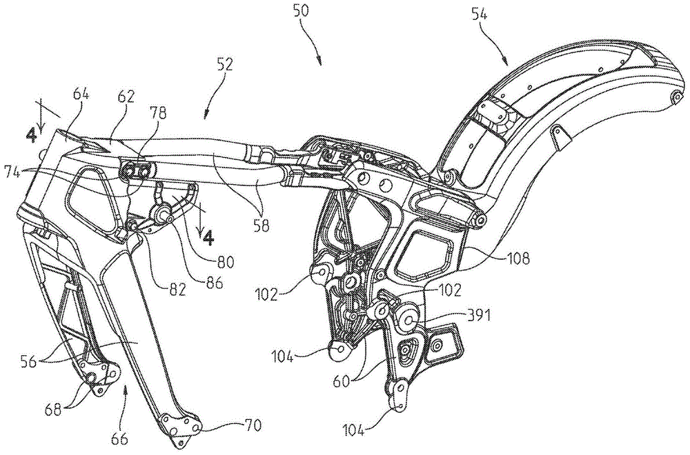
车辆2还包括车架组件50,该车架组件50用于支承动力传动系组件130、冷却组件240、燃料箱330、后悬架组件380以及操作者座椅28。现在参照图1至图4,车架组件50为模块化组件,该车架组件50包括前车架52、中间车架53和后车架54。由于车架组件50是模块化的,因此车辆2的各种部件——例如进气组件300、排气组件360、冷却组件240、操作者控制器26、转向组件24、座椅28、前悬架组件20以及后悬架组件380——可以用替代性实施方式代替,而不需要重新构造车架组件50来支承这些替代性实施方式。另外,前车架52、中间车架53和后车架54通常联接在一起,并且在不需要热处理或永久性联接件(即,焊接件)的情况下与车辆2的其他部件联接。因此,车辆2的各种部件可以用替代性部件代替,而不需要新的车架组件。The vehicle 2 also includes a
前车架52定位在中间车架53和后车架54的前方,并且前车架52包括下管构件或前臂构件56和车架横梁58。中间车架53包括侧部构件60并且中间车架53联接至前车架52和后车架54两者。如文中所进一步详述的,中间车架53栓接至前车架52和后车架54,这消除了对车架组件50的这些部分进行热处理并将车架组件50的这些部分永久联接在一起的需求。The
前车架52的前臂构件56从头部部分62向下延伸。另外,前臂构件56可以相对于头部部分62向后成角度。前臂构件56的下端部包括用于与动力传动系组件130联接的多个孔口68、70。前臂构件56与头部部分62配合以形成空间66,这将在文中进行进一步详述。The
头部部分62包括用于与转向组件24联接的头管64。头部部分62还包括用于与车架横梁58联接的多个孔口72(图3),这将在文中进行进一步详述。孔口72位于头部部分62的凹入部71内。前臂构件56、头部部分62和头管64可以为通过铸造方法形成的单个统一部件。替代性地,每个前臂构件56均可以与大约一半的头部62以及大约一半的头管64一体地形成。这些相对的侧部可以借助于常规紧固件(例如,螺栓、铆钉、焊接件和/或粘合剂)彼此联接。说明性地,前臂构件56、头部62和头管64可以由金属材料——例如铝或铬钼材料——构成。可以理解的是,前臂构件56、头部部分62和头管64的统一结构消除了对前车架52进行热处理的需求。The
车架横梁58从头部部分62向后延伸并且车架横梁58限定了车辆2的支柱。车架横梁58可以由钢构成并允许调节前车架52的刚度,并且车架横梁58还有足够的挠性,以在组装期间适应车架组件50中的各种公差和力。更具体地,车架横梁58允许动力传动系组件130在不需要向车架组件50施加预应力的情况下联接至车架组件50。另外,由于车架横梁58的使用,在将车辆2的各种部件与车架组件50组装在一起时可以不需要间隔件或其他调节件。车架横梁58的前端部包括前联接器78。前联接器78可以是焊接至车架横梁58的铸造部。替代性地,前联接器78可以借助于紧固件(例如,螺栓、铆钉)联接至车架横梁58。如图4中最佳地示出的,前联接器78可以在联接至车架横梁58时部分地延伸到该车架横梁58中。The
车架横梁58还可以包括从其向下延伸的板80。板80可以提高前车架52的强度和刚度。说明性地,如图4中所示,板80从车架横梁58向外延伸。板80包括柱86和隔离器88(图5),这将在文中进行进一步详述。板80联接至车架横梁58的一部分以及前联接器78的一部分。例如,板80可以通过焊接而一体地联接至车架横梁58和前联接器78。替代性地,板80可以借助于机械紧固件(例如,螺栓、铆钉)联接至车架横梁58和前联接器78。The
参照图3和图4,车架横梁58借助于紧固件74、76来联接至头部部分62。更具体地,前联接器78定位在头部部分62的凹入部71内,使得前联接器78与头部部分62大致平齐。紧固件74延伸穿过前联接器78的孔口79和头部部分62的孔口72。说明性地,紧固件74在车辆2的左侧上进入头部部分62并且完全延伸穿过头部部分62,以在车辆2的右侧上与紧固件76联接。在一个实施方式中,销钉或间隔件90可以定位在联接器78的孔口79内,以适应前车架52中的变化的公差。替代性地,前车架52可以不包括销钉90。在紧固件82穿过板80中的孔口83和头部部分62中的孔口84而被接纳时板80也联接至头部部分62。如图3和图4中所示,紧固件82定位在紧固件74、76下方。车架横梁58和板80与头部部分62的构型和联接消除了对前车架52进行热处理的需求。Referring to FIGS. 3 and 4 , the
车架横梁58的后端部可以说明性地包括后联接器92,该后联接器92可以是焊接至车架横梁58的铸造部。替代性地,后联接器92可以借助于诸如螺栓或铆钉之类的紧固件联接至车架横梁58。如图3和图5中所示,后联接器92包括平面部94和直立部96。平面部94从直立部96横向向外延伸并直接联接至车架横梁58。直立部96包括用于将车架横梁58联接至中间车架53的侧部构件60的多个孔口98。更具体地,紧固件106穿过孔口98和侧部构件60的孔口100而被接纳,以将侧部构件60联接至车架横梁58。The rear end portion of the
直立部96还包括用于与支承组件116联接的多个孔口99,如图5中所示。支承组件116包括板118和支架120,其中,该板118具有多个孔口119,该支架120具有凸缘122。凸缘122包括孔口124。板118定位在支架120的上方,并且紧固件126穿过板118的孔口119、凸缘122的孔口124、以及后联接器92的直立部96的孔口99而被接纳。由此,支承组件116联接至后联接器92。The
中间车架53包括从车架横梁58向下延伸的侧部构件60。如图1至图3以及图6中所示,侧部构件60还从前车架52的车架横梁58向外延伸。侧部构件60包括用于与动力传动系组件130联接的多个孔口102、104,这将在文中进行进一步详述。说明性地,侧部构件60通过铸造方法形成。
如图3中所示,侧部构件60还包括用于与后车架54联接的后接合部108。后车架54包括前接合部110,该前接合部110与侧部构件60的后接合部108互补并且该前接合部110借助于多个紧固件114联接至侧部构件60的后接合部108。紧固件114延伸穿过后车架54的前接合部110的孔口112并进入到侧部构件60的后接合部108上的孔口中。说明性地,存在有用于将后车架54联接至侧部构件60的四个紧固件114。如图3中所示,紧固件114沿纵向方向(即,大致平行于中心线)延伸。As shown in FIG. 3 , the
现在参照图6,动力传动系组件130联接至车架组件50的前车架52。如本文中所详述的,动力传动系组件130是车辆2的结构构件并将前车架52沿着车辆2的下部分联接至中间车架53。动力传动系组件130包括发动机132和变速器138。在一个实施方式中,发动机132和变速器138为一体的动力传动系单元。说明性地,发动机132为具有以可操作的方式联接至曲轴箱136的两个气缸的V型双发动机。气缸和对应的气缸盖可以不包括用于冷却的散热片,并且因此,发动机132可以是流体联接至冷却组件240的液冷式发动机,这将在文中进行进一步详述。关于发动机132和变速器138的其他细节在于2013年3月15日提交的、代理人案号为No.PLR-05-25844.01P的共同待决的美国临时专利申请序列号No.61/801,033中被公开,上述共同待决的美国临时专利申请的完整的公开内容通过参引明确地并入本文。Referring now to FIG. 6 , the
曲轴箱136的前端部和曲轴箱136的后端部都联接至车架组件50,然而,气缸不直接联接至车架组件50。曲轴箱136包括用于与前车架52和中间车架53联接的多个凸出部140。在一个实施方式中,只有曲轴箱136直接联接至前车架52和中间车架53。以此方式,曲轴箱136可以承受中间车架53和前车架52的底部部分中的负荷。另外,车架横梁58可以用于承受前车架52的顶部部分中的负荷。Both the front end of
曲轴箱136的前端部包括凸出部140,所述凸出部140与前臂构件56的下端部联接。如图6中所示,紧固件142延伸穿过前臂构件56中的孔口70以及凸出部140,以将动力传动系组件130的前端部支承在前车架52上。紧固件142还可以延伸穿过间隔件144和/或定位销钉146。间隔件144可以用于将动力传动系组件130定位在前车架52上。例如,如图6中所示,间隔件144联接至车辆2的右侧上的前臂构件56的内表面。然而,车辆2的左侧上的前臂构件56可以不包括间隔件144。因此,动力传动系组件130可以在前车架52内通过间隔件144向左移动。定位销钉146可以定位在孔口70内,以适应紧固件142与前臂构件56之间的变化的公差。The front end of the
曲轴箱136的后端部通过侧部构件60联接至中间车架53。以此方式,曲轴箱136为车辆2的结构部件并将前车架52和中间车架53的下部分联接在一起。如图6中所示,紧固件148穿过侧部构件60的孔口102和104而被接纳。紧固件148延伸穿过间隔件144并进入到曲轴箱136的凸出部140中。说明性地,间隔件144定位在曲轴箱136的右侧上,使得动力传动系组件130在车架组件50中向左移动。紧固件还可以延伸穿过定位销钉146,所述定位销钉146可以定位在侧部构件60的孔口102和孔口104内。定位销钉146可以适应紧固件142与侧部构件60之间的变化的公差。紧固件149与紧固件148联接以将曲轴箱136的后端部紧固至侧部构件60。The rear end of
车架横梁58定位在动力传动系组件130上方,并且车架横梁58可以从前车架52和中间车架53移除以便组装及维修动力传动系组件130。例如,火花塞可以从气缸的头部的中心延伸或者可以成角度地定位在气缸的头部上。因此,通过移除车架横梁58,火花塞和动力传动系组件130的其他部件(例如,气缸74)可以在不需要使动力传动系组件130与车架组件50断开联接的情况下进行修理或替换。换句话说,动力传动系组件130不需要“脱离”车架组件50以进行修理或养护。另外,由于易于接近动力传动系组件130的各部分,因此动力传动系组件130可以在车架组件50上定位在低处,从而降低了车辆2的重心。可以理解的是,燃料箱330和座椅28被移除以便接近动力传动系组件130。另外,至少一个车架横梁58可以被移除以便接近动力传动系组件130。
如图6和图7中所示,两轮车辆2可以包括联接至曲轴箱136和/或侧部构件60的侧脚架组件150。在一个实施方式中,侧脚架组件150在三个位置中联接至曲轴箱136和/或侧部构件60。说明性地,侧脚架组件150包括基部构件152、杆臂154和脚部构件156。基部构件152借助于枢转销157联接至杆臂154并借助于紧固件158联接至曲轴箱136。更具体地,紧固件158延伸穿过中间车架53的侧部构件60的孔口105,以使侧脚架组件150与车架组件50联接。另外,侧脚架组件150可以借助于延伸穿过侧部构件60的孔口104的紧固件148联接至侧部构件60。替代性地,侧脚架组件150可以联接至从动力传动系组件130的曲轴箱136延伸的紧固件159。在另一实施方式中,侧脚架组件150可以邻近曲轴箱136的前端部以进一步提高车辆2的稳定性。As shown in FIGS. 6 and 7 , the two-wheeled vehicle 2 may include a
在操作中,杆臂154可以绕枢转销157旋转,以将脚部构件156抵靠地面定位。以此方式,车辆2借助于侧脚架组件150支承在地面上。当车辆2运行时,杆臂154可以绕枢转销157枢转至图7中所示的位置,使得侧脚架组件150不与地面相碰。In operation, the
在一个实施方式中,侧脚架组件150包括传感器构件166。传感器构件166可以向车辆2的电气系统(例如,发动机控制单元(“ECU”)或车辆控制单元(“VCU”))发送信号,以表明车辆2是未操作的以及/或者车辆2正倚靠在侧脚架组件150上。因此,ECU和/或VCU可以在侧脚架组件150接合时向车辆2的其他部件发信号。In one embodiment, the
现在参照图8和图9,侧部构件60的后端部支承动力传动系组件130的后端部。如所示,制动组件12的防抱死制动模块160、以可操作的方式联接至燃料箱330的放泄阀162、以可操作的方式联接至燃料箱330的蒸发器罐164、以及电气系统的电压调节器168支承在侧部构件60的后端部处。放泄阀162和蒸发器罐164设置成用于消除来自燃料管线中的空气和水。可以理解的是,防抱死制动系统模块160、驱除阀162、蒸发器罐164以及电压调节器168定位在后悬架组件380的摆臂382下方。Referring now to FIGS. 8 and 9 , the rear end of the
如图8和图9中所示,支承板170包括第一开口172,该第一开口172具有在其中延伸的悬臂173。支承板170还包括第二开口174,该第二开口174定位在第一开口172的前方并且比第一开口172大。可以包括第一开口172、第二开口174,以用于冷却防抱死制动系统模块160、放泄阀162、蒸发器罐164以及/或者电压调节器168。支承板170还包括用于借助于紧固件202联接至防抱死制动模块160的上突部178、以及用于借助于紧固件196联接至支承基部180的多个下突部176。As shown in FIGS. 8 and 9 , the
支承基部180包括开口182。直立突部188从开口182的相对侧向上延伸。支承板170的下突部176与支承基部180的直立突部188对准,并且支承板170的下突部176借助于紧固件194和196联接至支承基部180的直立突部188。说明性地,紧固件196是螺栓并且紧固件194是焊接螺母。紧固件194、196的替代性实施方式可以用于将支承板170联接至支承基部180。The
另外,支承基部180包括前臂186和后臂184。前臂186借助于紧固件190将支承基部180联接至侧部构件60。更具体地,紧固件190延伸穿过侧部构件60中的孔口107并且紧固件190与前臂186上的内部紧固件——说明性地为焊接螺母192——联接。类似地,紧固件208将支承基部180的后臂184联接至侧部构件60。如图9中所示,侧部构件60的后端部包括具有孔口206的突部204。紧固件208延伸穿过突部204中的孔口206并且紧固件208与后臂184上的紧固件——说明性地为焊接螺母192——联接。Additionally, the
支承板170和支承基部180两者都定位在侧部构件60之间,使得防抱死制动系统模块160、放泄阀162、蒸发器罐164和电压调节器168也大致支承在侧部构件60之间。在一个实施方式中,电压调节器168联接至支承基部180的下侧部并在侧部构件60下方延伸。以此方式,电压调节器168定位在后悬架组件380的摆臂382下方,以便用于对流经电压调节器168的空气进行冷却。类似地,蒸发器罐164可以借助于紧固件198和紧固件200联接至支承板170的下侧部,并且蒸发器罐164也在侧部构件60下方延伸。如所示,蒸发器罐164可以包括支架165以用于联接至支承板170。Both the
放泄阀162和防抱死制动系统模块160可以支承在支承板170和支承基部180上方。例如,放泄阀162可以包括狭槽163,该狭槽163接纳支承板170的悬臂173。以此方式,放泄阀162可以在支承板170的第一开口172内滑动到悬臂173上。另外,防抱死制动系统模块160借助于紧固件202联接至上突部178并且防抱死制动系统模块160大致定位在第二开口174上方。Dump
参照图10和图11,中间车架53的侧部构件60的上部分支承用于至少一个电池以及电气系统的其他部件(诸如控制模块、螺线管和熔断器之类)的外罩210。另外,外罩210可以支承冷却剂瓶230。座椅28(图24)可以定位在外罩210和冷却剂瓶230上方。冷却剂瓶230邻近动力传动系组件130定位,并且冷却剂瓶230暴露于由动力传动系组件130产生的热。因此,冷却剂瓶230由构造成经受动力传动系组件130的热的材料构成。在一个实施方式中,冷却剂瓶230由尼龙填充的材料构成。10 and 11, upper portions of
冷却剂瓶230还是不透明的并且可以是黑色的。以此方式,由外罩210支承的各种电气部件被隐藏,从而提高了车辆2的美观性。然而,由于冷却剂瓶230是不透明的,因此冷却剂瓶230内的流体会是不可见的。因此,冷却剂瓶230包括透明观察线234,该透明观察线234允许操作者看到冷却剂瓶230内的流体的液面。替代性地,冷却剂瓶230的前表面可以是不透明的,并且后表面可以是透明的以允许操作者看到冷却剂瓶230中的流体。另外,冷却剂瓶230包括螺纹接头236、238,螺纹接头236、238构造成接纳冷却剂管线,以使冷却剂流体从冷却剂瓶230流动。冷却剂管线(未示出)可以是透明的。另外,说明性的冷却剂瓶230包括盖231,然而,冷却剂瓶230的替代性实施方式可以包括塞子。塞子可以构造成接纳漏斗,以有助于倒入到冷却剂瓶230中的额外的冷却剂的流动。The
如图11中最佳地示出的,板226可以联接至冷却剂瓶230的后侧部,以将冷却剂瓶230支承在外罩210上。更具体地,板226可以包括孔口228,所述孔口228与外罩210上的孔口224对准并接纳穿过孔口228和孔口224的紧固件225(图10)。As best shown in FIG. 11 , the
外罩210背离动力传动系组件130,并且外罩210包括具有多个开口212的侧壁211、前臂213和底壁214。紧固件222可以穿过侧壁211的孔口218以及侧部构件60的孔口220而被接纳,以便将外罩210联接至中间车架53。至少一个电池可以定位在外罩210内,并且更具体地,电池可以由底壁214支承并通过从底壁214向上延伸的唇缘部216紧固。另外,电池可以定位在侧壁211与前壁213的后部之间。侧壁211中的开口212允许由电池产生的任何热从外罩210逸出。车辆2的电气系统的其他部件可以支承在侧壁211和底壁214的外表面上。The
现在参照图12至图15,冷却组件240包括散热器242、定位在散热器242后方的风扇244、以及定位在散热器242下端部处的护罩246。在一个实施方式中,冷却组件240包括以可操作的方式联接至动力传动系组件130以对发动机132进行液体冷却的泵。冷却组件240的其他细节在于2013年3月15日提交的、代理人案号为No.PLR-05-25844.01P的共同待决的美国临时专利申请序列号No.61/801,033中被公开,上述共同待决的美国临时专利申请的完整的公开内容通过参引明确地并入本文。Referring now to FIGS. 12-15 , the cooling
说明性的散热器242包括多个竖直散热片243。冷却组件240支承在前车架52的前臂构件56上。更具体地,冷却组件240支承在前车架52的空间66内,使得头部部分62和前臂构件56大致围绕冷却组件240。冷却组件240在动力传动系组件130前方并邻近发动机132。通过将冷却组件240定位成靠近动力传动系组件130,车辆2的轴距可以减小。The
如图12和图13中所示,护罩246围绕散热器242的下端部并定位在风扇244下方。护罩246可以促进空气流入到冷却组件240中。护罩246借助于紧固件252联接至前臂构件56。更具体地,紧固件252延伸穿过护罩246中的孔口248以及前臂构件56的下端部中的孔口254。紧固件252与沿着护罩246的内表面的紧固件250联接。As shown in FIGS. 12 and 13 , the
散热器242的下端部借助于紧固件256联接至前臂构件56的下端部。如图13中所示,前臂构件56的孔口262与散热器242上的突部268中的孔口266对准。因此,紧固件256可以延伸穿过套筒258、衬套260和衬套264、以及孔口262和孔口266,以与紧固件270(例如,焊接螺母)联接并将冷却组件240紧固至前车架52。衬套260和衬套264可以由例如橡胶的聚合物材料构成,以使冷却组件240不受振动影响。The lower end of the
如图14和图15中所示,冷却组件240的上端部包括联接至护罩246的车架结构272。说明性地,车架结构272可以一体地联接至护罩246。冷却组件240还包括用于将车架结构272联接至前车架52的支架276。支架276可以由例如橡胶的聚合物材料构成,并且支架276可以使冷却组件240不受振动影响。支架276可以联接至前车架52的前臂构件56和/或头部部分62。如图14中所示,车架结构272包括突出部274,突出部274接纳在支架276的孔口278内。当突出部274延伸到孔口278中时,车架结构272的一部分接纳在支架276的凹入部277内。支架276还包括用于接纳从散热器242横向延伸的柱280的孔口282。以此方式,支架276联接至散热器242和车架结构272两者,以将冷却组件240联接至前车架52。As shown in FIGS. 14 and 15 , the upper end of the cooling
可以理解的是,仅冷却组件240的下端部直接联接至前车架52。冷却组件240的上端部借助于支架276紧固在前车架52内。以此方式,冷却组件240可以在其下端部处与前车架52断开联接并构造成沿向下方向和/或向前方向滑动、枢转或以其他方式移动,以接近动力传动系组件130。例如,冷却组件240可以绕套筒258枢转,以使散热器242远离动力传动系组件130移动。在另一实施方式中,冷却组件240可以在向下方向上沿着前臂构件56滑动,以使散热器242远离动力系组件130移动。由此,冷却组件240被容易地从车辆2中移除,以便在不需要使动力传动系组件130与车架组件50断开联接的情况下接近动力传动系组件130以进行修理和养护。It will be appreciated that only the lower end of the cooling
参照图16至图19,进气组件300包括气箱302和积储器空间324。另外,在一个实施方式中,流过进气组件300的空气可以通过压力装置增压。进气组件300定位在燃料箱330下方并支承在前车架52的车架横梁58上,这将在文中进行进一步详述。气箱302的一部分在前车架52的车架横梁58上方延伸,并且气箱302的一部分在车架横梁58下方延伸以与节气门本体321联接。进气组件还定位在前车架52的头部部分62的后方。Referring to FIGS. 16-19 , the
说明性地,气箱302包括过滤器304、托盘306和基部308。托盘306静置在基部308的嵌入表面319的顶部。过滤器304定位在托盘306上方。过滤器304借助于接纳在基部308的孔口318内的紧固件316联接至基部308。如图18和图19中所示,托盘306向下成角度地进入到基部308中,使得进入托盘306的空气被朝向积储器空间324引导。积储器空间324限定在前车架52的头部部分62内。说明性地,积储器空间324定位在头管64的后方。头部部分62中的开口325接合基部308的积储器出口310上的密封件314。积储器空间324通过形成了用于空气进入气箱302的额外或辅助空气容积而增大了气箱302的尺寸。Illustratively,
基部308借助于密封件314和夹具312密封地联接至前车架52的头部部分62。另外,基部308包括节气门本体出口328,该节气门本体出口328借助于密封件320密封地联接至节气门本体321。节气门本体321包括出口端口322,并且节气门本体321还可以包括以可操作的方式联接至该节气门本体321的电子节气门控制(“ETC”)致动器323。出口端口322在气箱302下方和车架横梁58下方延伸,以便向发动机132的两个气缸提供空气。The
基部308的侧表面包括用于接纳隔离器326的凹入部327。隔离器326可以由例如橡胶的聚合物材料构成,以用于使进气组件300不受振动影响。此外,隔离器326的轮廓构造为在基部308的凹入部327内延伸并绕车架横梁58延伸。因此,进气组件300定位在车架横梁58之间并借助于隔离器326紧固至车架横梁58。另外,进气组件300定位在燃料箱330与节气门本体321之间。说明性地,进气组件300不借助于任何紧固件来联接至车架组件50,而是以摩擦的方式保持在车架横梁58、燃料箱330与节气门本体321之间。为了从车辆2接近进气组件300以及/或者将进气组件300从车辆2中移除,可以暂时地将一个车架横梁58从车架组件50移除,以便将气箱302从车架组件50移除。The side surfaces of
当车辆2正运行时,周围空气在燃料箱330下方流动并进入到进气组件300中。更具体地,周围空气流入到气箱302的过滤器304中,在过滤器304中,污物、杂物和其他颗粒物质被从周围空气中过滤掉,使得气箱302中的空气是“洁净”空气。在一个实施方案中,过滤器304由半多孔的可模制泡沫材料构成,该半多孔的可模制泡沫材料可以构造成将空气吸入到过滤器304中并穿过过滤器304。洁净空气然后沿着托盘306流动并进入到基部308中。基部308中的一部分空气流入到节气门本体出口328中、穿过节气门端口322并进入到发动机132中。另外,基部308中的一部分洁净空气朝向积储器出口310流动并进入到积储器空间324中。托盘306的构型和角度可以有助于空气流入到积储器空间324中。随着气箱302和积储器空间324中的空气体积增大,发动机132的性能可以被改进(例如,节气门本体321能够获得的额外空气可以增大动力传动系组件130的功率)。以此方式,可以增加能够由具有小于62英寸的轴距的车辆上的发动机132获得的空气。When the vehicle 2 is running, ambient air flows under the
来自动力传动系组件130的气体穿过排气组件而从车辆2排出。排气组件为沿着车辆2的右侧布置的双排气系统。替代性地,排气组件可以是由单个排气管构成的单排气系统。Gases from the
参照图20至图23,燃料箱330联接至前车架52,并且燃料箱330说明性地定位在头部部分62的后方和中间车架53的前方。燃料箱330定位在进气组件300和车架横梁58上方。如图20中最佳地示出的,燃料箱330具有位于前车架52上的低轮廓并且燃料箱330在后端部处向下成角度。Referring to FIGS. 20-23 ,
如图21中所示,燃料箱330联接至支架120(也在图5中示出)的一部分。更具体地,支承板332在后端部处联接至燃料箱330的的底表面。在一个实施方式中,支承板332可以由刚性的聚合物材料构成。支架334包括唇缘部335和多个孔口336。紧固件348将支架334联接至燃料箱330的后端部处的支承板332。另外,联接构件338包括钩挂构件339和多个孔口340。联接构件338的孔口340与支架120的孔口342对准,以接纳穿过孔口340和孔口342的衬套344和紧固件346。紧固件346还延伸穿过支架334的一部分,以确保将联接构件338和支架120联接至燃料箱330的支承板332。另外,钩挂构件339与支架334的唇缘部335联接,以进一步地将联接构件338保持至支架334。说明性地,联接构件338在与支架334组装在一起时定位在支架334下方。以这种方式,燃料箱330通过支架120联接至前车架52并且燃料箱330定位在板118的前方(图20)。支架334和/或联接构件338可以由聚合物材料构成以使燃料箱330不受振动影响。As shown in FIG. 21 , the
另外,燃料箱330的前端部安装至前车架52的头部部分62。更具体地,如图21中所示,燃料箱330的下侧部包括用于接纳头部部分62上的隔离器88和柱86(图5)的联接器349。隔离器88接纳在柱86上并支承在联接器349上。由于隔离器88由聚合物材料构成,因此隔离器88可以使燃料箱330不受振动影响。In addition, the front end portion of the
燃料泵组件350在燃料箱330的后端部处支承在支承板332上,如图22和图23中所示。另外,通过将燃料泵组件350定位在燃料箱330的后部处,可以保持燃料箱330在前车架52上的低轮廓。燃料泵组件350包括泵352和拾取式过滤器或筛网354。筛网354可以借助于臂356联接至泵352。因此,燃料通过筛网354被吸入到泵352中。燃料在流入到泵352中之前在筛网354中进行过滤。The
燃料箱330的成角度的构型允许燃料从燃料箱330的前端部向后并朝向燃料泵352流动至后端部。然而,为了避免在燃料向后流动时的后溅,沿着燃料的流动路径在燃料箱330内定位有后防溅板358。说明性地,后防溅板358定位在泵352和筛网354的前方。因此,后防溅板358总体上调节燃料在燃料箱330内的流动。另外,如果车辆2在操作期间沿向前方向倾斜(例如,车辆2处于下坡位置),则后防溅板358防止位于燃料箱330的后端部处的燃料向前朝向燃料箱330的前端部快速地流动。在没有后防溅板358的情况下,燃料泵352可能在车辆2下坡移动时缺乏燃料。The angled configuration of the
如图24中所示,座椅28包括第一座椅部28a和第二座椅部28b。第一座椅部28a和第二座椅部28b可以一体地联接在一起。替代性地,第一座椅部28a和第二座椅部28b可以彼此分开。第一座椅部28a限定了用于车辆2的操作者的座椅底部。第二座椅部28b可以构造为乘客座椅底部或用于操作者的靠背部。在车辆2的一个实施方式中,第二座椅部28b可以被移除以使得车辆2仅包括第一座椅部28a。As shown in FIG. 24, the
支承板370定位在第一座椅部28a下方,并且支承板370包括具有孔口373的突部372。孔口373与板118中的孔口366对准,并且紧固件368延伸穿过孔口373和孔口366,以将座椅28与中间车架53联接。如图24中所示,座椅28支承在中间车架53的侧部构件60上方并定位在燃料箱330(图20)后方。The
第二座椅部28b包括支承板370,该支承板370具有闩锁构件374和多个橡胶缓冲器376。橡胶缓冲器376构造成使座椅28不受振动影响。闩锁构件374接纳在联接至后挡泥板400的板378的开口379内。以此方式,座椅28通过板118联接至中间车架53,并且座椅28借助于闩锁构件374联接至后挡泥板400。The
现在参考图25至图28,后车架54被示出。后车架54联接至中间车架53,并且更具体地联接至侧部构件60。后挡泥板400借助于紧固件402和紧固件404联接至后车架54。说明性地,四个紧固件402和四个紧固件404经由后挡泥板400上的孔口414以及后车架54上的孔口416来将后挡泥板400联接至后车架54。后挡泥板400的形状大致对应于后车架54的形状。另外,座椅安装板378在后车架54上的位置保持了座椅28的低位置并有助于降低车辆2的重心。后车架54还可以包括借助于紧固件396联接至后车架54的防护板394。防护板收集可能被甩出后轮10的污物、泥和其他碎屑。Referring now to FIGS. 25-28 , the
后挡泥板400还包括用于接纳后照明组件462的开口406。如图28中所示,后照明组件462包括安装板419,该安装板419支承尾灯420、右侧转向信号灯424、左侧转向信号灯426、牌照灯422以及后反射器428。安装板419和/或尾灯420还可以支承用于操作尾灯420、转向信号灯424和转向信号灯426以及牌照灯422的电线的线束。在图28的说明性实施方式中,尾灯420用作用以支承尾灯420、转向信号灯424和转向信号灯426以及牌照灯422的布线的接线盒。后挡泥板400还可以构造成支承鞍袋或其他货运装置。The
现在参照图26和图27,说明性的后挡泥板400的前端部可能是非对称的。更确切地,后挡泥板400的右前侧部408比左前侧部410长。右前侧部408构造成接触摆臂382,并且更具体地,右前侧部408构造成接触位于摆臂382的前横向构件460处的凹入部412。后挡泥板400的左前侧部410被压型并在其中包括凹口411。横向构件460的凹入部412位于后悬架组件380的枢转轴430后方,并且横向构件460的凹入部412接纳后挡泥板400的右前侧部408。因此,当车辆2被从右侧部观察时,后挡泥板400看起来连续地延伸到摆臂382中。Referring now to FIGS. 26 and 27 , the front end of the illustrative
后悬架组件380联接至中间车架53并部分地绕后挡泥板400延伸。后悬架组件380包括通过前横向构件460联接在一起的一对摆臂382。另外,后悬架组件380包括联接至摆臂382和车架组件50的一对减震装置384。更具体地,并且如图26A中所示,减震装置384的上端部借助于紧固件388联接至中间车架53的侧部构件60的孔口392。另外,减震装置384的下端部联接至摆臂382上的孔口387。如图25中所示,减震装置384相对于摆臂382成角度以提供“硬尾”外观,然而,减震装置384构造成即使在处于该角度的情况下仍承载悬架载荷。替代性地,减震装置384’可以联接至后车架54,如图26B中所示。在一个实施方式中,支架385可以用于将减震装置384’支承在后车架54的前端部上。因此,减震装置384’相对于摆臂382的角度可以比图26A的减震装置384相对于摆臂382的角度大。The
与减震装置384一样,摆臂382也联接至中间车架53的侧部构件60。更具体地,摆臂382的前端部联接至侧部构件60的孔口391(图1)。枢转轴430在侧部构件60之间延伸并且枢转轴430在其中接纳有紧固件390。如图29至图31中所示,摆臂382的前端部包括用于与枢转轴430联接的孔口387。另外,紧固件390、带凸缘的间隔件432、第一垫圈434、夹子436、第一轴承438、第二轴承440、第一密封件442、第三轴承444、第二密封件446、第二垫圈448以及紧固件449用于将枢转轴支承在摆臂382上。如图30中所示,枢转轴430包括螺纹端部450,该螺纹端部450具有内部压型表面452。枢转轴430的圆筒形孔口454在枢转轴430的外端部之间延伸。Like the
如图30中所示,枢转轴430的内部压型表面452可以与例如扳手的工具接合,以在摆臂382联接至侧部构件60时调节侧部构件60之间的间距。更具体地,摆臂382之间的间距是固定的,这是因为前横向构件460限定了摆臂382之间的距离。然而,由于车架横梁58的挠性,侧部构件60可以向内或向外移动以调节摆臂382的位置。换句话说,侧部构件60构造成吸收侧部构件60与摆臂382之间的公差。在操作中,如图29中所示,位于车辆2的右侧部上的侧部构件60的孔口391包括内螺纹以用于与枢转轴430的螺纹端部450接合。因此,枢转轴430与孔口391螺纹接合。工具可以定位成抵靠内部压型表面452,以使枢转轴430进一步地从孔口391旋转或使枢转轴430在孔口391内向外旋转。以这种方式,侧部构件60之间的距离可以适应摆臂382的大小和位置。As shown in FIG. 30 , the
在枢转轴430位于适当位置的情况下,紧固件390可以插入穿过枢转轴430的圆筒形孔口454,以将摆臂382联接至侧部构件60。如图31中所示,左侧摆臂382的孔口387可以包括垫圈434、夹子436、第一轴承438和第二轴承440以及带凸缘的间隔件432。说明性地,第一轴承438和第二轴承440是球轴承。紧固件390延伸穿过左侧摆臂382上的孔口387以及穿过垫圈434、夹子436、第一轴承438和第二轴承440以及带凸缘的间隔件432中的孔口,以便延伸穿过枢转轴430的圆筒形孔口454。紧固件390还延伸穿过右侧摆臂382上的孔口387以及穿过带凸缘的间隔件432、密封件442、轴承444、密封件446、垫圈448的孔口,并且紧固件390联接至紧固件449。说明性地,轴承444为滚针轴承,并且紧固件449为螺母。以此方式,摆臂382联接至侧部构件60。With
摆臂382构造成在车辆2的操作期间绕枢转轴430枢转。另外,紧固件390、带凸缘的间隔件432、第一垫圈434、夹子436、第一轴承438、第二轴承440、第一密封件442、第三轴承444、第二密封件446、第二垫圈448以及紧固件449的布置形成了右侧摆臂382上的“浮动”侧和左侧摆臂382上的“固定”侧。更具体地,由于轴承444是滚针轴承,因此在孔口387内允许进行一些受限运动,并且因此,限定了“浮动”侧。相反地,轴承438、440是固定在孔口387内的单列球轴承,并且因此,限定了“固定”侧。在低扭矩的状态下,枢转轴430接触车辆2的左侧部上的侧部构件60,这是因为枢转轴430构造成沿着轴承444向左滑动。The
参照图32,乘客脚蹬组件456包括脚踏构件457和盖构件458。脚踏构件457联接至盖构件458,该盖构件458定位在用于摆臂382的紧固件390上方。更具体地,紧固件459联接至摆臂382上的孔口455,以将盖构件458和脚踏构件457联接至摆臂382。Referring to FIG. 32 , the
如图33中所示,车辆2包括以可操作的方式联接至动力传动系组件130的带驱动组件。该皮带驱动组件包括从动轮476和带478。带478由动力传动系组件130驱动并且带478对轮476进行驱动,以便在操作车辆2时使后轴480和后轮10旋转。如图33中所示,带478可以足够窄,以配装在轮476的轮缘内。说明性地,轮476定位在左侧摆臂382的内侧。As shown in FIG. 33 , vehicle 2 includes a belt drive assembly operably coupled to
如图33和图34中所示,后轴480上包括后轴调节构件470,并且后轴调节构件470借助于摆臂382与后轴480联接。更具体地,调节构件470的头部471定位在摆臂382的后端部内,并且柱472联接至头部471。柱472延伸穿过摆臂382的后孔口479并借助于紧固件477紧固在摆臂382上。As shown in FIGS. 33 and 34 , the
后轴480的外端部延伸穿过头部471中的开口并部分地位于摆臂382的外侧。具有多个狭槽482的狭槽板473接纳在后轴480上,并且适当的狭槽482与摆臂382上的狭槽484对准。狭槽板473的位置借助于螺母474和延伸穿过后轴480的孔口486的销475来保持。相对的摆臂382上的相对的狭槽板473上的相同的狭槽482与摆臂382上的狭槽484对准,以便将后轴480和后轮10以适当对准的方式紧固在摆臂382上。The outer end of the
参照图35和图36,车辆2的前端部4包括转向组件24、控制器26和把手30。把手30可以借助于支架500安装在三重夹具组件32上,该支架可以联接至操作者计量器502。以此方式,操作者计量器502的一部分可以与三重夹具组件32配合以安装把手30。紧固件504延伸穿过支架500中的孔口并进入到三重夹具组件32的上部分36上的支承构件506中的孔口中。因此,把手30通过三重夹具组件32支承在车辆2上。三重夹具组件32的上部分36借助于紧固件35联接至头部部分62,并且借助于紧固件38联接至叉状构件34。三重夹具组件32还包括借助于孔口39绕叉状构件34联接的下部构件37。Referring to FIGS. 35 and 36 , the front end 4 of the vehicle 2 includes a
操作者计量器502朝向座椅28中的操作者向后成角度,并且操作者计量器502可以用作护罩。因此,车辆2的前端部4处不需要额外的护罩或盖。在一个实施方式中,操作者计量器502在把手30的轴线的后方安装。The
替代性地,如图37中所示,把手30’可以借助于支架500’和支承构件506’联接至三重夹具组件32’的上部分36’。然而,操作者计量器502’可以定位在把手30’的轴线的前方。以此方式,三重夹具组件32’可以将把手30’安装至车辆2,然而,操作者计量器502’不是由把手30’一体地支承。Alternatively, as shown in Figure 37, handle 30' may be coupled to upper portion 36' of triple clamp assembly 32' by means of bracket 500' and support member 506'. However, operator gauge 502' may be positioned forward of the axis of handle 30'. In this manner, the triple clamp assembly 32' may mount the handle 30' to the vehicle 2, however, the operator gauge 502' is not integrally supported by the handle 30'.
把手30包括镜子514和杆516。杆516可以是用于操作车辆2的油门杆和/或制动杆。另外,把手30可以包括额外的操作者控制器26。例如,用于车辆2的各个方面、配件和部件的电子功能可以通过按下连接至把手30上的瞬时开关的按钮来激活。在一个实施方式中,按钮被按下预定时间长度以激活电子功能。ECU构造成检测由瞬时开关输出的信号并激活适当的功能。用于使按钮移动的特定模式将通过不同的输出信号来由ECU进行识别。在一个实施方式中,在按钮上短按或轻敲将向ECU提供一个信号,而按下预定时间长度将向ECU输出另一信号。到达ECU的各种信号触发ECU来激活车辆2的各种功能。The
车辆2的前端部4还可以包括前灯510和转向信号灯508。用于前灯510和转向信号灯508的布线可以联接在前灯510的盖或斗512内。The front end 4 of the vehicle 2 may also include
尽管本发明已经被描述为具有示例性设计,但是本发明可以在本公开的精神和范围内进行进一步修改。因此,本申请意在涵盖本发明的使用其基本原理作出的任何改型、使用或修改。此外,本申请意在涵盖与本公开有偏差而属于本发明所属技术领域中的已知或惯用做法的这些应用。While this invention has been described as having an exemplary design, the present invention can be further modified within the spirit and scope of this disclosure. Accordingly, this application is intended to cover any adaptations, uses, or adaptations of this invention using its underlying principles. Furthermore, this application is intended to cover such applications as depart from this disclosure and fall within known or customary practice in the art to which this invention pertains.
Claims (12)
Applications Claiming Priority (3)
| Application Number | Priority Date | Filing Date | Title |
|---|---|---|---|
| US201361799880P | 2013-03-15 | 2013-03-15 | |
| US61/799,880 | 2013-03-15 | ||
| CN201480013298.8A CN105143028B (en) | 2013-03-15 | 2014-03-14 | two wheeled vehicle |
Related Parent Applications (1)
| Application Number | Title | Priority Date | Filing Date |
|---|---|---|---|
| CN201480013298.8A Division CN105143028B (en) | 2013-03-15 | 2014-03-14 | two wheeled vehicle |
Publications (2)
| Publication Number | Publication Date |
|---|---|
| CN108100128A CN108100128A (en) | 2018-06-01 |
| CN108100128B true CN108100128B (en) | 2020-08-21 |
Family
ID=50678299
Family Applications (3)
| Application Number | Title | Priority Date | Filing Date |
|---|---|---|---|
| CN201810044184.XA Active CN108100128B (en) | 2013-03-15 | 2014-03-14 | two wheeled vehicle |
| CN201810044175.0A Active CN108100129B (en) | 2013-03-15 | 2014-03-14 | two wheeled vehicle |
| CN201480013298.8A Active CN105143028B (en) | 2013-03-15 | 2014-03-14 | two wheeled vehicle |
Family Applications After (2)
| Application Number | Title | Priority Date | Filing Date |
|---|---|---|---|
| CN201810044175.0A Active CN108100129B (en) | 2013-03-15 | 2014-03-14 | two wheeled vehicle |
| CN201480013298.8A Active CN105143028B (en) | 2013-03-15 | 2014-03-14 | two wheeled vehicle |
Country Status (8)
| Country | Link |
|---|---|
| US (5) | US9440504B2 (en) |
| EP (2) | EP2969724B1 (en) |
| JP (1) | JP6495887B2 (en) |
| CN (3) | CN108100128B (en) |
| AU (4) | AU2014227761B2 (en) |
| BR (1) | BR112015020833A2 (en) |
| CA (1) | CA2902308A1 (en) |
| WO (1) | WO2014144224A1 (en) |
Families Citing this family (40)
| Publication number | Priority date | Publication date | Assignee | Title |
|---|---|---|---|---|
| FR2993212B1 (en) * | 2012-07-13 | 2015-11-27 | Rdmo | MOTORCYCLE WITH LIQUID COOLING ENGINE |
| US20150158542A1 (en) * | 2012-12-09 | 2015-06-11 | Jesse G. James | Vehicle engine and transmission frame |
| CN108100128B (en) | 2013-03-15 | 2020-08-21 | 北极星工业有限公司 | two wheeled vehicle |
| JP6071811B2 (en) * | 2013-09-05 | 2017-02-01 | 本田技研工業株式会社 | Saddle riding type vehicle |
| US20190276110A1 (en) * | 2014-12-29 | 2019-09-12 | Peter Tristan Ridet | System and method for dynamic motorcycle frame |
| US10336397B2 (en) | 2014-12-29 | 2019-07-02 | Peter Tristan Ridet | System and method for dynamic motorcycle frame |
| US10870465B2 (en) * | 2015-05-22 | 2020-12-22 | Polaris Industries Inc. | Power boost regulator |
| CA2986482C (en) | 2015-05-22 | 2021-07-06 | Polaris Industries Inc. | Power boost regulator |
| JP6167151B2 (en) * | 2015-10-09 | 2017-07-19 | 本田技研工業株式会社 | Saddle riding |
| JP2017105286A (en) * | 2015-12-08 | 2017-06-15 | スズキ株式会社 | Saddle riding vehicle |
| CN106005181B (en) * | 2016-06-16 | 2018-12-14 | 江苏小牛电动科技有限公司 | Oblique pull shock-damping structure is set in a kind of electric bicycle |
| CN106627913A (en) * | 2016-12-30 | 2017-05-10 | 天津福盛达运动器材有限公司 | Light and environment-friendly children bike |
| CA3055952A1 (en) * | 2017-03-10 | 2018-09-13 | Indian Motorcycle International, LLC | Two-wheeled vehicle |
| JP6489715B2 (en) * | 2017-03-27 | 2019-03-27 | 本田技研工業株式会社 | Body structure of saddle-ride type vehicle |
| JP6457000B2 (en) * | 2017-03-28 | 2019-01-23 | 本田技研工業株式会社 | Air cleaner support structure for saddle-ride type vehicles |
| US10655536B1 (en) | 2017-05-24 | 2020-05-19 | Indian Motorcycle International, LLC | Engine |
| US10589621B1 (en) * | 2017-05-24 | 2020-03-17 | Indian Motorcycle International, LLC | Two-wheeled vehicle |
| US11225290B2 (en) * | 2017-07-21 | 2022-01-18 | Polaris Industries Inc. | Vehicle |
| JP6845766B2 (en) * | 2017-08-22 | 2021-03-24 | 川崎重工業株式会社 | Saddle-type vehicle and radiator wind guide |
| DE102017217662A1 (en) | 2017-10-05 | 2019-04-11 | Bayerische Motoren Werke Aktiengesellschaft | Tank assembly on a frame of a motorcycle, frame member for a motorcycle and assembly method |
| US10760536B2 (en) | 2017-10-27 | 2020-09-01 | Indian Motorcycle International, LLC | Air box for a vehicle |
| US20190247780A1 (en) * | 2018-02-12 | 2019-08-15 | Dan Conrad | Easy change filter system For a Vehicle |
| JP7035819B2 (en) * | 2018-06-05 | 2022-03-15 | スズキ株式会社 | Canister layout structure for motorcycles |
| US11117637B2 (en) | 2018-07-25 | 2021-09-14 | Harley-Davidson Motor Company Group, LLC | Motorcycle frame |
| ES2915590T3 (en) * | 2018-09-07 | 2022-06-23 | Yamaha Motor Co Ltd | tiltable vehicle |
| USD911879S1 (en) | 2018-09-10 | 2021-03-02 | Indian Motorcycle International, LLC | Motorcycle |
| US11077910B2 (en) | 2018-09-28 | 2021-08-03 | Indian Motorcycle International, LLC | Two-wheeled vehicle |
| WO2020089947A1 (en) * | 2018-11-02 | 2020-05-07 | Hero MotoCorp Limited | Vehicle |
| US10647374B1 (en) * | 2018-12-18 | 2020-05-12 | Kawasaki Jukogyo Kabushiki Kaisha | Straddle type vehicle and rear fender |
| US12227253B2 (en) | 2019-03-22 | 2025-02-18 | Indian Motorcycle International, LLC | Two-wheeled vehicle with fairing coupled to down tube assembly |
| TW202045379A (en) * | 2019-06-06 | 2020-12-16 | 品睿綠能科技股份有限公司 | Battery compartment structure of straddle-type electric motorcycle capable of achieving the objective of integrating the battery compartment and the frame structure of the electric motorcycle |
| JP2021062724A (en) * | 2019-10-11 | 2021-04-22 | ヤマハ発動機株式会社 | Saddle-riding type vehicle |
| EP4328092B1 (en) * | 2020-02-04 | 2025-09-03 | Indian Motorcycle International, LLC | Electronic component assembly for a motorcycle |
| CN115349051A (en) * | 2020-03-31 | 2022-11-15 | Tvs电机股份有限公司 | Air filter assembly |
| CN111994194B (en) * | 2020-08-30 | 2022-05-17 | 重庆隆鑫机车有限公司 | Universal frame for motorcycle |
| CA3191191A1 (en) * | 2020-08-31 | 2022-03-03 | Christian Nolin | Method for assembling motorcycles of a family of motorcycles and corresponding motorcycles |
| CN116691894B (en) * | 2022-02-28 | 2026-01-16 | 浙江春风动力股份有限公司 | Motorcycle |
| CN116691893A (en) * | 2022-02-28 | 2023-09-05 | 浙江春风动力股份有限公司 | motorcycle |
| US12194954B2 (en) | 2023-03-17 | 2025-01-14 | Polaris Industries Inc. | Integrated seat belt energy management loop |
| IT202300016218A1 (en) * | 2023-08-01 | 2025-02-01 | Ducati Motor Holding Spa | VEHICLE WITH AT LEAST TWO WHEELS AND A FORK WITH ADJUSTABLE LATERAL STIFFNESS |
Citations (7)
| Publication number | Priority date | Publication date | Assignee | Title |
|---|---|---|---|---|
| JPS6244875Y2 (en) * | 1982-07-23 | 1987-11-28 | ||
| EP0532791A1 (en) * | 1991-09-20 | 1993-03-24 | Yamaha Hatsudoki Kabushiki Kaisha | Detachable frame for motorcycle |
| JPH0891270A (en) * | 1994-09-28 | 1996-04-09 | Suzuki Motor Corp | Frames for motorcycles |
| CN2411195Y (en) * | 2000-01-10 | 2000-12-20 | 永祺车业股份有限公司 | Combined pivot device |
| CN1747869A (en) * | 2003-02-18 | 2006-03-15 | 雅马哈发动机株式会社 | Two-wheeled motor vehicle |
| CN1749097A (en) * | 2004-09-16 | 2006-03-22 | 雅马哈发动机株式会社 | Motorcycle |
| CN1827459A (en) * | 2005-03-02 | 2006-09-06 | 本田技研工业株式会社 | Frame of an automatic two-wheeled vehicle |
Family Cites Families (225)
| Publication number | Priority date | Publication date | Assignee | Title |
|---|---|---|---|---|
| GB555975A (en) | 1942-01-06 | 1943-09-15 | Vincent H R D Company Ltd | Improvements in or relating to motorcycles |
| JPS5133624U (en) | 1974-09-04 | 1976-03-12 | ||
| JPS5128932A (en) | 1974-09-04 | 1976-03-11 | Honda Motor Co Ltd | Jidonirinshaniokeru enjinreikyakusochi |
| GB1528925A (en) | 1975-08-11 | 1978-10-18 | Hooper B | Loop driven vehicles |
| JPS558699Y2 (en) | 1975-12-05 | 1980-02-26 | ||
| JPS5277160A (en) | 1975-12-24 | 1977-06-29 | Kureha Chem Ind Co Ltd | Ethylene-vinyl alcohol copolymer compositions |
| USD254540S (en) | 1977-09-13 | 1980-03-25 | Honda Giken Kogyo Kabushiki Kaisha | Motorcycle |
| USD255559S (en) | 1977-10-21 | 1980-06-24 | Honda Giken Kogyo Kabushiki Kaisha | Motorcycle |
| US4170272A (en) * | 1978-02-23 | 1979-10-09 | Smolinski Donald E | Frame for a chopper-type motorcycle |
| USD264574S (en) | 1978-09-20 | 1982-05-25 | Kawasaki Jukogyo Kabushiki Kaisha | Motorcycle |
| USD274423S (en) | 1980-04-26 | 1984-06-26 | Yamaha Hatsudoki Kabushiki Kaisha | Motorcycle |
| USD267638S (en) | 1980-08-09 | 1983-01-18 | Yamaha Hatsudoki Kabushiki Kaisha | Motorcycle |
| USD267245S (en) | 1980-09-06 | 1982-12-14 | Yamaha Hatsudoki Kabushiki Kaisha | Motorcycle |
| USD268999S (en) | 1980-09-23 | 1983-05-17 | Honda Giken Kogyo Kabushiki Kaisha | Motorcycle |
| USD271865S (en) | 1980-10-08 | 1983-12-20 | Honda Giken Kogyo Kabushiki Kaisha | Motorcycle |
| USD272138S (en) | 1981-02-27 | 1984-01-10 | Yamaha Hatsudoki Kabushiki Kaisha | Motorcycle |
| USD273851S (en) | 1981-09-01 | 1984-05-15 | Yamaha Hatsudoki Kabushiki Kaisha | Motorcycle |
| JPS6058073B2 (en) * | 1981-09-04 | 1985-12-18 | 本田技研工業株式会社 | motorcycle |
| USD274421S (en) | 1981-09-11 | 1984-06-26 | Honda Giken Kogyo Kabushiki Kaisha | Motorcycle |
| USD273852S (en) | 1981-09-29 | 1984-05-15 | Yamaha Hatsudoki Kabushiki Kaisha | Motorcycle |
| JPS5879066U (en) * | 1981-11-25 | 1983-05-28 | 本田技研工業株式会社 | Intake devices for motorcycles, etc. |
| JPS58204918A (en) * | 1982-05-24 | 1983-11-29 | Honda Motor Co Ltd | Motorcycle radiator device |
| USD277090S (en) | 1982-06-22 | 1985-01-08 | Honda Giken Kogyo Kabushiki Kaisha | Motorcycle |
| USD275092S (en) | 1982-07-02 | 1984-08-14 | Bayerische Motoren Werke A.G. | Fairing for a motorcycle |
| USD280609S (en) | 1982-09-24 | 1985-09-17 | Bayerische Motoren Werke A.G. | Motorcycle air entry fairing |
| USD283689S (en) | 1983-01-31 | 1986-05-06 | Honda Giken Kogyo Kabushiki Kaisha | Motorcycle |
| JPS59163606U (en) | 1983-04-16 | 1984-11-01 | 理研軽金属工業株式会社 | Expansion joints in bridges, roads, building floors, etc. |
| JPS6084387U (en) * | 1983-11-07 | 1985-06-11 | 本田技研工業株式会社 | Body frames for motorcycles, etc. |
| JPS60252083A (en) * | 1984-05-28 | 1985-12-12 | 本田技研工業株式会社 | Air intake device in car |
| US4660854A (en) * | 1984-12-18 | 1987-04-28 | Yamaha Hatsudoki Kabushiki Kaisha | Frame construction for motorcycles |
| JPH0632299B2 (en) | 1985-01-31 | 1994-04-27 | 日産自動車株式会社 | Method for manufacturing thin film EL panel |
| JPS61176092U (en) * | 1985-04-24 | 1986-11-01 | ||
| JPS61268580A (en) * | 1985-05-22 | 1986-11-28 | 本田技研工業株式会社 | motorcycle |
| JPS6228692A (en) | 1985-07-31 | 1987-02-06 | 株式会社日立製作所 | Method of operating nuclear-reactor coolant purification system |
| JPH0434154Y2 (en) | 1985-08-06 | 1992-08-14 | ||
| US4799569A (en) * | 1985-08-23 | 1989-01-24 | Honda Giken Kogyo Kabushiki Kaisha | Motorcycle |
| USD297721S (en) | 1985-10-07 | 1988-09-20 | Honda Giken Kogyo Kabushiki Kaisha | Motorcycle |
| JPS62225479A (en) * | 1986-03-26 | 1987-10-03 | ヤマハ発動機株式会社 | Air cleaner fitting structure of motorcycle, etc. |
| USD299710S (en) | 1986-06-25 | 1989-02-07 | Honda Giken Kogyo Kabushiki Kaisha | Motorcycle |
| JPS6345390A (en) | 1986-08-11 | 1988-02-26 | Mitsubishi Metal Corp | Production of high purity copper by electrolytic refining |
| USD305748S (en) | 1986-08-21 | 1990-01-30 | Honda Giken Kogyo Kabushiki Kaisha | Motorcycle |
| JPH07111309B2 (en) | 1986-08-29 | 1995-11-29 | トヨタ自動車株式会社 | How to operate a fluidized bed furnace |
| JPS6371490A (en) | 1986-09-12 | 1988-03-31 | 本田技研工業株式会社 | Motorcycle radiator arrangement structure |
| JPH038554Y2 (en) | 1986-09-12 | 1991-03-01 | ||
| JPH0649505Y2 (en) | 1986-10-03 | 1994-12-14 | 川崎重工業株式会社 | Body frame structure of motorcycle |
| USD305520S (en) | 1986-12-01 | 1990-01-16 | Honda Giken Kogyo Kabushiki Kaisha | Motorcycle |
| US4852678A (en) * | 1986-12-05 | 1989-08-01 | Honda Giken Kogyo Kabushiki Kaisha | Vehicle body frame for motorcycle |
| JPS63240485A (en) | 1987-03-26 | 1988-10-06 | 本田技研工業株式会社 | Motorcycle radiator mounting device |
| JPH0295997A (en) | 1988-09-30 | 1990-04-06 | Suzuki Motor Co Ltd | Motorcycle |
| JPH0345485A (en) * | 1989-07-12 | 1991-02-27 | Suzuki Motor Corp | Frame of motorcycle |
| JPH0651477B2 (en) | 1989-09-04 | 1994-07-06 | ヤマハ発動機株式会社 | Motorcycle body frame |
| JPH0455185A (en) | 1990-06-22 | 1992-02-21 | Suzuki Motor Corp | Frame for motor-cycle |
| JPH0455187A (en) | 1990-06-22 | 1992-02-21 | Suzuki Motor Corp | Frame for motor-cycle |
| JPH0585448A (en) | 1991-09-27 | 1993-04-06 | Honda Motor Co Ltd | Water cooling engine hose piping structure |
| US5284221A (en) * | 1992-03-11 | 1994-02-08 | Monte Warne | Motorcycle frame |
| USD344046S (en) | 1992-08-26 | 1994-02-08 | Honda Giken Kogyo Kabushiki Kaisha | Motorcycle |
| JP2564078B2 (en) * | 1992-09-09 | 1996-12-18 | 川崎重工業株式会社 | Swing arm mounting structure for motorcycles |
| JP3539501B2 (en) * | 1992-12-23 | 2004-07-07 | 本田技研工業株式会社 | Motorcycle body frame |
| USD382835S (en) | 1993-02-05 | 1997-08-26 | Bayerische Motoren Werke Ag | Motorcycle body |
| JP3328348B2 (en) * | 1993-02-09 | 2002-09-24 | 本田技研工業株式会社 | Motorcycle frame structure |
| JP2553016B2 (en) * | 1993-08-30 | 1996-11-13 | ヤマハ発動機株式会社 | Intake system device for saddle type vehicles such as motorcycles and tricycles |
| JP3509143B2 (en) * | 1993-10-19 | 2004-03-22 | 本田技研工業株式会社 | Frame structure for motorcycles, etc. |
| USD383096S (en) | 1993-11-05 | 1997-09-02 | Bayerische Motoren Werke Ag | Motorcycle body |
| US5487443A (en) * | 1994-01-18 | 1996-01-30 | Thurm; Kenneth R. | Motorycle torsion suspension system |
| USD375281S (en) | 1994-04-07 | 1996-11-05 | Honda Giken Kogyo Kabushiki Kaisha | Motorcycle |
| JP2834998B2 (en) | 1994-04-12 | 1998-12-14 | 川崎重工業株式会社 | Motorcycle |
| USD372442S (en) | 1994-07-15 | 1996-08-06 | Honda Giken Kogyo Kabushiki Kaisha | Motorcycle |
| USD379605S (en) | 1995-09-29 | 1997-06-03 | Honda Giken Kogyo Kabushiki Kaisha | Motorcycle |
| JPH0995279A (en) * | 1995-09-29 | 1997-04-08 | Honda Motor Co Ltd | Motorcycle body frame |
| USD391527S (en) | 1996-07-12 | 1998-03-03 | Honda Giken Kogyo Kabushiki Kaisha | Motorcycle |
| USD388746S (en) | 1996-07-26 | 1998-01-06 | Harley-Davidson Motor Company | Motorcycle |
| USD396204S (en) | 1996-10-07 | 1998-07-21 | Honda Giken Kogyo Kabushiki Kaisha | Motorcycle |
| USD392601S (en) | 1996-10-21 | 1998-03-24 | Honda Giken Kogyo Kabushiki Kaisha | Motorcycle |
| USD398265S (en) | 1996-12-19 | 1998-09-15 | Bayerische Motoren Werke Aktiengesellschaft | Motorcycle body |
| JP3717019B2 (en) | 1997-01-08 | 2005-11-16 | 本田技研工業株式会社 | Fuel tank mounting structure for motorcycles, etc. |
| USD401892S (en) | 1997-01-10 | 1998-12-01 | Suzuki Kabushiki Kaisha | Motorcycle |
| USD394233S (en) | 1997-01-31 | 1998-05-12 | Honda Giken Kogyo Kabushiki Kaisha | Motorcycle |
| USD395621S (en) | 1997-02-07 | 1998-06-30 | Suzuki Kabushiki Kaisha | Motorcycle |
| JP3370888B2 (en) | 1997-02-27 | 2003-01-27 | 本田技研工業株式会社 | Fuel tank mounting structure |
| USD407047S (en) | 1997-07-04 | 1999-03-23 | Honda Giken Kogyo Kabushiki Kaisha | Motorcycle |
| JP4015265B2 (en) * | 1998-03-31 | 2007-11-28 | 本田技研工業株式会社 | Body frame structure of motorcycle |
| USD416215S (en) | 1998-07-28 | 1999-11-09 | Excelsior-Henderson Motorcycle Manufacturing Company | Motorcycle |
| JP2000062671A (en) | 1998-08-24 | 2000-02-29 | Yamaha Motor Co Ltd | Rear fender mounting structure for motorcycles |
| CN1121329C (en) * | 1998-09-11 | 2003-09-17 | 本田技研工业株式会社 | Frame integrated fuel tank structure |
| JP3945917B2 (en) * | 1998-09-11 | 2007-07-18 | 本田技研工業株式会社 | Rear fork mounting structure for motorcycles |
| JP4043614B2 (en) * | 1998-09-11 | 2008-02-06 | 本田技研工業株式会社 | Pivot structure of rear swing arm |
| JP4464499B2 (en) * | 1998-09-11 | 2010-05-19 | 本田技研工業株式会社 | Structure of frame-integrated oil tank |
| AU138431S (en) | 1998-09-14 | 1999-09-14 | Kawasaki Heavy Ind Ltd | A motorcycle |
| USD417415S (en) | 1998-09-29 | 1999-12-07 | Hoagland Iv Calvin C | Motorcycle |
| USD417173S (en) | 1998-12-03 | 1999-11-30 | Honda Giken Kogyo Kabushiki Kaisha | Motorcycle |
| US6142123A (en) | 1998-12-14 | 2000-11-07 | Cannondale Corporation | Motorcycle |
| USD442892S1 (en) | 1998-12-14 | 2001-05-29 | Christian Timmermann | Motorcycle |
| USD437261S1 (en) | 1999-01-07 | 2001-02-06 | Midwest Motorcycle Supply Distributors Corp. | Motorcycle |
| JP2000272571A (en) * | 1999-03-24 | 2000-10-03 | Honda Motor Co Ltd | Swing arm support structure |
| JP4202518B2 (en) * | 1999-03-24 | 2008-12-24 | 本田技研工業株式会社 | Motorcycle rear wheel support device |
| JP4371180B2 (en) * | 1999-03-31 | 2009-11-25 | 本田技研工業株式会社 | Body frame structure of motorcycle |
| JP2001062671A (en) | 1999-08-26 | 2001-03-13 | Canon Inc | Schedule operation method of machine tool |
| JP4364362B2 (en) * | 1999-09-05 | 2009-11-18 | 本田技研工業株式会社 | Motorcycle frame structure |
| USD440189S1 (en) | 1999-09-30 | 2001-04-10 | Honda Giken Kogyo Kabushiki Kaisha | Motorcycle |
| AU145767S (en) | 1999-10-14 | 2001-11-02 | Honda Giken Kogyo Kk Honda Motor Co Ltd | Motorcycle |
| USD439868S1 (en) | 1999-12-24 | 2001-04-03 | Suzuki Motor Corporation | Motor-cycle |
| USD442521S1 (en) | 2000-08-21 | 2001-05-22 | Kwang Yang Motor Co., Ltd. | Motorcycle |
| USD460931S1 (en) | 2000-12-07 | 2002-07-30 | Honda Giken Kogyo Kabushiki Kaisha | Motorcycle |
| USD453126S1 (en) | 2001-02-06 | 2002-01-29 | Honda Giken Kogyo Kabushiki Kaisha | Motorcycle |
| USD456748S1 (en) | 2001-03-07 | 2002-05-07 | Honda Giken Kogyo Kabushiki Kaisha | Motorcycle |
| USD454094S1 (en) | 2001-04-18 | 2002-03-05 | Honda Giken Kogyo Kabushiki Kaisha | Motorcycle |
| USD470799S1 (en) | 2001-04-26 | 2003-02-25 | Honda Giken Kogyo Kabushiki Kaisha | Motorcycle |
| USD506163S1 (en) | 2001-06-05 | 2005-06-14 | Kawasaki Jukogyo Kabushiki Kaisha | Motorcycle |
| USD462638S1 (en) | 2001-07-09 | 2002-09-10 | Harley-Davidson Motor Company Group, Inc. | Motorcycle |
| JP4354135B2 (en) * | 2001-08-31 | 2009-10-28 | 本田技研工業株式会社 | Mounting structure for motorcycle fuel tank |
| JP4118544B2 (en) * | 2001-09-17 | 2008-07-16 | 本田技研工業株式会社 | Radiator support structure |
| JP2003127953A (en) | 2001-10-22 | 2003-05-08 | Yamaha Motor Co Ltd | Body frame for motorcycles |
| JP2003170882A (en) * | 2001-12-04 | 2003-06-17 | Yamaha Motor Co Ltd | Motorcycle frame structure |
| US6588530B2 (en) * | 2001-12-07 | 2003-07-08 | A.E. Technologies, Inc. | Motorcycle engine mounting system |
| US6846018B2 (en) * | 2002-05-31 | 2005-01-25 | Harley-Davidson Motor Company Group, Inc. | Motorcycle frame having removable portion |
| USD482640S1 (en) | 2002-08-22 | 2003-11-25 | Honda Giken Kogyo Kabushiki Kaisha | Motorcycle |
| JP3723792B2 (en) * | 2002-09-13 | 2005-12-07 | 川崎重工業株式会社 | Air intake device for vehicle engine |
| JP2004299464A (en) * | 2003-03-28 | 2004-10-28 | Yamaha Motor Co Ltd | Motorcycle body frame |
| JP2004299547A (en) * | 2003-03-31 | 2004-10-28 | Honda Motor Co Ltd | Frame structure for motorcycle |
| JP4294378B2 (en) * | 2003-05-30 | 2009-07-08 | 本田技研工業株式会社 | Motorcycle |
| US6902023B2 (en) * | 2003-07-11 | 2005-06-07 | Harley-Davidson Motor Company Group, Inc. | Engine mounting system for a motorcycle |
| US6896293B2 (en) | 2003-07-11 | 2005-05-24 | Harley-Davidson Motor Company Group, Inc. | Motorcycle fuel tank mounting arrangement |
| JP4295038B2 (en) | 2003-07-29 | 2009-07-15 | 本田技研工業株式会社 | Motorcycle fuel tank mounting structure |
| ATE445529T1 (en) * | 2003-08-06 | 2009-10-15 | Yamaha Motor Co Ltd | METHOD FOR PRODUCING MOTORCYCLES AND TANK-IN-FRAME FOR MOTORCYCLES |
| JP4340500B2 (en) | 2003-09-09 | 2009-10-07 | 川崎重工業株式会社 | Intake device for motorcycle |
| USD497573S1 (en) | 2003-12-09 | 2004-10-26 | Honda Motor Co., Ltd. | Motorcycle |
| USD504640S1 (en) | 2004-02-03 | 2005-05-03 | Honda Motor Co., Ltd. | Motorcycle |
| USD522925S1 (en) | 2004-03-18 | 2006-06-13 | Suzuki Motor Corporation | Motorcycle |
| AU157569S (en) | 2004-03-29 | 2005-02-21 | Honda Motor Co Ltd | Motorcycle |
| JP2005306053A (en) * | 2004-04-16 | 2005-11-04 | Magical Racing Co Ltd | Supporting structure of front mudguard of motorcycle |
| JP2005343212A (en) | 2004-05-31 | 2005-12-15 | Yamaha Motor Co Ltd | vehicle |
| USD525919S1 (en) | 2004-06-02 | 2006-08-01 | Suzuki Motor Corporation | Motorcycle |
| JP4490203B2 (en) * | 2004-08-09 | 2010-06-23 | 川崎重工業株式会社 | Intake device for motorcycle |
| JP4395034B2 (en) * | 2004-09-13 | 2010-01-06 | 本田技研工業株式会社 | Motorcycle |
| USD528045S1 (en) | 2004-09-13 | 2006-09-12 | Chongqing Lifan Industry (Group) Co., Ltd. | Motorcycle |
| US7137468B2 (en) * | 2004-09-21 | 2006-11-21 | Siddle Mark L | Methods and apparatus for conversion of motorcycle rear suspension |
| USD517957S1 (en) | 2005-01-21 | 2006-03-28 | Harley-Davidson Motor Company Group, Inc. | Motorcycle |
| JP4887637B2 (en) | 2005-03-01 | 2012-02-29 | スズキ株式会社 | Motorcycle seat frame |
| USD523379S1 (en) * | 2005-03-02 | 2006-06-20 | Bbr Motorsports, Inc. | Motorcycle frame |
| US7690668B2 (en) | 2005-03-21 | 2010-04-06 | Polaris Industries, Inc. | Vehicle axle mounting |
| US7779950B2 (en) * | 2005-05-02 | 2010-08-24 | Polaris Industries Inc. | Integrated frame and air box method and apparatus |
| USD524192S1 (en) | 2005-05-09 | 2006-07-04 | Yamaha Hatsudoki Kabushiki Kaisha | Motorcycle |
| JP4246183B2 (en) * | 2005-06-24 | 2009-04-02 | 川崎重工業株式会社 | Cap member for swing arm for rear wheel |
| JP4630754B2 (en) * | 2005-06-30 | 2011-02-09 | 本田技研工業株式会社 | Motorcycle frame |
| USD531090S1 (en) | 2005-08-31 | 2006-10-31 | Yamaha Hatsudoki Kabushiki Kaisha | Motorcycle |
| USD538202S1 (en) | 2005-10-13 | 2007-03-13 | Yamaha Hatsudoki Kabushiki Kaisha | Motorcycle |
| JP4531686B2 (en) * | 2005-11-24 | 2010-08-25 | 本田技研工業株式会社 | Vehicle shaft support structure |
| JP4829641B2 (en) * | 2006-02-28 | 2011-12-07 | 本田技研工業株式会社 | Motorcycle |
| USD550591S1 (en) | 2006-06-23 | 2007-09-11 | Yamaha Hatsudoki Kabushiki Kaisha | Motorcycle |
| JP2008024285A (en) | 2006-06-23 | 2008-02-07 | Yamaha Motor Co Ltd | Saddle riding vehicle |
| USD572629S1 (en) | 2006-07-05 | 2008-07-08 | Suzuki Motor Corporation | Motorcycle |
| JP2008013149A (en) * | 2006-07-10 | 2008-01-24 | Honda Motor Co Ltd | Vehicle wind guide plate |
| US7819220B2 (en) | 2006-07-28 | 2010-10-26 | Polaris Industries Inc. | Side-by-side ATV |
| USD544816S1 (en) | 2006-08-18 | 2007-06-19 | Harley-Davidson Motor Company Group, Inc. | Motorcycle |
| DE102006042559A1 (en) * | 2006-09-11 | 2008-03-27 | Ktm Sportmotorcycle Ag | Motorcycle frame and motorcycle equipped with it |
| USD588503S1 (en) | 2006-09-19 | 2009-03-17 | Kawasaki Jukogyo Kabushiki Kaisha | Motorcycle |
| US8104565B2 (en) * | 2006-11-15 | 2012-01-31 | Yamaha Hatsudoki Kabushiki Kaisha | Body frame and vehicle |
| US7748746B2 (en) * | 2007-01-17 | 2010-07-06 | Polaris Industries Inc. | Fuel tank arrangement for a vehicle |
| US7832516B2 (en) * | 2007-01-17 | 2010-11-16 | Polaris Industries Inc. | Adjustable foot control for vehicle |
| EP2104626B1 (en) | 2007-01-17 | 2012-05-16 | Polaris Industries Inc. | Two-wheeled vehicle |
| US7658395B2 (en) | 2007-01-17 | 2010-02-09 | Polaris Industries Inc. | Tip over structure for a two wheeled vehicle |
| US7669682B2 (en) * | 2007-01-17 | 2010-03-02 | Polaris Industries Inc. | Rear suspension for a two wheeled vehicle |
| USD567148S1 (en) | 2007-05-30 | 2008-04-22 | Yamaha Hatsudoki Kabushiki Kaisha | Motorcycle |
| JP5174547B2 (en) | 2007-07-10 | 2013-04-03 | ヤマハ発動機株式会社 | Intake system and motorcycle equipped with the same |
| CA124882S (en) | 2007-09-03 | 2009-03-27 | Honda Motor Co Ltd | Motorcycle |
| USD603759S1 (en) | 2007-09-05 | 2009-11-10 | Honda Motor Co., Ltd. | Motorcycle or motorcycle replica |
| USD588504S1 (en) | 2007-09-12 | 2009-03-17 | Suzuki Motor Corporation | Motorcycle |
| USD594785S1 (en) | 2007-10-01 | 2009-06-23 | Yamaha Hatsudoki Kabushiki Kaisha | Motorcycle |
| JP2009085195A (en) * | 2007-10-03 | 2009-04-23 | Yamaha Motor Co Ltd | VEHICLE AIR CLEANER AND MOTORCYCLE WITH THE SAME |
| JP2009083810A (en) * | 2007-10-03 | 2009-04-23 | Yamaha Motor Co Ltd | Motorcycle |
| USD592106S1 (en) | 2007-10-10 | 2009-05-12 | Yamaha Hatsudoki Kabushiki Kaisha | Motorcycle |
| USD610044S1 (en) | 2007-10-22 | 2010-02-16 | Suzuki Motor Corporation | Motorcycle |
| USD604204S1 (en) | 2007-10-22 | 2009-11-17 | Suzuki Motor Corporation | Motorcycle |
| US7665568B2 (en) * | 2007-10-31 | 2010-02-23 | Harley-Davidson Motor Company Group, Inc. | Vehicle having multiple-piece pivot shaft assembly |
| USD599253S1 (en) | 2007-12-11 | 2009-09-01 | Suzuki Motor Corporation | Motorcycle |
| JP5156968B2 (en) * | 2008-01-31 | 2013-03-06 | 本田技研工業株式会社 | Motorcycle |
| JP2009202827A (en) * | 2008-02-29 | 2009-09-10 | Yamaha Motor Co Ltd | Motorcycle |
| USD582319S1 (en) | 2008-03-06 | 2008-12-09 | Honda Motor Co., Ltd. | Motorcycle |
| USD611882S1 (en) | 2008-05-12 | 2010-03-16 | Suzuki Motor Corporation | Motorcycle |
| JP2010030584A (en) * | 2008-06-30 | 2010-02-12 | Yamaha Motor Co Ltd | Motorcycle |
| US8851496B2 (en) * | 2008-07-16 | 2014-10-07 | Harley-Davidson Motor Company Group, LLC | Motorcycle having a multi-piece frame assembly |
| USD605087S1 (en) | 2008-08-22 | 2009-12-01 | Oi Kwok Wong | Motorcycle |
| USD597892S1 (en) | 2008-09-05 | 2009-08-11 | Yamaha Hatsudoki Kabushiki Kaisha | Motorcycle |
| USD597891S1 (en) | 2008-09-05 | 2009-08-11 | Yamaha Hatsudoki Kabushiki Kaisha | Motorcycle |
| USD605088S1 (en) | 2008-09-16 | 2009-12-01 | Kawasaki Jukogyo Kabushiki Kaisha | Motorcycle |
| CN201309549Y (en) * | 2008-10-27 | 2009-09-16 | 李建春 | Combined type motorcycle frame |
| CN201313603Y (en) * | 2008-12-19 | 2009-09-23 | 龚大兴 | Motorcycle frame structure |
| JP5271696B2 (en) * | 2008-12-26 | 2013-08-21 | ヤマハ発動機株式会社 | Saddle riding vehicle |
| WO2010080291A1 (en) | 2009-01-12 | 2010-07-15 | Polaris Industries Inc. | Motorcycle |
| JP5323514B2 (en) | 2009-01-29 | 2013-10-23 | 本田技研工業株式会社 | Radiator mounting structure for saddle-ride type vehicles |
| CA132955S (en) | 2009-05-18 | 2010-06-22 | Honda Motor Co Ltd | Motorcycle |
| USD624853S1 (en) | 2009-06-04 | 2010-10-05 | Polaris Industries Inc. | Motorcycle |
| USD637523S1 (en) | 2009-06-12 | 2011-05-10 | Suzuki Motor Corporation | Motorcycle |
| USD626036S1 (en) | 2009-06-19 | 2010-10-26 | Honda Motor Co., Ltd. | Motorcycle or motorcycle replica |
| US8616324B2 (en) * | 2009-07-25 | 2013-12-31 | Gary D. Chipp | Sub-frame and component configuration for mounting of a motorcycle drop seat |
| JP5377205B2 (en) * | 2009-09-30 | 2013-12-25 | 本田技研工業株式会社 | Motorcycle swing arm pivot structure |
| USD619934S1 (en) | 2009-10-22 | 2010-07-20 | Kaikai Meiduo Motorcycle Co., Ltd. | Motorcycle |
| CN101708751B (en) * | 2009-12-03 | 2011-04-13 | 重庆鑫源摩托车股份有限公司 | Motorcycle vibration damping type frame |
| USD640606S1 (en) | 2009-12-30 | 2011-06-28 | Zhejiang CFMOTO Power Co., Ltd | Motorcycle |
| USD635060S1 (en) | 2010-06-30 | 2011-03-29 | Yamaha Hatsudoki Kabushiki Kaisha | Motorcycle |
| USD637525S1 (en) | 2010-07-06 | 2011-05-10 | Suzuki Motor Corporation | Motorcycle |
| US8746719B2 (en) | 2010-08-03 | 2014-06-10 | Polaris Industries Inc. | Side-by-side vehicle |
| UA22239S (en) | 2010-09-07 | 2011-09-26 | ХОНДА МОТОР КО ЛТ | MOTORCYCLE |
| USD666530S1 (en) | 2010-12-16 | 2012-09-04 | Honda Motor Co., Ltd. | Motorcycle |
| US9650078B2 (en) | 2011-02-11 | 2017-05-16 | Polaris Industries Inc. | Side-by-side all terrain vehicle |
| US8672077B2 (en) * | 2011-08-02 | 2014-03-18 | Faster Faster Inc. | Integrated cast motorcycle chassis and motor housing |
| JP2013091352A (en) * | 2011-10-24 | 2013-05-16 | Yamaha Motor Co Ltd | Motorcycle and vehicle body frame |
| USD684901S1 (en) | 2011-10-31 | 2013-06-25 | UM International, LLC | Motorcycle |
| USD683270S1 (en) | 2012-01-19 | 2013-05-28 | Polaris Industries Inc. | Motorcycle |
| USD694154S1 (en) | 2012-02-01 | 2013-11-26 | Piaggio & C. S.P.A. | Motorcycle |
| USD683271S1 (en) | 2012-04-19 | 2013-05-28 | Polaris Industries Inc. | Motorcycle |
| TWD157571S (en) | 2012-07-10 | 2013-12-01 | 本田技研工業股份有限公司 | Motorcycle |
| GT201300002S (en) | 2012-08-07 | 2016-02-15 | DESIGN OF A MOTORCYCLE | |
| US9022160B2 (en) | 2012-09-04 | 2015-05-05 | Polaris Industries Inc. | Side-by-side diesel utility vehicle |
| US9381803B2 (en) | 2012-11-12 | 2016-07-05 | Indian Motorcycle International, LLC | Two-wheeled vehicle |
| USD716702S1 (en) | 2012-11-12 | 2014-11-04 | Indian Motorcycle International, LLC | Motorcycle |
| USD723979S1 (en) | 2013-02-06 | 2015-03-10 | Daelim Motor Co., Ltd. | Motorcycle |
| CN108100128B (en) | 2013-03-15 | 2020-08-21 | 北极星工业有限公司 | two wheeled vehicle |
| USD723430S1 (en) | 2013-07-02 | 2015-03-03 | Bayerische Motoren Werke Aktiengesellschaft | Motorcycle, toy, and/or replicas thereof |
| USD732436S1 (en) | 2013-09-06 | 2015-06-23 | Indian Motorcycle International, LLC | Two-wheeled vehicle |
| USD744906S1 (en) | 2013-10-11 | 2015-12-08 | Polaris Industries Inc. | Motorcycle |
| JP5876898B2 (en) | 2014-06-09 | 2016-03-02 | Jx日鉱日石エネルギー株式会社 | Heat-resistant insulating tape, wire enamel, semiconductor protective coating film and liquid crystal protective film |
| JP6696316B2 (en) | 2016-06-20 | 2020-05-20 | アイシン精機株式会社 | Rollover evaluation equipment for bedding |
| JP2025028692A (en) | 2023-08-18 | 2025-03-03 | 大日本印刷株式会社 | Adhesive tape for electronic component processing and method for manufacturing electronic components |
| JP2025071490A (en) | 2023-10-23 | 2025-05-08 | 清水建設株式会社 | Wind-resistant device |
-
2014
- 2014-03-14 CN CN201810044184.XA patent/CN108100128B/en active Active
- 2014-03-14 EP EP14722039.6A patent/EP2969724B1/en active Active
- 2014-03-14 CN CN201810044175.0A patent/CN108100129B/en active Active
- 2014-03-14 US US14/213,161 patent/US9440504B2/en active Active
- 2014-03-14 CA CA2902308A patent/CA2902308A1/en not_active Abandoned
- 2014-03-14 WO PCT/US2014/028539 patent/WO2014144224A1/en not_active Ceased
- 2014-03-14 JP JP2016502817A patent/JP6495887B2/en active Active
- 2014-03-14 CN CN201480013298.8A patent/CN105143028B/en active Active
- 2014-03-14 AU AU2014227761A patent/AU2014227761B2/en not_active Ceased
- 2014-03-14 BR BR112015020833A patent/BR112015020833A2/en not_active IP Right Cessation
- 2014-03-14 EP EP18207419.5A patent/EP3466802B1/en active Active
-
2016
- 2016-08-02 US US15/226,907 patent/US10214066B2/en active Active
- 2016-08-05 AU AU2016210752A patent/AU2016210752B2/en not_active Ceased
-
2017
- 2017-09-07 AU AU2017225088A patent/AU2017225088B2/en not_active Ceased
-
2019
- 2019-01-17 US US16/250,053 patent/US11260712B2/en active Active
- 2019-03-04 AU AU2019201482A patent/AU2019201482A1/en not_active Abandoned
-
2022
- 2022-01-21 US US17/581,213 patent/US11872866B2/en active Active
-
2023
- 2023-11-20 US US18/514,990 patent/US12434520B2/en active Active
Patent Citations (7)
| Publication number | Priority date | Publication date | Assignee | Title |
|---|---|---|---|---|
| JPS6244875Y2 (en) * | 1982-07-23 | 1987-11-28 | ||
| EP0532791A1 (en) * | 1991-09-20 | 1993-03-24 | Yamaha Hatsudoki Kabushiki Kaisha | Detachable frame for motorcycle |
| JPH0891270A (en) * | 1994-09-28 | 1996-04-09 | Suzuki Motor Corp | Frames for motorcycles |
| CN2411195Y (en) * | 2000-01-10 | 2000-12-20 | 永祺车业股份有限公司 | Combined pivot device |
| CN1747869A (en) * | 2003-02-18 | 2006-03-15 | 雅马哈发动机株式会社 | Two-wheeled motor vehicle |
| CN1749097A (en) * | 2004-09-16 | 2006-03-22 | 雅马哈发动机株式会社 | Motorcycle |
| CN1827459A (en) * | 2005-03-02 | 2006-09-06 | 本田技研工业株式会社 | Frame of an automatic two-wheeled vehicle |
Also Published As
| Publication number | Publication date |
|---|---|
| CN108100129A (en) | 2018-06-01 |
| JP6495887B2 (en) | 2019-04-03 |
| US20140262580A1 (en) | 2014-09-18 |
| AU2014227761A1 (en) | 2015-10-15 |
| WO2014144224A1 (en) | 2014-09-18 |
| JP2016515971A (en) | 2016-06-02 |
| AU2017225088B2 (en) | 2018-12-13 |
| EP2969724A1 (en) | 2016-01-20 |
| US20240083207A1 (en) | 2024-03-14 |
| EP2969724B1 (en) | 2018-12-26 |
| US9440504B2 (en) | 2016-09-13 |
| US11260712B2 (en) | 2022-03-01 |
| US20220144371A1 (en) | 2022-05-12 |
| US12434520B2 (en) | 2025-10-07 |
| AU2014227761B2 (en) | 2016-06-16 |
| AU2016210752A1 (en) | 2016-08-25 |
| US20160339754A1 (en) | 2016-11-24 |
| US20190143777A1 (en) | 2019-05-16 |
| EP3466802A1 (en) | 2019-04-10 |
| CN105143028A (en) | 2015-12-09 |
| AU2016210752B2 (en) | 2017-06-08 |
| EP3466802B1 (en) | 2020-05-13 |
| CN108100129B (en) | 2020-08-18 |
| US10214066B2 (en) | 2019-02-26 |
| CN105143028B (en) | 2018-02-23 |
| US11872866B2 (en) | 2024-01-16 |
| AU2019201482A1 (en) | 2019-03-28 |
| AU2017225088A1 (en) | 2017-09-28 |
| BR112015020833A2 (en) | 2017-07-18 |
| CN108100128A (en) | 2018-06-01 |
| CA2902308A1 (en) | 2014-09-18 |
Similar Documents
| Publication | Publication Date | Title |
|---|---|---|
| CN108100128B (en) | two wheeled vehicle | |
| US7669680B2 (en) | Mounting configuration for a brake control device on a motorcycle, and motorcycle including same | |
| CN104136312B (en) | Saddle-ride type vehicle | |
| AU2008205593B2 (en) | Two-wheeled vehicle | |
| US20120152643A1 (en) | Muffler mounting structure of vehicle and straddle-type four-wheeled vehicle provided with the same | |
| US11203392B2 (en) | Saddle riding vehicle | |
| CN102730122B (en) | Engine driven two-wheeled vehicle | |
| CN110053691B (en) | Saddle-ride type vehicle | |
| WO2020089947A1 (en) | Vehicle | |
| US7503415B2 (en) | Engine support structure of motorcycle | |
| CN108928420B (en) | Guard for straddle type vehicle | |
| CN115667019A (en) | Electrical component for a saddle-ride type vehicle | |
| EP4536950A1 (en) | Airbox for a two-wheeled vehicle | |
| CN106163908A (en) | Canister mounting structure for motorcycle |
Legal Events
| Date | Code | Title | Description |
|---|---|---|---|
| PB01 | Publication | ||
| PB01 | Publication | ||
| SE01 | Entry into force of request for substantive examination | ||
| SE01 | Entry into force of request for substantive examination | ||
| GR01 | Patent grant | ||
| GR01 | Patent grant |