CN108063906B - ultra thin tv - Google Patents
ultra thin tv Download PDFInfo
- Publication number
- CN108063906B CN108063906B CN201610983237.5A CN201610983237A CN108063906B CN 108063906 B CN108063906 B CN 108063906B CN 201610983237 A CN201610983237 A CN 201610983237A CN 108063906 B CN108063906 B CN 108063906B
- Authority
- CN
- China
- Prior art keywords
- ultra
- thin
- frame
- front frame
- circuit board
- Prior art date
- Legal status (The legal status is an assumption and is not a legal conclusion. Google has not performed a legal analysis and makes no representation as to the accuracy of the status listed.)
- Expired - Fee Related
Links
Images


Classifications
-
- H—ELECTRICITY
- H04—ELECTRIC COMMUNICATION TECHNIQUE
- H04N—PICTORIAL COMMUNICATION, e.g. TELEVISION
- H04N5/00—Details of television systems
- H04N5/64—Constructional details of receivers, e.g. cabinets or dust covers
-
- H—ELECTRICITY
- H04—ELECTRIC COMMUNICATION TECHNIQUE
- H04N—PICTORIAL COMMUNICATION, e.g. TELEVISION
- H04N5/00—Details of television systems
- H04N5/64—Constructional details of receivers, e.g. cabinets or dust covers
- H04N5/655—Construction or mounting of chassis, e.g. for varying the elevation of the tube
-
- G—PHYSICS
- G02—OPTICS
- G02B—OPTICAL ELEMENTS, SYSTEMS OR APPARATUS
- G02B6/00—Light guides; Structural details of arrangements comprising light guides and other optical elements, e.g. couplings
- G02B6/0001—Light guides; Structural details of arrangements comprising light guides and other optical elements, e.g. couplings specially adapted for lighting devices or systems
- G02B6/0011—Light guides; Structural details of arrangements comprising light guides and other optical elements, e.g. couplings specially adapted for lighting devices or systems the light guides being planar or of plate-like form
- G02B6/0013—Means for improving the coupling-in of light from the light source into the light guide
- G02B6/0023—Means for improving the coupling-in of light from the light source into the light guide provided by one optical element, or plurality thereof, placed between the light guide and the light source, or around the light source
- G02B6/0025—Diffusing sheet or layer; Prismatic sheet or layer
-
- G—PHYSICS
- G02—OPTICS
- G02B—OPTICAL ELEMENTS, SYSTEMS OR APPARATUS
- G02B6/00—Light guides; Structural details of arrangements comprising light guides and other optical elements, e.g. couplings
- G02B6/0001—Light guides; Structural details of arrangements comprising light guides and other optical elements, e.g. couplings specially adapted for lighting devices or systems
- G02B6/0011—Light guides; Structural details of arrangements comprising light guides and other optical elements, e.g. couplings specially adapted for lighting devices or systems the light guides being planar or of plate-like form
- G02B6/0013—Means for improving the coupling-in of light from the light source into the light guide
- G02B6/0023—Means for improving the coupling-in of light from the light source into the light guide provided by one optical element, or plurality thereof, placed between the light guide and the light source, or around the light source
- G02B6/0031—Reflecting element, sheet or layer
-
- G—PHYSICS
- G02—OPTICS
- G02B—OPTICAL ELEMENTS, SYSTEMS OR APPARATUS
- G02B6/00—Light guides; Structural details of arrangements comprising light guides and other optical elements, e.g. couplings
- G02B6/0001—Light guides; Structural details of arrangements comprising light guides and other optical elements, e.g. couplings specially adapted for lighting devices or systems
- G02B6/0011—Light guides; Structural details of arrangements comprising light guides and other optical elements, e.g. couplings specially adapted for lighting devices or systems the light guides being planar or of plate-like form
- G02B6/0066—Light guides; Structural details of arrangements comprising light guides and other optical elements, e.g. couplings specially adapted for lighting devices or systems the light guides being planar or of plate-like form characterised by the light source being coupled to the light guide
- G02B6/0068—Arrangements of plural sources, e.g. multi-colour light sources
-
- G—PHYSICS
- G02—OPTICS
- G02B—OPTICAL ELEMENTS, SYSTEMS OR APPARATUS
- G02B6/00—Light guides; Structural details of arrangements comprising light guides and other optical elements, e.g. couplings
- G02B6/0001—Light guides; Structural details of arrangements comprising light guides and other optical elements, e.g. couplings specially adapted for lighting devices or systems
- G02B6/0011—Light guides; Structural details of arrangements comprising light guides and other optical elements, e.g. couplings specially adapted for lighting devices or systems the light guides being planar or of plate-like form
- G02B6/0066—Light guides; Structural details of arrangements comprising light guides and other optical elements, e.g. couplings specially adapted for lighting devices or systems the light guides being planar or of plate-like form characterised by the light source being coupled to the light guide
- G02B6/0073—Light emitting diode [LED]
-
- G—PHYSICS
- G02—OPTICS
- G02B—OPTICAL ELEMENTS, SYSTEMS OR APPARATUS
- G02B6/00—Light guides; Structural details of arrangements comprising light guides and other optical elements, e.g. couplings
- G02B6/0001—Light guides; Structural details of arrangements comprising light guides and other optical elements, e.g. couplings specially adapted for lighting devices or systems
- G02B6/0011—Light guides; Structural details of arrangements comprising light guides and other optical elements, e.g. couplings specially adapted for lighting devices or systems the light guides being planar or of plate-like form
- G02B6/0081—Mechanical or electrical aspects of the light guide and light source in the lighting device peculiar to the adaptation to planar light guides, e.g. concerning packaging
- G02B6/0083—Details of electrical connections of light sources to drivers, circuit boards, or the like
-
- G—PHYSICS
- G02—OPTICS
- G02B—OPTICAL ELEMENTS, SYSTEMS OR APPARATUS
- G02B6/00—Light guides; Structural details of arrangements comprising light guides and other optical elements, e.g. couplings
- G02B6/0001—Light guides; Structural details of arrangements comprising light guides and other optical elements, e.g. couplings specially adapted for lighting devices or systems
- G02B6/0011—Light guides; Structural details of arrangements comprising light guides and other optical elements, e.g. couplings specially adapted for lighting devices or systems the light guides being planar or of plate-like form
- G02B6/0081—Mechanical or electrical aspects of the light guide and light source in the lighting device peculiar to the adaptation to planar light guides, e.g. concerning packaging
- G02B6/0085—Means for removing heat created by the light source from the package
-
- G—PHYSICS
- G02—OPTICS
- G02B—OPTICAL ELEMENTS, SYSTEMS OR APPARATUS
- G02B6/00—Light guides; Structural details of arrangements comprising light guides and other optical elements, e.g. couplings
- G02B6/0001—Light guides; Structural details of arrangements comprising light guides and other optical elements, e.g. couplings specially adapted for lighting devices or systems
- G02B6/0011—Light guides; Structural details of arrangements comprising light guides and other optical elements, e.g. couplings specially adapted for lighting devices or systems the light guides being planar or of plate-like form
- G02B6/0081—Mechanical or electrical aspects of the light guide and light source in the lighting device peculiar to the adaptation to planar light guides, e.g. concerning packaging
- G02B6/0086—Positioning aspects
- G02B6/0088—Positioning aspects of the light guide or other optical sheets in the package
-
- G—PHYSICS
- G02—OPTICS
- G02B—OPTICAL ELEMENTS, SYSTEMS OR APPARATUS
- G02B6/00—Light guides; Structural details of arrangements comprising light guides and other optical elements, e.g. couplings
- G02B6/0001—Light guides; Structural details of arrangements comprising light guides and other optical elements, e.g. couplings specially adapted for lighting devices or systems
- G02B6/0011—Light guides; Structural details of arrangements comprising light guides and other optical elements, e.g. couplings specially adapted for lighting devices or systems the light guides being planar or of plate-like form
- G02B6/0081—Mechanical or electrical aspects of the light guide and light source in the lighting device peculiar to the adaptation to planar light guides, e.g. concerning packaging
- G02B6/0086—Positioning aspects
- G02B6/009—Positioning aspects of the light source in the package
Landscapes
- Engineering & Computer Science (AREA)
- Multimedia (AREA)
- Signal Processing (AREA)
- Physics & Mathematics (AREA)
- General Physics & Mathematics (AREA)
- Optics & Photonics (AREA)
- Devices For Indicating Variable Information By Combining Individual Elements (AREA)
- Liquid Crystal (AREA)
- Planar Illumination Modules (AREA)
Abstract
一种超薄电视,该超薄电视包括一背板、一显示单元、一边框及一驱动电路板;该背板与该边框共同形成容纳该显示单元及该驱动电路板的第一收容空间,该边框包括分别与该背板两端相对的一前边框及一地侧前框,该前边框与该地侧前框之间形成有一缺口,该显示单元包括一与该背板相背的显示屏,该显示屏从该缺口内裸露出来,该驱动电路板与该显示屏电连接;该背板包括一与该显示单元相背且面向该超薄电视外部的第一表面,该第一表面为平面,该地侧前框相对该前边框向远离该背板的方向突出,该驱动电路板位于该地侧前框内。本发明提供的超薄电视能够减少电视占用空间,进而达到电视整机薄化设计目的。
An ultra-thin TV, the ultra-thin TV comprises a backplane, a display unit, a frame and a driving circuit board; the backplane and the frame together form a first accommodation space for accommodating the display unit and the driving circuit board, The frame includes a front frame and a ground-side front frame respectively opposite to both ends of the back plate, a gap is formed between the front frame and the ground-side front frame, and the display unit includes a display opposite to the back plate The display screen is exposed from the gap, and the drive circuit board is electrically connected to the display screen; the backplane includes a first surface opposite to the display unit and facing the outside of the ultra-thin TV, the first surface The ground-side front frame protrudes in a direction away from the backplane relative to the front frame, and the driving circuit board is located in the ground-side front frame. The ultra-thin TV provided by the invention can reduce the space occupied by the TV, thereby achieving the design purpose of thinning the TV set.
Description
技术领域technical field
本发明涉及电视领域,尤其涉及一种超薄电视。The invention relates to the field of televisions, in particular to an ultra-thin television.
背景技术Background technique
目前,超薄电视设计,其厚度主要取决于背光模组的厚度以及系统后盖的厚度,其中,系统后盖的厚度约为整机高度的1/2~2/3。如此,当将该电视挂在墙上时,无论背光模组厚度部分设计的有多薄,对于消费者来说,其实际占用的空间厚度还是背光模组的厚度与后盖的厚度之和。也即是说,该种超薄电视的设计并不能达到电视整机薄化设计的目的。At present, the thickness of ultra-thin TV design mainly depends on the thickness of the backlight module and the thickness of the system back cover. The thickness of the system back cover is about 1/2 to 2/3 of the height of the whole machine. In this way, when the TV is hung on the wall, no matter how thin the thickness of the backlight module is designed, for consumers, the actual thickness of the space occupied is the sum of the thickness of the backlight module and the thickness of the back cover. That is to say, the design of such an ultra-thin TV cannot achieve the purpose of thinning the whole TV.
发明内容SUMMARY OF THE INVENTION
因此,本发明提供一种能够减少电视占用空间、达到电视整机薄化设计目的的超薄电视。Therefore, the present invention provides an ultra-thin TV that can reduce the space occupied by the TV and achieve the purpose of thinning the TV set.
一种超薄电视,该超薄电视包括一背板、一显示单元、一边框及一驱动电路板;该背板与该边框共同形成容纳该显示单元及该驱动电路板的第一收容空间,该边框包括分别与该背板两端相对的一前边框及一地侧前框,该前边框与该地侧前框之间形成有一缺口,该显示单元包括一与该背板相背的显示屏,该显示屏从该缺口内裸露出来,该驱动电路板与该显示屏电连接;该背板包括一与该显示单元相背且面向该超薄电视外部的第一表面,该第一表面为平面,该地侧前框相对该前边框向远离该背板的方向突出,该驱动电路板位于该地侧前框内。An ultra-thin TV, the ultra-thin TV includes a backplane, a display unit, a frame and a driving circuit board; the backplane and the frame together form a first accommodation space for accommodating the display unit and the driving circuit board, The frame includes a front frame and a ground-side front frame respectively opposite to both ends of the back plate, a gap is formed between the front frame and the ground-side front frame, and the display unit includes a display opposite to the back plate The display screen is exposed from the gap, and the drive circuit board is electrically connected to the display screen; the backplane includes a first surface opposite to the display unit and facing the outside of the ultra-thin TV, the first surface The ground-side front frame protrudes away from the backplane relative to the front frame, and the driving circuit board is located in the ground-side front frame.
相对于现有技术,本发明提供的一种超薄电视,将背板的远离该显示屏的面设计成全平面,并在地侧设计一向远离该背板的方向突出的地侧前框,并将原来收容在系统后盖内的元件(驱动电路板)等收容在该地侧前框内,可以节省现有技术中的系统后盖所占用的空间,进而减少电视占用空间、达到电视整机薄化设计目的。Compared with the prior art, the present invention provides an ultra-thin TV. The surface of the backplane that is far from the display screen is designed to be a full plane, and the ground-side front frame that protrudes in the direction away from the backplane is designed on the ground side. By accommodating the components (driving circuit boards) originally contained in the rear cover of the system in the front frame on the ground side, the space occupied by the rear cover of the system in the prior art can be saved, thereby reducing the space occupied by the TV and achieving a complete TV set. Thin design purpose.
附图说明Description of drawings
图1为本发明第一提供的一种超薄电视的模块示意图。FIG. 1 is a schematic diagram of a module of an ultra-thin TV provided in the first embodiment of the present invention.
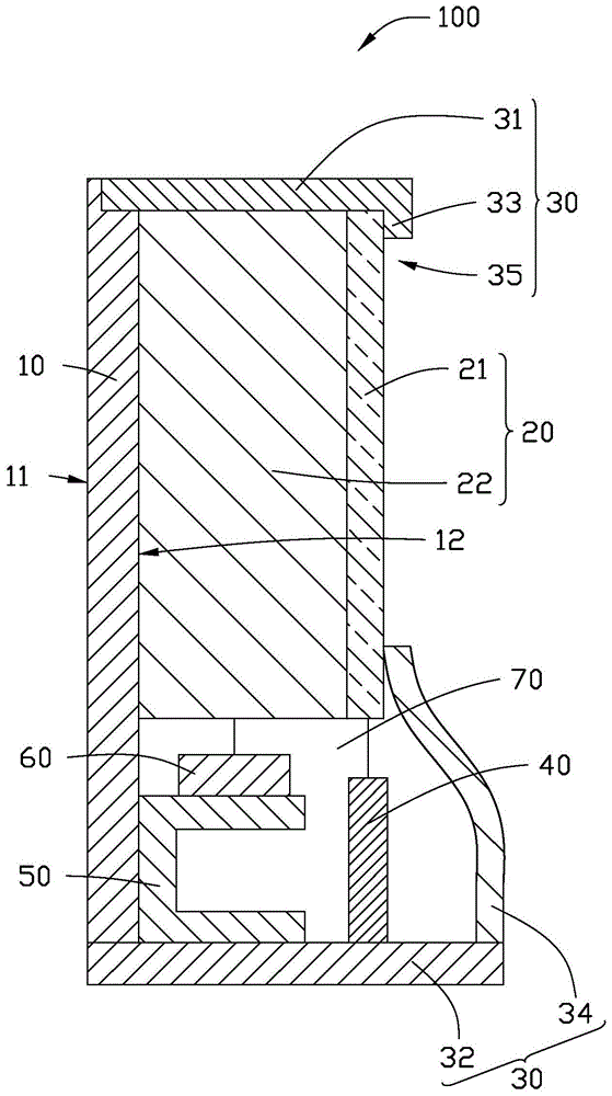
图2是图1所示的超薄电视的剖视图。FIG. 2 is a cross-sectional view of the ultra-thin TV shown in FIG. 1 .
图3是图2所示的光学模组的剖视图。FIG. 3 is a cross-sectional view of the optical module shown in FIG. 2 .
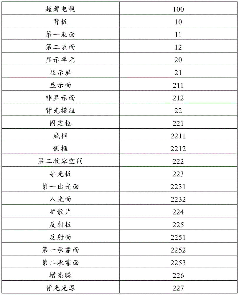
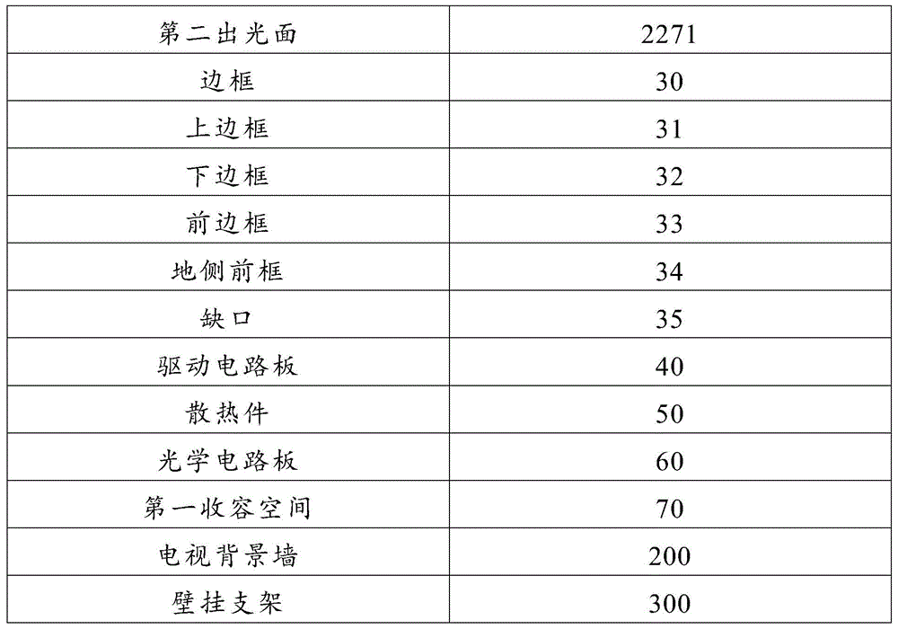
主要元件符号说明Description of main component symbols
如下具体实施方式将结合上述附图进一步说明本发明。The following specific embodiments will further illustrate the present invention in conjunction with the above drawings.
具体实施方式Detailed ways
为能进一步阐述本发明达成预定发明目的所采取的技术手段及功效,以下结合附图1-3及较佳实施方式,对本发明提供的镂空柔性电路板及其制作方法的具体实施方式、结构、特征及其功效,作出如下详细说明。In order to further illustrate the technical means and effects adopted by the present invention to achieve the predetermined purpose of the invention, the following describes the specific implementation, structure, The features and their effects are described in detail as follows.
请参阅图1-3,本发明一实施例提供一种超薄电视100,该超薄电视100包括一背板10、一与该背板10相对的显示单元20、一边框30、一驱动电路板40、一散热件50及一光学电路板60。该背板10与该边框30形成一第一收容空间70,该显示单元20、该光学电路板40、该散热件50及该驱动电路板60均收容在该第一收容空间70内。Referring to FIGS. 1-3 , an embodiment of the present invention provides an
该背板10包括一第一表面11及一与该第一表面11相背的第二表面12。其中,该第一表面11为一平面。当安装该超薄电视100时,该第一表面11与形成在电视背景墙200上的壁挂支架300的表面相贴合。The
该显示单元20包括一显示屏21及一背光模组22。该背光模组22位于该背板10与该显示屏21之间。The
该显示屏21包括一显示面211及一与该显示面211相背的非显示面212。该非显示面212面向该背光模组22。The
在本实施例中,该显示屏21为液晶显示屏,在其他实施例中,该显示屏21也可以是等离子显示屏。In this embodiment, the
在本实施例中,该背光模组22包括一固定框221、一导光板223、一扩散片224、至少一反射板225、一增亮膜226及多个背光光源227。In this embodiment, the
该固定框221大体呈“U”字型,该固定框221包括一底框2211及两个垂直于该底框2211的侧框2212。该显示屏21形成在该固定框221的两个该侧框2212的远离该底框2211的一端且与该固定框221一起形成一第二收容空间222。该导光板223、该扩散片224、该反射板225、该增亮膜226及该背光光源227均收容于该第二收容空间222内。The
该导光板223包括一第一出光面2231及一与该第一出光面2231相背的入光面2232。该第一出光面2231与该显示屏21的该非显示面212相贴合。该导光板223的两端分别固定在该固定框221的两个该侧框2212上。The
该扩散片224与该导光板223的入光面2232相抵接。该扩散片224的两端分别固定在该固定框221的两个该侧框2212上。The
该反射板225用于将射向该侧框2212上的光线反射到该扩散片224上,进而使得光线完全进入该导光板223以减少光线的损失。The reflecting
在本实施例中,该反射板225有两个。每个该反射板225包括一反射面2251、一第一承靠面2252及一第二承靠面2253。该第一承靠面2252与该第二承靠面2253垂直,该第一承靠面2252抵靠在该侧框2212上,该第二承靠面2253抵靠在该增亮膜226上。该反射面2251分别与该第一承靠面2252及该第二承靠面2253相交且分别相对于该第一承靠面2252及该第二承靠面2253倾斜一定角度。定义该反射面2251相对于该第一承靠面2252及该第二承靠面2253的倾斜角度分别为α及β,则α+β=90°。优选地,α=β=45°。In this embodiment, there are two reflecting
该增亮膜226的两端分别固定在两个该侧框2212上且与该扩散片224正对,用于改善整个背光模组的发光效率。Two ends of the
多个该背光光源227位于该底框2211上,每个该背光光源227均包括一第二出光面2271,该第二出光面2271与该增亮膜226位置相对。A plurality of the
在本实施例中,多个该背光光源227呈矩阵排列在该底框2211上。In this embodiment, a plurality of the
该背光光源227可以为发光二极管(light emitting diode,LED)或是激光二极管(diode laser,LD)等常见背光光源。The
该边框30用于保护该显示单元20、该光学电路板40、该散热件50及该驱动电路板60等超薄电视的必备元件。The
该边框30包括一垂直于该背板10一端的上边框31、一与该上边框31相背且垂直于该背板10另一端的下边框32、一垂直于该上边框31且平行于该背板10的前边框33及一与该背板10相背且大致垂直于该下边框32的地侧前框34。该前边框33与该地侧前框34之间具有一个缺口35,该显示屏21从该缺口35内裸露出来。该地侧前框34相对该前边框33向远离该背板10的方向突出。The
该驱动电路板40设置在该地侧前框34内且位于该背板10与该地侧前框34之间,该驱动电路板40与该显示屏21电连接,用于驱动该显示屏21。The
该散热件50设置在该地侧前框34内且位于该背板10与该驱动电路板40之间,用于对该超薄电视100散热。The
在本实施例中,该散热件50通过铝挤工艺制成。In this embodiment, the
该光学电路板60设置在该地侧前框34内且与该背光光源227电连接。在本实施例中,该光学电路板60设置在该散热件50上。优选地,该光学电路板60设置在该散热件50的平行于该下边框32的面上。The
另外,该超薄电视100还包括一供电电源(图未示)、一扬声器(图未示)等。该供电电源及该扬声器等均设置在该地侧前框34内。In addition, the
相对于现有技术,本发明提供的超薄电视,将背板的远离该显示屏的面设计成全平面,并在地侧设计一向远离该背板的方向突出的地侧前框,并将原来收容在系统后盖内的元件(驱动电路板、扬声器、供电电源等)收容在该地侧前框内,可以节省现有技术中的系统后盖所占用的空间,进而减少电视占用空间、达到电视整机薄化设计目的。Compared with the prior art, in the ultra-thin TV provided by the present invention, the surface of the backplane that is far from the display screen is designed to be a full plane, and the ground-side front frame that protrudes in the direction away from the backplane is designed on the ground side, and the original The components (drive circuit board, speaker, power supply, etc.) accommodated in the rear cover of the system are accommodated in the front frame on the ground side, which can save the space occupied by the rear cover of the system in the prior art, thereby reducing the space occupied by the TV and achieving The purpose of thinning the TV set.
以上所述,仅是本发明的较佳实施方式而已,并非对本发明任何形式上的限制,虽然本发明已是较佳实施方式揭露如上,并非用以限定本发明,任何熟悉本专业的技术人员,在不脱离本发明技术方案范围内,当可利用上述揭示的技术内容做出些许更动或修饰为等同变化的等效实施方式,但凡是未脱离本发明技术方案内容,依据本发明的技术实质对以上实施方式所做的任何简单修改、等同变化与修饰,均仍属于本发明技术方案的范围内。The above is only the preferred embodiment of the present invention, and does not limit the present invention in any form. Although the present invention has been disclosed as a preferred embodiment as described above, it is not intended to limit the present invention. , without departing from the scope of the technical solution of the present invention, when the technical content disclosed above can be used to make some changes or modifications to equivalent embodiments with equivalent changes, provided that the content of the technical solution of the present invention is not departed from, the technical solution of the present invention Substantially any simple modifications, equivalent changes and modifications made to the above embodiments still fall within the scope of the technical solutions of the present invention.
Claims (10)
Priority Applications (3)
| Application Number | Priority Date | Filing Date | Title |
|---|---|---|---|
| CN201610983237.5A CN108063906B (en) | 2016-11-07 | 2016-11-07 | ultra thin tv |
| TW105138079A TWI633367B (en) | 2016-11-07 | 2016-11-21 | Ultrathin television |
| US15/604,823 US10334203B2 (en) | 2016-11-07 | 2017-05-25 | Thin-profile television device |
Applications Claiming Priority (1)
| Application Number | Priority Date | Filing Date | Title |
|---|---|---|---|
| CN201610983237.5A CN108063906B (en) | 2016-11-07 | 2016-11-07 | ultra thin tv |
Publications (2)
| Publication Number | Publication Date |
|---|---|
| CN108063906A CN108063906A (en) | 2018-05-22 |
| CN108063906B true CN108063906B (en) | 2020-10-30 |
Family
ID=62064949
Family Applications (1)
| Application Number | Title | Priority Date | Filing Date |
|---|---|---|---|
| CN201610983237.5A Expired - Fee Related CN108063906B (en) | 2016-11-07 | 2016-11-07 | ultra thin tv |
Country Status (3)
| Country | Link |
|---|---|
| US (1) | US10334203B2 (en) |
| CN (1) | CN108063906B (en) |
| TW (1) | TWI633367B (en) |
Citations (6)
| Publication number | Priority date | Publication date | Assignee | Title |
|---|---|---|---|---|
| CN201491159U (en) * | 2009-07-24 | 2010-05-26 | 康佳集团股份有限公司 | Ultrathin television set |
| CN101975361A (en) * | 2010-10-19 | 2011-02-16 | 友达光电股份有限公司 | Side-lit backlight module |
| TWM453175U (en) * | 2012-11-19 | 2013-05-11 | Global Lighting Technologies Taiwan Inc | Liquid crystal television backplane module, liquid crystal television backlight module and liquid crystal television structure |
| CN103517012A (en) * | 2012-06-29 | 2014-01-15 | Tcl集团股份有限公司 | Panel split liquid crystal television with extremely thin narrow edge |
| CN204269982U (en) * | 2014-11-14 | 2015-04-15 | Tcl光电科技(惠州)有限公司 | LCD module and radiator structure thereof |
| CN204350158U (en) * | 2015-01-27 | 2015-05-20 | 冠捷显示科技(厦门)有限公司 | A kind of ultra thin type TV |
Family Cites Families (20)
| Publication number | Priority date | Publication date | Assignee | Title |
|---|---|---|---|---|
| US7649674B2 (en) * | 2002-06-10 | 2010-01-19 | E Ink Corporation | Electro-optic display with edge seal |
| US20080198098A1 (en) * | 2006-10-21 | 2008-08-21 | Metrologic Instruments, Inc. | Electronic sign |
| US20110098083A1 (en) * | 2008-05-19 | 2011-04-28 | Peter Lablans | Large, Ultra-Thin And Ultra-Light Connectable Display For A Computing Device |
| CN101753930A (en) * | 2008-12-12 | 2010-06-23 | 康佳集团股份有限公司 | Method for realizing ultra-thin television and device thereof |
| CN102625073B (en) * | 2012-03-26 | 2013-11-20 | 南京熊猫电子制造有限公司 | Ultra-thinning method of flat liquid crystal TV and flat liquid crystal TV structure |
| US9140930B2 (en) * | 2012-04-01 | 2015-09-22 | Shenzhen China Star Optoelectronics Technology Co., Ltd. | Slim frame backlight module |
| US20130301297A1 (en) * | 2012-05-09 | 2013-11-14 | Shenzhen China Star Optoelectronics Technology Co, Ltd. | Backlight Module |
| US9030642B2 (en) * | 2012-09-11 | 2015-05-12 | Shenzhen China Star Optoelectronics Technology Co., Ltd. | Liquid crystal display device |
| CN103268029B (en) * | 2013-05-24 | 2015-11-25 | 深圳市华星光电技术有限公司 | A kind of display module and display |
| US9323393B2 (en) * | 2013-06-03 | 2016-04-26 | Qualcomm Incorporated | Display with peripherally configured ultrasonic biometric sensor |
| JP6586092B2 (en) * | 2013-12-19 | 2019-10-02 | コーニング インコーポレイテッド | Relief surface for display applications |
| US9817500B2 (en) * | 2013-12-27 | 2017-11-14 | Intel Corporation | Mechanism for facilitating flexible wraparound displays for computing devices |
| CN204348262U (en) * | 2015-01-04 | 2015-05-20 | 京东方科技集团股份有限公司 | A kind of display device and frame assembly thereof |
| US9835925B1 (en) * | 2015-01-08 | 2017-12-05 | E Ink Corporation | Electro-optic displays, and processes for the production thereof |
| CN104915064B (en) * | 2015-07-02 | 2018-05-08 | 合肥鑫晟光电科技有限公司 | A kind of touch control liquid crystal display device |
| US9640108B2 (en) * | 2015-08-25 | 2017-05-02 | X-Celeprint Limited | Bit-plane pulse width modulated digital display system |
| US9818804B2 (en) * | 2015-09-18 | 2017-11-14 | Universal Display Corporation | Hybrid display |
| US10066819B2 (en) * | 2015-12-09 | 2018-09-04 | X-Celeprint Limited | Micro-light-emitting diode backlight system |
| US9928771B2 (en) * | 2015-12-24 | 2018-03-27 | X-Celeprint Limited | Distributed pulse width modulation control |
| CN105700214B (en) * | 2016-04-26 | 2019-03-01 | 深圳市华星光电技术有限公司 | Back board structure and flexible displays |
-
2016
- 2016-11-07 CN CN201610983237.5A patent/CN108063906B/en not_active Expired - Fee Related
- 2016-11-21 TW TW105138079A patent/TWI633367B/en not_active IP Right Cessation
-
2017
- 2017-05-25 US US15/604,823 patent/US10334203B2/en active Active
Patent Citations (6)
| Publication number | Priority date | Publication date | Assignee | Title |
|---|---|---|---|---|
| CN201491159U (en) * | 2009-07-24 | 2010-05-26 | 康佳集团股份有限公司 | Ultrathin television set |
| CN101975361A (en) * | 2010-10-19 | 2011-02-16 | 友达光电股份有限公司 | Side-lit backlight module |
| CN103517012A (en) * | 2012-06-29 | 2014-01-15 | Tcl集团股份有限公司 | Panel split liquid crystal television with extremely thin narrow edge |
| TWM453175U (en) * | 2012-11-19 | 2013-05-11 | Global Lighting Technologies Taiwan Inc | Liquid crystal television backplane module, liquid crystal television backlight module and liquid crystal television structure |
| CN204269982U (en) * | 2014-11-14 | 2015-04-15 | Tcl光电科技(惠州)有限公司 | LCD module and radiator structure thereof |
| CN204350158U (en) * | 2015-01-27 | 2015-05-20 | 冠捷显示科技(厦门)有限公司 | A kind of ultra thin type TV |
Also Published As
| Publication number | Publication date |
|---|---|
| TWI633367B (en) | 2018-08-21 |
| CN108063906A (en) | 2018-05-22 |
| US10334203B2 (en) | 2019-06-25 |
| US20180131896A1 (en) | 2018-05-10 |
| TW201818127A (en) | 2018-05-16 |
Similar Documents
| Publication | Publication Date | Title |
|---|---|---|
| US8421971B2 (en) | Liquid crystal display module and one-piece back plate thereof | |
| KR102034890B1 (en) | Display apparatus | |
| CN102713411B (en) | Lighting device, display device, and television receiver | |
| JP6157738B2 (en) | Backlight module and liquid crystal display module using the backlight module | |
| CN103838036B (en) | Curved surface liquid crystal indicator | |
| CN104508355B (en) | Lighting device, display device and television receiving device | |
| KR20160072240A (en) | Backlight module and liquid crystal display device using backlight module | |
| WO2015096255A1 (en) | Liquid crystal display device | |
| CN106019667A (en) | Display device | |
| WO2017071030A1 (en) | Backlight unit, backlight module, and backlight module and display device | |
| WO2015139341A1 (en) | Curved liquid crystal display device | |
| US9274362B2 (en) | Curved liquid crystal display device | |
| WO2013152521A1 (en) | Direct type backlight module | |
| WO2013166747A1 (en) | Backlight module | |
| CN104583675A (en) | Lighting apparatus, display apparatus, and television receiver | |
| JP2010177076A (en) | Tandem surface light source device, and liquid crystal display device using the same | |
| US7371002B2 (en) | Back light module and system for liquid crystal panels | |
| TWI544173B (en) | Black light module with mount and displaying apparatus therewith | |
| CN104040413B (en) | Display device and radiovisor | |
| WO2015089916A1 (en) | Backlight module | |
| WO2017138080A1 (en) | Display device | |
| US20150022756A1 (en) | Backlight module and corresponding liquid crystal display device | |
| CN101910711A (en) | Lighting devices, display devices and television receivers | |
| CN205581472U (en) | Backlight unit , display module assembly and display device | |
| CN206584141U (en) | Display device and television receiver |
Legal Events
| Date | Code | Title | Description |
|---|---|---|---|
| PB01 | Publication | ||
| PB01 | Publication | ||
| SE01 | Entry into force of request for substantive examination | ||
| SE01 | Entry into force of request for substantive examination | ||
| GR01 | Patent grant | ||
| GR01 | Patent grant | ||
| CF01 | Termination of patent right due to non-payment of annual fee | ||
| CF01 | Termination of patent right due to non-payment of annual fee |
Granted publication date: 20201030 Termination date: 20211107 |