Background
The requirement of the modern astronomical telescope for the pointing accuracy is increasing day by day. In the field of radio, the typical value of the main beam width of a large-scale radio astronomical telescope (such as a FAST telescope, a delaunay 13.7-meter caliber millimeter wave telescope, and the like) is 10-50 arc seconds, and in order to ensure the observation efficiency, the pointing accuracy of the telescope is usually required to reach the order of x 1 arc second.
The telescope pointing error usually comprises a system deviation part and a random error part, wherein the system deviation part can be corrected through a pointing model, the corrected residual error is mainly the random pointing error, and the error is mainly determined by the repeated positioning accuracy of the telescope frame. In order to evaluate the repeated positioning capability of the telescope frame, the actual rotation angle of each shafting of the telescope under a given rotation instruction condition needs to be accurately measured, and the measurement accuracy often needs to reach 1-2 angular seconds or even sub-angular seconds (x 0.1 angular seconds).
In the field of astronomy, devices and methods for high precision rotation measurements include theodolites, total stations, laser trackers, cyclotachs, and the like.
Theodolite and total station are direct angle measuring equipment, and have the defects that reading needs to be manually aligned, the reading error caused by the manual alignment usually reaches the order of arc seconds, and the requirement of high-precision rotation measurement cannot be met. Furthermore, such devices need to be mounted on a rack by tooling and rotate with the rack, which can cause inconvenience in the measurement of small racks. The theodolite requires a horizontal attitude when working normally, so that the application of the theodolite in the three-dimensional rotation measurement of the space is also limited.
Laser trackers usually have high range-finding accuracy, but angular accuracy is poor, with the limit accuracy usually being on the order of x 1 arc-second. When measuring the rotation angle using the laser tracker, a reflection target is usually placed on a rotor of a gantry to be measured, and the rotation angle of the gantry is estimated by measuring the rotation angle of the target with respect to the laser tracker. Since the laser tracker is not located at the center of rotation of the gantry, there is a possibility that angle measurement errors will be amplified during the calculation.
The angular pendulum instrument has high measurement precision, and can reach the angular resolution of 1 arc second or even higher, but has the defect that the angular pendulum instrument needs to be matched with a laser interferometer for use. In addition, the angular pendulum instrument can only measure the rotation angle in a plane, and cannot measure the rotation angle on a spatial three-dimensional shaft in any direction.
Disclosure of Invention
The invention aims to provide a high-precision rotation measuring method based on a digital photogrammetry technology aiming at the defects of the prior art.
The technical scheme of the invention is as follows: a high-precision rotation measurement method based on a digital photogrammetry technology comprises the following steps: firstly, respectively sticking reflective targets on a rotor and a stator of a rotating frame, and respectively setting the quantity of the reflective targets on the stator and the rotor as Ns and Nr, wherein Ns and Nr are positive integers; secondly, photographing the reflective targets on the rotating frame under the condition that the initial rotation does not occur, and after the photographing is finished, entering each reflective target according to the photographed picturesAnd (3) resolving the three-dimensional coordinates, and recording as:

wherein i is 1,2, …, Nr; rotating a rotor of the rotating frame to the Na group angle to be measured, shooting and calculating three-dimensional coordinates respectively to obtain the three-dimensional coordinates of each reflective target under each angle to be measured, and recording the three-dimensional coordinates as follows:
wherein i is 1,2, …, Nr, j is 1,2, …, Na and Na are positive integers,
are respectively reflective
A coordinate value of the target; fourthly, obtaining the three-dimensional coordinates of each reflective target according to the second step and the third step
And
the fitting calculates the relative rotation angle of the rotor with respect to the stator given the rotation command.
Preferably, in the fourth step, in the step of fitting calculation of the relative rotation angle of the rotor with respect to the stator under the condition of the given rotation command, the rotation angle θ at which the fitted function reaches a minimum value is found by using a least square methodjThe fitting function is:
where i is 1,2, …, Nr, j is 1,2, …, Na, | | | is modulo arithmetic, R (θ j) is a coordinate rotation matrix,
a rotation center position vector for each retroreflective target.
Preferably, the first and second electrodes are formed of a metal,rotation center position vector of reflective target in step four
The fitting comprises the following steps:
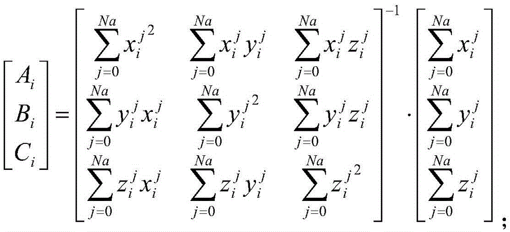
fitting the rotation plane A of each reflective targetix+Biy+Ciz=1,
Fitting the rotation axis direction vector of each reflective target
Rotating shaft of fitting rotating frame
Fitting the rotation center position vector of each reflection target
Preferably, in step four, R (θ j) is a coordinate rotation matrix defined as:
the technical scheme provided by the invention has the following beneficial effects:
1. the needed measuring equipment is simple, such as a digital camera, has no special requirement on a measuring scene, and has wide applicability;
2. the measuring equipment does not need to be erected on the rotating mechanism to be measured, so that the rotating mechanism to be measured does not need to be structurally modified;
3. the rotation angle measurement on the spatial three-dimensional shaft in any direction can be conveniently realized;
4. the shooting device can continuously shoot various rotating postures, and after the shooting is finished, the rotating angles under the rotating postures can be obtained at one time through data processing;
5. the positions of the reflective targets pasted on the rotating mechanism to be measured can be randomly distributed, but in order to obtain higher measurement accuracy, the targets need to be uniformly distributed in the rotating circumferential direction as much as possible and are far away from the rotating shaft as much as possible; the angle measurement precision can be effectively improved by increasing the number of the targets; moreover, in practical applications, the number of targets may be determined according to the final required angular accuracy.
Detailed Description
In order to make the objects, technical solutions and advantages of the present invention more apparent, the present invention is further described in detail with reference to the following embodiments. It should be understood that the specific embodiments described herein are merely illustrative of the invention and are not intended to limit the invention.
Unless the context clearly dictates otherwise, the elements and components of the present invention may be present in either single or in multiple forms and are not limited thereto. Although the steps in the present invention are arranged by using reference numbers, the order of the steps is not limited, and the relative order of the steps can be adjusted unless the order of the steps is explicitly stated or other steps are required for the execution of a certain step. It is to be understood that the term "and/or" as used herein refers to and encompasses any and all possible combinations of one or more of the associated listed items.
The high-precision rotation measurement method based on the digital photogrammetry technology provided by the embodiment of the invention can be used for rack equipment which needs to accurately adjust the angle in any rotation rack, such as a telescope rack, a tilted terahertz antenna rack and other astronomical fields.
It should be noted that the rotating frame includes a stator and a rotor, the stator is a fixed portion, the rotor is a rotatable portion, and the rotor can rotate relative to the stator, so as to adjust the angle adjustment of the rotating frame.
Specifically, the high-precision rotation measurement method based on the digital photogrammetry technology comprises the following steps:
firstly, respectively sticking reflective targets on a rotor and a stator of a rotating frame, and respectively setting the quantity of the reflective targets on the stator and the rotor as Ns and Nr, wherein Ns and Nr are positive integers.
In step one, specifically, the pasting positions of the reflective targets may be randomly distributed, but are required to be distributed in the circumferential direction of the rotation as uniformly as possible and to be as far away from the rotation axis as possible.
Secondly, shoot the reflection of light target on the rotating frame under the condition that the initial does not take place to rotate to after finishing shooting, resolving the three-dimensional coordinate according to the picture of shooting to each reflection of light target, writing:
wherein i is 1,2, …, Nr.
In the second step, specifically, the obtained three-dimensional coordinates of each reflective target are used as reference values for subsequent rotation measurement.
Rotating a rotor of the rotating frame to the Na group angle to be measured, shooting and calculating three-dimensional coordinates respectively to obtain the three-dimensional coordinates of each reflective target under each angle to be measured, and recording the three-dimensional coordinates as follows:
wherein i is 1,2, …, Nr, j is 1,2, …, Na and Na are positive integers,
respectively, are coordinate values of the reflective targets.
Fourthly, obtaining the three-dimensional coordinates of each reflective target according to the second step and the third step
And
the fitting calculates the relative rotation angle of the rotor with respect to the stator given the rotation command.
Specifically, in the step of calculating the relative rotation angle of the rotor with respect to the stator by fitting in the step four under the condition of a given rotation command, the rotation angle θ at which the fitting function reaches a minimum value is found by using the least square methodjThe fitting function is:
where i is 1,2, …, Nr, j is 1,2, …, Na, | | | is modulo arithmetic, R (θ j) is a coordinate rotation matrix,
a rotation center position vector for each retroreflective target.
Furthermore, the rotation center position vector of the reflective target in step four
IncludesThe method comprises the following steps:
fitting the rotation plane A of each reflective targetix+Biy+Ciz=1,
Fitting the rotation axis direction vector of each reflective target
Rotating shaft of fitting rotating frame
Fitting the rotation center position vector of each reflection target
Further, R (θ j) is a coordinate rotation matrix defined as:
for example, the repeated positioning precision measurement is performed on the oblique-axis terahertz antenna frame by using the high-precision rotation measurement method based on the digital photogrammetry technology provided by the embodiment of the invention.
The inclined-axis terahertz antenna frame is about 1.8 meters high, and the diameter of the bottom of the inclined-axis terahertz antenna frame is about 700 millimeters. The frame shafting comprises an azimuth axis and an oblique axis, and a crossing angle of 45 degrees is formed between the two axes. 15 and 36 reflective targets are respectively stuck on a tripod support (stator) at the bottom of the frame and a platform (rotor) at the top, and coding marks for image splicing are uniformly stuck on other outer wall parts. The postures to be measured are respectively as follows: azimuth axes 0 °, 120 ° and 240 °, and oblique axes 0 °, 90 ° and 180 °.
Firstly, the measurement process is simulated on a computer, the error of the target coordinate measurement is assumed to be random error in the simulation, and the root mean square is assumed to be 3 μm. The method provided by the patent is utilized to carry out analog simulation on the measurement process, and finally the root mean square of the angle measurement error is 0.4 arc second.
The repeat positioning accuracy of the antenna mount is then measured using a commercial digital photogrammetry system. The repeated positioning accuracy of the azimuth axis and the oblique axis was found to be 3.3 arcsec RMS and 3.9 arcsec RMS, respectively, by measurement. The coordinate measurement precision of the measurement system is about 3 mu m RMS, the angle repeated measurement precision is better than 0.5 arc second RMS, and the result is consistent with the simulation result.
It will be evident to those skilled in the art that the invention is not limited to the details of the foregoing illustrative embodiments, and that the present invention may be embodied in other specific forms without departing from the spirit or essential attributes thereof. The present embodiments are therefore to be considered in all respects as illustrative and not restrictive, the scope of the invention being indicated by the appended claims rather than by the foregoing description, and all changes which come within the meaning and range of equivalency of the claims are therefore intended to be embraced therein.
Furthermore, it should be understood that although the present description refers to embodiments, not every embodiment may contain only a single embodiment, and such description is for clarity only, and those skilled in the art should integrate the description, and the embodiments may be combined as appropriate to form other embodiments understood by those skilled in the art.