Disclosure of Invention
The invention aims to provide a test liquid medicine drip irrigation rack to realize automatic replacement of a liquid medicine bottle.
In order to achieve the purpose, the basic technical scheme of the invention is as follows: a test liquid medicine drip irrigation rack comprises a rack body, wherein rack legs and a fixed plate are arranged on the rack body, a lever is arranged on the upper portion of the rack body, one end of the lever is connected with a first transverse rack in a sliding mode and hinged to a first hanging barrel, a first bevel gear is rotatably connected to the fixed plate on the outer side of the first transverse rack and meshed with the first transverse rack, and a vertical rack meshed with the first bevel gear is fixedly connected to the first hanging barrel; the other end of the lever is provided with a spring, a second transverse rack is arranged between the spring and a fulcrum of the lever, the second transverse rack is connected to the lever in a sliding manner and is fixedly connected with the spring, a second hanging cylinder is hinged to the second transverse rack, a second bevel gear is rotatably connected to a fixing plate on the outer side of the second transverse rack and is meshed with the second transverse rack, a winding shaft is fixedly connected to the second bevel gear, a pull rope is wound on the winding shaft, one end, away from the winding shaft, of the pull rope is connected with a piston, a pipeline is arranged in the frame body, the piston is located in the pipeline and is in clearance fit with the pipeline, one end, away from the spring, of the second transverse rack penetrates through the side wall of the pipeline and extends inwards, the second transverse rack is located below the piston, the lower portion of the pipeline is a spiral bent pipe, a through groove is formed in the bent pipe, a round ball is arranged in the bent, the end of the support rod, which is positioned at the outer side of the bent pipe, is provided with a chuck.
The principle of the scheme is as follows: in practical application, the piston is a heavy piston made of iron or steel and the like, the ball is a light ball made of plastic and the like, and two liquid medicine bottles needing drip irrigation are respectively placed in the first hanging cylinder and the second hanging cylinder. When the infusion tube is started, the first hanging tube is positioned at the end part of the lever, the second hanging tube is close to the middle part of the lever, one end of the lever, which is provided with the first hanging tube, is inclined downwards, and the infusion tube penetrates through the chuck and is inserted into the liquid medicine bottle in the first hanging tube. When the liquid medicine in the liquid medicine bottle is gradually reduced in the process of carrying out drip irrigation through the liquid conveying pipe, the mass of the liquid medicine bottle becomes light, one end, provided with the first rack, of the lever is lifted up due to the fact that the weight of the end becomes light, the vertical rack on the first hanging barrel rises along with the first hanging barrel, the first bevel gear meshed with the vertical rack is pushed to rotate, and due to the fact that the first transverse rack is meshed with the first bevel gear, the first transverse rack moves transversely under the rotation of the first bevel gear. The first transverse rack is gradually close to the middle part of the lever, and contacts and pushes the second transverse rack to enable the second transverse rack to move transversely. The second rack bar moves and pushes the second bevel gear engaged therewith to rotate, thereby rotating the spool on the second bevel gear and lengthening the rope wound on the spool. Meanwhile, the second transverse rack drives the second hanging cylinder to move towards the end of the lever, and the spring is compressed. At this time, because the liquid medicine in the liquid medicine bottle in the first hanging barrel is completely infused and the weight of the liquid medicine bottle in the first hanging barrel is less than that of the liquid medicine bottle in the second hanging barrel, one end of the lever, which is provided with the second hanging barrel, sinks to be lower than the other end of the lever.
The second transverse rack moves to slide out of the pipeline, the pipeline is opened, the pull rope is lengthened, the piston slides downwards gradually along the pipeline under the action of gravity until the pull rope is stretched straight, so that air in the pipeline is extruded, and the air flow pushes the ball in the elbow to slide downwards. Because the bent pipe is spiral, the ball drives the supporting rod and the clamping head to rotate and sink along the bent pipe. When the chuck sinks, the infusion tube is pulled downwards, the infusion tube is pulled out from the liquid medicine bottle on the first hanging tube, then the infusion tube moves to the lower part of the second hanging tube along with the chuck, meanwhile, the second hanging tube carries the liquid medicine bottle to sink, the liquid medicine bottle automatically contacts with the needle head of the infusion tube, and under the action of the inertial impact force of the liquid medicine bottle, the needle head is automatically inserted into the liquid medicine bottle, so that the automatic bottle replacement of the infusion support is realized.
When the ball sinks along the rotation of return bend, the air current in the ball collision return bend makes the air current impact make return bend vibration sound production on the lateral wall of return bend to the suggestion is automatic to change the bottle, so that the experimenter drips irrigation the control of progress to the liquid medicine, makes it can carry out in good time appropriate regulation to the experiment progress according to driping irrigation the progress.
When the weight of the liquid medicine bottle in the second hanging cylinder is gradually reduced, one end of the lever, which is provided with the second hanging cylinder, is gradually lifted. Because the liquid medicine bottle quality becomes light to in the in-process that the second horizontal rack rises, the pressure of second horizontal rack that the spring received reduces gradually, when second horizontal rack rises to certain degree, the elasticity of spring will promote the second horizontal rack and move the return to the middle part of lever. The second transverse rack moves reversely to enable the second bevel gear to rotate reversely, the winding shaft rotates reversely along with the second bevel gear to shorten the pull rope, and therefore the piston is lifted upwards, the piston moves upwards to enable the round ball in the bent pipe to be pushed by air flow to move upwards to return. The ball moves to tear the infusion tube out of the liquid medicine bottle, so that the liquid medicine bottle automatically stops infusion, and the liquid medicine bottle and the clamping head rotate together to lift and return. The ball collides the lateral wall of return bend once more of in-process, sends the collision sound to the suggestion is driped irrigation and is accomplished, in order to remind the experimenter in time to carry out follow-up experiment or observation. The first alarm prompt is mainly to extrude gas into the bent pipe through the pipeline, so that the air pressure in the bent pipe is increased, and the gas in the bent pipe vibrates and collides the bent pipe through the vibration of the round ball to realize sound production, so that the sound is more stuffy in an environment with higher air pressure; and in the warning suggestion of second time, the piston moved up, the air current is by the updraft, and the air current pressure in the return bend is less, is difficult to the vibration sound production, consequently only realizes the sound production through the ball to the collision of return bend, and sound is comparatively loud, and the stereo set that twice sent is different to some extent, and easily the difference makes the experimenter correctly distinguish, avoids the experimenter to produce and obscures.
The beneficial effect of this scheme: according to the invention, the piston is moved downwards through the change of the weight of the liquid medicine bottle, the liquid conveying pipe is automatically inserted into another liquid medicine bottle, the automatic replacement of the liquid medicine bottle can be realized, the ball is pushed to collide in the bent pipe through air flow, two alarm prompts are respectively realized, when the first alarm prompt is given, the air flow in the bent pipe vibrates to collide with the bent pipe through the vibration of the ball so as to prompt the automatic bottle replacement, when the second alarm prompt is given, the collision sounding of the bent pipe is only given an end prompt through the ball, and an experimenter can clearly distinguish.
Preferably, as an improvement, the end of the lever provided with the first transverse rack is also provided with a lifting rope, and the lifting rope is connected with a pull ring. By pulling the pull ring, the lever can be inclined through the lifting rope, so that the hanging cylinder is lowered, and the liquid medicine bottle can be conveniently placed into the hanging cylinder.
Preferably, as an improvement, the outer pipe wall of the elbow pipe is provided with a plurality of bells. When the bent pipe vibrates, the bell sounds due to the vibration, the sound production effect is enhanced, and the experimenter is effectively reminded.
Preferably, as an improvement, the frame foot is in a hemispherical shape, and the frame foot is provided with universal wheels. The hemispherical cover body can uniformly disperse the weight of the rack body to the circumferential direction, so that the balance and stability of the rack body are well maintained. Through the universal wheel that slides, make the support body can be moved everywhere to the experimental group of the different positions of being convenient for uses.
Preferably, as a modification, the clip is U-shaped. Therefore, the infusion tube can directly penetrate into the chuck from the U-shaped opening on the chuck and is convenient to take out from the opening.
Preferably, as a modification, the lever and the fixed plate are covered with a housing on the outer side. The shell can be sheltered from in the outside formation of lever and fixed plate, prevents that the dust from piling up on lever and fixed plate, the health clearance of the infusion support of being convenient for.
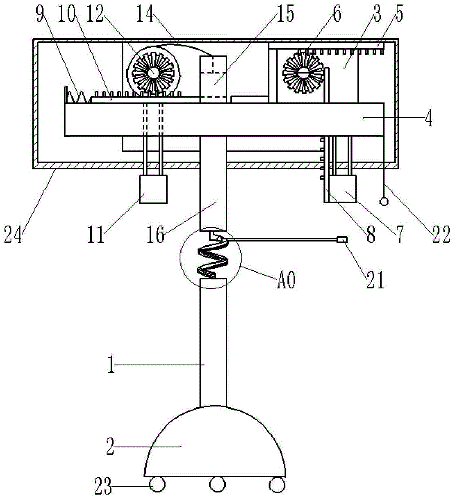
The embodiment is basically as shown in figure 1: a test liquid medicine drip irrigation rack comprises a rack body 1, wherein a hemispherical rack foot 2 is arranged at the bottom of the rack body 1, and a universal wheel 23 is arranged on the rack foot 2. The top of the frame body 1 is provided with a fixed plate 3 and a lever 4, and the outer sides of the lever 4 and the fixed plate 3 are covered with a shell 24. The right end of the lever 4 is hinged with a first hanging barrel 7, the right part of the lever 4 is connected with a sliding strip in a sliding mode, a first transverse rack 5 is welded on the sliding strip, a first bevel gear 6 is rotatably connected onto the fixing plate 3 on the lower side of the first transverse rack 5 through a bearing, the first bevel gear 6 is meshed with the first transverse rack 5, and a vertical rack 8 meshed with the first bevel gear 6 is welded on the first hanging barrel 7. The right end of the lever 4 is also provided with a lifting rope 22, and a pull ring is bonded on the lifting rope 22. A spring 9 is arranged at the left end of the lever 4, a second transverse rack 10 is arranged between the spring 9 and the fulcrum of the lever 4, the second transverse rack 10 is connected to the lever 4 in a sliding mode and welded with the right end of the spring 9, a second hanging barrel 11 is hinged to the second transverse rack 10, a second bevel gear 12 is rotatably connected to the fixing plate 3 on the outer side of the second transverse rack 10 through a bearing, the second bevel gear 12 is meshed with the second transverse rack 10, as shown in fig. 2, a winding shaft 13 is welded to the second bevel gear 12, a pull rope 14 is wound on the winding shaft 13, and a piston 15 is bonded to the lower end of the pull rope 14. The frame body 1 is internally provided with a pipeline 16, the piston 15 is positioned in the pipeline 16 and is in clearance fit with the pipeline 16, the right end of the second transverse rack 10 penetrates through the side wall of the pipeline 16 and extends into the pipeline 16, the second transverse rack 10 is positioned below the piston 15, the lower part of the pipeline 16 is a spiral bent pipe 17, as shown in fig. 3, the outer wall of the bent pipe 17 is provided with a plurality of bells 25, the pipe wall of the bent pipe 17 is provided with a through groove 18, the bent pipe 17 is internally provided with a round ball 19, the round ball 19 is welded with a support rod 20, the support rod 20 penetrates through the through groove 18 and extends to the outer side of the bent pipe 17, and one end of the support rod 20 positioned at the outer side.
In this embodiment, in practical application, the piston 15 is an iron solid piston, the ball 19 is a hollow ball made of plastic, the lifting rope 22 at the right end of the lever 4 is pulled to enable the right end of the lever 4 to be inclined, and the two liquid bottles are respectively placed in the first hanging cylinder 7 and the second hanging cylinder 11. Initially, the first hanging cylinder 7 is located at the right end of the lever 4, and the second hanging cylinder 11 is located near the middle of the lever 4, and the lever 4 is inclined downward and rightward by gravity. The infusion tube passes through the opening part of the U-shaped chuck 21 and is inserted into the liquid medicine bottle at the right side, the chuck 21 keeps the infusion tube straight, the liquid flows conveniently, and then the liquid drip irrigation is started.
When the liquid medicine in the right liquid medicine bottle is gradually reduced in the drip irrigation process, the quality of the liquid medicine bottle becomes light, the right end of the lever 4 is gradually lifted, the vertical rack 8 is lifted along with the lifting and pushes the first bevel gear 6 to rotate, and the first transverse rack 5 is driven by the first bevel gear 6 to move leftwards. The left end of the first rack bar 5 contacts and pushes the second rack bar 10 to move left, so that the second bevel gear 12 rotates, thereby rotating the spool 13, and the rope 14 wound around the spool 13 is lengthened. Meanwhile, the second transverse rack 10 drives the second hanging barrel 11 to move towards the left end of the lever 4, and the spring 9 is compressed. At this time, the left end of the lever 4 is inclined downward to the left.
The second transverse rack 10 moves to the left to move the right end out of the pipeline 16, the pipeline 16 is opened, meanwhile, the pull rope 14 is lengthened in the process that the winding shaft 13 rotates along with the second bevel gear 12, the piston 15 is released by the pull rope 14 to slide downwards along the pipeline 16 until the pull rope 14 is straightened, and the piston 15 pushes the air flow to move and pushes the round ball 19 in the elbow 17 to slide downwards through the air flow. The ball 19 rotates and sinks the rod 20 along the elbow 17 together with the chuck 21. When the chuck 21 sinks, the infusion tube is pulled downwards to be pulled out from the liquid medicine bottle at the right side, then the infusion tube moves to the lower side of the second hanging barrel 11 together with the round ball 19, and when the second hanging barrel 11 carries the liquid medicine bottle at the left side to sink, the needle is inserted into the liquid medicine bottle, so that the automatic bottle replacement of the drip irrigation rack is realized. When the round ball 19 rotates and sinks along the bent pipe 17, the round ball collides with the side wall of the bent pipe 17, so that the air flow in the bent pipe 17 vibrates to collide with the bent pipe to sound, the automatic bottle changing is prompted, the bell 25 vibrates along with the vibration, and the sound production effect is enhanced.
The weight of the left liquid medicine bottle is gradually reduced in the drip irrigation process, and the left end of the lever 4 is gradually lifted. The spring 9 pushes the second transverse rack 10 to move and return to the middle of the lever 4. The second transverse rack 10 makes the second bevel gear 12 rotate reversely, the winding shaft 13 rotates reversely along with the second bevel gear 12 to wind and shorten the pull rope 14, the pull rope 14 lifts the piston 15, the ball 19 is pushed by the air flow to move upwards and return to the position, the infusion tube is pulled out from the liquid medicine bottle at the left, the liquid medicine bottle stops drip irrigation automatically, and then the support rod 20 on the ball 19 rotates together with the infusion tube to lift and return to the position. When moving upwards, the ball 19 collides with the bent pipe 17 again to make the bent pipe 17 sound, thereby prompting the completion of the transfusion and reminding the experimenter to perform subsequent experiments and experimental observation in time.
The foregoing is merely an example of the present invention and common general knowledge in the art of specific structures and/or features of the invention has not been set forth herein in any way. It should be noted that, for those skilled in the art, without departing from the structure of the present invention, several changes and modifications can be made, which should also be regarded as the protection scope of the present invention, and these will not affect the effect of the implementation of the present invention and the practicability of the patent. The scope of the claims of the present application shall be determined by the contents of the claims, and the description of the embodiments and the like in the specification shall be used to explain the contents of the claims.