CN107908826B - A Voltage Phase Detection Algorithm Based on Strong Tracking Kalman Filter - Google Patents
A Voltage Phase Detection Algorithm Based on Strong Tracking Kalman Filter Download PDFInfo
- Publication number
- CN107908826B CN107908826B CN201711006138.2A CN201711006138A CN107908826B CN 107908826 B CN107908826 B CN 107908826B CN 201711006138 A CN201711006138 A CN 201711006138A CN 107908826 B CN107908826 B CN 107908826B
- Authority
- CN
- China
- Prior art keywords
- phase
- voltage
- coordinate system
- value
- kalman filter
- Prior art date
- Legal status (The legal status is an assumption and is not a legal conclusion. Google has not performed a legal analysis and makes no representation as to the accuracy of the status listed.)
- Active
Links
Images


Classifications
-
- G—PHYSICS
- G06—COMPUTING OR CALCULATING; COUNTING
- G06F—ELECTRIC DIGITAL DATA PROCESSING
- G06F30/00—Computer-aided design [CAD]
- G06F30/20—Design optimisation, verification or simulation
Landscapes
- Engineering & Computer Science (AREA)
- Physics & Mathematics (AREA)
- Theoretical Computer Science (AREA)
- Computer Hardware Design (AREA)
- Evolutionary Computation (AREA)
- Geometry (AREA)
- General Engineering & Computer Science (AREA)
- General Physics & Mathematics (AREA)
- Stabilization Of Oscillater, Synchronisation, Frequency Synthesizers (AREA)
- Measuring Phase Differences (AREA)
Abstract
本发明公开了一种基于强跟踪卡尔曼滤波器的电压相位检测算法,具体为:步骤1,将检测到的三相电压Ua、Ub、Uc变换到角速度ω=100πrad/s的两相旋转xy坐标系上得到Ux和Uy;步骤2,将Ux和Uy应用低通滤波器提取出正序基波电压分量Ux +和Uy +;步骤3,将Ux +和Uy +变换到两相静止αβ坐标系上得到Uα +和Uβ +;步骤4,将步骤1中的Ux作为输入信号,设计STKF检测输入信号的突变,得到反映信号突变的增益因子K;步骤5,将增益因子K引入相位计算过程。将步骤3中的Uα +和Uβ +应用改进同步坐标系锁相环得到电压相位。本发明方法解决了传统PLL在检测精度与响应速度无法同时满足需求的问题。

The invention discloses a voltage phase detection algorithm based on strong tracking Kalman filter, which is specifically as follows: Step 1, transform the detected three-phase voltages U a , U b , U c into two phases with an angular velocity ω=100πrad/s U x and U y are obtained on the phase rotation xy coordinate system; step 2, apply a low-pass filter to U x and U y to extract the positive sequence fundamental voltage components U x + and U y + ; step 3, convert U x + and U y + are transformed into the two-phase stationary αβ coordinate system to obtain U α + and U β + ; step 4, using U x in step 1 as the input signal, design STKF to detect the sudden change of the input signal, and obtain the gain reflecting the sudden change of the signal factor K; step 5, the gain factor K is introduced into the phase calculation process. Apply U α + and U β + in step 3 to the phase-locked loop of the improved synchronous coordinate system to obtain the voltage phase. The method of the invention solves the problem that the detection accuracy and the response speed of the traditional PLL cannot meet the requirements at the same time.
Description
技术领域technical field
本发明属于电力电子技术领域,具体涉及一种基于强跟踪卡尔曼滤波器的电压相位检测算法。The invention belongs to the technical field of power electronics, in particular to a voltage phase detection algorithm based on a strong tracking Kalman filter.
背景技术Background technique
从18世纪工业革命之后,石油、天然气、煤炭等化石能源的大量使用给人类社会带来了许多问题,比如面临能源危机、全球气候变暖等恶劣状况。因此寻求清洁的可再生能源已经成为目前较为重要的一个途径。当前实际应用的可再生清洁能源中太阳能由于具有资源丰富、清洁、光伏模块便于扩容、廉价等优点得到了广泛的发展应用。Since the industrial revolution in the 18th century, the extensive use of fossil energy such as oil, natural gas, and coal has brought many problems to human society, such as facing energy crisis, global warming and other bad conditions. Therefore, seeking clean renewable energy has become a more important way at present. Among the current practical renewable clean energy sources, solar energy has been widely developed and applied due to its abundant resources, cleanliness, easy expansion of photovoltaic modules, and low cost.
太阳能通过并网逆变器接入电网,为了实现光伏的稳定并网同时向电网注入单位功率因数的电能,需要通过检测电网电压的相位使并网逆变器与电网保持同步,这就需要使用锁相环(phase-locked-loop,PLL)。目前并网变流器通常采用同步坐标系锁相环(synchronous reference frame phase-locked-loop,SRF-PLL)。当电网电压发生畸变时,通过减少SRF-PLL的带宽可以抑制其影响,但锁相环的动态响应时间将变长。当电网电压发生不平衡故障时,电压的负序分量会使SRF-PLL存在检测误差,从而影响并网变流器的正常工作。Solar energy is connected to the grid through the grid-connected inverter. In order to achieve stable grid-connection of photovoltaics and inject unit power factor power into the grid, the grid-connected inverter needs to be synchronized with the grid by detecting the phase of the grid voltage. Phase-locked-loop (phase-locked-loop, PLL). At present, grid-connected converters usually adopt a synchronous reference frame phase-locked-loop (SRF-PLL). When the grid voltage is distorted, its influence can be suppressed by reducing the bandwidth of the SRF-PLL, but the dynamic response time of the phase-locked loop will be longer. When the grid voltage is unbalanced, the negative sequence component of the voltage will cause the SRF-PLL to have a detection error, which will affect the normal operation of the grid-connected converter.
发明内容SUMMARY OF THE INVENTION
本发明的目的在于提供了一种基于强跟踪卡尔曼滤波器的电压相位检测算法,该方法解决了传统PLL在检测精度与响应速度无法同时满足需求的问题,且适用的条件更加宽泛。The purpose of the present invention is to provide a voltage phase detection algorithm based on strong tracking Kalman filter, which solves the problem that the detection accuracy and response speed of the traditional PLL cannot meet the requirements at the same time, and the applicable conditions are wider.
本发明所采用的技术方案是,一种基于强跟踪卡尔曼滤波器的电压相位检测算法,具体按照以下步骤实施:The technical solution adopted in the present invention is a voltage phase detection algorithm based on strong tracking Kalman filter, which is specifically implemented according to the following steps:
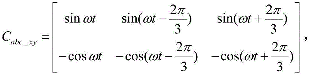
步骤1,将检测到的三相电压Ua、Ub、Uc变换到角速度ω=100πrad/s的两相旋转xy坐标系上,得到变换结果Ux和Uy;

式中:
步骤2,将由步骤1得到的Ux和Uy应用低通滤波器提取出正序基波电压分量Ux +和Uy +;Step 2, applying a low-pass filter to U x and U y obtained in
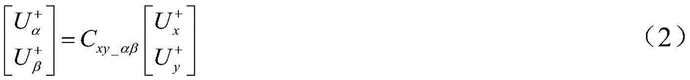
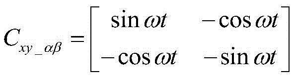
步骤3,将由步骤2得到的Ux +和Uy +变换到两相静止αβ坐标系上,得到变换结果Uα +和Uβ +;Step 3: Transform U x + and U y + obtained in step 2 into a two-phase stationary αβ coordinate system to obtain transformation results U α + and U β + ;

式中: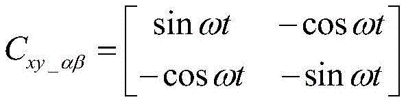
步骤4,将步骤1中的Ux作为输入信号,设计STKF检测输入信号的突变,得到反映信号突变的增益因子K;Step 4, using U x in
步骤5,对传统同步坐标系锁相环进行改进,将由步骤4得到的增益因子K引入相位计算过程,将步骤3中的Uα +和Uβ +应用到改进同步坐标系锁相环中得到电压相位。Step 5, improve the traditional synchronous coordinate system phase-locked loop, introduce the gain factor K obtained in step 4 into the phase calculation process, and apply U α + and U β + in step 3 to the improved synchronous coordinate system phase-locked loop to obtain voltage phase.
本发明的特点还在于,The present invention is also characterized in that,
步骤4中STKF的具体设计方法按照以下步骤实施:The specific design method of STKF in step 4 is implemented according to the following steps:
步骤4.1,令STKF的输入信号为z(k),待提取的信号为x(k),剩余的噪声信号为w(k),这些变量满足如下关系:Step 4.1, let the input signal of STKF be z(k), the signal to be extracted is x(k), and the remaining noise signal is w(k). These variables satisfy the following relationship:

步骤4.2,由x在k-1时刻的值x(k-1)预测k时刻的预测值为x(k|k-1);P(k)为x(k)与预测值x(k|k-1)的预测协方差,其在k时刻的预测值P(k|k-1)由k-1时刻的值P(k-1)预测得到;x和P的预测值计算公式:Step 4.2, from the value x(k-1) of x at time k-1, predict the predicted value at time k of x(k|k-1); P(k) is x(k) and the predicted value x(k| The prediction covariance of k-1), the predicted value P(k|k-1) at time k is predicted by the value P(k-1) at time k-1; the calculation formula of the predicted value of x and P:

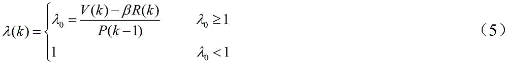
式中λ(k)为渐消因子,用于提高对输入信号突变的响应,λ(k)的计算公式为:In the formula, λ(k) is the fading factor, which is used to improve the response to the sudden change of the input signal. The calculation formula of λ(k) is:

式中,R(k)为信号中叠加的噪声信号w(k)的方差;β为平滑状态估计值的弱化引子,β取1;另外x(0)=0,P(0)=1;In the formula, R(k) is the variance of the noise signal w(k) superimposed in the signal; β is the weakening primer of the smooth state estimation value, and β is 1; in addition, x(0)=0, P(0)=1;
步骤4.3,应用k时刻P的预测值计算增益因子K:Step 4.3, calculate the gain factor K using the predicted value of P at time k:
K=P(k|k-1)(P(k|k-1)+R(k)) (6)。K=P(k|k-1)(P(k|k-1)+R(k)) (6).
步骤5中的改进同步坐标系锁相环具体按照以下步骤实施:The improved synchronous coordinate system phase-locked loop in step 5 is specifically implemented according to the following steps:
步骤5.1,将步骤3中的Uα +和Uβ +应用Park变换,得到Ud +和Uq +,Step 5.1, apply Park transform to U α + and U β + in step 3 to obtain U d + and U q + ,

式中:θ为锁相环输出的电压相位;In the formula: θ is the voltage phase output by the phase-locked loop;
步骤5.2,将Uq +与增益因子K相乘做为PI调节器的输入;Step 5.2, multiply U q + by the gain factor K as the input of the PI regulator;
步骤5.3,将PI调节器的输出进行积分得到相位值θ,将该θ值反馈进入Park变换,当PI调节稳定,Uq +为0时,θ值为所测正序基波电压的相位。Step 5.3: Integrate the output of the PI regulator to obtain the phase value θ, and feed the θ value into the Park transform. When the PI adjustment is stable and U q + is 0, the θ value is the phase of the measured positive-sequence fundamental voltage.
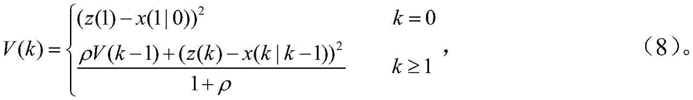
步骤4.2的式(5)中In formula (5) of step 4.2
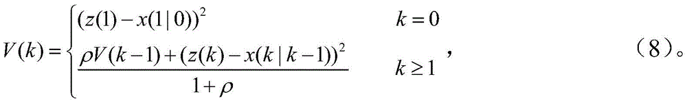
式(8)中ρ为遗忘因子,取0.95。In formula (8), ρ is the forgetting factor, which is 0.95.
本发明的有益效果是通过应用定转速旋转坐标系和低通滤波器可以从畸变且不平衡的电压中提取出正序基波电压,从而为锁相提供了基本保证。但是该过程在电压发生相位突变时,动态响应较慢。本发明进一步设计可以检测电压突变的STKF,其输出为增益因子K。将K引入相位计算过程,从而显著提高了电压相位突变时锁相的动态性。因此本发明给出的锁相环可以在电压畸变且不平衡的条件下快速进行锁相。The beneficial effect of the present invention is that the positive-sequence fundamental voltage can be extracted from the distorted and unbalanced voltage by applying a fixed-speed rotating coordinate system and a low-pass filter, thereby providing a basic guarantee for phase locking. However, the dynamic response of this process is slow when the voltage phase is abruptly changed. The present invention further designs an STKF capable of detecting voltage mutation, and its output is the gain factor K. K is introduced into the phase calculation process, which significantly improves the dynamics of phase locking when the voltage phase is abruptly changed. Therefore, the phase-locked loop provided by the present invention can quickly perform phase-locking under the condition of voltage distortion and unbalance.
附图说明Description of drawings
图1是本发明一种基于强跟踪卡尔曼滤波器的电压相位检测算法的原理框图;Fig. 1 is a kind of principle block diagram of the voltage phase detection algorithm based on strong tracking Kalman filter of the present invention;
图2是待测三相电压波形;Figure 2 is the three-phase voltage waveform to be measured;
图3是应用本发明一种基于强跟踪卡尔曼滤波器的电压相位检测算法检测A相正序基波电压相位的波形图;Fig. 3 is the waveform diagram of applying a kind of voltage phase detection algorithm based on strong tracking Kalman filter of the present invention to detect A-phase positive sequence fundamental wave voltage phase;
图4是传统同步坐标系锁相环检测A相正序基波电压相位的波形图;Fig. 4 is the waveform diagram that the traditional synchronous coordinate system phase-locked loop detects the phase of A-phase positive-sequence fundamental wave voltage;
图5是应用本发明一种基于强跟踪卡尔曼滤波器的电压相位检测算法与应用传统同步坐标系锁相环检测U+ q的波形对比图。5 is a waveform comparison diagram of applying a voltage phase detection algorithm based on strong tracking Kalman filter of the present invention and applying a traditional synchronous coordinate system phase-locked loop to detect U + q .
具体实施方式Detailed ways
下面结合附图和具体实施方式对本发明进行详细说明。The present invention will be described in detail below with reference to the accompanying drawings and specific embodiments.
本发明为一种基于强跟踪卡尔曼滤波器的电压相位检测算法,工作原理如图1所示,具体按照以下步骤实施:The present invention is a voltage phase detection algorithm based on strong tracking Kalman filter. The working principle is shown in Figure 1, and is specifically implemented according to the following steps:
步骤1,将检测到的三相电压Ua、Ub、Uc变换到角速度ω=100πrad/s的两相旋转xy坐标系上,得到变换结果Ux和Uy;

式中: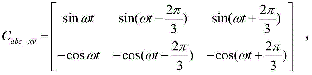
步骤2,将由步骤1得到的Ux和Uy应用低通滤波器提取出正序基波电压分量Ux +和Uy +;Step 2, applying a low-pass filter to U x and U y obtained in
步骤3,将由步骤2得到的Ux +和Uy +变换到两相静止αβ坐标系上,得到变换结果Uα +和Uβ +;Step 3: Transform U x + and U y + obtained in step 2 into a two-phase stationary αβ coordinate system to obtain transformation results U α + and U β + ;
式中:
步骤4,将步骤1中的Ux作为输入信号,设计强跟踪卡尔曼滤波器(StrongTracking Kalman Filter,STKF)检测输入信号的突变,得到反映信号突变的增益因子K;Step 4, using U x in
步骤5,对传统同步坐标系锁相环SFR-PLL进行改进,将增益因子K引入相位计算过程。将步骤3中的Uα +和Uβ +应用到改进同步坐标系锁相环中得到电压相位。Step 5, the traditional synchronous coordinate system phase-locked loop SFR-PLL is improved, and the gain factor K is introduced into the phase calculation process. Apply U α + and U β + in step 3 to the phase-locked loop of the improved synchronous coordinate system to obtain the voltage phase.
本发明的特点还在于,The present invention is also characterized in that,
步骤4中用于检测电压突变的STKF的设计方法按照以下步骤实施:The design method of STKF for detecting voltage mutation in step 4 is implemented according to the following steps:
步骤4.1,令STKF的输入信号为z(k),待提取的信号为x(k),剩余的噪声信号为w(k),这些变量满足如下关系:Step 4.1, let the input signal of STKF be z(k), the signal to be extracted is x(k), and the remaining noise signal is w(k). These variables satisfy the following relationship:

步骤4.2,由x在k-1时刻的值x(k-1)预测k时刻的预测值为x(k|k-1);P(k)为x(k)与预测值x(k|k-1)的预测协方差,其在k时刻的预测值P(k|k-1)由k-1时刻的值P(k-1)预测得到;x和P的预测值计算公式:Step 4.2, from the value x(k-1) of x at time k-1, predict the predicted value at time k of x(k|k-1); P(k) is x(k) and the predicted value x(k| The prediction covariance of k-1), the predicted value P(k|k-1) at time k is predicted by the value P(k-1) at time k-1; the calculation formula of the predicted value of x and P:

式中λ(k)为渐消因子,用于提高对输入信号突变的响应。当电压发生突变时,λ(k)将急剧增大,其值远大于1。通过判断λ(k)的值的大小即可知道电压是否发生突变。当λ(k)>1时,会引起增益因子K的改变,并保持一个工频周期,λ(k)的计算公式为:where λ(k) is the fading factor, which is used to improve the response to the sudden change of the input signal. When the voltage changes abruptly, λ(k) will increase sharply, and its value is much larger than 1. By judging the value of λ(k), we can know whether the voltage has a sudden change. When λ(k)>1, it will cause the gain factor K to change and maintain a power frequency cycle. The calculation formula of λ(k) is:
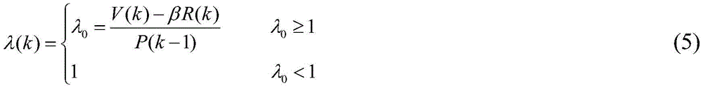
式中,R(k)为信号中叠加的噪声信号w(k)的方差;In the formula, R(k) is the variance of the noise signal w(k) superimposed in the signal;
β为平滑状态估计值的弱化引子,取值范围≥1,本发明取1;β is the weakening primer of the estimated value of the smooth state, and the value range is greater than or equal to 1, which is 1 in the present invention;

式(8)中ρ为遗忘因子,一般取0.95;In formula (8), ρ is the forgetting factor, which is generally taken as 0.95;
另外x(0)=0,P(0)=1;In addition x(0)=0, P(0)=1;
步骤4.3,应用k时刻P的预测值计算增益因子K:Step 4.3, calculate the gain factor K using the predicted value of P at time k:
K=P(k|k-1)(P(k|k-1)+R(k)) (6)K=P(k|k-1)(P(k|k-1)+R(k)) (6)
步骤5中改进同步坐标系按照以下步骤实施:The improved synchronization coordinate system in step 5 is implemented as follows:
步骤5.1,将步骤3中的Uα +和Uβ +应用Park变换,得到Ud +和Uq +;Step 5.1, apply Park transform to U α + and U β + in step 3 to obtain U d + and U q + ;

式中:θ为锁相环输出的电压相位。Where: θ is the voltage phase of the phase-locked loop output.
步骤5.2,将Uq +与增益因子K相乘做为PI调节器的输入;Step 5.2, multiply U q + by the gain factor K as the input of the PI regulator;
步骤5.3,将PI调节器的输出进行积分得到相位值θ,将该θ值反馈进入Park变换,当PI调节稳定,Uq +为0时,θ值为所测正序基波电压的相位。Step 5.3: Integrate the output of the PI regulator to obtain the phase value θ, and feed the θ value into the Park transform. When the PI adjustment is stable and U q + is 0, the θ value is the phase of the measured positive-sequence fundamental voltage.
为了验证基于强跟踪卡尔曼滤波器的电压相位检测算法的有效性,在Matlab/Simulink中进行仿真。电压基波频率为314rad/s(50Hz),有效值为60V。其中负序5次谐波电压的标幺值为0.3,正序7次谐波电压的标幺值为0.2,零序1次电压的标幺值为0.2,以下仿真波形均在此参数之下进行的。图2为三相电压波形,在1s时电压相位发生180度突变。图3为应用本发明一种基于强跟踪卡尔曼滤波器的电压相位检测算法检测A相正序基波电压相位的波形(为了减小相位检测结果的电压之间的数值差距,将电压幅值缩小6倍),结果显示本发明给出的锁相环可以在电压畸变且不平衡条件下准确地检测电压相位,当电压相位发生突变时,响应时间在一个周期以内;图4为应用传统同步坐标系锁相环检测A相正序基波电压相位的波形(为了减小相位检测结果的电压之间的数值差距,将电压幅值缩小6倍),结果显示传统同步坐标系锁相环在电网畸变且不平衡条件下不能准确地跟踪A相基波电压相位。当电压相位发生突变时,响应时间超过一个周期;图5应用本发明一种基于强跟踪卡尔曼滤波器的电压相位检测算法与传统同步坐标系锁相环中Uq +的对比波形,可以看出本发明所提的基于强跟踪卡尔曼滤波器的电压相位检测算法可以有效抑制电网电压所含谐波对检测结果的影响,且动态响应特性较好。In order to verify the validity of the voltage phase detection algorithm based on strong tracking Kalman filter, simulation is carried out in Matlab/Simulink. The voltage fundamental frequency is 314rad/s (50Hz), and the effective value is 60V. The per-unit value of the negative-sequence fifth-order harmonic voltage is 0.3, the per-unit value of the positive-sequence seventh-order harmonic voltage is 0.2, and the per-unit value of the zero-sequence first-order voltage is 0.2. The following simulation waveforms are all below this parameter. ongoing. Figure 2 shows the three-phase voltage waveform, and the voltage phase has a 180-degree sudden change at 1s. Fig. 3 is the waveform of applying a kind of voltage phase detection algorithm based on strong tracking Kalman filter of the present invention to detect A-phase positive-sequence fundamental voltage phase (in order to reduce the numerical difference between the voltages of the phase detection results, the voltage amplitude 6 times smaller), the results show that the phase-locked loop provided by the present invention can accurately detect the voltage phase under voltage distortion and unbalanced conditions, and when the voltage phase changes abruptly, the response time is within one cycle; Figure 4 shows the application of traditional synchronization The coordinate system phase-locked loop detects the waveform of the phase A positive-sequence fundamental voltage phase (in order to reduce the numerical gap between the voltages of the phase detection results, the voltage amplitude is reduced by 6 times), the results show that the traditional synchronous coordinate system phase-locked loop is in the The A-phase fundamental voltage phase cannot be accurately tracked under grid distortion and unbalanced conditions. When the voltage phase has a sudden change, the response time exceeds one cycle; Fig. 5 applies a voltage phase detection algorithm based on the strong tracking Kalman filter of the present invention and the contrast waveform of U q + in the traditional synchronous coordinate system phase-locked loop, it can be seen that It is concluded that the voltage phase detection algorithm based on the strong tracking Kalman filter proposed in the present invention can effectively suppress the influence of the harmonics contained in the grid voltage on the detection result, and has better dynamic response characteristics.
本发明的优点是,通过应用定转速旋转坐标系和低通滤波器可以从畸变且不平衡的电压中提取出正序基波电压,从而为锁相提供了基本保证。但是该过程在电压发生相位突变时,动态响应较慢。本发明进一步设计可以检测电压突变的STKF,其输出为增益因子K。将K引入相位计算过程,从而显著提高了电压相位突变时锁相的动态性。因此本发明给出的电压相位检测算法可以在电压畸变且不平衡的条件下快速进行锁相。The advantage of the present invention is that the positive-sequence fundamental wave voltage can be extracted from the distorted and unbalanced voltage by applying a fixed-speed rotating coordinate system and a low-pass filter, thereby providing a basic guarantee for phase locking. However, the dynamic response of this process is slow when the voltage phase is abruptly changed. The present invention further designs an STKF capable of detecting voltage mutation, and its output is the gain factor K. K is introduced into the phase calculation process, which significantly improves the dynamics of phase locking when the voltage phase is abruptly changed. Therefore, the voltage phase detection algorithm provided by the present invention can quickly perform phase locking under the condition of voltage distortion and unbalance.
Claims (5)


Priority Applications (1)
| Application Number | Priority Date | Filing Date | Title |
|---|---|---|---|
| CN201711006138.2A CN107908826B (en) | 2017-10-25 | 2017-10-25 | A Voltage Phase Detection Algorithm Based on Strong Tracking Kalman Filter |
Applications Claiming Priority (1)
| Application Number | Priority Date | Filing Date | Title |
|---|---|---|---|
| CN201711006138.2A CN107908826B (en) | 2017-10-25 | 2017-10-25 | A Voltage Phase Detection Algorithm Based on Strong Tracking Kalman Filter |
Publications (2)
| Publication Number | Publication Date |
|---|---|
| CN107908826A CN107908826A (en) | 2018-04-13 |
| CN107908826B true CN107908826B (en) | 2020-12-18 |
Family
ID=61841742
Family Applications (1)
| Application Number | Title | Priority Date | Filing Date |
|---|---|---|---|
| CN201711006138.2A Active CN107908826B (en) | 2017-10-25 | 2017-10-25 | A Voltage Phase Detection Algorithm Based on Strong Tracking Kalman Filter |
Country Status (1)
| Country | Link |
|---|---|
| CN (1) | CN107908826B (en) |
Families Citing this family (1)
| Publication number | Priority date | Publication date | Assignee | Title |
|---|---|---|---|---|
| CN112260390B (en) * | 2020-10-12 | 2022-07-19 | 宁夏凯晨电气集团有限公司 | Electrical phase prediction device based on second derivative algorithm |
Citations (5)
| Publication number | Priority date | Publication date | Assignee | Title |
|---|---|---|---|---|
| CN102412593A (en) * | 2011-11-02 | 2012-04-11 | 哈尔滨九洲电气股份有限公司 | Grid-connected generation control method for photovoltaic power generation converter |
| CN103501176A (en) * | 2013-09-24 | 2014-01-08 | 南车株洲电力机车研究所有限公司 | Phase detection method and circuit and phase locking synchronous circuit |
| CN103941072A (en) * | 2014-05-06 | 2014-07-23 | 重庆大学 | Power signal catastrophe parameter measurement method based on real strong tracking filter |
| CN104184148A (en) * | 2014-08-14 | 2014-12-03 | 国家电网公司 | Method for controlling harmonic currents in synchronous rotating reference frame by several times |
| CN104808090A (en) * | 2015-05-11 | 2015-07-29 | 重庆大学 | Electric signal mutation parameter measurement method based on improved strong tracking filter |
Family Cites Families (1)
| Publication number | Priority date | Publication date | Assignee | Title |
|---|---|---|---|---|
| JP5413420B2 (en) * | 2011-08-08 | 2014-02-12 | 株式会社デンソー | Rotating machine control device |
-
2017
- 2017-10-25 CN CN201711006138.2A patent/CN107908826B/en active Active
Patent Citations (5)
| Publication number | Priority date | Publication date | Assignee | Title |
|---|---|---|---|---|
| CN102412593A (en) * | 2011-11-02 | 2012-04-11 | 哈尔滨九洲电气股份有限公司 | Grid-connected generation control method for photovoltaic power generation converter |
| CN103501176A (en) * | 2013-09-24 | 2014-01-08 | 南车株洲电力机车研究所有限公司 | Phase detection method and circuit and phase locking synchronous circuit |
| CN103941072A (en) * | 2014-05-06 | 2014-07-23 | 重庆大学 | Power signal catastrophe parameter measurement method based on real strong tracking filter |
| CN104184148A (en) * | 2014-08-14 | 2014-12-03 | 国家电网公司 | Method for controlling harmonic currents in synchronous rotating reference frame by several times |
| CN104808090A (en) * | 2015-05-11 | 2015-07-29 | 重庆大学 | Electric signal mutation parameter measurement method based on improved strong tracking filter |
Non-Patent Citations (1)
| Title |
|---|
| A novel control strategy of parallel connected inverters in microgrid;Xiaobin Zhang;《2016 IEEE 11th Conference on Industrial Electronics and Applications (ICIEA)》;20161024;第636-639页 * |
Also Published As
| Publication number | Publication date |
|---|---|
| CN107908826A (en) | 2018-04-13 |
Similar Documents
| Publication | Publication Date | Title |
|---|---|---|
| CN103683319B (en) | Based on the control method of grid-connected inverter that stagnant ring is modulated during unbalanced source voltage | |
| CN102305886B (en) | Fundamental voltage synchronous signal detection method during harmonic distortion and unbalance of network voltage | |
| CN105790758B (en) | A kind of improvement phase-lock-loop algorithm based on the filter that is delayed under mixed proportion | |
| CN110165706B (en) | Self-adaptive three-phase grid-connected converter phase-locked loop and phase-locked control method thereof | |
| EP3793091B1 (en) | Phase locking device and phase locking method | |
| CN103326399B (en) | Grid-connected inverter control method under unbalanced and harmonic wave power grids | |
| CN107623522B (en) | A biquad-order generalized integral phase-locked loop control method based on d-q transform | |
| CN105449718B (en) | The grid-connected genlock method of algorithm is offseted based on the delay of modified series signals | |
| CN103197144B (en) | A kind of three-phase phase sequence detection method for inverter | |
| CN112510717B (en) | Zero-voltage ride-through control method for high-power energy storage bidirectional converter | |
| Xiong et al. | A novel PLL for grid synchronization of power electronic converters in unbalanced and variable-frequency environment | |
| CN113541185B (en) | A dq transform wind power converter grid voltage fault detection method | |
| Tyagi et al. | ELD-OSG control of a battery-based electronic load controller for a small hydro energy conversion system | |
| CN111162563B (en) | Power grid voltage fast phase locking method with strong robustness | |
| CN107703358B (en) | A phase-locked algorithm based on an improved second-order generalized integrator | |
| Yan et al. | Double fundamental frequency PLL with second order generalized integrator under unbalanced grid voltages | |
| CN109193793B (en) | Converter voltage detection-free grid-connected control system and method | |
| CN107561361A (en) | A kind of ROR phase-locked loop methods suitable for non-ideal power network | |
| CN107908826B (en) | A Voltage Phase Detection Algorithm Based on Strong Tracking Kalman Filter | |
| CN104184464B (en) | Dynamic phase lock synchronizing method based on rapid positive-sequence and negative-sequence recognition | |
| Tyagi et al. | Utilization of small hydro energy conversion based renewable energy for dual mode operation | |
| Wang et al. | Phase-lock loop of Grid-connected Voltage Source Converter under non-ideal grid condition | |
| CN115825531A (en) | A method and device for detecting negative-sequence voltage components adapted to wide-frequency changes in power grids | |
| Sun et al. | A new PLL based on fast positive and negative sequence decomposition algorithm with matrix operation under distorted grid conditions | |
| CN107069819A (en) | A kind of control method of single-phase grid-connection converter |
Legal Events
| Date | Code | Title | Description |
|---|---|---|---|
| PB01 | Publication | ||
| PB01 | Publication | ||
| SE01 | Entry into force of request for substantive examination | ||
| SE01 | Entry into force of request for substantive examination | ||
| GR01 | Patent grant | ||
| GR01 | Patent grant | ||
| TR01 | Transfer of patent right | ||
| TR01 | Transfer of patent right |
Effective date of registration: 20260107 Address after: Room 1104, Building A, Zhiyun Industrial Park, No. 13 Huaxing Road, Henglang Community, Dalang Street, Longhua District, Shenzhen City, Guangdong Province, 518109 Patentee after: Shenzhen Hongyue Information Technology Co.,Ltd. Country or region after: China Address before: 710048 Shaanxi city of Xi'an Province Jinhua Road No. 5 Patentee before: XI'AN University OF TECHNOLOGY Country or region before: China Effective date of registration: 20260108 Address after: 330096 Jiangxi Province, Nanchang City, Qingshan Lake District, Minzhu Science and Technology Park, No. 388 Min'an Road, 5th Floor of Comprehensive Building and Warehouse Building Patentee after: Jiangxi Juwei Technology Development Co.,Ltd. Country or region after: China Address before: Room 1104, Building A, Zhiyun Industrial Park, No. 13 Huaxing Road, Henglang Community, Dalang Street, Longhua District, Shenzhen City, Guangdong Province, 518109 Patentee before: Shenzhen Hongyue Information Technology Co.,Ltd. Country or region before: China |