CN107837108B - Cryotherapeutic system - Google Patents
Cryotherapeutic system Download PDFInfo
- Publication number
- CN107837108B CN107837108B CN201711240676.8A CN201711240676A CN107837108B CN 107837108 B CN107837108 B CN 107837108B CN 201711240676 A CN201711240676 A CN 201711240676A CN 107837108 B CN107837108 B CN 107837108B
- Authority
- CN
- China
- Prior art keywords
- liner
- fluid
- balloon
- chamber
- infusion
- Prior art date
- Legal status (The legal status is an assumption and is not a legal conclusion. Google has not performed a legal analysis and makes no representation as to the accuracy of the status listed.)
- Active
Links
- 239000012530 fluid Substances 0.000 claims abstract description 412
- 238000011282 treatment Methods 0.000 claims abstract description 227
- 239000000523 sample Substances 0.000 claims description 260
- 238000001802 infusion Methods 0.000 claims description 197
- 230000000906 cryoablative effect Effects 0.000 claims description 118
- GQPLMRYTRLFLPF-UHFFFAOYSA-N Nitrous Oxide Chemical compound [O-][N+]#N GQPLMRYTRLFLPF-UHFFFAOYSA-N 0.000 claims description 51
- 238000004891 communication Methods 0.000 claims description 45
- 239000001272 nitrous oxide Substances 0.000 claims description 24
- 238000013519 translation Methods 0.000 claims description 11
- 229910001000 nickel titanium Inorganic materials 0.000 claims description 10
- HLXZNVUGXRDIFK-UHFFFAOYSA-N nickel titanium Chemical compound [Ti].[Ti].[Ti].[Ti].[Ti].[Ti].[Ti].[Ti].[Ti].[Ti].[Ti].[Ni].[Ni].[Ni].[Ni].[Ni].[Ni].[Ni].[Ni].[Ni].[Ni].[Ni].[Ni].[Ni].[Ni] HLXZNVUGXRDIFK-UHFFFAOYSA-N 0.000 claims description 9
- 230000007423 decrease Effects 0.000 claims description 2
- 239000007789 gas Substances 0.000 abstract description 157
- 238000001816 cooling Methods 0.000 abstract description 155
- 238000000034 method Methods 0.000 abstract description 152
- XLYOFNOQVPJJNP-UHFFFAOYSA-N water Substances O XLYOFNOQVPJJNP-UHFFFAOYSA-N 0.000 abstract description 14
- 210000001519 tissue Anatomy 0.000 description 150
- 239000007788 liquid Substances 0.000 description 85
- 210000004291 uterus Anatomy 0.000 description 71
- 239000003570 air Substances 0.000 description 54
- 238000002679 ablation Methods 0.000 description 48
- 238000007710 freezing Methods 0.000 description 35
- 230000008014 freezing Effects 0.000 description 34
- LFQSCWFLJHTTHZ-UHFFFAOYSA-N Ethanol Chemical compound CCO LFQSCWFLJHTTHZ-UHFFFAOYSA-N 0.000 description 32
- 238000012544 monitoring process Methods 0.000 description 31
- 238000012800 visualization Methods 0.000 description 29
- 230000007246 mechanism Effects 0.000 description 27
- 238000005507 spraying Methods 0.000 description 18
- 238000002560 therapeutic procedure Methods 0.000 description 18
- 210000003238 esophagus Anatomy 0.000 description 17
- 238000003973 irrigation Methods 0.000 description 17
- 239000000243 solution Substances 0.000 description 17
- 230000002262 irrigation Effects 0.000 description 16
- 239000000463 material Substances 0.000 description 16
- 239000007921 spray Substances 0.000 description 16
- CURLTUGMZLYLDI-UHFFFAOYSA-N Carbon dioxide Chemical compound O=C=O CURLTUGMZLYLDI-UHFFFAOYSA-N 0.000 description 15
- 230000000694 effects Effects 0.000 description 13
- 238000002203 pretreatment Methods 0.000 description 13
- 239000003795 chemical substances by application Substances 0.000 description 12
- 238000010438 heat treatment Methods 0.000 description 12
- 229910052751 metal Inorganic materials 0.000 description 12
- 238000002604 ultrasonography Methods 0.000 description 12
- 210000003679 cervix uteri Anatomy 0.000 description 11
- 239000002184 metal Substances 0.000 description 11
- 210000000056 organ Anatomy 0.000 description 11
- 210000002784 stomach Anatomy 0.000 description 11
- 210000003932 urinary bladder Anatomy 0.000 description 11
- XKRFYHLGVUSROY-UHFFFAOYSA-N Argon Chemical compound [Ar] XKRFYHLGVUSROY-UHFFFAOYSA-N 0.000 description 10
- 150000001875 compounds Chemical class 0.000 description 10
- 239000002826 coolant Substances 0.000 description 10
- 230000006378 damage Effects 0.000 description 10
- 210000003236 esophagogastric junction Anatomy 0.000 description 10
- 230000036961 partial effect Effects 0.000 description 10
- 239000007787 solid Substances 0.000 description 10
- 230000001225 therapeutic effect Effects 0.000 description 10
- 206010046798 Uterine leiomyoma Diseases 0.000 description 9
- 238000003780 insertion Methods 0.000 description 9
- 230000037431 insertion Effects 0.000 description 9
- 201000010260 leiomyoma Diseases 0.000 description 9
- 238000005452 bending Methods 0.000 description 8
- 238000000315 cryotherapy Methods 0.000 description 8
- 238000002955 isolation Methods 0.000 description 8
- FAPWRFPIFSIZLT-UHFFFAOYSA-M Sodium chloride Chemical compound [Na+].[Cl-] FAPWRFPIFSIZLT-UHFFFAOYSA-M 0.000 description 7
- 239000004020 conductor Substances 0.000 description 7
- 238000013461 design Methods 0.000 description 7
- 238000009826 distribution Methods 0.000 description 7
- 210000004379 membrane Anatomy 0.000 description 7
- 239000012528 membrane Substances 0.000 description 7
- 238000012546 transfer Methods 0.000 description 7
- 239000012080 ambient air Substances 0.000 description 6
- 239000001569 carbon dioxide Substances 0.000 description 6
- 229910002092 carbon dioxide Inorganic materials 0.000 description 6
- 230000006870 function Effects 0.000 description 6
- 210000002307 prostate Anatomy 0.000 description 6
- 239000011780 sodium chloride Substances 0.000 description 6
- 229910001220 stainless steel Inorganic materials 0.000 description 6
- 239000010935 stainless steel Substances 0.000 description 6
- 238000001356 surgical procedure Methods 0.000 description 6
- 210000004876 tela submucosa Anatomy 0.000 description 6
- 208000010579 uterine corpus leiomyoma Diseases 0.000 description 6
- 201000007954 uterine fibroid Diseases 0.000 description 6
- 208000031481 Pathologic Constriction Diseases 0.000 description 5
- 230000002528 anti-freeze Effects 0.000 description 5
- 229910052786 argon Inorganic materials 0.000 description 5
- 230000004888 barrier function Effects 0.000 description 5
- 230000008901 benefit Effects 0.000 description 5
- 230000008602 contraction Effects 0.000 description 5
- 239000012809 cooling fluid Substances 0.000 description 5
- 230000010339 dilation Effects 0.000 description 5
- 230000003902 lesion Effects 0.000 description 5
- 238000005259 measurement Methods 0.000 description 5
- 229920000642 polymer Polymers 0.000 description 5
- 230000008569 process Effects 0.000 description 5
- 230000002441 reversible effect Effects 0.000 description 5
- 238000007789 sealing Methods 0.000 description 5
- 230000000451 tissue damage Effects 0.000 description 5
- 231100000827 tissue damage Toxicity 0.000 description 5
- 230000007704 transition Effects 0.000 description 5
- 238000013022 venting Methods 0.000 description 5
- 108010053481 Antifreeze Proteins Proteins 0.000 description 4
- IJGRMHOSHXDMSA-UHFFFAOYSA-N Atomic nitrogen Chemical compound N#N IJGRMHOSHXDMSA-UHFFFAOYSA-N 0.000 description 4
- RYGMFSIKBFXOCR-UHFFFAOYSA-N Copper Chemical compound [Cu] RYGMFSIKBFXOCR-UHFFFAOYSA-N 0.000 description 4
- FBOZXECLQNJBKD-ZDUSSCGKSA-N L-methotrexate Chemical compound C=1N=C2N=C(N)N=C(N)C2=NC=1CN(C)C1=CC=C(C(=O)N[C@@H](CCC(O)=O)C(O)=O)C=C1 FBOZXECLQNJBKD-ZDUSSCGKSA-N 0.000 description 4
- 238000011298 ablation treatment Methods 0.000 description 4
- 230000036760 body temperature Effects 0.000 description 4
- 230000008859 change Effects 0.000 description 4
- 239000010949 copper Substances 0.000 description 4
- 229910052802 copper Inorganic materials 0.000 description 4
- 238000010586 diagram Methods 0.000 description 4
- 239000000284 extract Substances 0.000 description 4
- 239000003193 general anesthetic agent Substances 0.000 description 4
- PCHJSUWPFVWCPO-UHFFFAOYSA-N gold Chemical compound [Au] PCHJSUWPFVWCPO-UHFFFAOYSA-N 0.000 description 4
- 229910052737 gold Inorganic materials 0.000 description 4
- 239000010931 gold Substances 0.000 description 4
- 229960000485 methotrexate Drugs 0.000 description 4
- 230000035515 penetration Effects 0.000 description 4
- BASFCYQUMIYNBI-UHFFFAOYSA-N platinum Chemical compound [Pt] BASFCYQUMIYNBI-UHFFFAOYSA-N 0.000 description 4
- 230000002829 reductive effect Effects 0.000 description 4
- -1 such as a hypertonic Substances 0.000 description 4
- 238000010257 thawing Methods 0.000 description 4
- 206010004446 Benign prostatic hyperplasia Diseases 0.000 description 3
- LYCAIKOWRPUZTN-UHFFFAOYSA-N Ethylene glycol Chemical compound OCCO LYCAIKOWRPUZTN-UHFFFAOYSA-N 0.000 description 3
- 208000002193 Pain Diseases 0.000 description 3
- DNIAPMSPPWPWGF-UHFFFAOYSA-N Propylene glycol Chemical compound CC(O)CO DNIAPMSPPWPWGF-UHFFFAOYSA-N 0.000 description 3
- 208000004403 Prostatic Hyperplasia Diseases 0.000 description 3
- 239000013543 active substance Substances 0.000 description 3
- 239000000853 adhesive Substances 0.000 description 3
- 230000001070 adhesive effect Effects 0.000 description 3
- 238000013019 agitation Methods 0.000 description 3
- 210000003484 anatomy Anatomy 0.000 description 3
- 230000015572 biosynthetic process Effects 0.000 description 3
- 230000000903 blocking effect Effects 0.000 description 3
- 239000008280 blood Substances 0.000 description 3
- 210000004369 blood Anatomy 0.000 description 3
- 239000013078 crystal Substances 0.000 description 3
- 238000005520 cutting process Methods 0.000 description 3
- 238000001704 evaporation Methods 0.000 description 3
- 238000000605 extraction Methods 0.000 description 3
- 239000006260 foam Substances 0.000 description 3
- 230000002496 gastric effect Effects 0.000 description 3
- 230000002631 hypothermal effect Effects 0.000 description 3
- 230000002401 inhibitory effect Effects 0.000 description 3
- 238000007689 inspection Methods 0.000 description 3
- 239000012212 insulator Substances 0.000 description 3
- 230000000670 limiting effect Effects 0.000 description 3
- 210000000111 lower esophageal sphincter Anatomy 0.000 description 3
- 239000002923 metal particle Substances 0.000 description 3
- 239000000203 mixture Substances 0.000 description 3
- 230000003472 neutralizing effect Effects 0.000 description 3
- 229920002635 polyurethane Polymers 0.000 description 3
- 239000004814 polyurethane Substances 0.000 description 3
- 230000001681 protective effect Effects 0.000 description 3
- 230000002787 reinforcement Effects 0.000 description 3
- 210000003708 urethra Anatomy 0.000 description 3
- 238000003466 welding Methods 0.000 description 3
- 208000023514 Barrett esophagus Diseases 0.000 description 2
- 208000023665 Barrett oesophagus Diseases 0.000 description 2
- 239000004812 Fluorinated ethylene propylene Substances 0.000 description 2
- 206010020843 Hyperthermia Diseases 0.000 description 2
- XEEYBQQBJWHFJM-UHFFFAOYSA-N Iron Chemical compound [Fe] XEEYBQQBJWHFJM-UHFFFAOYSA-N 0.000 description 2
- 239000002033 PVDF binder Substances 0.000 description 2
- 239000004696 Poly ether ether ketone Substances 0.000 description 2
- BQCADISMDOOEFD-UHFFFAOYSA-N Silver Chemical compound [Ag] BQCADISMDOOEFD-UHFFFAOYSA-N 0.000 description 2
- RTAQQCXQSZGOHL-UHFFFAOYSA-N Titanium Chemical compound [Ti] RTAQQCXQSZGOHL-UHFFFAOYSA-N 0.000 description 2
- 238000010317 ablation therapy Methods 0.000 description 2
- 238000010521 absorption reaction Methods 0.000 description 2
- 230000003444 anaesthetic effect Effects 0.000 description 2
- 229940035674 anesthetics Drugs 0.000 description 2
- 239000000729 antidote Substances 0.000 description 2
- 239000002246 antineoplastic agent Substances 0.000 description 2
- 239000003963 antioxidant agent Substances 0.000 description 2
- 230000017531 blood circulation Effects 0.000 description 2
- 238000009530 blood pressure measurement Methods 0.000 description 2
- 238000009835 boiling Methods 0.000 description 2
- 235000011089 carbon dioxide Nutrition 0.000 description 2
- 230000030833 cell death Effects 0.000 description 2
- 239000011248 coating agent Substances 0.000 description 2
- 238000000576 coating method Methods 0.000 description 2
- CRCKGIUJMFFISH-UHFFFAOYSA-N copper;ethanolate Chemical compound [Cu+2].CC[O-].CC[O-] CRCKGIUJMFFISH-UHFFFAOYSA-N 0.000 description 2
- 238000002425 crystallisation Methods 0.000 description 2
- 230000008025 crystallization Effects 0.000 description 2
- 229940127089 cytotoxic agent Drugs 0.000 description 2
- 238000001804 debridement Methods 0.000 description 2
- 239000003814 drug Substances 0.000 description 2
- 230000002357 endometrial effect Effects 0.000 description 2
- 210000004696 endometrium Anatomy 0.000 description 2
- 230000008020 evaporation Effects 0.000 description 2
- 230000036031 hyperthermia Effects 0.000 description 2
- 238000003384 imaging method Methods 0.000 description 2
- 208000000509 infertility Diseases 0.000 description 2
- 230000036512 infertility Effects 0.000 description 2
- 231100000535 infertility Toxicity 0.000 description 2
- 239000012774 insulation material Substances 0.000 description 2
- 229910021645 metal ion Inorganic materials 0.000 description 2
- 150000002739 metals Chemical class 0.000 description 2
- 238000012986 modification Methods 0.000 description 2
- 230000004048 modification Effects 0.000 description 2
- 229910052757 nitrogen Inorganic materials 0.000 description 2
- 210000003101 oviduct Anatomy 0.000 description 2
- 229920009441 perflouroethylene propylene Polymers 0.000 description 2
- 229910052697 platinum Inorganic materials 0.000 description 2
- 229920002530 polyetherether ketone Polymers 0.000 description 2
- 229920000139 polyethylene terephthalate Polymers 0.000 description 2
- 239000005020 polyethylene terephthalate Substances 0.000 description 2
- 229920002981 polyvinylidene fluoride Polymers 0.000 description 2
- 238000007674 radiofrequency ablation Methods 0.000 description 2
- 230000000717 retained effect Effects 0.000 description 2
- 150000003839 salts Chemical class 0.000 description 2
- 229910052709 silver Inorganic materials 0.000 description 2
- 239000004332 silver Substances 0.000 description 2
- 210000005070 sphincter Anatomy 0.000 description 2
- 230000036262 stenosis Effects 0.000 description 2
- 208000037804 stenosis Diseases 0.000 description 2
- 208000024891 symptom Diseases 0.000 description 2
- 239000010936 titanium Substances 0.000 description 2
- 229910052719 titanium Inorganic materials 0.000 description 2
- 231100000331 toxic Toxicity 0.000 description 2
- 230000002588 toxic effect Effects 0.000 description 2
- 230000001960 triggered effect Effects 0.000 description 2
- 210000001215 vagina Anatomy 0.000 description 2
- 230000000007 visual effect Effects 0.000 description 2
- PUPZLCDOIYMWBV-UHFFFAOYSA-N (+/-)-1,3-Butanediol Chemical compound CC(O)CCO PUPZLCDOIYMWBV-UHFFFAOYSA-N 0.000 description 1
- LEBVLXFERQHONN-UHFFFAOYSA-N 1-butyl-N-(2,6-dimethylphenyl)piperidine-2-carboxamide Chemical compound CCCCN1CCCCC1C(=O)NC1=C(C)C=CC=C1C LEBVLXFERQHONN-UHFFFAOYSA-N 0.000 description 1
- 206010008342 Cervix carcinoma Diseases 0.000 description 1
- 229920000742 Cotton Polymers 0.000 description 1
- 208000000461 Esophageal Neoplasms Diseases 0.000 description 1
- JOYRKODLDBILNP-UHFFFAOYSA-N Ethyl urethane Chemical compound CCOC(N)=O JOYRKODLDBILNP-UHFFFAOYSA-N 0.000 description 1
- RYECOJGRJDOGPP-UHFFFAOYSA-N Ethylurea Chemical compound CCNC(N)=O RYECOJGRJDOGPP-UHFFFAOYSA-N 0.000 description 1
- NNJVILVZKWQKPM-UHFFFAOYSA-N Lidocaine Chemical compound CCN(CC)CC(=O)NC1=C(C)C=CC=C1C NNJVILVZKWQKPM-UHFFFAOYSA-N 0.000 description 1
- 206010028980 Neoplasm Diseases 0.000 description 1
- 206010030155 Oesophageal carcinoma Diseases 0.000 description 1
- 239000004264 Petrolatum Substances 0.000 description 1
- 239000004952 Polyamide Substances 0.000 description 1
- 239000004642 Polyimide Substances 0.000 description 1
- 208000004550 Postoperative Pain Diseases 0.000 description 1
- 229910000831 Steel Inorganic materials 0.000 description 1
- 206010066218 Stress Urinary Incontinence Diseases 0.000 description 1
- 208000006105 Uterine Cervical Neoplasms Diseases 0.000 description 1
- 206010046996 Varicose vein Diseases 0.000 description 1
- 208000027418 Wounds and injury Diseases 0.000 description 1
- HZEWFHLRYVTOIW-UHFFFAOYSA-N [Ti].[Ni] Chemical compound [Ti].[Ni] HZEWFHLRYVTOIW-UHFFFAOYSA-N 0.000 description 1
- XVEUJTIZHZIHJM-UHFFFAOYSA-N a828782 Chemical compound CCOC(N)=O.CCOC(N)=O XVEUJTIZHZIHJM-UHFFFAOYSA-N 0.000 description 1
- 210000000683 abdominal cavity Anatomy 0.000 description 1
- 230000003187 abdominal effect Effects 0.000 description 1
- 238000009825 accumulation Methods 0.000 description 1
- 230000003213 activating effect Effects 0.000 description 1
- 229910045601 alloy Inorganic materials 0.000 description 1
- 239000000956 alloy Substances 0.000 description 1
- 238000004873 anchoring Methods 0.000 description 1
- 229940075522 antidotes Drugs 0.000 description 1
- 239000007864 aqueous solution Substances 0.000 description 1
- 230000000712 assembly Effects 0.000 description 1
- 238000000429 assembly Methods 0.000 description 1
- 238000007681 bariatric surgery Methods 0.000 description 1
- 210000000746 body region Anatomy 0.000 description 1
- 238000009529 body temperature measurement Methods 0.000 description 1
- 229960003150 bupivacaine Drugs 0.000 description 1
- 201000011510 cancer Diseases 0.000 description 1
- 238000010000 carbonizing Methods 0.000 description 1
- 201000010881 cervical cancer Diseases 0.000 description 1
- 230000000973 chemotherapeutic effect Effects 0.000 description 1
- 230000004087 circulation Effects 0.000 description 1
- 238000004140 cleaning Methods 0.000 description 1
- 238000005056 compaction Methods 0.000 description 1
- 230000000052 comparative effect Effects 0.000 description 1
- 239000002131 composite material Substances 0.000 description 1
- 229920001940 conductive polymer Polymers 0.000 description 1
- 238000010276 construction Methods 0.000 description 1
- 239000000110 cooling liquid Substances 0.000 description 1
- 230000008878 coupling Effects 0.000 description 1
- 238000010168 coupling process Methods 0.000 description 1
- 238000005859 coupling reaction Methods 0.000 description 1
- 239000004078 cryogenic material Substances 0.000 description 1
- 230000009849 deactivation Effects 0.000 description 1
- 238000011161 development Methods 0.000 description 1
- 208000037265 diseases, disorders, signs and symptoms Diseases 0.000 description 1
- 208000035475 disorder Diseases 0.000 description 1
- 239000002019 doping agent Substances 0.000 description 1
- 231100000294 dose-dependent toxicity Toxicity 0.000 description 1
- 231100000673 dose–response relationship Toxicity 0.000 description 1
- 229940079593 drug Drugs 0.000 description 1
- 230000009977 dual effect Effects 0.000 description 1
- 229920001971 elastomer Polymers 0.000 description 1
- 239000000806 elastomer Substances 0.000 description 1
- 230000008030 elimination Effects 0.000 description 1
- 238000003379 elimination reaction Methods 0.000 description 1
- 238000001839 endoscopy Methods 0.000 description 1
- 210000000981 epithelium Anatomy 0.000 description 1
- 201000004101 esophageal cancer Diseases 0.000 description 1
- HQQADJVZYDDRJT-UHFFFAOYSA-N ethene;prop-1-ene Chemical group C=C.CC=C HQQADJVZYDDRJT-UHFFFAOYSA-N 0.000 description 1
- 230000007717 exclusion Effects 0.000 description 1
- 238000004299 exfoliation Methods 0.000 description 1
- 239000000835 fiber Substances 0.000 description 1
- 238000011049 filling Methods 0.000 description 1
- 238000002594 fluoroscopy Methods 0.000 description 1
- 238000011010 flushing procedure Methods 0.000 description 1
- 230000005484 gravity Effects 0.000 description 1
- 230000035876 healing Effects 0.000 description 1
- 239000003779 heat-resistant material Substances 0.000 description 1
- 230000002209 hydrophobic effect Effects 0.000 description 1
- 239000000076 hypertonic saline solution Substances 0.000 description 1
- 238000011065 in-situ storage Methods 0.000 description 1
- 230000008595 infiltration Effects 0.000 description 1
- 238000001764 infiltration Methods 0.000 description 1
- 238000009413 insulation Methods 0.000 description 1
- 230000002452 interceptive effect Effects 0.000 description 1
- 210000000936 intestine Anatomy 0.000 description 1
- 150000002500 ions Chemical class 0.000 description 1
- 229910052742 iron Inorganic materials 0.000 description 1
- 229940113601 irrigation solution Drugs 0.000 description 1
- 229960004194 lidocaine Drugs 0.000 description 1
- 229920001684 low density polyethylene Polymers 0.000 description 1
- 239000004702 low-density polyethylene Substances 0.000 description 1
- 230000001050 lubricating effect Effects 0.000 description 1
- 238000004519 manufacturing process Methods 0.000 description 1
- 210000004914 menses Anatomy 0.000 description 1
- 239000007769 metal material Substances 0.000 description 1
- 238000013508 migration Methods 0.000 description 1
- 230000005012 migration Effects 0.000 description 1
- 238000002156 mixing Methods 0.000 description 1
- 210000004877 mucosa Anatomy 0.000 description 1
- 210000003205 muscle Anatomy 0.000 description 1
- 239000002121 nanofiber Substances 0.000 description 1
- 239000002077 nanosphere Substances 0.000 description 1
- 239000002071 nanotube Substances 0.000 description 1
- 230000017074 necrotic cell death Effects 0.000 description 1
- 230000003204 osmotic effect Effects 0.000 description 1
- 230000037361 pathway Effects 0.000 description 1
- 210000003200 peritoneal cavity Anatomy 0.000 description 1
- 229940066842 petrolatum Drugs 0.000 description 1
- 235000019271 petrolatum Nutrition 0.000 description 1
- 238000002428 photodynamic therapy Methods 0.000 description 1
- 230000004962 physiological condition Effects 0.000 description 1
- 229920001084 poly(chloroprene) Polymers 0.000 description 1
- 229920002492 poly(sulfone) Polymers 0.000 description 1
- 229920002647 polyamide Polymers 0.000 description 1
- 229920001721 polyimide Polymers 0.000 description 1
- 229920001296 polysiloxane Polymers 0.000 description 1
- 239000004810 polytetrafluoroethylene Substances 0.000 description 1
- 229920001343 polytetrafluoroethylene Polymers 0.000 description 1
- 239000000843 powder Substances 0.000 description 1
- 238000002360 preparation method Methods 0.000 description 1
- 210000005267 prostate cell Anatomy 0.000 description 1
- 238000005086 pumping Methods 0.000 description 1
- 238000010926 purge Methods 0.000 description 1
- 238000011084 recovery Methods 0.000 description 1
- 230000003014 reinforcing effect Effects 0.000 description 1
- 230000000284 resting effect Effects 0.000 description 1
- 238000004513 sizing Methods 0.000 description 1
- 238000001228 spectrum Methods 0.000 description 1
- 239000010959 steel Substances 0.000 description 1
- 238000003756 stirring Methods 0.000 description 1
- 238000003860 storage Methods 0.000 description 1
- 239000012209 synthetic fiber Substances 0.000 description 1
- 229920002994 synthetic fiber Polymers 0.000 description 1
- 238000012360 testing method Methods 0.000 description 1
- 229940124597 therapeutic agent Drugs 0.000 description 1
- 231100000419 toxicity Toxicity 0.000 description 1
- 230000001988 toxicity Effects 0.000 description 1
- 230000009466 transformation Effects 0.000 description 1
- 238000011277 treatment modality Methods 0.000 description 1
- 230000002485 urinary effect Effects 0.000 description 1
- 210000002700 urine Anatomy 0.000 description 1
- 208000027185 varicose disease Diseases 0.000 description 1
- 230000002792 vascular Effects 0.000 description 1
- 230000004855 vascular circulation Effects 0.000 description 1
- 210000005166 vasculature Anatomy 0.000 description 1
- 238000007794 visualization technique Methods 0.000 description 1
- 239000011800 void material Substances 0.000 description 1
- 210000002268 wool Anatomy 0.000 description 1
Images


Classifications
-
- A—HUMAN NECESSITIES
- A61—MEDICAL OR VETERINARY SCIENCE; HYGIENE
- A61B—DIAGNOSIS; SURGERY; IDENTIFICATION
- A61B18/00—Surgical instruments, devices or methods for transferring non-mechanical forms of energy to or from the body
- A61B18/04—Surgical instruments, devices or methods for transferring non-mechanical forms of energy to or from the body by heating
-
- A—HUMAN NECESSITIES
- A61—MEDICAL OR VETERINARY SCIENCE; HYGIENE
- A61B—DIAGNOSIS; SURGERY; IDENTIFICATION
- A61B18/00—Surgical instruments, devices or methods for transferring non-mechanical forms of energy to or from the body
- A61B18/02—Surgical instruments, devices or methods for transferring non-mechanical forms of energy to or from the body by cooling, e.g. cryogenic techniques
-
- A—HUMAN NECESSITIES
- A61—MEDICAL OR VETERINARY SCIENCE; HYGIENE
- A61B—DIAGNOSIS; SURGERY; IDENTIFICATION
- A61B18/00—Surgical instruments, devices or methods for transferring non-mechanical forms of energy to or from the body
- A61B2018/00005—Cooling or heating of the probe or tissue immediately surrounding the probe
- A61B2018/00041—Heating, e.g. defrosting
-
- A—HUMAN NECESSITIES
- A61—MEDICAL OR VETERINARY SCIENCE; HYGIENE
- A61B—DIAGNOSIS; SURGERY; IDENTIFICATION
- A61B18/00—Surgical instruments, devices or methods for transferring non-mechanical forms of energy to or from the body
- A61B2018/00053—Mechanical features of the instrument of device
- A61B2018/00214—Expandable means emitting energy, e.g. by elements carried thereon
- A61B2018/0022—Balloons
-
- A—HUMAN NECESSITIES
- A61—MEDICAL OR VETERINARY SCIENCE; HYGIENE
- A61B—DIAGNOSIS; SURGERY; IDENTIFICATION
- A61B18/00—Surgical instruments, devices or methods for transferring non-mechanical forms of energy to or from the body
- A61B2018/00315—Surgical instruments, devices or methods for transferring non-mechanical forms of energy to or from the body for treatment of particular body parts
- A61B2018/00482—Digestive system
- A61B2018/00494—Stomach, intestines or bowel
-
- A—HUMAN NECESSITIES
- A61—MEDICAL OR VETERINARY SCIENCE; HYGIENE
- A61B—DIAGNOSIS; SURGERY; IDENTIFICATION
- A61B18/00—Surgical instruments, devices or methods for transferring non-mechanical forms of energy to or from the body
- A61B2018/00315—Surgical instruments, devices or methods for transferring non-mechanical forms of energy to or from the body for treatment of particular body parts
- A61B2018/00559—Female reproductive organs
-
- A—HUMAN NECESSITIES
- A61—MEDICAL OR VETERINARY SCIENCE; HYGIENE
- A61B—DIAGNOSIS; SURGERY; IDENTIFICATION
- A61B18/00—Surgical instruments, devices or methods for transferring non-mechanical forms of energy to or from the body
- A61B2018/00571—Surgical instruments, devices or methods for transferring non-mechanical forms of energy to or from the body for achieving a particular surgical effect
- A61B2018/00577—Ablation
-
- A—HUMAN NECESSITIES
- A61—MEDICAL OR VETERINARY SCIENCE; HYGIENE
- A61B—DIAGNOSIS; SURGERY; IDENTIFICATION
- A61B18/00—Surgical instruments, devices or methods for transferring non-mechanical forms of energy to or from the body
- A61B18/02—Surgical instruments, devices or methods for transferring non-mechanical forms of energy to or from the body by cooling, e.g. cryogenic techniques
- A61B2018/0212—Surgical instruments, devices or methods for transferring non-mechanical forms of energy to or from the body by cooling, e.g. cryogenic techniques using an instrument inserted into a body lumen, e.g. catheter
-
- A—HUMAN NECESSITIES
- A61—MEDICAL OR VETERINARY SCIENCE; HYGIENE
- A61B—DIAGNOSIS; SURGERY; IDENTIFICATION
- A61B18/00—Surgical instruments, devices or methods for transferring non-mechanical forms of energy to or from the body
- A61B18/02—Surgical instruments, devices or methods for transferring non-mechanical forms of energy to or from the body by cooling, e.g. cryogenic techniques
- A61B2018/0231—Characteristics of handpieces or probes
- A61B2018/0262—Characteristics of handpieces or probes using a circulating cryogenic fluid
-
- A—HUMAN NECESSITIES
- A61—MEDICAL OR VETERINARY SCIENCE; HYGIENE
- A61B—DIAGNOSIS; SURGERY; IDENTIFICATION
- A61B18/00—Surgical instruments, devices or methods for transferring non-mechanical forms of energy to or from the body
- A61B18/04—Surgical instruments, devices or methods for transferring non-mechanical forms of energy to or from the body by heating
- A61B2018/044—Surgical instruments, devices or methods for transferring non-mechanical forms of energy to or from the body by heating the surgical action being effected by a circulating hot fluid
- A61B2018/046—Surgical instruments, devices or methods for transferring non-mechanical forms of energy to or from the body by heating the surgical action being effected by a circulating hot fluid in liquid form
Landscapes
- Health & Medical Sciences (AREA)
- Surgery (AREA)
- Life Sciences & Earth Sciences (AREA)
- Engineering & Computer Science (AREA)
- Nuclear Medicine, Radiotherapy & Molecular Imaging (AREA)
- Animal Behavior & Ethology (AREA)
- Public Health (AREA)
- Heart & Thoracic Surgery (AREA)
- Medical Informatics (AREA)
- Molecular Biology (AREA)
- Otolaryngology (AREA)
- General Health & Medical Sciences (AREA)
- Biomedical Technology (AREA)
- Veterinary Medicine (AREA)
- Physics & Mathematics (AREA)
- Plasma & Fusion (AREA)
- Surgical Instruments (AREA)
- Thermotherapy And Cooling Therapy Devices (AREA)
- Media Introduction/Drainage Providing Device (AREA)
- Infusion, Injection, And Reservoir Apparatuses (AREA)
Abstract
The present application relates to cryotherapeutic systems. Methods and devices for treating a body lumen or cavity are described in which heated fluids and/or gases may be introduced through a catheter and into a treatment region in the body contained between one or more inflatable/expandable members. The catheter may also have optional pressure sensing elements and temperature sensing elements that may allow control of pressure and temperature within the treatment region and may also prevent the pressure from exceeding the pressure of the inflatable/expandable members to thereby contain the treatment region between these inflatable/expandable members. Optionally, a cooling, room temperature or warm fluid such as water may then be used to quickly terminate the treatment session.
Description
The present application is a divisional application of an application having an application date of 2014 03 and 11, an application number of 201480041588.3, and an invention name of "cryotherapy system".
Cross Reference to Related Applications
This application is a continuation of U.S. patent application nos. 14/086,050 and 14/086,088, each filed on 21/11/2013; U.S. patent application No.14/019,898, filed on 6/9/2013, respectively; no.14/019,928; no.14/020,265; no.14/020,306; no.14/020,350; no.14/020,397; continuation of application No.14/020,452; and a continuation of U.S. patent application No.13/900,916 filed on 23/5/2013; this application is also a continuation-in-part application of U.S. patent application No.13/361,779 filed on 30/1/2012, which patent application No.13/361,779 claims the benefit of priority of U.S. provisional application No.61/462,328 filed on 1/2/2011 and U.S. provisional application No.61/571,123 filed on 22/6/2011, each of which applications is incorporated herein by reference in its entirety.
Technical Field
The present invention relates to medical devices. In particular, the present invention relates to methods and devices for therapeutic devices that can expose a body region to elevated or reduced temperatures in a highly controlled manner.
Background
Over the past decades, therapeutic interventions in body cavities or cavities have evolved rapidly with respect to energy delivery by radiofrequency ablation. While successful in several areas, radiofrequency ablation has several major drawbacks, including incomplete ablation, often lack of visualization during catheterization, potential overlap during treatment (where some areas receive twice as much energy as others), tissue charring and the need for frequent debridement, frequent need for additional doses of energy after debridement, and potential perforation of the body lumen or cavity due to the rigidity of the RF electrodes.
The prior art in this field would benefit from minimally invasive instruments and methods that deliver or extract thermal energy to or from a desired region in a consistent, controlled manner that does not char or accidentally freeze certain tissues or create an excessive risk of undesirable organ or cavity damage.
Summary of The Invention
Focal damage can occur when body tissue is exposed to even slightly elevated temperatures (e.g., 42 degrees celsius or higher). Tissue necrosis will occur if the tissue is exposed to temperatures above, for example, 50 degrees celsius for an extended period of time. While more controlled treatment may be achieved with heated fluids and/or vapors, the energy delivered by RF may then be excessive.
In general, an apparatus for delivering controlled therapy may include a source of heated liquid and/or gas (e.g., hot water/steam), one or more pumps that deliver the hot water/steam, a conduit having one or more chambers defined therethrough and also having one or more ports to deliver or circulate the heated liquid and/or gas (e.g., hot water and/or steam) to a controlled site in a controlled manner. The catheter may also have optional pressure and temperature sensing elements. The optional pressure and temperature sensing elements may allow an operator to monitor and/or control the pressure and temperature within the treatment area and also prevent the pressure from becoming too high. The treatment site may be defined by an inflatable or expandable member that is pressurized or expanded to a target pressure to form a seal with the body lumen/cavity. The heated liquid and/or gas may then be delivered to the area encompassed by the inflatable/expandable members at a pressure less than the pressure of the inflatable/expandable members, thereby effectively containing the treatment area between these inflatable/expandable members. Optionally, a cooled, room temperature or warmed fluid such as water may then be used to rapidly terminate the treatment session.
The catheter with the inflatable/expandable member and optional pressure or temperature sensing elements may be fitted within the lumen of an endoscope or other visualization instrument that allows delivery of therapy under direct visualization. In addition to direct visualization, this development also allows the scope to act as an insulator for the treatment catheter, preventing undesirable exposure of the body lumen/cavity to elevated temperatures found in the heated fluid and/or gas flowing within the treatment catheter.
Generally, the heated liquid and/or gas may be heated to a temperature of, for example, between 50 degrees celsius and 100 degrees celsius. Exposure to these less elevated temperatures may allow for more controlled tissue damage and may avoid the problems typically associated with higher energy forms of treatment. It is understood and known in the art that the lower the temperature, the longer the dwell/treatment time is required. One treatment modality may be to deliver a heated liquid and/or gas at a temperature of, for example, about 70 degrees celsius for 5 minutes. Another way may be to treat the tissue with a heated liquid and/or gas at a temperature of, for example, 90 degrees celsius for 30 seconds.
In other features, the system may also include 1) the ability to treat the treatment area thoroughly due to the use of a constraining balloon and/or the use of an umbrella seal and the use of pressurized heated liquid and/or gas as an energy delivery medium, 2) the ability to treat a large area in a very controlled manner due to the adjustable relationship between the two treatment areas defining the inflatable/expandable member (e.g., balloon and/or umbrella seal), 3) the ability to form a liquid and/or gas tight seal between the balloons (and/or umbrella seal) due to the travel of a catheter for the distal balloon within a chamber adjacent the balloon catheter (avoiding leakage around the catheter around which the balloon may seal), 4) optional monitoring and controlling the pressure within the treatment area to ensure that the treatment area is not exposed to excessive pressure and to ensure that the pressure in the treatment area is inhibited from exceeding the pressure of the treatment area defined by the balloon Capability, 5) capability of ablating to a controlled depth in a reliable manner due to lower energy and longer exposure times that allow the submucosa to cool itself via the incoming blood flow, 6) optional capability of fitting within the working channel of the endoscope such that instrument insertion in a blind manner is not required, 7) capability of combining thermal or cold therapy with delivery of active agents (e.g., anesthetic agents for pre-treatment of the target region, or chemotherapeutic agents for treating cancer or precancerous lesions, etc.), 8) capability of filling the treatment defined region with a fluid (e.g., cold, warm, or room temperature fluid) capable of neutralizing the thermal or cooling energy in the treatment region, so as to prevent potential damage due to balloon rupture or infiltration around the balloon and/or expandable member, 9) the ability to pre-cool (or pre-warm) the treatment area so that the submucosa tissue can be protected from the elevated temperatures (or cooling temperatures) to which the cavity or body organ is exposed, 10) the ability to adjust the treatment temperature time and/or temperature, 11) the ability to have modular, automated, or semi-automated components and control devices for handling cooling, heating, expansion, contraction, infusion, and/or removal, 12) the ability to perform treatment through the working channel of the endoscope or alongside the endoscope, 13) the ability to perform treatment through various endoscopes (e.g., nasal, gastrointestinal, esophageal, etc.), 14) the ability to use off-the-shelf and/or disposable components for handling fluid and pressure control or use automated or semi-automated systems.
In addition, the system may also include features that may allow for effective treatment. For example, the system may utilize a fluid lavage with temperatures below zero degrees centigrade. This cold irrigation may allow much better control than carbonizing and heating tissue, and may alternatively provide consistent ablation depth (as opposed to heating methods) in a manner that allows for rapid recovery and minimal post-operative pain. Furthermore, by using a liquid lavage rather than a frozen spray (e.g., a spray that relies on the user's judgment of when to apply the spray or the spray location, etc.), the possibility of over-ablation may be avoided. Furthermore, it has been found that relatively cold cryogenic sprays cause endoscope damage in many cases, whereas systems described herein that may have higher temperatures (e.g., any temperature between-5 degrees celsius and-90 degrees celsius) are less likely to damage the delivery equipment.
Second, the device may utilize an umbrella-like element in the stomach space to allow ablation of a tissue region, such as the lower esophageal sphincter at the gastroesophageal junction. This ablation is often difficult to perform using balloon-based ablation techniques because the sphincter muscle expands into the stomach. By utilizing an expandable umbrella structure to form a secure seal at the site while allowing ablative fluids and/or gases (heated or cooled) to contact the entire gastroesophageal junction. In addition, a spring-loaded element or other external force mechanism may be included to provide a stable pressure and a secure seal against the interior of the stomach.
The device may also be used with or without a balloon in a body cavity or cavity that may be otherwise sealed. Hypothermic fluid irrigation of the uterus may be achieved, for example, by introducing sub-zero (centigrade) fluid into the uterus via a cannulation procedure of the uterus using a tube or cannula. If the tube is of sufficient diameter, backflow of cryogenic lavage fluid into the cervix and vagina can be prevented without the need for a balloon containing the fluid. This particular type of application may avoid the use of a balloon. In using hypothermic lavage, a fluid that remains fluid even at sub-zero temperatures can be used. The fluid may then be circulated in the chamber (with or without the balloon) to effect ablation.
When hypothermic liquids are used rather than gases, the liquids can be used to repeatedly extract large thermal loads from tissue under controlled physiological conditions that exceed the thermal loads that can be extracted using compressed gases. In another aspect, the liquid lavage can be controlled based on temperature and pressure to provide a repeatable effect on the target organ. However, compressed gas or other rapid cooling mechanisms may be used in conjunction with the therapy to cool the solution to sub-zero temperatures after introduction into the body. In this variation, a biocompatible liquid or "antifreeze solution" capable of maintaining liquid properties at the sub-zero state can be infused into the chamber or cavity, after which the cooling probe can be introduced. Heat may be extracted from the anti-freeze solution until a desired cryoablation temperature has been reached for a desired duration. In this process, the fluid may or may not be circulated via a pump or an agitating element within the catheter to improve distribution of the ablative fluid.
In another variation, the treatment fluid may function to distend the uterus for consistent ablation, function to distribute cryoablation freezing more evenly throughout the uterus, and potentially function to slow or prevent icing on the surface of the chamber or body cavity. The device may be used with, for example, lipophilic, hydrophilic, or amphiphilic solutions, the latter two of which have the ability to remove any aqueous fluid from the surface of the target cavity or chamber that may interfere with the conduction of heat from the target tissue into the cryoablation fluid.
Additionally and/or alternatively, the devices and methods described herein may be used as an adjunct to other treatments, such as Her, by utilizing irrigation of a target lumen or cavity, such as the uterus, with an aqueous anti-freeze solution prior to or during treatment to provide excellent cryoablation delivery using other existing cryoprobes without creating an insulating ice layer at the surface Therapy (minnesota united states medical system of minnesota). Furthermore, irrigation of the target lumen or cavity with a biocompatible anti-freeze solution may be performed as an adjunct to improve delivery of the cryoablation effect to any cryotherapy treatment site available in the body. As described herein, cryoablative fluid may also be introduced and/or irrigated within a target chamber or body cavity within a balloon that may be expanded to contact the walls of the chamber or body cavity. The cryoablation treatment fluid may be actively irrigated into and out of the balloon and/or atAfter introduction into the body cavity or lumen, is cooled deeply by a cryoprobe within the balloon. In addition, the anti-freeze solution may also include various salts and/or other biocompatible molecules capable of driving the freezing temperature of the solution below, for example, -10 degrees Celsius. Further, the fluid may be able to resist freezing even at temperatures such as-90 degrees celsius. Combinations of salts, ethanol, ethylene glycol, and/or other molecules may be used to provide such resistance to freezing in aqueous solution.
In another variation, a cryoprobe with, for example, a shielding cage and/or a recirculation device/fluid agitator may be used to ensure even distribution of the cryogenic fluid. The cage can be configured in a variety of forms so long as it exposes fluid to the surface of the cryoprobe while preventing direct contact of the cryoprobe with the wall of the chamber or cavity to be ablated, such as the uterus. The recirculation means may comprise, for example, an agitation element at the tip of the cryoprobe, an intermittent or continuous flow system, or other fluid movement mechanism.
In another variation, to facilitate balloon expansion and easy compliance against the tissue wall of the uterus, the balloon may be inflated with a gas or liquid. Alternatively, the balloon may be partially or completely filled with a conductive material. Once the elongate shaft has been introduced transcervically and into the uterus, the distal opening of the shaft can be positioned distal to the intrauterine orifice and a balloon can be deployed from within the shaft or from an outer sheath. The balloon may be deployed within the uterus and allowed to expand or open. The cooling probe may be introduced through the shaft and into the balloon interior (or after insertion of the conductive element).
The conductive elements may be introduced into the balloon interior through an annular opening in the distal end of the shaft until the balloon is partially or completely filled with these elements. The conductive elements may generally comprise any number of thermally conductive elements, such as copper balls or some other inert metal such as gold. These conductive elements may be atraumatic in shape and small enough to fill the balloon interior and conform the balloon wall against the uterine wall to ensure consistent contact with tissue, e.g., the volume of the elements is about 20 ml. The conductive element may also help fill any air pockets that may form, particularly near the tapered portion of the balloon, and isolate the tissue from the ablating effect of the cryoablative fluid. For example, the conductive element may be formed as a ball having a diameter of, for example, 0.8mm to 4mm or more. To ensure that the conductive elements are dispersed completely and uniformly throughout the interior of the balloon, the elements may be introduced through the shaft via jets, pushrods, augers, compressed air, or the like. In particular, the conductive element may fill a tapered portion of the balloon to ensure that the balloon is positioned adjacent and in contact with the uterine horn in order to completely treat the interior of the uterus.
With the conductive element positioned within the balloon, a cryoablative fluid can be introduced into and through the balloon such that the conductive element facilitates heat transfer from the contacted uterine wall. Once the cryoablation treatment has been completed, the conductive element may be removed through the shaft via vacuum force or other mechanical or electromechanical mechanism, and the balloon may also be withdrawn from the uterus once evacuated.
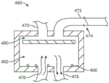
The cooling probe introduced into the interior of the balloon may include a number of different configurations that may assist in introducing the cryoablative fluid into the balloon. One such variation is that the shaft may have one or more cooling members that project from the distal end of the shaft at various angles. Another variation of the cooling probe may have a rotating base and a spray member positioned on a shaft. The spray member may have a mesh, grid, perforated, etc. surface such that cryoablative fluid introduced through the shaft may enter the rotating base and the spray member where it may be evenly distributed through the spray member and into the balloon interior for treatment.
The cooling probe positioned within the balloon may be configured in various ways, and may include other variations. The cooling probe assembly may include an exhaust conduit having an atraumatic tip and an imaging device, such as a hysteroscope, positioned therein. One or more support members or inserts may be positioned throughout the length of the chamber to provide structural support to the catheter and prevent it from collapsing, and a stylet support (e.g., flat wire, ribbon, etc.) may extend through the interior of the catheter.
The probe support may be supported within the chamber via an insert such that the probe support divides the chamber into a first channel and a second channel, wherein the cooling chamber may be positioned within the second channel along the probe support while the first channel may remain empty for optional insertion of a hysteroscope. Due to the thickness of the probe support relative to its width, the probe support may flex or bend in a single plane while remaining relatively rigid in a plane transverse to the plane.
The probe may further include one or more cooling chambers positioned within the second channel along the probe support. Since the cooling chamber is located along a second channel separated by the probe support, one or more windows or openings may be defined along the length of the probe support to allow any cryoablative fluid to pass through to diffuse through the entire chamber defined by the catheter. The number of cooling chambers may instead be three or more chambers, which terminate at different locations along the active portion.
The discharge catheter may also define one or more openings to allow the cryoablation fluid to discharge or exit from the interior of the catheter and into the interior of the balloon when the cryoablation fluid is introduced into and distributed throughout the catheter lumen.
One example of a treatment cycle using a two cycle procedure may include introducing a cryoablative fluid over a two minute treatment time, where surrounding tissue is frozen. Fluid may be aspirated from the balloon, and the tissue may be allowed to thaw over a five minute period. The cryoablative fluid can then be reintroduced and the tissue re-frozen over a period of two minutes, and then the fluid can be withdrawn again to allow the tissue to thaw over a period of five minutes. The tissue can be visually inspected via, for example, a hysteroscope to check for ablation coverage. If the tissue has been sufficiently ablated, the assembly can be removed from the uterus, otherwise the treatment cycle can be repeated as needed. In other alternatives, a single cycle may be utilized or more than two cycles may be utilized as needed to adequately treat tissue. Additionally, a minimum pressure of, for example, 40 to 80mmHg may optionally be maintained by freezing a liquid or by a gas (e.g., air, carbon dioxide, etc.) to keep the balloon and uterus open during the treatment cycle.
The balloon can be expanded in the uterus and in particular into the uterine horn by the first flushing in of a gas or liquid. Other mechanisms may also be used to facilitate balloon expansion. One variation may utilize one or more support arms extending from a support that may be deployed within the balloon. The support arms can be configured in a variety of ways, but they are shown in this example as being in a Y configuration. Another variation may include support arms incorporated into an elongate channel or pocket defined along the balloon itself.
In addition to the balloon itself and the use of the balloon to block the ostium, the internal uterine ostium and/or the external uterine ostium, the balloon or expandable liner can also be used to isolate the cryogenic fluid during delivery of the cryogenic fluid to the balloon to protect surrounding tissue structures, such as the cervix, from ablation.
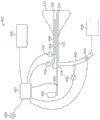
In controlling the above-described ablation treatment, the treatment assembly can be integrated into a single cooling system, completely contained within the handle assembly, or it can be separated into components, as desired or needed. In either case, the cooling system may generally include a microcontroller for monitoring and/or controlling parameters such as chamber temperature, chamber pressure, discharge pressure, etc.
A coolant reservoir (e.g., a nitrous oxide tank) may be fluidly coupled to the handle and/or the elongate shaft via a coolant valve, which may optionally be controlled by the microcontroller. A coolant reservoir may be in fluid communication with the interior of the cooling probe assembly and the balloon. Additionally, the vent chamber in communication with the elongated probe and having a backpressure valve may also include a pressure sensor, wherein one or both of the backpressure sensor and/or the valve may also be in communication with the microcontroller.
The present application also relates to the following aspects:
1) a tissue treatment system comprising:
a handle having a housing;
an elongate probe extending from the housing and having a distal tip and a flexible length;
a liner that distensibly encloses the probe;
at least one infusion chamber positioned through or along the elongate probe, wherein the infusion chamber defines one or more openings along its length; and
a controller configured to:
delivering a non-ablative fluid into an interior of the liner to expand the liner;
monitoring a condition of the liner;
delivering an ablative fluid into an interior of the liner via the infusion lumen;
evacuating the ablative fluid from the liner.
2) The tissue treatment system of 1), wherein the controller is configured to monitor the condition of the liner by monitoring the pressure in the liner over a period of time.
3) The system of 2), wherein the controller is further configured to monitor a condition of the liner by detecting whether a pressure within the interior of the liner remains above a set pressure for a predetermined period of time to determine whether a leak is present within the liner.
4) The tissue treatment system of 1), wherein the ablative fluid comprises a cryoablative liquid.
5) The tissue treatment system of 4), wherein the controller is configured to evacuate the ablative fluid from the liner after the cryoablative liquid becomes a gas.
6) The tissue treatment system of 1), wherein delivering the ablative fluid into the interior of the liner occurs after monitoring a condition of the liner.
7) The system of 1), further comprising at least one delivery lumen slidably positioned through or along the infusion lumen, wherein translation of the delivery lumen relative to the infusion lumen controls the number of unobstructed openings along the infusion lumen, thereby controlling the ablation length of the liner.
8) The tissue treatment system of 1), wherein the non-ablative fluid comprises ambient air.
9) The system of 1), wherein the controller is further configured to deliver ambient air into the interior of the liner at a predetermined pressure for a predetermined period of time prior to infusion of the ablative fluid.
10) The system of 1), wherein the controller is further configured to stop delivery of the ablative fluid into the interior of the liner.
11) The system of 10), wherein the controller is further configured to infuse air into the interior of the liner while the ablative fluid remains within the interior, and then to vent the liner to thaw tissue in contact with an exterior of the liner.
12) A method of treating tissue comprising:
positioning an elongate probe into a body cavity to be treated;
expanding a liner enclosing the probe into contact with the body cavity using a non-ablative fluid;
monitoring a fluid condition of the liner; and
infusing an ablative fluid through a delivery lumen such that the fluid enters into an infusion lumen and into the liner to contact the interior of the liner.
13) The method of 12), further comprising adjusting a position of the delivery chamber relative to the infusion chamber positioned through or along the elongate probe such that one or more openings defined along a length of the infusion chamber remain unobstructed by the delivery chamber.
14) The method of 13), wherein infusing the ablative fluid through the delivery lumen further comprises maintaining the liner at a pressure of up to 150mmHg and for a period of time of up to 150 seconds.
15) The method of 12), wherein monitoring a fluid condition of the liner comprises monitoring a pressure in the liner over a period of time.
16) The method of 12), further comprising detecting whether a pressure within the interior of the liner remains above 40mmHg over a period of 5 seconds to determine whether a leak is present within the liner.
17) The method of 12), wherein infusing the ablative fluid is controlled via a controller.
18) The method of 12), further comprising ceasing infusion of the ablative fluid into the interior of the liner.
19) The method of 12), wherein air is infused into the interior of the liner at a predetermined pressure and over a period of time prior to infusion of the ablative fluid.
20) The method of 12), further comprising detecting whether a pressure within the interior of the liner deviates by at least a predetermined pressure over a predetermined period of time to determine whether a leak is present within the liner.
21) The method of 12), further comprising infusing air into the interior of the liner at a predetermined pressure while the ablative fluid remains within the interior, and then venting the liner for a predetermined time of about 2 seconds to thaw tissue in contact with the exterior of the liner.
22) A method of ablating tissue, comprising:
positioning an elongate probe in a body cavity to be treated;
delivering a non-ablative gas into a liner enclosing the probe to expand the liner into contact with a tissue surface of the body cavity;
monitoring a condition of the liner;
infusing an ablative fluid in a liquid state along the probe through an infusion chamber and through one or more openings defined along a length of the infusion chamber;
spraying the ablative fluid against a wall of the liner such that the ablative fluid transitions from a state when ablating tissue to a gaseous state when cooling tissue in contact with the wall of the liner; and
evacuating the ablative fluid from the liner in the gaseous state.
23) The method of 22), wherein infusing further comprises adjusting a position of a delivery chamber relative to the infusion chamber such that the one or more openings defined along a length of the infusion chamber remain unobstructed by the delivery chamber.
24) The method of 22), wherein spraying further comprises reducing the temperature within the interior of the liner to about-89 ℃ within 6-7 seconds after spraying.
25) The method of 22), wherein spraying further comprises spraying the ablative fluid in a transverse or perpendicular direction relative to the probe.
26) The method of 22), wherein spraying further comprises coating the wall of the liner with the ablative fluid.
27) The method of 22), wherein delivering the non-ablative gas into the liner comprises infusing one or more jets of air into the liner until the liner conforms to the body cavity.
28) The method of 22), wherein infusing the ablative fluid comprises infusing a nitrous oxide or argon fluid into the interior of the liner.
29) The method of 22), further comprising monitoring a pressure of the interior of the liner while spraying the ablative fluid.
30) The method of 22), wherein monitoring the condition of the liner further comprises monitoring a pressure within the interior of the liner for detecting a leak.
31) A medical device for treating tissue of a body lumen with an ablative agent, the medical device comprising:
an elongate probe having a distal tip;
a liner distensibly enclosing the probe, the liner configured to expand and conform to the body lumen when a low pressure is applied within the liner, wherein a liner wall is configured to transfer energy between the tissue lumen and the ablative agent;
at least one infusion lumen extending from the elongate probe into the liner, the at least one infusion lumen having a plurality of infusion openings positioned along a length of the liner;
wherein the plurality of infusion openings are configured to direct flow of the ablative agent from the infusion lumen to a plurality of respective wall portions of the liner wall;
at least one delivery lumen slidingly positioned in the infusion lumen, wherein translation of the delivery lumen relative to the infusion lumen during flow of the ablative agent allows for selectively directing flow of the ablative agent through one or more of the plurality of openings so as to selectively ablate tissue in contact with one or more of the respective wall portions.
32) The system of 31), wherein the plurality of infusion openings are configured to direct flow of the ablative agent in a lateral direction relative to the infusion lumen.
33) The system of 31), wherein the plurality of infusion openings are configured to direct flow of the ablative agent in alternating directions relative to the infusion lumen.
34) The system of 31), wherein the plurality of infusion openings along the infusion lumen are defined opposite one another along the infusion lumen.
35) The system of 31), wherein the delivery lumen comprises a nitinol delivery tube slidingly positioned through the infusion lumen.
36) The system of 31), wherein the plurality of infusion openings comprise a plurality of patterned slots along an anterior surface and/or a posterior surface of the elongate probe.
37) The system of 36), wherein the elongate probe is configured to bend within a single plane via the one or more slots.
38) The system of 31), wherein the ablative agent comprises a cryoablative fluid, and the system further comprises a reservoir of the cryoablative fluid in fluid communication with the delivery chamber.
39) The system of 38), wherein the cryoablative fluid comprises nitrous oxide.
40) The system of 31), further comprising a sheath assembly slidably positioned over the elongate probe.
41) The system of 31), further comprising one or more transmitters and receivers positioned on the elongate probe.
42) The system of 31), further comprising a pump in fluid communication with an interior of the liner.
43) The system of 42), further comprising a valve fluidly coupled to the pump and reconfigurable to divert positive and negative pressures from the pump to the liner interior.
44) The system of 31), further comprising one or more pressure sensors along the elongate probe.
45) The system of 31), wherein the liner comprises at least two tapered portions extending from a distal end of the elongate probe such that the tapered portions are configured to contact a corresponding uterine horn.
46) A method of treating tissue comprising:
positioning an elongate probe in a body cavity to be treated;
expanding a liner enclosing the probe to touch the body cavity, wherein the liner comprises at least one infusion chamber having a plurality of infusion openings positioned along a length of the liner, the plurality of infusion openings configured to direct a flow of fluid to a plurality of respective wall portions of the liner, wherein each of the infusion openings is associated with at least one of the plurality of respective wall portions;
delivering an ablative agent into the infusion lumen through a delivery lumen; and
adjusting a treatment length of the liner by translating the delivery chamber relative to the infusion chamber to selectively direct flow through one or more of the infusion openings and control delivery of the ablative agent to one or more of the respective wall portions of the liner.
47) The method of 46), further comprising withdrawing the cryoablative fluid from the interior of the liner.
48) The method of 46), wherein expanding the liner comprises slowly adding a non-ablative fluid into the liner until the liner conforms to the body cavity.
49) The method of 46), wherein translating the delivery chamber comprises translating the delivery chamber through the infusion chamber to selectively obstruct the one or more openings.
50) The method of 46), wherein delivering the ablative agent comprises delivering a cryoablative fluid into the interior of the liner.
51) The method of 46), further comprising stopping delivery of the ablative agent and evacuating the interior of the liner through the elongate probe.
52) The method of 51), wherein evacuating the interior of the liner comprises opening and closing a valve in fluid communication between a pump and the interior of the liner.
53) The method of 46), wherein expanding a liner further comprises emitting one or more signals from a distal end of the elongate probe to detect a position of the probe relative to the body cavity.
54) The method of 46), wherein expanding a liner further comprises emitting one or more signals along the length of the probe to detect expansion of the body cavity.
55) The method of 46), wherein infusing a cryoablative fluid comprises maintaining an isolated annular space or gap between a sheath assembly and the interior of the elongate probe.
56) The method of 46), further comprising monitoring a pressure of the interior of the liner while infusing the cryoablative fluid.
57) The method of 46), further comprising monitoring a temperature of the body chamber while infusing the cryoablative fluid.
58) The method of 46), wherein expanding the liner further comprises detecting a leak.
59) A tissue treatment system comprising:
an elongate probe having a distal tip and a flexible length;
at least one infusion chamber positioned through or along the elongate probe, wherein the infusion chamber defines one or more openings along its length;
at least one delivery lumen slidingly positioned through or along the infusion lumen, wherein translation of the delivery lumen relative to the infusion lumen controls the number of unobstructed openings along the infusion lumen; and
a liner that distensibly encloses the probe.
60) The system of 59), wherein the elongate probe defines an exit chamber for ablative fluid.
61) The system of 59), wherein the infusion chamber and the delivery chamber are in fluid communication with each other.
62) The system of 59), wherein the one or more openings along the infusion lumen are defined opposite one another along the infusion lumen.
63) The system of 59), wherein the delivery lumen comprises a nitinol delivery tube slidingly positioned through the infusion lumen.
64) The system of 59), wherein the elongate probe defines a plurality of patterned slots along an anterior and/or posterior surface.
65) The system of 64), wherein the elongate probe is configured to bend within a single plane via the one or more slots.
66) The system of 59), further comprising a reservoir of cryoablative fluid in fluid communication with the delivery chamber.
67) The system of 66), wherein the cryoablative fluid comprises nitrous oxide.
68) The system of 59), wherein the elongated chamber defines an effective treatment portion near or at the distal tip.
69) The system of 59), further comprising a sheath assembly slidably positioned over the elongate probe.
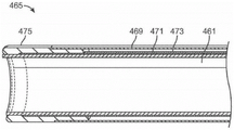
70) The system of 69), wherein the sheath assembly comprises an inner sheath and an outer sheath defining an annular space or gap.
71) The system of 59), further comprising one or more transmitters and receivers positioned on the elongate probe.
72) The system of 59), further comprising a pump in fluid communication with the liner interior.
73) The system of 72), further comprising a valve fluidly coupled to the pump and reconfigurable to divert positive and negative pressures from the pump to the liner interior.
74) The system of 59), further comprising one or more pressure sensors along the elongate probe.
75) The system of 59), wherein the liner comprises at least two tapered portions extending from a distal end of the elongate probe such that the tapered portions are configured to contact a corresponding uterine horn.
76) A method of treating tissue comprising:
positioning an elongate probe into a body cavity to be treated;
expanding a liner enclosing the probe to touch the body cavity;
adjusting a position of a delivery chamber relative to an infusion chamber positioned through or along the elongate probe such that one or more openings defined along a length of the infusion chamber remain unobstructed by the delivery chamber; and
infusing cryoablative fluid through the delivery chamber such that the fluid passes through unobstructed openings into the infusion chamber and touches the interior of the liner.
77) The method of 76), further comprising withdrawing the cryoablative fluid from the interior of the liner.
78) The method of 76), wherein expanding a liner comprises infusing one or more jets of air into the liner until the liner conforms to the body cavity.
79) The method of 76), wherein adjusting the position of the delivery chamber comprises translating the delivery chamber through the infusion chamber to selectively obstruct the one or more openings.
80) The method of 76), wherein infusing cryoablative fluid comprises infusing nitrous oxide into the interior of the liner.
81) The method of 76), further comprising stopping infusion of the cryoablative fluid and evacuating the interior of the liner through the elongate probe.
82) The method of 81), wherein evacuating the interior of the liner comprises switching a valve in fluid communication between a pump and the interior of the liner.
83) The method of 76), wherein expanding a liner further comprises emitting one or more signals from a distal end of the elongate probe to detect a position of the probe relative to the body cavity.
84) The method of 76), wherein expanding a liner further comprises emitting one or more signals along the length of the probe to detect expansion of the body cavity.
85) The method of 76), wherein infusing a cryoablative fluid comprises maintaining an isolated annular space or gap between a sheath assembly and the interior of the elongate probe.
86) The method of 76), further comprising monitoring a pressure of the interior of the liner while infusing the cryoablative fluid.
87) The method of 76), further comprising monitoring a temperature of the body chamber while infusing the cryoablative fluid.
88) The method of 76), wherein expanding the liner further comprises detecting a leak.
89) A method of removing a liner from a tissue surface, comprising:
positioning an elongate probe into a body cavity to be treated;
expanding a liner enclosing the probe to touch the tissue surface of the body lumen;
infusing a cryoablative fluid or gas through the elongate probe and within the interior of the liner such that the tissue surface contacting the liner is ablated;
applying a negative pressure within the interior of the liner such that the liner is pulled away from a tissue surface in a normal direction.
90) The method of 89), wherein positioning an elongate probe comprises introducing the elongate probe into a uterine cavity.
91) The method of 89), wherein expanding a liner comprises infusing one or more jets of air into the interior of the liner until the liner conforms to the body lumen.
92) The method of 89), wherein infusing a cryoablative fluid or gas comprises infusing nitrous oxide into the interior of the liner.
93) The method of 89), wherein applying negative pressure further comprises withdrawing the cryoablative fluid or gas from the interior of the liner.
94) The method of 89), wherein applying negative pressure further comprises stopping infusion of the cryoablative fluid and evacuating the interior of the liner through the elongate probe.
95) The method of 94), wherein evacuating the interior of the liner comprises opening and closing a valve in fluid communication between a pump and the interior of the liner.
96) The method of 89), wherein infusing a cryoablative fluid or gas comprises maintaining an isolated annular space or gap between a sheath assembly and the interior of the elongate probe.
97) The method of 89), further comprising monitoring a pressure of the interior of the liner while infusing the cryoablative fluid or gas.
98) The method of 89), further comprising monitoring a temperature of the body lumen while infusing the cryoablative fluid or gas.
99) The method of 89), wherein expanding the liner further comprises detecting a leak.
100) The method of 89), further comprising introducing a fluid or air into the interior of the liner to warm the liner after infusing the cryoablative fluid or gas.
101) The method of 89), further comprising heating the interior of the liner to warm the liner after infusing the cryoablative fluid or gas.
102) A liner configured for expansion within a uterine cavity, comprising:
a flexible membrane configured to have a flattened shape when in a non-expanded configuration and a contoured shape to conform to the uterine cavity when in an expanded configuration,
wherein the membrane in the expanded configuration has a length that tapers from a first width to a second width that is smaller than the first width and that is sized to receive an instrument therethrough and into an interior of the membrane,
wherein the first width comprises a first curved portion and a second curved portion opposite the first curved portion such that the membrane defines a first region having a first radius between the first curved portion and the second curved portion,
wherein the membrane further defines a second region adjacent the first curved portion and the second curved portion having a second radius different from the first radius, and
wherein the film also defines, adjacent to the second region, a third region having a third radius opposite the second radius.
103) The liner of 102), wherein the film is configured to be corrugated to facilitate folding of the film for deployment.
104) The liner of 102), wherein the film has a uniform thickness.
105) The liner of 102), wherein the film has a non-uniform thickness.
106) The liner of 102), wherein the film has a length of about 3.5 inches.
107) The liner of 102), wherein the first width of the film is about 2.4 inches.
108) The liner of 102), wherein the second width of the film is about 0.3 inches.
109) The liner of 102), wherein the film comprises polyurethane.
110) The liner of 102), further comprising an elongated shaft, the second width of the film being affixed to the elongated shaft.
111) The liner of claim 110), further comprising:
an elongated probe having a distal tip and a flexible length, the elongated probe being positionable across the second width and into the interior of the membrane,
at least one infusion chamber positioned through or along the elongate probe, wherein the infusion chamber defines one or more openings along its length; and
at least one delivery lumen slidingly positioned through or along the infusion lumen, wherein translation of the delivery lumen relative to the infusion lumen controls the number of unobstructed openings along the infusion lumen.
112) The liner of 111), wherein the elongate probe defines an exit chamber for ablative fluid.
113) The liner of 111), wherein the infusion chamber and the delivery chamber are in fluid communication with each other.
114) The liner of 111), further comprising a reservoir of cryoablative fluid or gas in fluid communication with the delivery chamber.
115) The liner of 102), wherein the first and second curved portions are each configured to contact a corresponding uterine horn.
116) A handheld tissue treatment system comprising:
a handle having a housing;
an elongate probe having a distal tip and a flexible length, the elongate probe extending from the handle;
at least one infusion chamber positioned through or along the elongate probe, wherein the infusion chamber defines one or more openings along its length;
at least one delivery lumen slidingly positioned through or along the infusion lumen, wherein translation of the delivery lumen relative to the infusion lumen controls the number of unobstructed openings along the infusion lumen;
a liner that distensibly encloses the probe; and
a reservoir containing a cryoablative fluid or gas, the reservoir being integrated into or along the housing and in fluid communication with the at least one infusion chamber.
117) The system of 116), wherein the elongate probe defines an exhaust chamber for the cryoablative fluid or gas.
118) The system of 116), wherein the infusion chamber and delivery chamber are in fluid communication with each other.
119) The system of 116), wherein the one or more openings along the infusion lumen are defined opposite one another along the infusion lumen.
120) The system of 116), wherein the delivery lumen comprises a nitinol delivery tube slidingly positioned through the infusion lumen.
121) The system of 116), wherein the elongate probe defines a plurality of patterned slots along an anterior and/or posterior surface.
122) The system of 121), wherein the elongate probe is configured to bend within a single plane via the one or more slots.
123) The system of 116), wherein the cryoablative fluid or gas comprises nitrous oxide.
124) The system of 116), wherein the elongated chamber defines an effective treatment portion near or at the distal tip.
125) The system of 116), further comprising a sheath assembly slidably positioned over the elongate probe.
126) The system of 116), further comprising a pump in fluid communication with an interior of the liner.
127) The system of 116), wherein the liner comprises at least two tapered portions extending from a distal end of the elongate probe such that the tapered portions are configured to contact a corresponding uterine horn.
128) A method of treating tissue comprising:
positioning an elongate probe extending from a handle in a body cavity to be treated;
expanding a liner enclosing the probe to touch the body cavity;
adjusting a position of a delivery chamber relative to an infusion chamber positioned past or along the elongate probe such that one or more openings defined along a length of the infusion chamber remain unobstructed by the delivery chamber; and
infusing cryoablative fluid or gas from a reservoir through the delivery chamber such that the fluid or gas enters the infusion chamber through an unobstructed opening and touches the interior of the liner, wherein the reservoir is integrated into or along the handle.
129) The method of 128), further comprising withdrawing the cryoablative fluid or gas from the interior of the liner.
130) The method of 128), wherein expanding a liner comprises infusing one or more jets of air into the liner until the liner conforms to the body cavity.
131) The method of 128), wherein adjusting the position of the delivery chamber comprises translating the delivery chamber through the infusion chamber to selectively obstruct the one or more openings.
132) The method of 128), wherein infusing a cryoablative fluid or gas comprises infusing nitrous oxide into the interior of the liner.
133) The method of 128), further comprising stopping infusion of the cryoablative fluid or gas and evacuating the interior of the liner through the elongate probe.
134) The method of 128), further comprising monitoring a pressure of the interior of the liner while infusing the cryoablative fluid or gas.
135) The method of 128), wherein expanding the liner further comprises detecting a leak.
136) A tissue treatment system comprising:
a handle having a housing;
an elongate probe extending from the housing and having a distal tip and a flexible length;
a liner that distensibly encloses the probe;
at least one infusion chamber positioned through or along the elongate probe, wherein the infusion chamber defines one or more openings along its length; and
a controller programmed to infuse a cryoablative fluid or gas into the interior of the liner via the infusion chamber at a pressure of up to 150mmHg and for a period of time of up to 150 seconds.
137) The system of 136), further comprising at least one delivery lumen slidably positioned through or along the infusion lumen, wherein translation of the delivery lumen relative to the infusion lumen controls the number of unobstructed openings along the infusion lumen.
138) The system of 136), wherein the controller is further programmed to infuse air into the interior of the liner at a pressure of up to 85mmHg and for a time period of up to 20 seconds prior to infusing the cryoablative fluid or gas.
139) The system of 136), wherein the controller is further programmed to detect whether the pressure within the interior of the liner remains above 40mmHg over a period of 5 seconds to determine whether a leak is present in the liner.
140) The system of 136), wherein the controller is further programmed to detect whether the pressure within the interior of the liner deviates by 20mmHg or more over a period of 3 seconds to determine whether a leak is present within the liner.
141) The system of 136), wherein the controller is further programmed to infuse the cryoablative fluid or gas until the temperature of the interior of the liner is about-89 ℃.
142) The system of 136), wherein the controller is further programmed to stop infusing the cryoablative fluid or gas into the interior of the liner.
143) The system of 142), wherein the controller is further programmed to infuse air into the interior of the liner at a pressure of about 10mmHg while the cryoablation fluid or gas remains within the interior, and then to ventilate for about 2 seconds to thaw tissue in contact with the exterior of the liner.
144) The system of 136), wherein the elongate probe defines a discharge chamber for an ablative fluid.
145) The system of 136), wherein the one or more openings along the infusion lumen are defined opposite one another along the infusion lumen.
146) The system of 137), further comprising a reservoir of cryoablative fluid in fluid communication with the delivery chamber.
147) The system of 146), wherein the cryoablative fluid comprises nitrous oxide or argon.
148) The system of 136), further comprising a pump in fluid communication with an interior of the liner.
149) A method of treating tissue comprising:
positioning an elongate probe into a body cavity to be treated;
expanding a liner enclosing the probe to touch the body cavity;
adjusting a position of a delivery chamber relative to an infusion chamber positioned past or along the elongate probe such that one or more openings defined along a length of the infusion chamber remain unobstructed by the delivery chamber;
infusing cryoablative fluid or gas through the delivery chamber at a pressure of up to 150mmHg and over a period of up to 150 seconds, such that the fluid passes through unobstructed openings into the infusion chamber and touches the interior of the liner.
150) The method of 149), wherein the infusion of the cryoablative fluid or gas is controlled via a controller.
151) The method of 149), further comprising ceasing the infusion of the cryoablative fluid or gas into the interior of the liner.
152) The method of 151), wherein prior to infusing cryoablative fluid or gas, further comprising infusing air into the interior of the liner at a pressure of up to 8.5mmHg and for a period of up to 20 seconds.
153) The method of 149), further comprising detecting whether a pressure within the interior of the liner remains above 40mmHg over a period of 5 seconds to determine whether a leak is present within the liner.
154) The method of 149), further comprising detecting whether the pressure within the interior of the liner deviates by 20mmHg or more over a period of 3 seconds to determine whether a leak is present within the liner.
155) The method of 149), wherein infusing a cryoablative fluid or gas comprises not stopping the infusion until the temperature of the interior of the liner is about-89 ℃.
156) The method of 149), further comprising infusing air into the interior of the liner at a pressure of about 10mmHg while the cryoablative fluid or gas remains within the interior, and then venting for about 2 seconds to thaw tissue in contact with the exterior of the liner.
157) A method of treating tissue comprising:
positioning an elongate probe into a body cavity to be treated;
expanding a liner enclosing the probe to touch the body cavity;
adjusting a position of a delivery chamber relative to an infusion chamber positioned past or along the elongate probe such that one or more openings defined along a length of the infusion chamber remain unobstructed by the delivery chamber;
infusing a cryoablative fluid or gas through the delivery chamber at a restricted flow rate such that the fluid enters the infusion chamber through an unobstructed opening and touches the interior of the liner such that the temperature within the interior of the liner decreases to-89 ℃ within 6 to 7 seconds of introducing the fluid or gas.
158) The method of 157), wherein infusing a cryoablative fluid or gas comprises infusing at a pressure of up to 150mmHg and over a period of up to 150 seconds.
159) The method of 157), wherein the infusion of the cryoablative fluid or gas is controlled via a controller.
160) The method of 157), further comprising ceasing infusion of the cryoablative fluid or gas into the interior of the liner.
161) The method of 160), wherein prior to infusing cryoablative fluid or gas, further comprising infusing air into the interior of the liner at a pressure of up to 85mmHg and for a period of up to 20 seconds.
162) The method of 157), further comprising detecting whether a pressure within the interior of the liner remains above 40mmHg over a period of 5 seconds to determine whether a leak is present in the liner.
163) The method of 157), further comprising detecting whether a pressure within the interior of the liner deviates by 20mmHg or more over a period of 3 seconds to determine whether a leak is present within the liner.
164) The method of 157), further comprising infusing air into the interior of the liner at a pressure of about 10mmHg while the cryoablative fluid or gas remains within the interior, and then venting for about 2 seconds to thaw tissue in contact with the exterior of the liner.
165) A method of ablating tissue, comprising:
positioning an elongate probe into a body cavity to be treated;
expanding a liner enclosing the probe to touch a tissue surface of the body cavity;
infusing cryoablative fluid along the probe through an infusion chamber and through one or more openings defined along the length of the infusion chamber;
spraying the cryoablative fluid within the interior of the liner and contacting the cryoablative fluid against the wall of the liner; and
cooling tissue in contact with the liner by absorbing heat from the tissue surface, wherein the heat is conducted through the liner and into the fluid such that the fluid evaporates into gaseous form within the liner.
166) The method of 165), further comprising withdrawing the gas from the interior of the liner via the probe.
167) The method of 165), wherein infusing further comprises adjusting a position of a delivery chamber relative to the infusion chamber such that the one or more openings defined along a length of the infusion chamber remain unobstructed by the delivery chamber.
168) The method of 165), wherein spraying further comprises reducing the temperature within the interior of the liner to about-89 ℃ within 6-7 seconds after spraying.
169) The method of 165), wherein spraying further comprises spraying the fluid in a lateral or perpendicular direction relative to the probe.
170) The method of 165), wherein spraying further comprises coating the wall of the liner with the sprayed fluid.
171) The method of 165), further comprising withdrawing the gas from the interior of the liner.
172) The method of 171), wherein withdrawing the gas comprises switching a valve in fluid communication between a pump and the interior of the liner.
173) The method of 165), wherein spraying further comprises spraying the fluid over a period of time of up to 150 seconds.
174) The method of 165), wherein expanding a liner comprises infusing one or more jets of air into the liner until the liner conforms to the body cavity.
175) The method of 165), wherein infusing cryoablative fluid comprises infusing nitrous oxide or argon into the interior of the liner.
176) The method of 165), further comprising stopping infusion of the cryoablative fluid and evacuating the interior of the liner through the elongate probe.
177) The method of 165), wherein infusing a cryoablative fluid comprises maintaining an isolated annular space or gap between a sheath assembly and the interior of the elongate probe.
178) The method of 165), further comprising monitoring a pressure of the interior of the liner while spraying the cryoablative fluid.
179) The method of 165), further comprising monitoring a temperature of the body chamber while spraying the cryoablative fluid.
180) The method of 165), further comprising monitoring pressure within the interior of the liner for detecting a leak.
181) A tissue treatment system comprising:
a handle having a housing;
an elongate probe extending from the housing and having a distal tip and a flexible length;
a liner that distensibly encloses the probe;
at least one infusion chamber positioned through or along the elongate probe, wherein the infusion chamber defines one or more openings along its length;
one or more pressure sensors within an interior of the liner; and
a controller in communication with the one or more pressure sensors, wherein the controller is programmed to monitor pressure as cryoablative fluid or gas is infused into the interior via the infusion chamber.
182) The system of 181), wherein the controller is further programmed to suspend infusion of the cryoablative fluid or gas when the monitored pressure exceeds 150 mmHg.
183) The system of 181), further comprising one or more actuatable valves in communication with the controller, wherein the one or more actuatable valves are configured to stop infusion of the cryoablative fluid when triggered by the controller.
184) The system of 181), wherein the one or more pressure sensors are positioned along the elongate probe for monitoring pressure within the interior of the liner.
185) The system of 181), wherein the one or more pressure sensors are positioned near or at a tip of the elongate probe.
186) The system of 181), wherein the one or more pressure sensors are positioned in fluid communication with the infusion chamber.
187) The system of 181), further comprising one or more flow sensors in communication with the controller.
188) The system of 181), wherein a delivery line in fluid communication with the infusion chamber is sized to limit a flow rate through the delivery line.
189) The system of 181), further comprising one or more temperature sensors in communication with the controller.
190) The system of 181), further comprising an indicator or alarm in communication with the controller, wherein the indicator or alarm is configured to alert a user when a predetermined pressure is exceeded within the interior of the liner.
191) The system of 181), wherein the controller is further programmed to periodically transmit a signal to the system.
192) The system of 181), further comprising a relief valve in communication with the interior of the liner, wherein the relief valve is configured to open if a predetermined pressure is exceeded.
193) The system of 181), further comprising at least one delivery lumen slidably positioned through or along the infusion lumen, wherein translation of the delivery lumen relative to the infusion lumen controls the number of unobstructed openings along the infusion lumen.
194) The system of 181), wherein the controller is further programmed to detect whether the pressure within the interior of the liner deviates by 20mmHg or more over a period of 3 seconds to determine whether a leak is present in the liner.
195) The system of 181), wherein the controller is further programmed to infuse the cryoablative fluid or gas at a predetermined temperature or pressure of the interior of the liner.
196) The system of 181), wherein the cryoablative fluid or gas comprises nitrous oxide or argon.
197) The system of 181), further comprising a pump in fluid communication with an interior of the liner.
198) A method of treating tissue comprising:
positioning an elongate probe into a body cavity to be treated;
expanding a liner enclosing the probe to touch the body cavity;
adjusting a position of a delivery chamber relative to an infusion chamber positioned past or along the elongate probe such that one or more openings defined along a length of the infusion chamber remain unobstructed by the delivery chamber;
infusing a cryoablative fluid or gas through the delivery chamber such that the fluid enters into the infusion chamber and touches the interior of the liner; and
monitoring one or more pressure sensors while infusing the cryoablative fluid or gas into the interior via the infusion chamber.
199) The method of 198), wherein positioning comprises positioning the elongate probe into a uterine cavity.
200) The method of 198) further comprising stopping infusion of the cryoablative fluid or gas if the pressure exceeds a predetermined level.
201) The method of 200), wherein stopping comprises pausing the infusion if the pressure within the liner exceeds 150 mmHg.
202) The method of 200), wherein ceasing comprises actuating one or more valves to cease infusion of the cryoablative fluid or gas.
203) The method of 198), wherein monitoring comprises sensing pressure via one or more pressure sensors positioned along the elongate probe.
204) The method of 198), further comprising actuating an indicator or alarm when a predetermined pressure is exceeded within the interior.
205) The method of 198), further comprising actuating a pressure relief valve when a predetermined pressure is exceeded within the interior.
206) The method of 198), further comprising determining whether the pressure within the interior deviates by 20mmHg or more over a period of 3 seconds to determine whether a leak is present in the liner.
207) The method of 198) wherein infusing a cryoablative fluid or gas comprises infusing at a predetermined temperature or pressure within the interior of the liner.
208) The method of 198) further comprising monitoring a flow rate of the cryoablative fluid or gas infused into the interior.
209) The method of 198) further comprising restricting a flow rate through a delivery line in fluid communication with the delivery chamber.
210) The method of 198) further comprising controlling a back pressure of the cryoablative fluid or gas expelled from the interior.
211) The method of 198) further comprising heating or cooling the temperature of the fluid or gas prior to infusing the cryoablative fluid or gas through the delivery chamber.
Drawings
For purposes of the figures and preferred embodiments, the esophagus and uterus will be shown in use. However, the devices and methods may be applied to any body cavity/chamber that may be visualized using an endoscope or other visualization mechanism.
Fig. 1 shows an example of an instrument advanced through an endoscope, such as a transnasal or transoral inserted scope.
Fig. 2 shows an example of an instrument being advanced through the working channel of a transnasal endoscope.
Fig. 3 shows an example of an instrument attached to a logic controller.
Fig. 4 shows an example of an instrument placed through the working channel of a transnasal endoscope and deployed within the esophagus for treatment.
FIG. 5 shows an example of an instrument advanced alongside an endoscope.
Fig. 6A-6C illustrate the instrument being introduced endoscopically and deployed within the esophagus for treatment.
Fig. 7A-7C illustrate an example of an instrument introduced endoscopically for insertion into the bladder.
Fig. 8A to 8C show an example of an apparatus for preparing a treatment area with a pre-treatment lavage solution prior to treatment.
Figure 9 shows an example of a distal occluder having an umbrella shape deployed for treatment adjacent the gastroesophageal junction.
Figure 10 shows another example of an endoscope balloon sheath with a distal occluder expanded distal of the gastroesophageal junction for treatment.
Fig. 11 shows another example in which treatment fluid is introduced between deployed balloons for treatment.
Fig. 12 shows another example of a size adjustable balloon instrument for treating the esophagus.
Fig. 13A and 13B illustrate another example of a single balloon instrument for ablation treatment within the uterus and/or endometrium layers.
Fig. 14A and 14B show another example of a conductive mesh/cage deployed for cryoablation therapy.
Fig. 15 illustrates another example of an external cervical os occlusion instrument.
Fig. 16 illustrates another example of an internal cervical os occlusion instrument.
Fig. 17A and 17B illustrate another example of an instrument having a deployable low pressure compliant balloon for uterine cryotherapy.
Fig. 18A-18D illustrate another example of a compliant balloon that may also be partially or completely filled with a conductive material for use in cryoablation therapy.
Fig. 19 illustrates another example of a cooling probe having one or more cooling members protruding from a distal end of a shaft.
FIG. 20 illustrates another example of a cooling probe having a rotatable base and a spray member.
Fig. 21A shows a side view of an integrated therapeutic assembly.
Fig. 21B shows an example of an assembly advanced transcervically and into the uterus, where the sheath can be retracted via the handle assembly to deploy the balloon.
Fig. 21C shows a perspective view of a cryoablation assembly with a handle assembly that can integrate electronics and a pump assembly within the handle itself.
Fig. 21D illustrates a perspective exploded view of the handle assembly showing some of the components that may be integrated within the handle.
Fig. 21E shows an example of system operation during the pre-treatment bulge procedure.
Fig. 21F shows an example of system operation during a treatment procedure.
Fig. 21G shows an example of system operation during the defrosting and draining process.
Fig. 22A shows a side view of a system that allows for adjustable positioning of a balloon along the length of a shaft.
Fig. 22B shows a side view of the balloon inverted within the shaft lumen for delivery.
23A and 23B show perspective and side views, respectively, of another example of a cooling probe assembly having a flat wire integrated through the probe.
FIG. 24 shows a perspective view of a cooling probe assembly having one or more openings defined along the probe assembly.
Fig. 25A and 25B show end views of cross-sections of the cooling probe and the distal end of the probe.
26A-26L illustrate perspective views of various tubular members that may be used to cool the probe assembly.
27A and 27B illustrate perspective views of a cooling probe assembly utilizing one or more discrete ring members coupled to each other in a straight line.
28A and 28B show cross-sectional end views of another variation of a cooling probe assembly coupled via a cover and/or insert member.
FIG. 29 shows a perspective view of another variation of a cooling probe assembly having one or more insert members coupled along a coiled spring body.
Fig. 30A and 30B show cross-sectional side views of another variation of an insert member supported along a spring body.
FIG. 31 shows a detailed side view of a variation of the pivotable cooling chamber body.
FIG. 32 shows a side view of another variation of one or more insert members with an integrated cover.
Fig. 33 shows a side view of another variation of one or more insert members with attached slidable joints.
Figure 34 shows a side view of another variation of a spring body having one or more cooling chambers attached directly to the spring.
Figure 35 shows a side view of another variation of a spring body having one or more insert members.
FIG. 36 shows a side view of another variation of a spring body having one or more cooling chambers and a secondary chamber.
Figure 37 shows a cross-sectional end view of a variation of the secondary chamber.
Fig. 38A and 38B show perspective views of another variation of a cooling probe utilizing a main delivery line and at least two side delivery lines.
FIG. 38C shows a detailed view of a side delivery line having an adjustable mandrel slidably positioned therein.
FIG. 39 shows a cross-sectional side view of another variation of a cooling probe assembly in which the main delivery line and the side delivery line are in fluid communication through a common chamber.
Fig. 40A and 40B show cross-sectional end views of variations of the discharge chamber and corresponding cooling chamber.
FIG. 41 shows a cross-sectional side view of another variation of a cooling probe assembly with a single inlet line and a single delivery line.
Figure 42 shows a cross-sectional side view of a cooling probe assembly inserted within a balloon within a uterus.
Fig. 43A and 43B show side views of various examples of side delivery lines having openings aligned in different directions.
FIG. 44 shows a side view of a cooling probe variation with a shear window for facilitating visualization.
Fig. 45 shows a side view of an example of a balloon having one or more support arms extendable within the balloon.
Fig. 46 shows a side view of another example of a balloon having one or more support arms attached to a cooling probe assembly.
Fig. 47 shows a side view of another example of a balloon having one or more support arms that also define one or more openings for delivering a cryoablation fluid.
Fig. 48 shows a side view of another example of a balloon having one or more support arms positioned within an elongate channel along an interior of the balloon.
Fig. 49A and 49B show cross-sectional side views of another variation of a cooling probe utilizing a single infusion line in combination with a translatable delivery line.
Fig. 50A and 50B show top and perspective views of a dilation liner having four pairs of open delivery ports exposed in a apposition direction.
Fig. 50C shows a perspective view of an expansion liner with additional open delivery ports exposed along an anterior portion of the liner.
Figure 51A shows a variation of a probe that includes an emitter to facilitate positioning of the probe within a liner.
Figure 51B shows another variation of a probe that includes one or more emitters to monitor the dilation of a tissue cavity.
Fig. 52A and 52B show schematic illustrations of a system utilizing a 5-port, 2-position, 4-way valve.
Fig. 53A-53C show schematic illustrations of a system utilizing a non-reversible pump for both expansion and contraction.
Fig. 54A and 54B show top and perspective views of a liner showing the curved features of the liner when flattened and expanded and then deployed in a uniform manner.
Fig. 54C shows a perspective view of a liner that can be corrugated in a uniform manner to fold and collapse.
Fig. 55A and 55B show side and top views of a probe configured to be flexed in the anterior and posterior directions.
Fig. 55C shows a perspective view of a probe having multiple probe portions (e.g., four portions in this variation) separated by H-shaped slots.
Fig. 56A and 56B show perspective and detailed cross-sectional views of the sheathing assembly.
Fig. 56C shows a cross-sectional view of a sheath assembly containing a sensor (e.g., a temperature sensor).
Fig. 57 shows a variation of a sheath carrier tube that slides through the sheath carrier assembly and then attaches to a slider base stop assembly that is positioned within the handle assembly.
FIG. 58 shows a detailed perspective view of the connection between the sheath carrier tube and the slider base stop assembly.
Fig. 59A and 59B illustrate how the slider base stop assembly can be advanced distally or proximally relative to the handle assembly to expose the probe length.
FIG. 60 shows a perspective view of one or more optional pressure sensing lines included along the probe.
Fig. 61 shows a side view of an example of an expandable liner or balloon positioned along an outer distal surface of a sheath.
Fig. 62 shows a side view of another example of an expandable liner or balloon positioned along an inner distal surface of a sheath.
Fig. 63 illustrates a side view of another example in which an expandable foam may be deployed via an outer sheath.
Fig. 64 shows a side view of another example where a heating element may be positioned along an inner or outer surface of an elongated shaft.
Fig. 65 illustrates a side view of another example in which an annular balloon can be inflated along a sheath or shaft to isolate surrounding cervical tissue or to ensure fixed placement of the shaft and/or balloon during treatment.
FIG. 66 shows a cross-sectional side view of another variation in which an outer sheath may be formed as an expandable structure.
Fig. 67A and 67B show side views of variations of outer sheaths having reconfigurable distal ends.
Fig. 68 shows a side view of another variation of a balloon positioned along an outer surface of an outer sheath.
FIG. 69 shows a cross-sectional side view of a variation of the double sheath design.
Fig. 70A and 70B show cross-sectional detail views of the seal between the inner and outer sheaths.
FIG. 71 shows a partial cross-sectional side view of another double sheath variation with an expandable balloon contained between the sheaths.
Fig. 72 shows a side view of another variation of a jacket with a reinforcing structure.
Fig. 73 shows a cross-sectional side view of another variation of an outer sheath having an adjustable balloon member.
Fig. 74A and 74B show cross-sectional side views of another variation of an outer sheath having a reconfigurable distal end.
Fig. 75 shows a cross-sectional side view of a reconfigurable distal end having one or more lubricated surfaces.
Fig. 76 shows a partial cross-sectional side view of another variation where the reconfigurable distal end can be attached as a separate component.
Fig. 77 shows a cross-sectional side view of another variation, wherein the distal end of the cooling probe has a tapered distal end.
FIG. 78 shows a side view of another variation of an outer sheath having a radially expandable portion.
Fig. 79A and 79B show cross-sectional side views of variations of locking mechanisms for expandable portions.
Fig. 80A and 80B show cross-sectional side views of illustrative examples of eccentric linkages.
Fig. 81 shows a cross-sectional side view of another variation of an outer sheath having one or more distal cam members.
Fig. 82 illustrates a cross-sectional side view of one or more cam members deployed to their expanded configuration and secured against cervical tissue.
Fig. 83 shows a cross-sectional side view of another variation in which a camming distal end is positioned over a tapered outer sheath.
Fig. 84 shows a side view of an example of how the outer sheath and the member may be initially deployed and secured to separately advance the cooling probe set.
FIG. 85 shows a side view of another variation in which the outer jacket is configured as a corrugated structure.
Fig. 86 shows a partial cross-sectional side view of another variation of an outer sheath having an inflatable balloon along an inner surface.
Fig. 87 shows a partial cross-sectional side view of another variation of an outer sheath having an inflatable balloon along an outer surface.
Fig. 88A-88D show cross-sectional end views of variations of the outer sheath with integrated features to provide further isolation to surrounding tissue.
Fig. 89 shows an exemplary schematic of a treatment assembly integrated into a single cooling system.
Fig. 90A and 90B illustrate an instrument for closing the vent flow path to facilitate liner integrity checks and also to increase pressure within the uterine cavity.
FIGS. 91A and 91B show a schematic side view of a flapper valve and a top view of a gasket within the flapper valve for maintaining a venting back pressure within the system.
Fig. 91C-91E show schematic side views illustrating an example of flapper valve operation.
FIGS. 92A and 92B show schematic side views of another variation of a flapper valve.
Fig. 93 illustrates how various algorithms may be programmed into a processor or microcontroller, and how they may functionally interact with each other.
Detailed Description
Fig. 1 shows a perspective view of one example of a treatment assembly 10 positioned within a working channel 14 of an endoscope 12 (e.g., a transorally or nasally insertable scope). In this example, the treatment device 16 itself may utilize a first catheter 18 having an inflatable or expandable balloon member 22 and a second catheter 20 that is freely slidable relative to the first catheter 18 and also has an inflatable balloon member 24 at its distal end. The first conduit 18 and the second conduit 20 may have a liquid-tight and/or gas-tight seal 30 formed at the proximal ends of the conduits. The expandable and/or expandable members 22, 24 (shown as an inflated balloon in this example) may be pressurized to effectively and safely occlude the chamber. The balloon may be filled with a cooled or room temperature fluid to prevent possible damage caused by balloon rupture or leakage around the balloon. The pressure within the inflatable or expandable balloon member may also be monitored to ensure that a tight seal has been formed within the chamber or body cavity.
Additionally, liquid may be introduced into the treatment area through the liquid and/or gas port 28 and into the lumen of the catheter (which terminates in the proximal balloon 22) and exit the catheter through the perforations or perforations 32 in the second catheter 20 (which terminates in the distal balloon 24), although this flow path may be easily reversed if desired. Alternatively, one or more ports may be designed into the chamber between the distal balloon 24 and the proximal balloon 22 such that the heated or cooling fluid is expelled from one or more ports 32 in the chamber near the distal balloon 24 and then evacuated in one or more ports designed into the chamber of the first catheter 18 closest to the proximal balloon 22. In this variation, the endoscope 12 may isolate the catheter, which allows the catheter to be much smaller than would otherwise be possible, and allows it to fit within the working channel 14 of a standard endoscope 12. One or more pressure sensors may be used to detect the inflation pressure of the balloon and/or the pressure seen through the body lumen/cavity exposed to the treatment liquid/vapor. In this way, the liquid/vapor flow can be controlled by the pressure sensing element within the body cavity/chamber to ensure that a safe pressure is never exceeded. Manual controls may be used to generate and/or maintain these pressures (e.g., a syringe with a stopcock), or automatic and/or semi-automatic systems may also be used (e.g., a pump with PID loop and pressure sensing interconnectivity). While the liquid and/or gas used for tissue treatment may be heated or cooled prior to introduction into the treatment region and contact with the tissue, the liquid and/or fluid may alternatively be heated or cooled after introduction into the treatment region and contact with the tissue has been made.
Fig. 2 shows an example in which the second catheter 20 and the distal balloon member 24 are slidable relative to the proximal balloon 22. This example shows an endoscope inserted nasally and advanced through the esophageal ES, where the catheters 18, 20 may comprise single or multi-lumen catheters having an infusion port, an extraction port, and inflation lumens for the distal inflatable/expandable element 24 and the proximal inflatable/expandable element 22. At least one of the catheters may be equipped with a pressure sensor 42 or chamber to convey pressure signals from the treatment area back to the controller or dial gauge. Pressure sensing may be accomplished by a small air balloon adjacent distal balloon 24 but within the treatment area. Both balloons 22, 24 may be inflated along the esophagus ES adjacent the gastroesophageal junction GJ proximal to the stomach ST to form a treatment space 40 surrounding the tissue region to be treated.
In alternative embodiments, the withdrawal chamber may be omitted, as a preset dose of heated liquid and/or gas may be delivered, allowed to dwell and then withdrawn through the same chamber or rendered harmless as a result of the infusion of cold fluid. The treatment algorithm will provide an even simpler therapy and will depend on the exclusion of a particular region and the exposure of that region to a liquid or vapor having the desired energy. The infusion of liquid or vapor may be controlled to ensure that the treatment area is not exposed to excessive temperatures.
Fig. 3 illustrates another example in which the therapeutic assembly 10 may communicate with a controller 50 (such as a logic controller). The controller 50 may control certain parameters, such as infusion temperature 54 of the fluid and fluid temperature 56, and it may be coupled to the assembly by one or more cables 52. The pressure in the treatment area, elapsed time, temperature of the fluid, and withdrawal rate may also be monitored and controlled.
Fig. 4 shows a detailed view of the treatment region 40, in this case the treatment region 40 being delimited by the two balloons 22, 24. The first catheter 18 may lead into the chamber just after the proximal balloon 22, and this catheter 18 may be inserted with the second catheter 20 or before the second catheter 20 is inserted. The inner diameter of the first conduit 18 is larger than the outer diameter of the second conduit, allowing infusion or withdrawal of liquid (and/or vapor) around the outer diameter of the second conduit 20. The second catheter 20 includes a first chamber for balloon inflation and a second chamber for evacuation of the treatment region 40. With the balloon inflated to touch the esophageal ES, the treatment region 40 may surround a tissue region to be treated, e.g., a lesion 60, such as a barrett's esophagus or esophageal cancer lesion, and the distal end of the endoscope 12 may be positioned proximate to the proximal balloon 22, and treatment liquid and/or gas 66 may be infused through an annular chamber 70, which annular chamber 70 passes through the first catheter 18 and is defined between the second catheters 20, such that the fluid 66 may pass through the opening 62 into the treatment region 40 while being contained by the balloon. Once treatment is complete, fluid may be evacuated 68 through one or more openings 64 located along the second catheter 20 adjacent the distal balloon 24 and proximally through the second catheter 20 through an evacuation chamber 72. As previously mentioned, a pressure sensor 42 (e.g., a pressure measurement balloon) may be positioned along the first catheter 18 and/or the second catheter 20 for sensing various parameters. Additionally, the therapeutic liquid and/or gas may include any number of liquids, vapors, or other chemically active compounds (e.g., chemotherapeutic therapeutic agents) or inactive compounds for additional treatment of the tissue.
In the case where treatment is provided by a simple timed dwell, both the withdrawal chamber 72 and the infusion chamber 70 may not be utilized. The pressure sensing element 42 (solid state, piezoelectric or other method) may be located on the first catheter or the second catheter, and the second catheter may comprise a simple slidable balloon. The pressure sensor for treatment may be omitted as long as the pressure can be controlled by other mechanisms, such as a check valve or a simple gravity fluid column. However, effective pressure measurement may ensure that a safe pressure is not exceeded.
The second catheter 20 can be easily fitted within the first catheter 18 and can slide within the first catheter 18 until its distal balloon 24 is distal to the first balloon 22. Distal balloon 24 may then be inflated to just beyond the distal portion of treatment area 40 and endoscope 12 may be pulled back. The proximal-most extent of the lesion 60 may then be identified, and the proximal balloon 22 may be inflated proximal to this region. Once the treatment area 40 has been closed (as may be verified by infusing the liquid 66 and/or vapor under visualization and observing the seal around the balloon, balloons, and/or expandable member), the chamber or body cavity may then be filled with the treatment liquid and/or vapor to a safe pressure. The liquid and/or vapor may also contain active agents (e.g., chemotherapeutic agents and/or anesthetic agents) and not just inactive liquids and/or vapors. Delivery of the active agent before, during and/or after treatment with heating (or cooling) of the liquid and/or vapor would be an alternative.
Since the treatment assembly 10 does not contain a treatment liquid or vapor within the balloon or expandable member and allows it to flow freely over the treatment area, the treatment can be applied consistently so that all areas are treated (as is often seen in balloon infusion-based or RF therapies). In addition, treatment may be achieved with heated liquid (rather than high energy electrodes or superheated vapor), or more controlled treatment may be achieved with longer treatment times by using relatively cooler liquids. In addition, the esophagus ES is a fluid-transporting organ (cavity) and may be more compatible for fluid-based therapy than with RF-based therapy. It is also believed that the safety margin for such treatments may be better than with RF-based therapies.
Fig. 5 shows an alternative embodiment of the instrument, in which the first 18 and second 20 catheters of the therapeutic assembly 10 can be inserted alongside an endoscope 12, which endoscope 12 can be used to provide visualization. This embodiment is possible due to the small size of the catheter.
Fig. 6A-6C illustrate an example of a placement assembly procedure for treating a body cavity, such as esophageal ES. The catheters may be inserted through the working channel of endoscope 12 simultaneously or separately. In one example, the larger first catheter 18 may be inserted first, followed by insertion of the second catheter 20 into the lumen of the first catheter 18. Once both single or multi-lumen balloon catheters have been inserted, and after endoscope 12 has been advanced through esophageal ES and to the adjacent tissue treatment area, distal balloon 24 may be advanced to define the distal end of the treatment area and inflated (e.g., with a cooled, room temperature, or body temperature fluid) while under visualization by endoscope 12, as shown in fig. 6A. Endoscope 12 may then be pulled back until the proximal end of the treatment area has been identified, and proximal balloon 22 may be slid over the shaft of second catheter 20 and inflated (e.g., using a cooled, room temperature, or body temperature fluid) at a location just proximal to the proximal-most portion of the lesion, as shown in fig. 6B.
With the treatment region 40 now encapsulated by these balloons, an optional load cell 42 (e.g., solid state, piezoelectric, or other pressure sensing methods) may be inflated and treatment may begin, as shown in fig. 6C. The treatment session then exposes the chamber or body cavity to a fluid which is pressurized to a positive pressure in the range of, for example, 5-100cmH2O (although this pressure may be maintained at a lower level than the inflation pressure of the inflated balloon) at a temperature between, for example, 50 and 100 degrees celsius over a period of, for example, 1 second to 10 minutes. Additionally and/or alternatively, the treatment area 40 can be irrigated with an anesthetic (e.g., lidocaine or bupivacaine) for a period of time prior to the application of thermal energy or other active compound to reduce surgical pain. Thus, ablation can be accomplished at a consistent depth (e.g., about 0.5mm) throughout the esophageal ES.
Fig. 7A to 7C show another example of treatment of an encapsulated body cavity (here shown as the bladder BL). In this example, infusion and withdrawal of the therapeutic fluid may be accomplished using a single balloon. The pressure can be monitored to ensure that the treatment is safe and a relatively low temperature fluid (e.g., 42-100 ℃) can be used so that a controlled uniform thermal load is visible throughout the lumen. In this or any embodiment of the apparatus, the order or catheter placement may be varied as may the order of balloon inflation or exposure to active or inactive liquids or vapors. As shown in fig. 7A, the endoscope (or cystoscope) 12 may be inserted into the target organ BL and the fluid conduit 20 may then be advanced into the chamber. With endoscope 12 inserted and occlusion balloon inflated 24 (e.g., with unheated fluid) to seal the organ, pressure sensor 42 may also optionally be inflated to sense pressure, as shown in fig. 7B. Alternatively, an anesthetic or a pre-treatment drug may be delivered into the bladder BL, if so desired. Then, under pressure sufficient to safely inflate the organ, high or low temperature fluids 80 may be circulated within the bladder BL to ensure that the treatment is complete, as shown in FIG. 7C.
Fig. 8A-8C illustrate another example for treatment, where the use of fluid irrigation to prepare a treatment area (shown here as the bladder BL) may be accomplished prior to administration of thermal (or cooling) energy and/or an active compound. As previously described, the endoscope 12 and catheter 20 may be introduced into the bladder BL and subsequently sealed by an occlusion balloon 24, as shown in fig. 8A and 8B. Preparation of the treatment area may include the use of anesthetics to reduce pain during treatment or the use of arterial constriction to reduce blood flow to the organ or cavity. Alternatively, other pretreatment fluids 82 may include, for example, anesthetics, vascular constrictions, cooling fluids, active compound antidotes, and the like. The pre-treatment fluid 82 may be emptied (or retained within the bladder BL) and irrigation solution with the treatment fluid 80 may be introduced into the bladder BL for treatment, as shown in fig. 8C.
Alternatively, the pre-treatment fluid 82 may also be chilled (or heated) to cool (or warm) the chamber or organ prior to treatment, such that thermal (or cooling) energy may be applied to the inner surface of the chamber or body cavity, with the elevated (or cooled) temperature being minimally transmitted or conducted to the submucosal tissue (or the inner tissues of the body organ or chamber). Pretreatment with the area avoids underlying tissue damage and thus many complications of treatment. For example, clogging (stricture) and/or stenosis (stricture) of the tissue may be avoided (or tightened) by controlling the depth of penetration, which may be controlled by pre-treating the region with a cooling fluid such that the submucosa may absorb a significant amount of heat without reaching the damaged temperature.
The depth of penetration can also be controlled by using a lower temperature fluid for thermal ablation so that the submucosa can cool itself using its robust vascular circulation (which is less robust in the mucosa and epithelium). In the case of the active compound, too, an antidote to the compound may be delivered to the patient (systemically or as a local pretreatment) so that the underlying tissues and submucosa are not damaged. An example of the above is the use of strong antioxidants (systemically or locally) before lavage of the esophagus with, for example, methotrexate. Methotrexate may have a strong effect on the tissue to which it is directly exposed in the lumen or body cavity, but antioxidants may prevent deeper penetration of methotrexate. A neutralizing compound may also be placed within the balloon or in a chamber surrounding the chamber or body cavity to prevent exposure of these areas upon rupture of the balloon.
Fig. 9 illustrates another example in which the distal occlusion member can be configured as an umbrella element 90, wherein the umbrella element 90 can be expanded in the stomach ST and placed over tissue areas that are typically difficult to occlude with a balloon. For example, such a shape may allow for ablation of the lower esophageal sphincter LES (or other sphincter if used elsewhere) at the gastroesophageal junction. The expandable umbrella structure 90 may form a secure seal at the site while allowing ablative fluid (hot or cold) to contact the entire gastroesophageal junction. Once expanded, the umbrella element 90 may be held firmly against the stomach ST by traction on the endoscope 12 or by a tension element on the catheter and the balloon itself.
In addition, the element 90 may optionally include a biased or spring-loaded element or other external force mechanism to provide stable pressure and a secure seal against the stomach lining. Alternative constructions may also include more complex nitinol cages (or other rigid materials) connected by thin watertight membranes. For example, nitinol may be used to reduce the overall profile of the obstruction element and increase its strength and durability.
Figure 10 shows another example of using an endoscope balloon sheath that is used as a distal occluder, which allows exposure and treatment of the distal gastroesophageal junction. In this embodiment, the second catheter 20 may have a distal occlusion balloon 100 that may be passed through the working channel of the endoscope 12 or through a channel incorporated into the balloon sheath itself (outside of the actual endoscope). Once expanded to the enlarged shape, balloon 100 may be deflated to fit completely over the lower esophageal junction LES so as to form a distal seal with the balloon itself, either by traction on endoscope 12 or by a tension element on the catheter. The gastric occlusion balloon may allow the gastroesophageal junction to be exposed while preventing fluid flow into the stomach ST. The balloon 22 may be configured in a saddle shape, a circular shape, a wedge shape, etc. It may also be self-expanding and non-expandable.
Additionally, the proximal balloon 22 may be configured to be part of a sheath placed over the tip of the endoscope 12, or it may be formed directly on the endoscope tip itself. The inflation chamber may be advanced within the endoscope 12, or the inflation chamber may be advanced within a sheath or catheter alongside the endoscope 12. The balloon sheath may also include temperature sensors, pressure sensors, and the like. Further, the proximal occlusion balloon 22 may optionally contain temperature or pressure sensing elements for treatment, and it may be positioned through the working channel of the endoscope 12 or within the endoscope balloon sheath alongside the endoscope 12.
In another embodiment, to reduce the risks associated with fluid flow and irrigation, a fluid or gel may be infused into the esophagus between the balloons and then heated or frozen in situ to provide the desired ablation effect without circulating any fluid or gel. In one example of this configuration, the gel may be infused into the esophagus and pressurized to a safe level (e.g., 30-100mmHg), which may then be rapidly cooled using, for example, compressed gas and/or a Peltier junction-type cooling element. The gel can freeze at temperatures below water temperature and allows rapid delivery of the ablation temperature to the tissue being treated. The gel may also be a liquid with a freezing point lower than that of water, in which case the treatment area may be irrigated with the fluid prior to treatment to remove free water and prevent crystallization during treatment. Once treatment is complete, the gel or liquid may be removed or retained in the esophagus to enter the stomach. In the case of using a peltier cooling or heating element, the polarity may be reversed once the treatment is complete in order to reverse the temperature and terminate the ablation period.
The distance from the lower end of the most distal portion of the catheter may be of the order of about 150 mm. The distance between the proximal and distal balloons is adjustable by the operator, but can be adjusted, for example, from 0mm small to 25cm large. The treatment area has a range of, for example, 3cm to 15 cm.
In further embodiments, an energy generator (e.g., an RF electrode or a thermal wire or other energy source) may be advanced into the treatment region within the protective sheath (to prevent direct contact with body tissue), and energy may be applied to the treatment fluid to heat it to a desired temperature. Once the fluid is sufficiently heated and sufficient time has passed to achieve controlled ablation, the fluid may then be evacuated or neutralized by flowing in a cooler fluid. This embodiment would allow a very low profile design and would not require any fluid heating elements outside the body.
In another variation, the cavity or chambers may be exposed to hot water at a temperature less than, for example, 100 degrees celsius, but greater than, for example, 42 degrees celsius, in order to allow for easier control of the treatment over a longer treatment period. The range of optimal hyperthermia treatment includes temperatures between, for example, 42 ℃ and 100 ℃, and exposure periods in the range of, for example, 15 seconds to 15 minutes. In this embodiment, treatment may be achieved with an active fluid (e.g., methotrexate) or an inactive fluid at a temperature of, for example, 90 degrees celsius for a period of, for example, 5-60 seconds depending on the desired depth of penetration.
Fig. 11 illustrates another example of an endoscope balloon sheath that may be used to provide proximal occlusion of the treatment region 40 and may house one or more of a temperature sensor and a pressure sensor. This variation may include a stirring/agitation or recirculation mechanism 110 incorporated into the instrument that can be actuated within the treatment region 40 to allow for uniform cooling/heating once the treatment fluid is introduced. The distal occlusion balloon 100 may be inflated within the stomach ST and pulled proximally against the stomach of the lower esophageal sphincter LES with a controlled traction force, as previously described.
In this example, cooling liquid lavage (or vapor infusion) can then begin and ablate tissue via cryoablation. A pretreatment lavage fluid, such as a hypertonic, hypertonic saline solution, can be introduced at temperatures above freezing and then a sub-zero temperature lavage fluid is introduced to ablate tissue within the treatment region 40. A hypertonic, highly osmotic fluid can achieve temperatures as low as, for example, -40 degrees celsius without the formation of ice crystals in the treatment region 40, because the pre-treatment bath washes away all free water. The treatment fluid after the pre-treatment lavage may have a temperature for ablation of, for example, -2 to-40 degrees celsius, or more specifically a temperature range of, for example, -5 to-20 degrees celsius. This temperature range allows freezing and crystallization in exposed tissue without damaging the underlying submucosa (which is protected by circulating body temperature blood, which prevents freezing). This temperature range can also be easily achieved with high salinization of the aqueous fluid using sodium chloride and any undesired damage to the tissue due to short contact can be suppressed. In addition, irrigation with a severely saline or otherwise sub-zero solution may provide an optimal seal of the occlusion balloon, as any sub-zero temperature outside the pre-irrigation treatment area may create a compaction of ice crystals and prevent any additional fluid from flowing outside the treatment area. However, the high salinization water solution is only a freezing solutionLiquid, and any aqueous or non-aqueous liquid or vapor that can be infused and removed at this temperature can be used. Alternatively, the cryoablative fluid may comprise only nitrous oxide (N)2O) or by cooling ethanol or another aqueous or lipophilic fluid with compressed gas or dry ice at sub-zero cooling temperatures. In another alternative, the compressed CO may be compressed2Or dry ice, into a fluid (e.g., ethanol, butylene glycol, propylene glycol, etc.) to cool the fluid to, for example, -50 degrees celsius or less.
Although potentially toxic, ethanol can be used for liquid lavage because ethanol is freeze resistant as low as-118 ℃ and is relatively biocompatible, although the toxicity of ethanol is dose dependent. Liquid lavage solutions with concentrations of about 75% to 99.9% ethanol are useful for good results and have been shown to show that the frozen layer develops very rapidly, which also inhibits further ethanol absorption. For example, 95% concentration ethanol may be introduced at a temperature of about, e.g., -80 degrees celsius to-50 degrees celsius over a treatment time of about, e.g., 5 minutes using 0.25 to 0.5 liters of frozen fluid. The copper ethoxide composition may also be very useful because ethanol is resistant to freezing, while aqueous fluids will freeze and swell, thereby moving the metal particles out of direct contact with the tissue.
In the case of nitrous oxide as the cryogenic fluid, the nitrogen may be introduced through a nozzle or spray at a pressure of, for example, 600 and 800psi at a temperature of about-88 degrees Celsius. The temperature and pressure may be utilized over a treatment time of about, for example, 3 minutes.
The use of sub-zero solutions in this range may also allow for precise control of the treatment depth, since tissue damage does not begin to occur until a temperature differential of about 37 degrees celsius is reached (assuming a body temperature of 37 ℃), but once this threshold is reached, tissue damage occurs rapidly due to the formation of ice crystals. In contrast, tissue damage is over a continuous spectrum, accompanied by high temperatures, and damage may begin to occur at temperature differences of, for example, 5 degrees celsius. Thus, the ability of the vasculature to protect the underlying tissue from damage is greatly reduced due to the small difference between the temperature of the protective blood and the temperature of the ablative fluid. With high temperature lavage, the temperature of the protective blood can differ by, for example, 37 degrees celsius, and can thus allow control of the ablation depth based on the temperature and exposure time of the fluid lavage.
Fig. 12 illustrates another variation in which a compliant balloon 111 having adjustable dimensions of diameter and length may be positioned along or near the distal end of the catheter 18. Compliant balloon 111 may be advanced within the esophagus in a collapsed state (shown here in the esophagus, but applicable to any lumen). Once balloon 111 has been desirably positioned along the length of esophageal ES to be treated, catheter 18 may optionally utilize a vacuum that may be drawn along the entire length of balloon 111 through perforations or openings in balloon 111 to serve as a safety device to prevent migration of ablation liquids, gases, and/or conductive materials when the balloon is ruptured. The vacuum may also be used to remove air, fluid, or particulates between the outer wall of balloon 111 and the tissue to improve contact and heat transfer from the high temperature or cryogenic fluid and to the tissue. Additionally and/or alternatively, a distal vacuum may be drawn through a distal port 117 distal to the balloon 111, either alone or in combination with a proximal vacuum port 115 proximal to the balloon 111.
With the catheter 18 and balloon 111 desirably positioned for treatment, an isolation sheath 113 may be advanced over the catheter 18 and over the length of the balloon 111 to change the inflated length of the balloon 111 emerging from the isolation sheath 113. The flexible length of the inflation balloon 111 can be adjusted to allow treatment of any varying length of esophageal ES during a single ablation treatment. This design may prevent dangerous ablation of the tissue being ablated from overlapping areas.
The balloon 111 itself may comprise a compliant or non-compliant material, but in another case may be capable of directly contacting the tissue to be ablated. Balloon 111 may thus be filled with a high temperature or cryogenic material, and/or may use a liquid, gas, and/or conductive solid, as described herein.
Although esophageal treatment is shown, the treatment may be used in any body lumen/cavity for therapeutic purposes, including but not limited to gastrointestinal treatment, stoma constriction (e.g., post bariatric surgery), gynecological urinary use (treatment of pre-cervical or cervical cancer, treatment of the endometrial lining, stress urinary incontinence treatment), prostate treatment, intravascular treatment (e.g., varices), or treatment of any other body lumen/cavity. In the case of treating an entire body cavity (e.g., the entire uterus), a single balloon system may be sufficient to exclude the entire cavity. The pressure-controlled exposure of the cavity or chambers can then be used to effect circulation or dwell of the fluid.
Fig. 13A and 13B show another example of how the system may be introduced transcervically, for example, into the uterus UT for treatment via irrigation catheter 20. In this example, the conduit 20 may have a diameter of about, for example, 8mm, or in other examples, less than about 6 mm. Infusion of irrigation fluid may cause the uterine wall to fully or partially distend. Optionally, catheter 20 may include a tip 120 to perform one or more functions including, for example, an expandable cage or stent that prevents direct exposure of the cryoprobe to the tissue wall of the uterus UT, an agitator or recirculation device that ensures the effect of uniform cryoablation distribution, or the like. As described previously, the system may be used for irrigation or infusion followed by cryoprobe cooling of the fluid. In an alternative embodiment, the infusion of the cryoprobe and the insertion of the cryoprobe may be performed separately from the cooling of said cryoprobe fluid performed after the insertion of the cryoprobe.
In this and other examples, the therapy may be guided by time/temperature tracking or visualization (e.g., hysteroscope, endoscope, ultrasound, etc.). The pressure may be adjusted by a pressure sensor in accordance with the infusion or withdrawal lumen or a dedicated pressure lumen in the multi-lumen catheter. Additionally, the pressure may also be adjusted by limiting the infusion pressure (e.g., height of the infusion bag, maximum pressure of the infusion pump, etc.). Any organ, body cavity, or cavity may be treated using the irrigation and/or infusion/cryoprobe techniques described herein for the uterus.
Fig. 14A and 14B illustrate another variation of a treatment system utilizing a fibrous, cage or mesh thermally conductive array 130 that may be deployed within a uterus UT. In this variation, endoscope 12 can be advanced transcervically and at least partially into uterus UT, wherein an array 130 of fibers or mesh can be deployed from the distal end of endoscope 12, wherein array 130 can be positioned in a compressed state for delivery, as shown in fig. 14A. The array 130 can be advanced into the uterus UT, where the array 130 can then expand to a deployed configuration 130', as shown in fig. 14B. The individual cryoprobes of the expansion array 130' may be fanned out in various directions relative to the distal end of the endoscope 12 to directly contact or be in close proximity to the tissue to be treated.
After deployment, the deployment array 130 'may be rapidly cooled to transfer heat within the uterine wall to the array 130' to provide a consistent cryoablation effect throughout the body cavity or chamber. The components of the array 130 'may be cooled via conduction cooling or by infusion of a cooling fluid (as described herein) through the components of the array 130'. Similar to the conductive fluid, the cooled array 130 'can provide consistent ablation of the entire chamber by a single application of the array 130'. Individual members of the array 130'.
Additionally and/or alternatively, the array 130' may be used in conjunction with fluid infusion and/or irrigation to optimize treatment. One or more sizes and shapes of the array 130' may be available depending on the size and shape of the cavity to be treated. Additionally, the array 130' may be formed of any material as long as the material has a thermal conductivity greater than, for example, 2W/m-K, such as a metal having a relatively high thermal conductivity.
Fig. 15 illustrates another variation of an apparatus that may utilize a cryo-irrigation treatment within a uterus UT. In this example, the distal end of the endoscope 12 can be advanced past the cervix CV and into the uterus UT, where a cryoprobe 140 can be deployed, as shown. One or more inflatable balloons 144 may be inflated, for example, within the uterine ostium, or balloon 142 along the outer surface of endoscope 12 may be inflated within the length of the ostium itself. Alternatively, a single balloon (e.g., having an hourglass or dumbbell shape) may be inflated to occlude both the length of the ostium itself and the external uterine ostium. With the uterus UT blocked, a freezing treatment or lavage can be performed within the uterine cavity.
Another variation is shown in FIG. 16, which shows endoscope 12 advanced transcervically CV with distal end 156 positioned within the uterine cavity. An optional balloon 152 located near the distal end of the endoscope can be inflated within the uterus UT and then pulled proximally against the internal os of the uterus with a fixed amount of tension to occlude the opening. Additionally and/or alternatively, a proximal balloon 154 positioned along the endoscope 12 proximal to the location of the cervical CV may also be inflated to further provide occlusion of the entire ostium. The external cervical engaging portion (e.g., proximal balloon 154) may then be fixed in position relative to the portion of endoscope 12 spanning the cervical os to provide consistent tension. Proximal balloon 154 may also have a spring-type function to provide consistent tension and compliance regardless of whether the tissue is relaxed.
With the uterus UT blocked, the endoscope 12 may then be used to provide cryotherapy or irrigation. Optionally, endoscope 12 may also include one or more vacuum ports along the length of the shaft to seal against the uterus UT and provide a safety device to prevent fluid from flowing out of the uterus UT.
Optionally, the uterine horn may be temporarily occluded to occlude the opening of one or both fallopian tubes prior to cryotherapy. The occlusion elements 158A, 158B may include, for example, balloons, inserts, energy-based ablation that constrict the orifice, hydrophilic or hydrophobic gel-based solutions, or any other mode capable of reversibly or irreversibly sealing the fallopian tube. Alternative tubal occlusion may be temporary or permanent (if infertility is required).
Once the freezing process has been completed, the occlusion elements 158A, 158B may be removed and allowed to passively erode. Alternatively, they may be kept occluded for those needed infertility. Occluding the uterine horn prior to irrigation may allow for greater fluid pressure and fluid flow within the uterus UT.
Fig. 17A and 17B illustrate another variation of a low pressure compliant balloon. In this variation, a compliant balloon 160 may be deployed from the distal end 156 of the endoscope 12 and then inflated with a cryogenic liquid/gas (as described herein) while within the uterus UT. Balloon 160 may be formed to resist rupture at low and high temperatures, and may be further configured to conform well to the anatomy of uterus UT. For example, the balloon 160, when inflated, may have a shape approximating a chamber in which the balloon 160 is inflated and/or sized to accommodate the anatomy of different patients. In this example, the inflated balloon 160' may be formed to taper and have two rounded portions so as to expand into intimate contact at the uterine horn UC, as shown, without painful deformation or expansion of the uterus UT at pressures, e.g., less than 150 mmHg.
In addition, the inflated balloon 160' may have a wall that is relatively thin (e.g., 0.040 inches or less) to promote thermal conduction through the balloon. The balloon 160 may also be sufficiently thin such that the folding of the balloon 160 over itself does not create a significant thermal barrier, which allows for uniform ablation when using a non-compliant balloon. For treatment, the inflated balloon 160' may be filled with a cryogenic liquid, gas, or thermally conductive compound (as described above) such that the contacted tissue is subject to freezing and/or high temperature damage (e.g., steam, plasma, microwave, RF, hot water, etc.). Additionally and/or alternatively, balloon 160' may also be used to transmit photodynamic therapy light to uterus UT or esophagus ES. This mode may be used to achieve ablation of any body lumen or cavity.
Additionally, in the event that the balloon is ruptured, one or more vacuum ports may be used at any location along the length of the shaft to seal the uterus UT and provide a safety device that prevents fluid from flowing out of the uterus UT. In addition, one or more inflatable port balloons 160 may also be used to occlude the intrauterine or external port, as also described above.
In another variation, to facilitate easy expansion and compliance of the balloon against the tissue wall of the uterus UT, the balloon may be inflated with a gas or liquid. Alternatively, as shown in fig. 18A-18D, the balloon may be partially or completely filled with a conductive material. As shown in fig. 18A, once the elongate shaft 170 has been introduced transcervically CV and into the uterus UT, the distal opening 172 of the shaft 170 can be positioned distal to the intrauterine opening, and the balloon 174 can be deployed from within the shaft 170 or from an outer sheath (as described in further detail below). The balloon can be deployed within the uterus UT and allowed to expand or open, as shown in fig. 18B. The cooling probe 178 may be introduced through the shaft 170 and into the balloon interior (or after insertion of the conductive element).
Since the balloon 174 is used to contact tissue and conduct heat through the balloon, the balloon material may include various materials such as polyurethane, Fluorinated Ethylene Propylene (FEP), polyether ether ketone (PEEK), low density polyethylene, polyethylene terephthalate (PET), polyvinylidene fluoride (PVDF), or any number of other compliant polymers. Further, the balloon material may have a thickness that remains flexible and strong yet sufficiently thermally conductive, e.g., about 0.0005 to 0.015 inches. Such a thickness may allow the balloon to remain sufficiently flexible to desirably conform to the underlying tissue anatomy, and may also provide sufficient clarity for visualization through the material with, for example, a hysteroscope.
The conductive element 182 may be introduced into the balloon interior through the annular opening 180 in the distal end 172 of the shaft, as shown in fig. 18C, until the balloon 174 is at least partially or completely filled with the element 182. The conductive elements 182 may generally comprise any number of thermally conductive elements, such as copper balls or some other inert metal, such as gold. These conductive elements 182 may be atraumatic in shape and small enough to fill the balloon interior and conform the balloon wall against the uterine wall UW to ensure consistent contact with tissue, e.g., a volume of about 20ml of elements 182. The conductive elements 182 may also help fill any air pockets that may form, among other things, near the tapered portion 176 of the balloon and isolate the tissue from the ablating effect of the cryoablative fluid. For example, the conductive element 182 may be formed as a ball having a diameter of, for example, 0.8mm to 4mm or more. To ensure that the conductive elements 182 are dispersed completely and uniformly throughout the interior of the balloon, the elements 182 may be introduced through the shaft 170 via jets or pushrods, augers, compressed air, or the like. Specifically, conductive element 182 may fill tapered portion 176 of balloon 174 to ensure that the balloon is positioned adjacent and in contact with uterine horn UC to completely treat the interior of uterus UT, as shown in fig. 18D.
With the conductive element 182 positioned within the balloon 174, a cryoablative fluid may be introduced within the balloon 174 and through the balloon 174 such that the conductive element 182 facilitates heat transfer from the contacted uterine wall UW. Once the cryoablation treatment is complete, the conductive element 182 may be removed via vacuum force or other mechanical or electromechanical mechanism through the shaft 170, and the balloon 174 may also be withdrawn from the uterus UT once evacuated.
The cooling probe 178 introduced into the interior of the balloon 174 may include a number of different configurations that may facilitate the introduction of a cryoablative fluid into the balloon 174. One such variation, similar to that shown above in fig. 14B, is shown in the detailed view of fig. 19. In such a variation, the cooling probe 178 may have one or more cooling members 190A, 190B, 190C, 190D that extend at various angles from the distal end of the cooling probe 178. Although shown as having four cooling members extending from the cooling probe 178, any number of cooling members may be used at various angles and lengths as desired. Additionally, the cooling member may be made of many materials (e.g., polyimide, nitinol, etc.) that are sufficiently strong and temperature resistant to relatively low temperature fluids. In this example, each of the cooling members 190A, 190B, 190C, 190D may each have an occluded tip 192 and at least one opening 194 defined along a side of the cooling member. The cryoablative fluid can flow through the cooling probe 178 and into each cooling member where it can then be sprayed or jetted through the respective openings 194 to be distributed throughout the interior of the balloon for cooling the contacted uterine tissue.
Another variation of a cooling probe is shown in the detailed view of fig. 20, fig. 20 showing a cooling probe 178 having a rotating base 200 and a spray member 202 positioned on the cooling probe 178. The spray member 202 may have a reticulated, latticed, perforated, etc. surface such that cryoablative fluid introduced through the cooling probe 178 may enter the rotating base 200 and the spray member 202, where it may be evenly dispersed through the spray member 202 and into the interior of the balloon 174 for treatment. The pressure of the fluid may rotate the base 200 about its longitudinal axis, as shown, to further facilitate distribution of the cryoablation fluid within the balloon 174.
The cooling probe 178 and balloon assembly may be variously configured in an integrated treatment assembly 210, such as shown in the side view of fig. 21A. In such a variation, the assembly 210 may integrate the elongate shaft 170 having the balloon 174 extending therefrom with the cooling probe 178 translatably positioned within the shaft 170 and balloon 174. A separate translatable sheath 212 may be positioned over the elongate shaft 170, and both the elongate shaft 170 and the sheath 212 may be attached to a handle assembly 214. Handle assembly 214 may further include an actuator 216 for controlling translation of sheath 212 for delivery and deployment of balloon 174. Sheath 212 may be configured to have a diameter of, for example, 5.5mm or less to avoid the need to dilate the cervix.
With sheath 212 positioned over elongate shaft 170 and balloon 174, assembly 210 can be advanced transcervically and into uterus UT, wherein sheath 212 can be retracted via handle assembly 214 to deploy balloon 174, as shown in fig. 21B. As described above, once the balloon 174 is initially deployed from the sheath 212, it may be expanded by an initial rush of gas (e.g., air, carbon dioxide, etc.) or by a cryogenic fluid. Specifically, the tapered portion of balloon 174 may be expanded to ensure contact with the uterine horn. The handle assembly 214 may also be used to actuate and control the longitudinal position of the cooling probe 178 relative to the elongate shaft 170 and balloon 174, as indicated by the arrows.
In another variation of the treatment assembly, fig. 21C shows a perspective view of a cryoablation assembly having a handle assembly 211, which handle assembly 211 can integrate electronics and a pump assembly 215 within the handle itself. It can also be seen that a drain 213 is attached to the handle assembly 211 for evacuating depleted or excess cryoablative fluid or gas from the liner 174. Any of the cryogenic fluids or gases described herein may be utilized, for example, a compressed gas (such as nitrous oxide (N)2O), carbon dioxide (CO)2) Argon, etc.) is used. It can be seen that the cooling probe 178 extends from the sheath 212 while being surrounded or enclosed by the balloon or liner 174. Thus, the handle assembly 211, together with the coupled cooling probe 178 and liner 174, may provide a single instrument that may provide for pre-treatment bulging or expansion of the liner 174, active cryoablation therapy, and/or post-treatment reliefAnd (5) freezing period.
The handle assembly 211 may also optionally include a display for providing any number of indicators and/or alerts to a user. For example, an LCD display may be provided on the handle assembly 211 (or to a separate control unit connected to the handle assembly 211), wherein the display counts down the treatment time in seconds when ablation occurs. The display may also be used to provide measured pressure or temperature readings, as well as any number of other indicators, symbols, or text, etc. for warnings, instructions, or other indications. Additionally, the display may be configured to have multiple color-coded outputs, e.g., green, yellow, and red. The LED may appear as a solid green color when the assembly is operating under ideal use conditions. The LED may flash or display yellow when the instrument requires user input (e.g., when pausing and requiring the user to press a button to restart the treatment). In addition, when the instrument fails and treatment ceases, the LED may flash or display a solid red color.
Fig. 21D illustrates a perspective exploded view of the handle assembly 211 to show some of the components that may be integrated within the handle 211. As shown, liner 174 and sheath 212 may be coupled to sheath carrier assembly 219 and slider base stop assembly 221 for controlling the amount of exposed treatment length along cooling probe 178 (and as further detailed below). An actuatable sheath control 223 may be attached to the slider base stop assembly 221 to also manually control the treatment length of the cooling probe 178. Along with electronics and a pump assembly 215 (which may optionally include a programmable processor or controller in electrical communication with any of the mechanisms within the handle 211), a vent valve 217 (e.g., actuated via a solenoid) may also be coupled to the vent line 213 for not only controlling the outflow of vented cryoablation fluid or gas, but also for creating or increasing back pressure during treatment, as described in further detail below.
In one example of how the handle assembly 211 may provide treatment, fig. 21E-21G show schematic side views of how components may be integrated and utilized with one another. As described herein, once the sheath 212 and/or liner 174 have been advanced and initially introduced into the uterus, the liner 174 may be expanded or inflated in the pre-treatment elevation to expand the liner 174 to touch the surface of the uterine tissue ready for cryoablation treatment. As shown in the side view of fig. 21E, a pump 225 integrated within the handle assembly 211 may be actuated, and a valve 229 (e.g., actuatable or passive) fluidly coupled to the pump 225 may be opened (as schematically indicated by an "O" above both the pump 225 and the valve 229) such that ambient air may be drawn through, for example, an air filter 227 integrated along the handle 211 and through an air line 231 within the handle to a drain block 233. Exhaust block 233 and air line 231 may be fluidly coupled to a tubular exhaust channel extending from shank 211, shank 211 further attached to cooling probe 178. When air is introduced into the interior of liner 174 (indicated by the arrows), liner 174 may expand to touch the surrounding uterine tissue surface.
A cryoablation fluid line 235, also extending into the handle assembly 211 and integrated within the handle assembly 211, may be fluidly coupled to an actuatable valve 237, e.g., via solenoid actuation, which actuatable valve 237 may be manually closed or automatically closed by a controller (as schematically indicated by an "X" on the valve 237) to prevent the introduction of cryoablation fluid or gas into the liner 174 during expansion of the pretreatment liner. Infusion line 239 may be fluidly coupled to valve 237, and may also be coupled along the length of sheath 212 and probe 178, as described in further detail below. Vent valve 217, which is coupled to vent line 213, may also be closed manually or automatically by a controller (as schematically indicated by an "X" on valve 217) to prevent air from escaping vent block 233.
During this initial liner expansion, the liner 174 may expand in a gentle and controlled manner to minimize any pain that the patient may experience during opening of the uterine cavity. Thus, the liner 174 can be gradually expanded by metering a small amount of air. Optionally, the pump 225 may be programmed and controlled by a processor or microcontroller according to an algorithm (e.g., rapidly ramping up to 10mmHg via pressure and then slowing the ramp down as the pressure increases to 85mmHg) to cause the liner 174 to expand, which may be stopped or paused by the user. Additionally, liner 174 may expand to just enough volume to occupy the space within the uterine cavity. After the initial increase in pressure, the pressure within the liner 174 may optionally be increased in bursts or pulses. Furthermore, during controlled, gradual dilation, visualization (e.g., via hysteroscopy or abdominal ultrasound) may optionally be used to determine when the uterine cavity is fully open and no further pressurization is required. In another variation, the liner 174 may be periodically inflated and deflated to fully expand the liner. The expansion or contraction may depend in part or in whole on the desired expansion.
In another optional variation, the system may also use the amount of air pumped into the liner 174 as a mechanism for detecting whether the instrument is in a false passage of the body rather than in the uterine cavity to be treated. The system may track how much air has been pushed into the liner 174 using the amount of time the pump 225 is on. If the pump 225 does not reach a particular pressure level within a predetermined period of time, the controller may indicate that the instrument is positioned within the false channel. The amount of air allowed to be pushed into the liner 174 may also have a limit as a way of detecting whether the probe 178 has been pushed out, for example, into the abdominal cavity. If too much air is pushed into the liner 174 before a particular pressure is reached (e.g., the volume of air tracked by the controller exceeds a predetermined level), the controller may indicate the presence of a leak or that the liner 174 is not fully constrained by the uterine cavity. The liner 174 may also include a release feature configured to rupture if the liner 174 is unconstrained such that if the system attempts to inflate the liner 174 to a therapeutic pressure (e.g., 85mmHg), the release feature will rupture before that temperature is reached.
Once liner 174 has expanded sufficiently to touch the uterine tissue surface, cryoablation therapy may begin. As shown in the side view of fig. 21F, the air pump 225 may be closed and the valve 229 may be closed (as schematically indicated by the "X" above the pump 225 and valve 229) to prevent any further infusion of air into the liner 174. As the cryogenic fluid or gas is pressurized within line 235, valve 237 may open (as schematically indicated by the "O" above valve 237) to allow a flow of the cryogenic fluid or gas to flow through an infusion line 239 coupled to valve 237. An infusion line 239 may be routed through or along the sheath 212 and along the probe 178, wherein the infusion line 239 may introduce a cryogenic fluid or gas into the interior of the liner 174 for infusion against the liner 174 touching the surrounding tissue surface.
During or after treatment, the vent valve 217 may also be opened (as schematically indicated by an "O" above the valve 217) to allow the vented fluid or gas to exit or be drawn out from the liner interior and proximally through the cooling probe 178 (such as through the distal tip opening). Due to the pressure differential between the liner interior and the exhaust outlet, fluid or gas may exit from the liner 174, and/or fluid or gas may be actively drawn from the liner interior, as described in further detail herein. The consumed fluid or gas may then be withdrawn proximally through probe 178 and through the lumen surrounded by sheath 212, exhaust block 233, and exhaust tube 213, where the consumed fluid or gas may be exhausted in exhaust tube 213. Cryotherapy may be administered without interruption as the therapeutic fluid or gas is thus introduced into the liner 174 via the infusion line 239 and then withdrawn.
Once treatment is complete, the tissue of the uterine cavity may be allowed to thaw. In the process, cryogenic fluid delivery through the infusion line 239 is stopped by closing the valve 237 (as schematically indicated by an "X" above the valve 237), while continuing to vent any remaining cryogenic fluid or gas remaining within the liner 174 through the probe 178, through the chamber surrounded by the sheath 212, and the vent line 213, as shown in fig. 21G. Optionally, pump 225 and valve 229 may be cycled on and off, and vent valve 217 may also be cycled on and off, to push ambient air into liner 174 to facilitate thawing of liner 174 into the uterine cavity. Optionally, warmed air or fluid (e.g., saline) may also be pumped into the liner 174 to further facilitate thawing of the tissue region.
An anti-drip system may optionally be included into the handle when the spent cryogenic fluid or gas is removed from the liner 174. For example, a passive system including a drain trap may be integrated into the handle, which allows the exhaust gas to escape but captures any drained liquid. Discharge line 213 may be elongated to allow any discharged liquid to evaporate, or discharge line 213 may be coiled to increase the surface area of the exhaust to promote evaporation.
Alternatively, the active system may be integrated into the handle or coupled to the handle 211, wherein the heat sink may be connected to a temperature sensor and circuitry controlled by a processor or microcontroller. The heat sink may facilitate heat transfer and cause any liquid emissions to evaporate. When the temperature of the heat sink reaches the boiling point of, for example, nitrous oxide (about-89 ℃), the handle can be configured to slow or stop the delivery of the cryogenic fluid or gas to the uterine cavity.
Pre-treatment infusion of air and methods for treatment and thawing may be used with any of the liners, probes, or device variations described herein. In addition, pre-treatment, or post-treatment procedures may be utilized together in a single procedure, or different aspects of such procedures may be used in different combinations, depending on the desired result.
Additionally and/or optionally, the handle 211 can include an orientation sensor to facilitate maintaining the handle 211 in a desired orientation for treatment. One variation may include a ball of a specific weight covering the discharge line 213 so that treatment may continue while the handle 211 is held in the desired vertical orientation. However, if the handle 211 is moved out of its desired direction, the ball may be configured to roll out of position and trigger a visual and/or audible alarm to alert the user. In another variation, an electronic gyro sensor may be used to hold the handle 211 in a desired orientation for treatment.
Fig. 22A shows an example of one variation of a system design that may be used to deploy balloon 174 into the uterus UT after the depth of the uterine cavity is properly set (or some other anatomical measurement). The elongated shaft 170 may have a balloon 174 attached along or near the distal end of the shaft 170 via a clip or O-ring 171, the clip or O-ring 171 being placed along the outside of the shaft 170. One or more indicators 173 along the outer surface of the sleeve may correspond to clinical measurements of the uterine length, which may be measured by a clinician prior to cryoablation procedures. With knowledge of the measured uterine cavity, balloon 174 may be adjustably clamped along the length of shaft 170 at any of indicators 173 that may correspond to the measured uterine length. With balloon 174 held in place properly, balloon 174 may be pushed into the shaft lumen using a pusher or some other instrument for delivery into the uterus UT, as shown in fig. 22B. The elongated shaft 170 and balloon 174 may then be introduced into the uterus UT, where the balloon 174 may be deployed from the shaft 170 and have a suitable length that may correspond to the particular anatomy of the patient.
The cooling probe positioned within balloon 174 may be configured in different ways, as described above, and may include additional variations. As shown in the perspective and side views of fig. 23A and 23B, respectively, in this variation, the cooling probe assembly 220 can include an exhaust conduit 222, which exhaust conduit 222 can define a chamber 224 therethrough. Although the diameter of the discharge conduit 222 may vary, its diameter may be any value within the range of, for example, 4.5 to 4.75 mm. The discharge conduit 222 may be formed of various materials, such as extruded polyurethane, which is sufficiently flexible and able to withstand lower treatment temperatures. The distal end of the catheter 222 may have an atraumatic tip 226, which atraumatic tip 226 may be transparent and/or it may also define a viewing window or opening through which an imaging instrument, such as a hysteroscope 246, may be positioned. One or more support members or inserts 228, for example made of a polymer such as polysulfone, may be positioned throughout the length of the chamber 224 to provide structural support to the catheter 222 and prevent it from collapsing. The insert 228 has a relatively short length and defines a passage therethrough through which a probe support 230 (e.g., a flat wire, a ribbon, etc.) may extend. The probe support 230 shown in this variation may comprise a flat wire defining one or more notches 232 along both sides, which notches 232 may be locked with one or more of the inserts 228 via the insert support 240 to stabilize the probe support 230.
The probe support 230 itself may be made of a material such as stainless steel and may have a thickness of, for example, 0.008 inches. The probe support 230 may be supported within the chamber 224 via an insert 228 such that the probe support 230 divides the chamber 224 into a first channel 242 and a second channel 244, wherein the cooling chamber 236 may be positioned within the second channel 244 along the probe support 230 while the first channel 242 may remain empty for optional insertion of a hysteroscope 246. With the hysteroscope 246 inserted within the first channel 242, the hysteroscope 246 may be selectively advanced along the catheter lumen 224 for visualizing the surrounding tissue, or the hysteroscope 246 may be advanced through the length of the catheter 222 until it is positioned within the scope-receiving channel 238 defined within the catheter tip 226.
Due to the thickness of the probe support 230 relative to its width, the probe support 230 may flex or bend in a single plane, such as in the plane defined by the flex direction 254 shown in fig. 23B, while remaining relatively rigid in a plane transverse to the plane defined by the flex direction 254. This may allow probe 220 to be advanced into and through the cervix CV of the patient and into the uterus UT while conforming to any anatomical feature by bending in the direction of deflection 254 (e.g., up to 90 degrees or more), but may also allow probe 220 to maintain a degree of rigidity and strength in the transverse plane. Additionally and/or alternatively, the catheter 222 may be actively steered in the deflection direction 254, e.g., via one or more pull wires, to allow the catheter 222 to be positioned or repositioned within the balloon 174 to facilitate fluid distribution and/or visualization.
The probe 220 may further include one or more cooling chambers 236 positioned within the second channel 244 along the probe support 230. In this example, at least two cooling chambers are used, wherein a first cooling chamber may extend through probe 220 and terminate at a first cooling chamber terminal end 248 near distal tip 226, and a second cooling chamber may also extend through probe 220, adjacent the first cooling chamber, and terminate at a second cooling chamber terminal end 250 at a location proximal to first terminal end 248. The end points may vary along the length of the probe 220, depending on the desired length of the active cooling portion 252 of the probe 220, which portion 252 may extend from the distal tip 226 to any length in the range of, for example, 2cm to 14cm along the length of the probe.
The cooling chambers 236A, 236B may be made of any number of materials suitable for withstanding cryogenic fluids, such as nickel titanium alloys, polyamides, and the like. Additionally, the inner diameter of the cooling chamber can be made to be any value within the range of, for example, 0.010 inches to 0.018 inches. In certain variations, the cooling chamber may have an outer diameter, for example, of 0.020 inches, and an inner diameter, for example, in the range of 0.016 inches to 0.018 inches, with a wall thickness, for example, in the range of 0.002 inches to 0.004 inches.
When the cooling chamber 236 is positioned along the second channels 244 separated by the stylet support 230, one or more windows or openings 234 may be defined along the length of the stylet support 230 to allow any cryoablative fluid to be expelled directly from the catheter 222 through the openings 234 and then through the openings 260 defined along the body of the catheter 222 (as described below) and into the balloon interior. Alternatively, the cryoablative fluid may instead be diffused through the entire chamber 224 defined by the catheter 222 prior to being expelled from the body of the catheter 222. These openings 234 may be cutouts through the probe support 230 and may number anywhere from zero openings to six or more openings, as shown, and may be configured in any number of sizes and shapes. Further, the openings 234 may be distributed in any spaced arrangement, or they may be evenly spaced apart, for example, 0.320 inches, depending on the desired cooling arrangement.
The number of cooling chambers 236 may also vary so as to total more than three chambers terminating at different locations along the active portion 252. In addition, activating the cooling chambers for spraying or introducing the cryoablative fluid may be done simultaneously or sequentially with each of the different cooling chambers, depending on the desired ablation characteristics. While the cooling chamber may define only a distal opening for passage of fluid, it may be configured to define several openings along its length to further distribute introduction of the cryoablation fluid. The opening 260 along the catheter body 222 for placing cryoablative fluid into the balloon 174 is omitted from fig. 23A for clarity purposes only, but is shown in further detail in fig. 24 below.
The exhaust catheter 222 may also define one or more openings to allow the cryoablation fluid to be expelled or exhausted from the catheter interior and into the interior of the balloon 174 when the cryoablation fluid is first introduced into the catheter lumen 242. As shown in the perspective view of fig. 24, one or more openings 260 are shown to illustrate one example of how the openings 260 may be defined above the body of the conduit 222. The openings 260 may be positioned along a single side of the catheter 222, and they may be positioned in an alternating transverse pattern, as shown, to further distribute the cooling fluid throughout the interior of the balloon. In either case, the positioning of the openings 260 may vary, depending on the desired cryoablation characteristics.
A cross-sectional end view of the freezing probe assembly 220 is shown in fig. 25A, which shows the relative positioning of the support insert 228 attached to the probe support 230 within the conduit 222. Two cooling chambers 236A, 236B are shown positioned adjacent along the probe support 230, but they may be positioned elsewhere within the conduit 222, and may also amount to one chamber or more than two chambers. In addition, an optional hysteroscope 246 is also shown, the hysteroscope 246 being positioned within the catheter 222 along the probe support 230. An end view of distal tip 226 is also shown in fig. 25B, which shows a variation in which distal tip 226 may define viewing window 270, wherein hysteroscope 246 may be advanced through viewing window 270 in order to visualize balloon 174 and within uterus UT. In other variations, viewing window 270 may be omitted and distal tip 226 may be transparent to allow direct visualization through tip 226 via hysteroscope 246.
With this arrangement of positioning the cooling probe assembly 220 within the balloon 174 (as shown above in fig. 21B), the assembly 210 can be used to treat surrounding uterine tissue that closely conforms against the outer surface of the balloon 174. Introduction of a cryoablative fluid (e.g., nitrous oxide) through the cooling probe 220 may allow for ablation of surrounding tissue to a depth of, for example, 4mm to 8 mm.
One example of a treatment cycle for using a two-cycle procedure may include introducing a cryoablation fluid over a treatment time of two minutes, with surrounding tissue frozen. Fluid may be removed from the balloon 174 and the tissue may be allowed to thaw over a five minute period. The cryoablative fluid can then be reintroduced and the tissue frozen again over a period of two minutes, and then the fluid can be withdrawn again to allow the tissue to thaw over a period of five minutes. The tissue can be visually inspected, for example, via hysteroscope 246 to check for ablation coverage. If the tissue has been sufficiently ablated, assembly 210 can be removed from the uterus UT, otherwise the treatment cycle can be repeated as needed. In other alternatives, a single cycle may be utilized or more than two cycles may be utilized as needed to adequately treat tissue. Additionally, a minimum pressure of, for example, 40 to 80mmHg can optionally be maintained by freezing a liquid or by a gas (e.g., air, carbon dioxide, etc.) to keep the balloon 174 and the uterus UT open during the treatment cycle.
In another alternative, rather than having the catheter 222 be fabricated as an extruded chamber, the catheter may be formed as a tube 201, such as a hypotube (hypotube) made of a material such as, for example, stainless steel, nitinol, or the like. The tubing 201 formed of metal may provide additional strength to the catheter and may avoid the need for any inserts to hold the patient cavity. To increase the flexibility of the conduit 201, one or more slots 203 may be formed or cut along the body of the conduit 201, as shown in the example of fig. 26A, which shows a perspective view of the conduit 201 with one or more slots 203 cut transverse to the conduit 201. In addition to increased flexibility, the slots 203 may be aligned to provide preferred bending or curving along a predetermined plane by the conduit while inhibiting bending or curving along other planes (e.g., planes transverse to the plane of bending), similar to the preferred bending or curving provided by the probe support 230.
The ends of the slot 203 may be formed to provide a spacing 205 between the ends of the slot 203. Fig. 26B illustrates another variation, wherein each of the transverse slots 203 may have a strain relief feature 207 formed at the distal end of each slot 203, such that bending of the tube 201 over the slotted region may occur with reduced stress applied to the slot 203 and the tube 201. Additional features may include optional tabs 209, which tabs 209 may be formed along the body of the conduit 201 and extend internally for holding the cooling chamber within the chamber of the conduit 201.
Another variation is shown in fig. 26C, which shows transverse slots 203 formed along the main body of the conduit 201, wherein the slots 203 may form an alternating pattern relative to one another. Fig. 26D illustrates another variation, wherein an angled slot 1211 may be formed relative to the conduit 201. Fig. 26E shows a distal end having one or more serpentine slots 1213 for inhibiting pinching, where the distal end of each slot 1213 may have a transverse slot 1215 formed. Fig. 26F illustrates another variation in which one or more slots 1217 having a transverse and longitudinal pattern may be formed along the conduit 201.
Fig. 26G illustrates that the transverse slot 1219 may have another variation of the longitudinal slot 1221 formed at its distal end. Fig. 26H illustrates another variation in which one or more tapered slots 1223 may be formed along the conduit 201. Fig. 26I illustrates another variation where the transverse slots 1219 may have formed longitudinal slots 1221, where each of the longitudinal slots 1221 may be aligned longitudinally along the body of the conduit 201. Fig. 26J illustrates that the transverse slots 1219 can have another variation of the longitudinal slots 1223, the longitudinal slots 1223 aligned adjacent to each other and having rounded ends. Fig. 26K illustrates another variation in which a serpentine slot 1225 or an angled slot 1227 can be formed in a bend along the conduit 201. Alternatively, both the curved serpentine slot 1225 and the angled slot 1227 can be formed simultaneously. Another variation shows that the conduit 201 having a plurality of slots 1229 is formed as a grid structure over the body of the conduit 201.
Instead of using a continuous body of tubing 201 for the length of the cooling probe, discrete tubing reinforcement rings 1231 may be formed from the tubing 201 instead. Fig. 27A illustrates an example where a plurality of stiffening rings 1231 may be divided into discrete annular elements and attached to each other in a linear fashion using one or more longitudinal beam members 1233, where the longitudinal beam members 1233 may be attached to each stiffening ring 1231 at attachment points 1235, e.g., welding, adhesive, etc. One or more of the reinforcement rings 1231 may be formed with, for example, in-turned tabs 1237 for supporting the beams 1233 without the use of welding, adhesives, etc., as shown in the detailed perspective view of fig. 27B. The assembly of the stiffening ring 1231 and the beam 1233 may be covered by a film or other covering to form a uniform structure.
An example of a cover that may be used is shown in the end view of fig. 28A, fig. 28A showing the conduit 201 or the stiffening ring 1231 and a portion of the cooling chamber 236 positioned on either side of the conduit 201 or the stiffening ring 1231. A heat shrink material 241 may be placed over the probe assembly while maintaining a void for the opening 1239 to allow delivery of the cryoablative fluid.
Another variation is shown in the cross-sectional end view of fig. 28B, which shows the conduit 201 and corresponding cooling chamber 236 positioned within the insert 243, wherein the insert 243 defines an insert opening 245 for introducing the cryoablative fluid. Another variation that may include a wrap spring 247 is shown in the perspective view of fig. 29, where the spring 247 may be tightly wrapped or packed to provide flexibility and further provide a chamber 249 for venting. One or more inserts 243 may be positioned longitudinally along the length of the spring 247, and the cooling chamber 236 may be routed through the spring 247 and coupled to each insert 243.
Another variation is shown in the partial cross-sectional side view of fig. 30A, which illustrates how one or more inserts 243 may each define a step 251 for securing to the spring 247. The entire assembly may then be covered by a cover 253 (e.g., a flexible press). Each of the inserts 243 may remain uncovered by the spring 247 or the cover 253 to ensure that the cryoablative fluid has an unobstructed passage to the interior of the balloon. Fig. 30B shows another variation in which each of the inserts 243 may define a respective receiving channel 257 on either side of the insert 243 for securing to the spring 247. Examples of cooling chambers 236 are shown attached to each of the inserts 243 via attachments 255, e.g., welding, adhesives, etc.
In addition to increasing the flexibility of the tubing or cooling probe, the cooling chamber may be configured to also increase its flexibility. An example is shown in fig. 31, which fig. 31 shows a portion of a cooling chamber wall 261 having a plurality of pivot attachments 263. This arrangement may allow each segment of the cooling chamber wall 261 to pivot such that the cooling chamber cumulatively provides sufficient flexibility to bend and bend as the cooling probe assembly is advanced and positioned within the uterus. Such a cooling chamber may be incorporated into any of the probe variations described herein.
Another example of a cooling probe assembly is shown in the perspective view of fig. 32, fig. 32 showing discrete insert 265 covered with a cover 267 and one or more cooling chambers 236 attached to each respective attachment 265. In this example, the cover 267 can be implemented without any additional features or structures. Fig. 33 illustrates another example in which a separate insert 265 may be aligned and coupled with one or more beams 1233, as previously described. Additional slip joints 269 may be attached or integrated along each insert 265 to provide support for one or more cooling chambers 236, wherein the cooling chambers 236 may be translatably positioned through each aligned slip joint 269.
Another variation is shown in the side view of FIG. 34, which shows a coiled spring element 271 having one or more cooling chambers 236 longitudinally aligned along the spring element 271. One or more cooling chambers 236 may be attached to the spring elements 271 via connections 273, which connections 273 may be aligned relative to each other to receive and secure the cooling chambers 236. The cover may optionally be secured over the spring assembly.
Fig. 35 shows another variant in which the spring element 271 may comprise one or more corresponding inserts 243. In this variation, the spring element 271 has one or more cooling chambers 236 coupled to the spring element 271 itself. Fig. 36 shows another variation, wherein the spring element 271 and one or more cooling chambers 236 (which may be coupled directly to the spring element 271) may have an optional secondary chamber 275 passing through the spring element 271 and optionally attached to the spring itself. The secondary chamber 275 may be sized to receive an instrument such as a hysteroscope 246. The secondary chamber 275 may provide an excess liquid or gas pathway by which the primary chamber should become partially or completely obstructed. Redundant access may exist between the optional instrument (e.g., hysteroscope) and the primary chamber or within the complete secondary chamber 275.
The secondary chamber 275 may be shown in various cross-sections in the end view of fig. 37. A first variation is shown which shows a secondary chamber 275 having a circular cross-sectional area, with hysteroscope 246 passing through the center of chamber 275. A second variation is shown in which hysteroscope 246 may pass along the side of chamber 275, and a third variation is shown showing a secondary chamber 275A having an elliptical cross-sectional area.
Another variation of the cooling probe assembly is shown in perspective view in fig. 38A to 38C. In this variation, the catheter body 222 is omitted for clarity purposes only, but the main delivery line 280 is shown extending through the catheter with at least two side delivery lines 282, 284 positioned near the surface of the catheter body, as shown in fig. 38A. As shown in fig. 38B, the main delivery line 280 may be in fluid communication with the side delivery lines 282, 284 via a junction 288 near or within the distal tip 226. When cryoablation fluid is introduced into the main delivery line 280, the fluid in the side delivery lines 282, 284 may be expelled through one or more openings 286 defined therealong for discharge therethrough and into the catheter and balloon interior. As shown in fig. 38C, an optional mandrel 290 may be slidably fitted within each of the side delivery lines 282, 284 and actuated either automatically with retraction of the sheath 212 or by a user to slide along the interior of one or both sides of the side delivery lines 282, 284 to selectively obstruct the opening 286 and thus control the amount of cryoablative fluid delivered. As shown, one or more of the obstructed openings 292 may be blocked by the spindle 290 by selectively sliding the spindle 290 accordingly. In other variations, rather than using a mandrel inserted within the delivery lines 282, 284, a sheath or mandrel placed over the delivery lines 282, 284 may be used to achieve the same result.
As described above, retraction of the mandrel 290 may optionally be actuated to follow retraction of the sheath 212. Thus, retraction of the mandrel 290 may occur simultaneously with retraction of the sheath 212, but retraction may optionally occur at a different rate as the amount of frozen fluid delivered may be related to the length of the uterine cavity to be treated. For example, a sheath retraction of, for example, 7cm may result in 10 unobstructed openings 286, while a sheath retraction of, for example, 4cm may result in, for example, 6 unobstructed openings 286.
Another variation of the cooling probe assembly is shown in the detailed cross-sectional side view of fig. 39. In this variation, a single main delivery line 280 may pass through the distal tip 226 and communicate with the distal tip 226. Rather than having the side delivery lines 282, 284 coupled directly to the main delivery line 280, each respective line may be coupled to a common chamber 301 defined within the distal tip 226. Such an assembly may be used with an alternative variation of the vent chamber 303 shown in one example in the cross-sectional end view of fig. 40A. In this example, the discharge chamber 303 may be formed with a serrated cross-sectional area to accommodate the side delivery lines 282, 284. Alternatively, the discharge chamber 303 may be alternatively shaped to have an elliptical cross-sectional area, as shown in fig. 40B.
In another alternative, the cooling chamber may be formed with a single introduction or infusion line 305 and a single delivery line 307, where the delivery line 307 may be in direct fluid communication with the introduction or infusion line 305 through the distal tip 226, as shown in the cross-sectional side view of fig. 41. Infusion line 305 and delivery line 307 may be formed as separate lines, or they may be formed as a single continuous line with infusion line 305 entering distal tip 226 and bending to redirect the ablative fluid proximally through delivery line 307. In such a variation, as in the previous variation, the translatable mandrel 290 may be slidably positioned within the delivery line 307 or optionally along an outer surface of the delivery line 307 to selectively obstruct the opening 286 defined along the line 307. In other variations, one or more openings may optionally be aligned along infusion line 305 in addition to opening 286 along delivery line 307. In addition, the mandrel 290 can be actuated to slide (at the same or different rate) while the sheath is retracted. Fig. 42 shows an example in which a cooling probe assembly may be introduced into the interior of balloon 174 when balloon 174 is deployed within a uterus UT. Alternatively, the balloon 174 may be attached directly along the outer surface of the cooling probe assembly itself. The expanded length of balloon 174 may be fixed along the outer surface of the cooling probe assembly adjacent the distal tip, or it may optionally be adjustable by positioning the outer sheath. As shown, the introduction line 305 can introduce a cryoablative fluid along the cooling probe assembly, wherein the cryoablative fluid can then flow proximally along the delivery line 307 for introduction into the interior of the balloon 174. When introducing the cryoablation fluid, a slotted tube 311 having one or more directional slots 313 can be used to optionally direct a flow of cryoablation fluid into the balloon interior.
Fig. 43A and 43B illustrate further variations for controlling the configuration along the bore direction of the side delivery line, so as to optionally control the appropriate ablation depth and taper as needed or desired. In the variation of fig. 43A, adjacent side delivery lines 282, 284 from the distal tip 226 may be configured such that the opening 300 is configured in an up/down configuration, the opening 302 is configured in a down/up configuration, the opening 304 is configured in a left/right configuration, the opening 306 is configured in an up/down configuration, and the opening 308 is configured in a down/up configuration. The hole directions up/down/left/right are presented relative to the shown figures and for illustrative purposes.
Likewise, the variation shown in fig. 43B illustrates how adjacent side delivery lines 282, 284 may be configured such that opening 310 is configured in an up/down configuration, opening 312 is configured in a left/right configuration, opening 314 is configured in an down/up configuration, opening 316 is configured in a left/right configuration, and opening 318 is configured in an up/down configuration. These variations are shown as exemplary variations, and other variations in orientation may be implemented as desired.
In addition to the positioning of the fluid openings, the catheter body 222 itself may optionally include a cutting viewing window 320, as shown in the side view of fig. 44, in order to facilitate visualization of the surrounding balloon 174 and tissue by a hysteroscope 246, which hysteroscope 246 may be advanced adjacent to the window 320 or completely therethrough as desired.
As previously described, balloon 174 may be distended within uterus UT and specifically into uterine horn UC by a first flush of gas or liquid. Other mechanisms may also be used to facilitate balloon expansion. One variation is shown in fig. 45, which illustrates balloon 174 with one or more support arms 330A, 330B extending from support 334, where support 334 may be deployed within balloon 174. The support arms 330A, 330B can be configured in different ways, but they are shown in this example as being Y-shaped in configuration. Each of the distal ends of the arms may extend from a straight configuration to an expanded Y-shaped configuration, e.g., via a biasing mechanism 332, which biasing mechanism 332 may bias the arms to extend once sheath 212 is retracted. The distal ends of the arms 330A, 330B may extend into the tapered corners of the balloon 174 to facilitate expansion of the balloon 174 into the uterine horn UC and may also help center the balloon 174 within the uterus UT.
Fig. 46 shows a partial cross-sectional side view of another variation of the expansion mechanism contained within balloon 174, wherein one or more support arms 342A, 342B may be mechanically actuated to extend, e.g., via a biasing mechanism, push/pull wire, or the like. Additionally, the arms 342A, 342B may be integrated into the design of the cooling probe 340 as an integrated component.
Figure 47 shows a partial cross-sectional side view of another variation, wherein the support arms 350A, 350B may also incorporate one or more openings 352 for the infusion of a cooling ablative fluid. In this example, the arms 350A, 350B may be integral with the cooling probe 340 or separate. In either case, the inclusion of the openings 352 may facilitate distribution of the fluid into the interior of the balloon 174.
Fig. 48 illustrates another variation, wherein support arms 360A, 360B may be incorporated into elongate channels or pockets (pockets) 362A, 362B defined along the balloon 174 itself. In this and other variations shown, the support arm member may optionally integrate the one or more openings for cryoablative fluid delivery, and may also be integrated into the elongate channel if feasible.
Fig. 49A and 49B show cross-sectional side views of another variation of a cooling probe utilizing a single infusion line in combination with a translatable delivery line. To accommodate various sizes and shapes of uterine cavities, the cooling probe can have a sliding adjustment that can be configured, for example, according to the measured length of the patient's uterine cavity. The adjustment portion is movable along the sheath along the delivery line within the discharge tube and the infusion line. The sheath may constrain the liner 174 and also control its deployment within the lumen.
In this variation, an infusion line 239 (as described above) may pass from the handle assembly and along or within the sheath and into the interior of the liner 174. The infusion line 239 may be aligned along the stylet 178 such that the infusion line 239 is parallel to a longitudinal axis of the stylet 178 and extends toward a distal tip 367 of the stylet 178. Additionally, the infusion line 239 may be positioned along the probe 178 such that the line 239 remains exposed to the corner of the liner 174 extending toward the uterine horn. With the infusion line 239 correspondingly positioned, the length of the line 239 within the liner 174 may have a plurality of openings formed along its length that serve as delivery ports for the infused cryogenic fluid or gas. A separate translating delivery line 365 (e.g., formed of nitinol tubing) defining an infusion chamber therethrough may be slidably positioned through the length of the infusion line 239 such that the delivery line 365 may move relative to the infusion line 239 (as indicated by the arrow in fig. 49A) with the infusion line 239 remaining stationary relative to the probe 178.
The openings along the length of the infusion line 239 may be positioned such that the openings are exposed to the sides of the interior of the liner 174, e.g., laterally drilled. When a cryogenic fluid or gas is introduced through the delivery line 365, the infused cryogenic fluid or gas 369 may pass through the infusion line 239 and then exit through an opening defined along the infusion line 239. By adjusting the translational position of the delivery line 365, the delivery line 365 may also cover a selected number of openings, resulting in a number of open delivery ports 361 and closed delivery ports 363 (which are obstructed by the delivery line 365) positioned relative to the infusion line 239, as shown in the top view of fig. 49B.
By translating the delivery line 365 accordingly, the number of open delivery ports 361 and closed delivery ports 363 can be adjusted according to the desired length of treatment, and further ensure that only the desired area of uterine tissue is exposed to the infused cryogenic fluid or gas 369. Once the number of open delivery ports 361 has been appropriately selected, the infused cryogenic fluid or gas 369 may bypass the closed delivery ports 363 that are obstructed by the delivery lines 365, and the fluid or gas may then be forced out through the open delivery ports 361 in a lateral direction indicated by the infusion spray direction 371. The terminal end of the infusion line 239 may be obstructed to prevent the distal release of infused fluid or gas 369 from the distal end thereof. In other variations, however, the terminal end of the infusion line 239 may remain unobstructed and be opened.
Fig. 50A and 50B show top and perspective views of the expanded liner 174 with four pairs of open delivery ports 361 exposed in a juxtaposed direction. Since the infused fluid or gas 369 may be injected into the liner 174 at a relatively high pressure, for example, as a liquid, the injected cryogenic liquid may be sprayed in a lateral or vertical direction relative to the cooling probes 178 through the open delivery ports 361. The laterally infused frozen fluid 371 may be sprayed against the interior of the liner 174 (which contacts the surrounding tissue surface) such that the frozen liquid 371 coats the interior walls of the liner 174 due to the large amount of mixing caused by the vortex. When the frozen liquid 371 coats the liner surface, the sprayed liquid 371 absorbs heat from the tissue wall, causing the tissue to cool rapidly, while also evaporating the liquid cryogen into a gaseous form that exits through the cooling probe 178. This rapid cooling and evaporation of the frozen liquid 371 facilitates the creation of a rapid and deep ablation on the tissue. During the treatment, the temperature in the cavity typically drops, e.g. -89 ℃ within 6-7 seconds after the surgery has started. When the inner wall of the liner 174 is first coated with the frozen liquid 371, the frozen liquid 371 may no longer undergo a phase change as the procedure progresses.
Although four pairs of open delivery ports 361 are shown, the number of exposed openings can be adjusted to be less than four pairs or more than four pairs, depending on the positioning of the delivery line 365 and additionally the number of openings and spacing between openings defined along the infusion line 239. In addition, the positioning of the openings may also be adjusted so that the sprayed liquid 371 may be sprayed in alternating directions rather than laterally as shown. Additionally and/or alternatively, additional openings may be defined along other regions of the infusion line 239. For example, one or more openings 361' may be added along the length of the infusion line 239, e.g., one to three holes or more, such that the openings directly face the portion of the liner 174 that is placed against the anterior portion of the contacted tissue, as shown in the perspective view of fig. 50C.
The positioning of the cooling probe 178 within the liner 174 and within the uterus prior to or during treatment can be determined by various mechanisms. Visualization may optionally be provided by using hysteroscopy, endoscopy, fluoroscopy, or ultrasound or other more non-invasive therapies. However, other variations for determining the position of the cooling probe 178 may include the use of an emitter 381, such as light, ultrasound, etc., which emitter 381 may be placed on the distal tip 367 of the probe 178, as shown in the perspective view of FIG. 51A.
With the placement of the light 381, such as an LED light, on the distal tip 367, the user may simply visually monitor the patient to transmit light through the patient's tissue and skin to determine whether the tip 367 is properly positioned within the uterine or peritoneal cavity, depending on where the light is emitted directly through the body. In another variation, a sensor or receiver 383 can be placed on the distal tip 367 adjacent to the emitter 381. When the transmitter 381 emits light or an ultrasonic signal 385, the signal 385 may reflect off of the surrounding tissue surface (and through the liner 174). Depending on the wavelength of the reflected signal collected by receiver 383, a processor or microcontroller can be used to determine the approximate color of the tissue in front of the probe tip, since the inner walls of the uterus, intestine and bladder should all have different color characteristics.
In another variation, one or more emitters 387, such as light, ultrasound, etc., may be placed along the probe 178 along the opposing surface to help determine the amount of lumen expansion, such as during initial pre-treatment liner expansion. Emitted signal 391 may be emitted as a dispersed light pulse that returns as reflected signal 393 to a corresponding sensor or receiver 389 adjacent to transmitter 387. By measuring the time it takes for reflected signal 393 to return to sensor or receiver 389, the processor or microcontroller can determine the amount of cavity expansion that has occurred. The transmitter and/or sensor/receiver may be included in any of the variations of the apparatus and methods described herein.
Once the cryoablation treatment procedure has been completed and the interior of the liner is evacuated, the instrument can be removed from the patient. To facilitate removal of the liner 174 from the tissue surface being treated, a negative pressure may be applied to the interior of the liner 174 to quickly remove the evolved cryogenic fluid or gas and help pull the liner 174 away from the tissue surface. When the removal force is normal to the tissue surface, it may be relatively easy to remove the liner 174 from the tissue surface. Thus, the use of negative pressure or suction at the end of the ablation procedure may facilitate removal or exfoliation of the liner 174 from the uterine tissue surface.
The pump used to initially introduce air into the liner interior may also be used to remove the evolved cryogenic fluid or gas, particularly if the pump (such as pump 225 shown above in fig. 21G) is configured as a reversible pump, for example, connected to an H-bridge circuit that may allow the polarity of the voltage across the pump to be reversed, which would allow the flow direction of the pump to be reversed. Another variation may utilize a separate pump configured to draw suction when the liner interior is separate from the pump used to introduce air into the liner.
Another variation may utilize a non-reversible pump 395 fluidly coupled to a 5-port 2-to-4 way valve 405, the valve 405 allowing a pressurized pump output 397 to be connected to the exhaust/liner 407 through the output line 401 and through a liner line 415 within the valve 405. A first switch 409 within the valve 405 may be switched to fluidly couple the output line 401 with the liner line 415. The negative pressure pump input 399 may be vented to ambient air 419 through an ambient line 417 within the valve 405 for initial expansion of the liner 174, as shown in the schematic diagram of fig. 52A. Ambient air 419 may be fluidly coupled to input line 403 via a second switch 411 within valve 405.
When the ablation procedure has been completed and the liner 407 is to be expelled and collapsed, the valve 405 may be switched such that the first switch 409 fluidly couples the output line 401 to the ambient line 413 and the second switch 411 switches to fluidly couple the liner 407 to the liner line 415 and the input line 403, as shown in the schematic diagram of fig. 52B. The fluid and/or gas within the liner 407 may be drawn by the negative pressure created within the input line 403, which may then force the evolved fluid or gas through the output line 401, through the ambient line 413 within the valve 405, and out as the vented fluid or gas 421. Thus, one-way pump 395 may be used to both expand and contract using valve 405.
Another variation is shown in the schematic diagrams of fig. 53A-53C, which also show a non-reversible pump 395 for both expansion and contraction. In this variation, the pump output line 401 may include a first 3-way valve 425 and the pump input line 403 may include a second 3-way valve 427. The first valve 425 and/or the second valve 427 may comprise, for example, a 3-way solenoid valve, which may remain unpowered, wherein the valves 425, 427 connect the pump 395 to the ambient environment through respective ambient lines 429, 431, as shown in FIG. 53A. The configuration shown may keep any fluid or gas within the liner 407 from being pumped or leaking into the environment.
If the liner 407 is exhausted, the first valve 425 may be actuated or energized such that the pump output line 401 is fluidly connected to the ambient line 429, and the second valve 427 may be actuated or energized to fluidly couple the liner 407 with the pump input line 403, as shown in fig. 53B. As the pump 395 is actuated, the input line 403 may draw a negative pressure to draw out fluid or gas within the liner 407, while the pump output pushes air or the drawn fluid or gas out through the ambient line 429.
If the liner is to be initially expanded and/or a cryogenic fluid or gas is to be introduced into the liner 407 for treatment, the first valve 425 may be actuated or energized to fluidly couple the output line 401 from the pump 395 to the liner 407 while the second valve 427 may be actuated or energized to fluidly couple the pump input line 403 with the ambient line 431, as shown in fig. 53C. Further, the actuation of the first valve 425 and the second valve 427 may be coordinated such that simultaneous or separate actuation of the valves is controlled by the processor. Alternatively, one or both of the valves 425, 427 may be manually controlled by the user. As above, such a valve configuration may be used with any of the different liners, probes, handle assemblies, or treatment methods described herein.
Turning now to the liner itself, the liner may be formed as a flexible film, such as pellethane, having a nominal thickness of, for example, 0.0012 inches. The liner 174 may optionally be formed as a composite material formed from one or more pieces of material (e.g., two pieces of RF welded film). When deployed in a flat shape, the liner 174 may be shaped in the manner shown in the top view of fig. 54A, which allows the liner 174 to expand or distend to closely conform to the contoured shape of the uterine cavity, as shown in the perspective view of fig. 54B. Fig. 54A shows an example of a flat backing 174 that tapers slowly from an opening to a curved shape that forms a first curved portion 435A and a second curved portion 435B opposite the first curved portion 435A. The liner 174 may thus taper slowly from the first width W1 (e.g., about 2.4 inches) to the second width W2 (e.g., about 0.3 inches) over a length L1 of, for example, about 3.5 inches. The neck may form a length L2 of about 0.9 inches, for example.
The area between each of first curved portion 435A and second curved portion 435B may also be curved to have a radius R1 of, for example, about 3.5 inches, while curved portions 435A, 435B may also be curved to each have a radius R2 of, for example, about 0.3 inches. The liner portion adjacent portions 435A, 435B may also have a radius R3 of, for example, about 1.1 inches and a radius of the opposite arc portion (radius) R4 of, for example, about 8.0 inches. The area between the liner 174 and the neck may also have a radius R5 of about 0.2 inches, for example.
The liner 174 itself may be formed to have a uniform thickness throughout the liner. Alternatively, different portions of the liner 174 may be formed with different thicknesses depending on the desired degree of treatment along the different portions of the liner 174. For example, the liner 174 may have varying regions of thicknesses T1, T2, T3 along the proximal portion of the liner relative to the distal portion of the liner.
Additionally, to promote smooth contraction and consistent deployment of the sheath, the liner 174 may be pleated to fold and collapse in a consistent manner, as shown in the perspective view of fig. 54C. The liner 174 may be pleated, for example, during manufacture using a fixture.
As previously described, the stylet 178 can be pushed into and through the patient's cervix CV and into the uterus UT while conforming to any anatomical feature by bending in either the anterior direction of the fixation device 445 or the posterior direction of the fixation device 447 (e.g., up to 90 degrees or more), but can further allow the stylet 178 to maintain a degree of rigidity and strength in the transverse plane. The probe 178 may accordingly have a plurality of cutting patterns 441, e.g., laser cut, along the front and back surfaces of the probe 178, as shown in the side and top views of fig. 55A and 55B. These cut patterns 441 may be partially cut through the probe 178, e.g., in an alternating manner, along opposing surfaces, and may further define removed material portions 443 along the ends of each cut pattern 441. In addition to the cutting pattern 441, one or more H-shaped slots 449 may be periodically cut along, for example, the anterior surface of the probe 178 to allow for anchoring of the position of the infusion line 239.
An example is shown in the perspective view of fig. 55C, which shows a probe 178 (e.g., four sections in this variation) having multiple probe sections 453A, 453B, 453C, 453D separated by H-shaped slots 449. One or more anchors 451 (e.g., a collar, clip, etc.) may couple the infusion line 239 to the probe 178 along an anterior surface of the probe 178 via the anchor 451 secured to the H-shaped slot 449, as shown.
In addition to the liner or balloon itself as described above and the use of the balloon for obstructing the ostium, the intrauterine ostium and/or the extrauterine ostium, the balloon or expandable liner may also be used to isolate the cryogenic fluid during delivery into the balloon in order to protect surrounding tissue structures not intended to be ablated, such as the cervical CV. One variation is shown in the assembly perspective view of fig. 56A, where fig. 56A shows a cervical protection assembly having an inner sheath 461 (e.g., PTFE or other polymer) that can be inserted within an outer sheath 465 (e.g., double-walled stainless steel). The inner sheath 461 may have an inner sheath hub 463 at its proximal end that may securely contact an outer sheath hub 467 also located at its proximal end. With the inner sheath 461 inserted entirely within the outer sheath 465, the inner sheath 461 may prevent the liner 174 from expanding to touch the outer double-walled sheath 465.
As shown in the cross-sectional perspective view of fig. 56B, the double-walled outer sheath 465 may have an inner tubular member 471 and a surrounding outer tubular member 469 (e.g., stainless steel, polymer, etc.), forming an isolated annular gap or spacing 473 (e.g., a spacing of 0.0115 inches). Where the tubular members 469, 471 are made of a polymer, the tubular members may be manufactured to have a wall thickness of, for example, 0.00025 to 0.003. The distal end of the outer sheath 465 may have a distal tip 475 to maintain the spacing between the tubular members of the outer sheath 465. Due to the annular gap or space 473 and the presence of the inner sheath 461, the sheath assembly can provide thermal isolation to the cervical region by isolating the surrounding tissue from the cryogenic fluid or gas passing through the infusion line 239 and from the cryogenic fluid or gas withdrawn from the liner 174 through the inner sheath 461.
While the annular gap or space 473 has air within the space to act as an insulator, the space may alternatively be evacuated of air to provide a vacuum insulation. In another alternative, an effective flow of warmed or ambient temperature fluid (air or gas) may be included between the inner and outer tubular members 469 and 471 of insulation material, or insulation material (e.g., inflatable balloon, spiral wound balloon, cotton, wool, synthetic fiber, neoprene, etc.) may alternatively be placed within the gap or space. In another alternative, additional tubular members may be included to create a plurality of annular gaps.
Additionally and/or alternatively, the temperature of sheath 212 may also be monitored, such that the temperature may be provided to a processor or microcontroller in a feedback loop to ensure that surrounding tissue (e.g., the cervix) is maintained at a safe level. Accordingly, one or more temperature sensors T (e.g., thermocouples) may be placed along the sheath 212, as shown in fig. 56C, and in communication with the processor or microcontroller. The processor or microcontroller may be programmed with a feedback loop accordingly, which may start, pause, or stop the delivery of the cryogenic fluid or gas based on the temperature of the sheath 212 (e.g., for nitrous oxide-89.5 ℃).
Upon actuation and control of translation of the sheath 212 and probe 178, the handle assembly 211 may further include a sheath carrier tube 477 coupled to the sheath 212 assembly. Fig. 57 illustrates a variation in which sheath carrier tube 477 is slid through sheath carrier assembly 219 and then attached to slider base stop assembly 221, which slider base stop assembly 221 is positioned within handle assembly 211. An actuatable sheath control 223 may be attached to slider base stop assembly 221 for advancing and retracting slider base stop assembly 221 to control the positioning of sheath 212 to ensure that sheath 212 covers the cervical region during a treatment procedure.
Fig. 58 shows a detailed perspective view of the connection between the sheath carrier tube 477 and the slider base stop assembly 221. One or two linear rails 479 may be aligned within the shank 211 adjacent to the sheath carrier tube 477 to serve as a bearing surface for the slider base stop assembly 221. Additionally, a receiving channel 481 may be defined along an anterior surface of the sheath carrier tube 477 to serve as an access channel for the infusion line 239 into or along the sheath assembly. Thus, as slider base stop assembly 221 translates linearly along rail 479, sheath carrier tube 477 and infusion line 239 may be advanced distally and/or proximally relative to probe 178 to control the relative positioning of sheath 212.
As shown in the perspective views of fig. 59A and 59B, as slider base stop assembly 221 is advanced distally relative to handle assembly 211, sheath 212 can be translated distally such that nominal exposed length D1 of stylet 178 can be seen. (liner 174 not shown for clarity only.) as slider base stop assembly 221 is advanced proximally, sheath 212 may be correspondingly retracted to further expose stylet 178, as indicated by exposed length D2. The full travel of sheath and slider base stop assembly 221 can be any value in the range of, for example, 1cm to 8cm or more, measured from the distal end of sheath 212 to the distal end of the tip of probe 178. The positioning of slider 221 and sheath 212 may be maintained via any number of locking or positioning mechanisms to ensure that the ablation length is maintained during the treatment procedure. Thus, locking of the slider 221 and sheath 212 may be achieved by a locking mechanism, such as a friction fitting, a detaining feature (such as a notch along the slider stroke length), a catch mechanism (such as a detent between the slider and the handle), an actuation feature, and the like.
By measuring the pressure decay within liner 174 during treatment, the rate at which the frozen liquid transitions to the gaseous state can be determined because the lower the chamber pressure, the less frozen fluid transitions from liquid to gas. One or more optional pressure sensing lines 485 may be included along the probe 178 as shown in the perspective view of fig. 60. (secondary lines may be provided for redundant measurement of pressure.) the pressure sensing line 485 may have a pressure sensor 487 positioned along a shear window 489 for monitoring the pressure inside the liner 174 during treatment, the shear window 489 being defined along the probe 178. A shear window 489 may be provided to prevent the end of the pressure line 485 from contacting the interior of the liner 174. Pressure line 485 may be routed along the entire length of sheath 212, and the proximal end of line 485 may be attached to a connector that connects to a pressure sensor via a short section of silicone tubing.
Additionally, pressure sensing line 485 and sensor 487 may also be used as a safety feature for the system. When the pressure detected in the uterine cavity is higher than expected, line 485 and sensor 487 can trigger the actuatable valve 237 fluidly coupled to the cryoline 235 (shown above in fig. 21E) to close and stop the flow of the cryogenic fluid or gas.
Fig. 61 shows a partial cross-section of another variation, in which an inflatable balloon 370 may be positioned along the outer distal surface of the sheath 212 for palpating and directly isolating the cervical CV. The liner or balloon 370 may be filled with a gas or liquid (such as air, water, carbon dioxide, etc.) to act as an insulator, preventing contact between the delivered cryoablative fluid through the shaft 170 and the surrounding cervical tissue. The balloon 370 may be inflated prior to or during ablation treatment and then deflated once treatment is complete to assist in removal of the device. The size of balloon 370 may optionally be varied, for example, by the sheath placement location.
Fig. 62 shows a cross-sectional side view of another variation of an expandable liner or balloon 380 positioned along the inner distal surface of the sheath 212. In this variation, the balloon 380 is inflatable to isolate the cryoablative fluid from the cervical tissue. Fig. 63 illustrates another variation, wherein an expandable foam 390 may be deployed via the outer sheath 212 for isolation from the cervical CV. Fig. 64 illustrates another variation, wherein a heating element 400 may be positioned along the inner or outer surface of the elongate shaft 170 for heating the surrounding cervical tissue while delivering cryoablative fluid during treatment. Fig. 65 illustrates another variation, wherein an annular balloon 410 may be inflated along sheath 212 or shaft 170 to isolate the surrounding cervical tissue or to ensure secure placement of shaft 170 and/or balloon 174 during treatment.
Fig. 66 shows a cross-sectional side view of another variation of a sheath 411, which sheath 411 may be formed of, for example, urethane (urethane) with a thin wall of about 0.001 inch, which may be folded in half and sealed such that the sheath 411 contains a quantity of liquid or gas 413, such as saline, air, or the like. A cooling probe assembly having a conduit 201 and a balloon 174 in a collapsed state can also be seen. The distal end 415 of the sheath can optionally include a deformable member, such as an elastic or expandable ring 417 circumferentially contained within the distal end 415, as shown in the side view of fig. 67A. Alternatively, a biased circular member (such as a ring 419 including springs formed into a circle) may be circumferentially contained within the distal end 415, as shown in fig. 67B. With the sheath 411 positioned with its distal end 415 distal to the conduit 201, the loop 417 may be configured as a loop having a first diameter that at least partially covers the distal opening of the sheath 411. However, as the conduit 201 is advanced from the sheath 411, the loop 417 may stretch or deform to a second, larger diameter as it conforms to the outer surface of the conduit 201. Enlarged ring 417 may thus form a stop or stop means for preventing proximal over-extraction of sheath 411 relative to cervical CV and facilitating positioning of sheath 411 on cervical CV to provide isolation during surgery. When outer sheath 411 and enlarged ring 417 are positioned proximally along conduit 201 to fix the position of ring 417 against cervical tissue, the sheath is retracted to adjust the expanded length of balloon 174 within uterus UT accordingly.
In addition, since positioning of sheath 411 may also actuate mandrel 290 and adjust the position of the mandrel within one or more lines 307 to selectively obstruct or open a selected number of openings 286 (as shown in fig. 41), a single withdrawal and positioning of outer sheath 411 may not only provide adjustable fixation of the instrument relative to cervical tissue, but it may also correspondingly adjust the balloon dilation length and further control the effective length of delivery lines 307 via positioning of mandrel 290. Retraction and securement of the sheath may be utilized not only in this variation, but also in virtually any of the variations shown and described herein.
Fig. 68 shows another variation of a cervical protection balloon 421, which may have a length of, for example, 4cm to 8cm, which cervical protection balloon 421 may also be positioned along the outer surface (as shown) or along the inner surface of sheath 212 for placement against cervical tissue. Fig. 69 illustrates a cross-sectional side view of another variation of a dual sheath assembly having an inner sheath 423 and an outer sheath 425 that are longitudinally translatable relative to each other. A ring-shaped balloon 427 may be attached to the distal ends of both the inner and outer sheaths 423, 425 such that the size and configuration of the balloon 427 may be changed by relative movement and positioning of the sheaths 423, 425. Fig. 70A and 70B show detailed cross-sectional side views of an example of an arrangement for several seals 429 that may be positioned between each respective jacket 423, 425. A corresponding O-ring seal 431 may be incorporated into seal 429 to provide a fluid tight seal. Additionally, the fluid line 433 may pass through one or more seals 429, as shown, to provide for inflation and deflation of the balloon 174 or annular balloon 427.
Another variation is shown in the cross-sectional side view of fig. 71, with fig. 71 showing another double sheath design in which the annular balloon may include a constrained balloon 441 having an expandable balloon portion 443. A balloon (e.g., urethane) may be included between each respective sheath 423, 425, while a doubled-over portion may be positioned to extend from between the distal ends of the sheaths 423, 425. When inflation fluid is introduced into the balloon, the portion of the balloon constrained between the sheaths 423, 425 may remain collapsed, but the unconstrained expandable balloon portion 443 may expand into a toroidal shape, as shown.
Fig. 72 illustrates another variation, wherein the sheath 445 may be formed with reinforcement members 447 (e.g., wires, braids, meshes, etc.) integrated along its body to provide increased strength and space between the sheath 445 and adjacent tissue. Any of the balloon embodiments described herein may be combined with a sheath 445 as shown.
Fig. 73 shows another variation of a sheath having a ring-shaped balloon 449 positioned along the distal end of the inner sheath 423 while being constrained by the distal end of the outer sheath 425. Balloon 449 may be sized according to the relative positioning between the inner and outer sheaths.
Fig. 74A and 74B illustrate partial cross-sectional side views of another example of an outer sheath 451 slidably positioned over a conduit 201, wherein a distal end of the outer sheath 451 may include an integrated expandable loop 453, e.g., an elastomer, foam, etc. As previously described in similar embodiments, the expandable loop 453 can have a first diameter that is proximal to the distal end of the conduit 201 when the outer sheath 451 is advanced distally of the conduit 201. When the outer sheath 451 is retracted relative to the conduit 201, the loop 453 can expand to a larger second diameter as it conforms to the outer surface of the conduit 201. The enlarged profile of the outer sheath 451 may thus act as a barrier against cervical tissue during surgery.
Fig. 75 illustrates a similar variation, wherein an expandable ring 453 can include one or more lubricating surfaces 455 to facilitate retraction of the outer jacket 451 (e.g., by peeling the outer layer relative to the inner layer) and compliance of the ring 453 relative to the conduit 201. Fig. 76 shows a side view of another variation, wherein the outer jacket 451 may alternatively comprise discrete ring portions 461, the ring portions 461 having expandable rings 453 positioned relative to the conduit 201. Fig. 77 illustrates another variation, wherein the distal end of the conduit 201 can define a tapered distal end 463 to facilitate expansion of the expandable loop 453 as the outer sheath 451 is retracted.
In another variation of the outer sheath, fig. 78 shows a configuration in which the outer sheath 465 may have a radially expandable portion 467 formed near or at the distal end of the outer sheath 465. The expansible portion 467 can be utilized instead of an inflatable balloon prior to or during a procedure to fix the position of the outer sheath 465 relative to the cervical tissue. The expandable portion 467 can generally include one or more lengths of the outer sheaths 465, the one or more lengths of the outer sheaths 465 being reconfigurable along the pivotable or bendable portion such that the one or more lengths can pivot and reconfigure to their radial configuration when the distal end of the outer sheath 465 is retracted relative to the remainder of the sheath 465.
A link 475 (such as a wire, rod, string, band, etc.) may be coupled to the distal end of outer sheath 465 at first barrier 469, as shown in the partial cross-sectional side view of fig. 79A. The second blocking member 471 may be positioned proximal to the first blocking member 469, which limits proximal removal of the link 475 by a predetermined distance. When the link 475 engages the first stop 469 and retracts the sheath distal end to radially extend the expandable portion 467, further retraction of the link 475 may be stopped by the second stop 471. The outer jacket 465 can define a chamber through which the cooling probe assembly can be advanced without interfering with the retraction assembly. Another variation is shown in fig. 79B, which shows a similar mechanism, but where the second stop 471 is replaced by a biasing element 473 (e.g., a spring) located proximally of the first stop 469.
Another variation is shown in the side views of FIGS. 80A and 80B, with FIGS. 80A and 80B showing a representation of an exemplary over-center linkage 481 that can be combined with a retraction mechanism. The linkage 483 and corresponding biasing element 485 (e.g., a spring) can be coupled to a linkage member 475 that is attached to the blocking member 469. When the link 475 is retracted to reconfigure the expandable portion 467, the eccentric mechanism 481 may also be retracted and actuated to engage the position of the link 475 such that retraction of the expandable portion 467 may be selectively maintained. The eccentric mechanism 481 may be selectively disengaged to release and reconfigure the expandable portion 467.
Fig. 81 shows a side view of another variation, where outer sheath 491 may include one or more distal cam members 493A, 493B. With outer sheath 491 positioned distal of conduit 201, cam members 493A, 493B may be configured in a first collapsed configuration. As outer sheath 491 is retracted relative to conduit 201, cam members 493A, 493B may pivot along outer sheath 491 as it is pushed by the outer surface of conduit 201, and as shown, reconfigure to an expanded configuration. The reconfigured dilation cam members 493A, 493B may then serve as a barrier for outer sheath 491 against cervical tissue.
An example of a reconfigured cam member 493A, 493B that acts as a stop is shown in the exemplary cross-sectional side view of fig. 82. As shown, when outer sheath 491 is retracted and cam members 493A, 493B are reconfigured, outer sheath 491 may be further retracted until secured against cervix CV. Fig. 83 illustrates another example, where an outer sheath 501 having distal tip cam members 503A, 503B can be configured with a tapered distal end 505 to allow the cam members 503A, 503B to pivot further during sheath retraction.
Fig. 84 shows an exemplary illustration of how the outer sheath 465 may be first deployed and secured in place, with, for example, the expansible portion 467 placed touching the cervix CV. At a later time, the cooling probe assembly and collapsed balloon 174 may then be inserted through outer sheath 465 and advanced into uterus UT for treatment. In this variation and any of the other configurations described herein, the outer sheath can be deployed independently of the cooling probe, if so desired, as practicable.
Fig. 85 illustrates another variation, in which the outer jacket may be configured as a corrugated outer jacket 511 to provide a strong yet flexible structure. Fig. 86 and 87 illustrate a further variation, wherein the outer sheath 513 may include an annular balloon 517 positioned along an inner surface of the sheath 513. The distal end of the sheath may define one or more longitudinal slots 515 for selective expansion of the balloon 517. Alternatively, an annular balloon 519 may be positioned along the outer surface of sheath 513, as also previously described.
Fig. 88A-88D illustrate another variation, wherein the sheath 521 may contain integrated features to provide further isolation between the cryoablative fluid and the surrounding cervical tissue by creating or forming an isolation air pocket. The variation shown in the cross-sectional end view of fig. 88A shows a sheath 521 that defines a plurality of convex and curved surfaces 523 along the inner surface of the sheath 521. Fig. 88B illustrates another variation, in which a plurality of raised and curved surfaces 525 may be formed along the outer surface of the sheath 521. Another example is shown in fig. 88C, which shows a sheath 521 formed to have both an inner convex surface and an outer convex surface 527, while the variation of fig. 88D shows a variation in which the inner sheath surface may have a plurality of inwardly extending convex protrusions or fingers.
In controlling the above-described ablation therapy, the therapy components may be integrated into a single cooling system 420, as shown in the exemplary schematic diagram of fig. 89. The cooling system 420 may be completely contained within the handle assembly 214 as described above, or it may be divided into components, as needed or desired. In either case, the control system 420 may generally include a microcontroller 422 for monitoring and/or controlling parameters such as chamber temperature, chamber pressure, discharge pressure, etc. A display 424 (e.g., a digital display) that may be positioned along the handle assembly 214 may be in communication with the microcontroller 422 for displaying parameters such as cavity pressure, cavity temperature, treatment time, and the like. Errors may also be shown on the display 424. A separate indicator 426 (e.g., a visual or audible alarm) may also be in communication with the microcontroller 422 for alerting the user of prompts, errors, etc., but as any number of indicators, symbols, or text, etc., for alerts as well as for instructions or other indications.
A coolant reservoir 428 (e.g., a nitrous oxide tank in this example) may be fluidly coupled to the handle 214 and/or the elongate shaft 170 via a coolant valve 430, which coolant valve 430 may optionally be controlled by the microcontroller 422. A coolant reservoir 428 may be in fluid communication with the cooling probe assembly 220 and with the interior of the balloon 174. One or more pressure sensors 432 may be in communication with a pressure chamber 434 contained within the cooling probe assembly 220 or the elongate shaft 170, and may incorporate one or more temperature sensors 436 in communication with a thermocouple/thermistor wire 438 also contained within the cooling probe assembly 220 or the elongate shaft 170. One or more pressure sensors 432 and/or temperature sensors 436 may also be in communication with microcontroller 422. Additionally, pressure sensor 432 may optionally include a sensor positioned within balloon 174, wherein the sensor is designed for cryogenic measurements. Such a pressure sensor may include a column of liquid (e.g., ethanol, etc.) or gas (e.g., air, carbon dioxide, etc.) that is closed or opened, which extends through the cooling probe assembly.
The cryoablative fluid (such as nitrous oxide) contained within the coolant reservoir 428 may be pumped (or allowed to flow if the reservoir 428 is under pressure) via, for example, an electrically motor driven valve (such as coolant valve 430) to control the inflow rate of nitrous oxide. The valve 430 may also be used to maintain a desired amount of back pressure to separate the uterine walls. For example, a relatively low back pressure may be used, e.g., 40mmHg to 60 mmHg. Alternatively, all that may be required is a simple but accurate discharge flow restriction, such as a fixed non-adjustable valve, for example. In another variation, vacuum pressure may be used to control the rate at which exhaust gas is drawn through, for example, a nitrous oxide deactivation filter.
The rate at which the cryoablation fluid (such as nitrous oxide) is delivered may be controlled by the temperature measured within the balloon 174 and/or the uterine cavity. The target temperature range may vary between, for example, -65 and 80 degrees celsius. By limiting the temperature measured within balloon 174 to a temperature lower than the boiling point of nitrous oxide, about-88.5 degrees celsius, the chance of liquid nitrous oxide accumulating within balloon 174 may be greatly reduced, thereby preventing any excessive intrauterine pressure if the discharge tube becomes clogged.
The system can be programmed to automatically stop the flow of cryoablation fluid when an overpressure is measured within the balloon 174 or the pressure differential between the two sensors is too great. A separate shut-off valve may be used in place of coolant valve 430. Additionally, a separate shut-off valve may be automatically actuated if the system is interrupted from power. Additionally, indicator 426 may signal the user that an overpressure has been reached and the system is shut down.
The internal diameter of the delivery line may also be sized to deliver up to, but not more than, the maximum expected amount of cryoablative fluid, for example for a large well-premixed (well-prefuse) uterus. By limiting the rate of cryoablation fluid infusion and appropriately sizing the discharge tube, the system may be able to evacuate the expanding gases even when the delivery line fails catastrophically.
Additionally, the exhaust chamber 440 in communication with the elongate probe 170 and having a backpressure valve 444 may also include a pressure sensor 442, wherein one or both of the backpressure sensor 442 and/or the valve 444 may also be in communication with the microcontroller 422. While the pressure of the introduced cryoablative fluid may be controlled using the microcontroller 422, the pressure of the cryoablative fluid within the interior of the balloon 174 may also be automatically controlled by the microcontroller 422 adjusting the back pressure valve 444 or by manually adjusting the back pressure valve 444. Where microcontroller 422 is used to control backpressure via valve 444, microcontroller 422 may be configured or otherwise programmed to adjust valve 444 based on feedback from other sensors, such as measured parameters from one or more pressure sensors 432 and/or temperature sensors 436, to create a closed feedback loop system. A vacuum may also optionally be incorporated into the closed feedback loop.
The vent chamber 440 may be fluidly connected to, for example, a reservoir 446 for collecting or neutralizing vented cryoablation fluid. The storage 446 may optionally incorporate a filter into the handle 214 or become integrated into the reusable console. Alternatively, the discharged cryoablation fluid may be collected only in reservoir 446 or vented to atmosphere.
In general, redundant pressure lines and sensors (such as pressure chamber 434) terminating in balloon 174 may correspond to sensors located in handle 214 for comparative measurements. The pressure line may be filled with a fluid such as ethanol to prevent freezing during surgery. Alternatively, a gas such as air may be used in the pressure line, but temperature compensation may be utilized.
While at least one thermocouple may be located within the balloon 174 and used to measure temperature during the procedure, additional thermocouples may optionally be included at other locations within or outside the balloon 174 to provide additional temperature measurements. For example, a thermocouple may optionally be located on the distal portion of the sheath 212 to monitor the temperature within the cervix CV.
Upon completion of the surgery, all unused cryoablative fluid still contained within reservoir 428 or within the system may be automatically or manually drained, for example, into a nullifying filter or collection reservoir 446.
Optionally, the system 420 may also include an emergency shutdown system that may be actuated in the following situations: power is lost, if the user manually actuates the shut down system, or when microcontroller 422 detects a high voltage within system 420. One example of an emergency shutdown system may include an emergency shutdown valve, which may include the valve 430 or it may alternatively include another valve separate from the valve 430. Additionally, in detecting pressure within the system 420, redundant pressure sensors may be used with one or more pressure sensors 432 at the same or different locations along the system 420.
In any of the examples described herein, the system may employ a thermally conductive fluid having a thermal conductivity higher than that of saline water. This thermal conductivity can help ensure that the body cavity or the fluid within the cavity is all at the same temperature, even without agitation or irrigation. Such fluids may be used for fluid lavage and/or fluid infusion followed by application of the cryoprobe. The increased thermal conductivity may be achieved via a number of different options including, but not limited to, selecting a thermally conductive fluid or gel, adding a thermally conductive compound (e.g., a metal or metal ion, etc.) to the fluid or gel, and/or agitating the fluid within the cavity to help achieve temperature equilibrium. Additionally, the fluid may be infused as a fluid or gel until a set pressure is reached. The cryoprobe may then be introduced into the body cavity and/or chamber and heat may be removed from the fluid/gel. The fluid may form a gel or solid before or coincident with the cryotherapeutic (ablative or non-ablative) temperature. This may be utilized such that the fluid or gel within the cavity may be trapped within the target chamber or body cavity, wherein the viscosity or state of the fluid or gel changes, thereby preventing leakage of the fluid or gel and undesirable exposure of adjacent tissue to the cryotherapeutic effect. Due to the higher thermal conductivity or gelled or frozen fluid or gel, the continuous heat extraction from the gelled or frozen mass can be quickly and uniformly distributed throughout the body cavity or chamber. The solution may also be partially frozen or gelled and then agitated or recirculated to ensure even greater distribution of the cryotherapeutic effect. Additionally, the fluid may also be formulated to have a freezing temperature at the desired ablation temperature, such that the fluid remains at the desired ablation temperature for a substantial amount of time while the fluid changes from a liquid to a solid, or vice versa.
Furthermore, the fluid or gel may be made thermally conductive by the addition of biocompatible metals or metal ions. Any metal or conductive material may be used for this purpose, for example, silver, gold, platinum, titanium, stainless steel or other biocompatible metals. Alternatively, a thermally conductive fluid may be used to transfer thermal energy to the tissue in order to provide thermal ablation as opposed to extracting energy using cryoablation. In either embodiment, with sufficient thermal conductivity, the fluid can act as an extension of the ablation energy source and provide a customized ablation tip for applying or removing energy from any body tissue, body cavity, or body cavity. Another benefit is consistency of treatment, as cryoablation may require the use of ultrasound during the procedure to place the uterine ablation. Any of the devices herein may allow for the use of temperature tracking or simple timed treatment in order to automate ablation (with or without ultrasound monitoring). For example, it has been shown that application of-80 ℃ for 3 minutes provides the correct ablation depth for many uterine cavities. The apparatus herein may allow for temperature tracking such that once a desired temperature (e.g., -60 ℃) is reached, a timer may be triggered that automatically stops the treatment and warms the cavity based solely on time. This can be used in setting a fixed volume infusion (e.g., 10 to 15cc of thermally conductive fluid/gel for all patients) or in setting an infusion of fluid/gel to a set pressure (with variable volume). This timed ablation may also be used with any of the devices herein to allow elimination of the cumbersome requirement of ultrasound tracking of the needle cryotherapy region.
Alternatively, the thermally conductive fluid (which may optionally include solid metal particles) may be infused at relatively low pressure (e.g., below 150mmHg) into a balloon that conforms to the uterus, esophagus, or other body cavity or lumen, as also described above. The thermally conductive material may optionally all comprise a solid (e.g., a copper ball or chain) within the compliant balloon, wherein the thermally conductive solid and/or fluid may be delivered back into the compliant balloon at low pressure, after which the cryoprobe, cryogenic liquid and/or cryogenic gas may be delivered into the balloon and activated to ablate all of the uterus UT immediately. A source of cryogen may also be positioned within the balloon to achieve maximum cryoablation within the uterine body with less proximal and intra-angular ablation effects. Petrolatum, oil or other heat resistant materials may also be used in conjunction with this or other methods to protect certain areas of the uterus, cervix and vagina.
In creating the optimal thermally conductive fluid and/or gel, any conductive material may be added to the fluid or gel, including, for example, gold, silver, platinum, steel, iron, titanium, copper, or any other conductive metal, ion, or molecule. If a metal is used as a dopant to increase thermal conductivity, the added metal may take any shape or form, including spheres, rods, powders, nanofibers, nanotubes, nanospheres, filaments, or any other shape that can be suspended in a solution or gel. The fluid or gel itself may also be thermally conductive, and may be infused and then removed or may remain in the cavity and be allowed to flow naturally from the uterus, just as in normal menses. Likewise, the thermally conductive polymer may also be biocompatible in addition, but this may not be necessary if the fluid/gel is extracted immediately after surgery.
Although potentially toxic, ethanol is well suited for liquid lavage because it is resistant to freezing as low as-110 ℃ and is biocompatible except for dose-dependent toxicity. Solutions of 75% to 99.9% ethanol concentration are useful to work well and have been shown to show that the frozen layer develops very rapidly, inhibiting further ethanol absorption. Copper ethoxide compositions may also be used because ethanol is resistant to freezing, while aqueous fluids freeze and swell, thereby moving the metal particles out of contact with the tissue.
In another variation for creating backpressure within the system, fig. 90A and 90B illustrate an instrument for closing the exhaust flow path to facilitate liner integrity checks and also to increase pressure within the uterine cavity. When the liner is initially expanded (e.g., pressures up to 100mmHg), the transition between initial expansion and treatment should desirably occur with minimal changes in luminal pressure. Thus, the pressure within the liner and system is ideally maintained at 85+/-15mmHg during the initial 30 second treatment period. The variation shown in fig. 90A illustrates an end cap 450 that may be used to cover or obstruct the discharge line 213 to facilitate increasing back pressure during initial expansion. End cap 450 may contact drain tube contact 452 over drain line 213 such that end cap 450 and drain tube contact 452 are electrically coupled via conductive line 454 to form an electrical circuit.
Once sufficient backpressure has been generated in the system and cryoablation therapy is ready to begin, the end cap 450 may be removed from the discharge tube contact 452 (either manually or automatically) to break the electrical connection, as shown in fig. 90B. A processor or microcontroller in the system may detect the power outage and automatically initiate infusion of cryoablative fluid or gas to begin treatment. In addition, since vent line 213 is now unobstructed, the emitted fluid or gas may also be vented or removed from the system through vent line 213.
In other variations for maintaining a discharge back pressure within the system, a pump (with or without a filter) may be used to increase the pressure. Alternatively, compressed gas (e.g., coupled via a bladder, tank, etc.) may be infused into the liner and system to increase the pressure. In either case, any of these methods can be used in various combinations with one of the system or device variations described herein.
Alternative mechanisms may also be used for maintaining sufficient back pressure in the system and liner. Another variation is shown in the schematic side view of fig. 91A of a flapper valve 460 (such as an electromechanical flapper valve), which flapper valve 460 may be contained within the handle assembly 211 (e.g., positioned between the pump and the liner) for fluidly coupling to the liner and the drain. Fig. 91A illustratively shows a flapper valve 460 having a chamber 462 with a translating piston 464 within the chamber 462. The pump 468 may be fluidly coupled to a first portion 480 of the chamber 462 (e.g., at the top of the chamber 462) via a pump line 470, and the drain and/or liner passage 472 may also be similarly fluidly coupled to the first portion 480 of the chamber 462. The vent and/or liner passage 472 may also contain a one-way valve 474 within the passage 472 such that fluid or gas may pass through the passage 472 and past the one-way valve 474 but is prevented from flowing back into the first chamber 480.
The drain and/or liner passage 476 may be fluidly coupled to a second portion 482 of the chamber 462 (e.g., at the bottom of the chamber 462) adjacent to the ambient line 478. A sealing gasket 466 having a first sealing ring 466A surrounding the outer periphery of the chamber 462 and a second sealing ring 466B surrounding the inlet of the drain and/or liner passage 476 may also be included in the second chamber 482 as shown in the top view of fig. 91B.
When actuated, the pump 468 can be opened and the piston 464 can remain positioned at the bottom of the chamber 462 on the sealing gasket 466, as shown in the side view of fig. 91C. The piston 464 may form a moderate seal while resting on the gasket 466, but as the pressure in the chamber 462 increases, the seal between the piston 464 and the gasket 466 may correspondingly increase. During the initial pumping stage, the gasket 466 itself may create a distinct region of relatively low pressure (e.g., at atmospheric pressure) in the region between the first and second seal rings 466A, 466B, and a high pressure (e.g., at the same pressure as the pressure within the liner/drain) in the region surrounded by the second seal ring 466.
After the liner is pressurized to its predetermined pressure level with the pump to properly expand the cavity and properly deploy the liner (e.g., 85mmHg), the pump 468 may be reversed to remove pressure from the chamber 462. The one-way or one-way valve 474 may prevent the vacuum created by the piston 464 from pulling on the liner, which vacuum created by the piston 464 will pull on the seal at the bottom of the chamber 462.
When P2 is lowered, the force of P1 on the bottom of the piston 464 may cause the piston 464 to rise within the chamber 462 as shown in fig. 91D. This piston movement will cause the P1 to drop when the seal at the bottom breaks, and when P1 begins to drop, the vacuum can be closed and treatment can begin. The flow of chilled fluid or gas through the chamber 462 may cause the piston 464 to move to the top of the chamber 462, which may allow the free flow of nitrogen into the environment, as shown in fig. 91E.
Fig. 92A and 92B illustrate an alternative flapper valve 490, which flapper valve 490 may function similarly, except that a pump/vacuum line 470 may be positioned along the side wall of the chamber 462. By so positioning the vacuum/pump line 470, the line 470 can be held below the piston 464 while the chilled fluid or gas flows through the chamber 462, as shown in fig. 92B. If the backpressure in the system is too high, the pump or vacuum pump 468 can be actuated to provide a slightly negative pressure or suction, which can reduce the backpressure on the system.
As previously described, the system may be programmed to implement many different processes. The processor or microcontroller may be programmed accordingly using a number of different algorithms depending on the functional mode to be performed. Fig. 93 shows how different algorithms 500 may be programmed into a processor or microcontroller, and how they may functionally interact with each other. Once the instrument is initially activated, the system may enter a start mode 502 in which the system performs self-tests of the sensors and the overall system. Some of the checks may include, for example, ensuring that the pressure sensor has a detected initial reading of between 0 and 10mmHg, the readings not deviating from each other by more than 5 mmHg; detecting a battery voltage reading greater than 7.5V; and/or detect any memory features that can be used to record various readings and parameters and load any number of additional features into the system.
Once the start mode 502 has been initiated and/or completed, the user may, for example, actuate the system to enter the liner bulging mode 504. In the liner bulging mode 504, the system may slowly add ambient filtered air to the liner until the target treatment pressure is reached, as described above. The pump may be turned on until the pressure increases, for example, by 5mmHg, and then may be turned off, for example, for 2 seconds. The pump may be cycled on and off until the system measures, for example, 85 mmHg. Typically, a full ramp-up may take, for example, 15-20 seconds. When 85mmHg is reached, the instrument may then enter a liner inspection mode 506. In this mode, the system can check for leaks in the system. After the liner bulging mode 504 is completed, the system may wait, for example, for 5 seconds, and then check if the pressure is still above, for example, 40mmHg or greater. If the system is holding pressure, the instrument may then enter a treatment mode 508.
During the treatment mode 508, the system may deliver chilled fluid or gas into the liner while looking for a pressure failure. An example of a pressure failure may include a detected pressure value greater than, for example, 150 mmHg. The treatment may be automatically stopped and the user restart may be at least temporarily suspended by the system. Another example of a pressure failure may include when the detected pressure deviates from other pressure readings by, for example, 20mmHg or more for 3 consecutive seconds. Again, the treatment may be automatically stopped, and the user restart may be at least temporarily suspended by the system. Once a predetermined period of time has elapsed, such as 2 minutes and 30 seconds, the instrument may enter a thaw mode 510.
In the thaw mode 510, the system may push a puff of ambient filtered air into the liner to warm it for removal from the patient. The pump may push air into the chamber while the discharge solenoid is closed until a chamber pressure of, for example, 10mmHg is measured. The pump may then be turned off and the discharge solenoid turned on, for example, for 2 seconds, to allow air to escape from the chamber. The pump/on cycle may be repeated, for example, for 2 minutes. Additionally and/or optionally, a vacuum may also be used in the thaw mode 510, for example, to facilitate peeling of the liner 174 from the frozen uterine wall and to speed removal of the instrument.
Once the defrost mode 510 is complete, the system may then enter a purge mode 512, in which the liner and system may be evacuated of any frozen fluid or gas. In the event that a failure is detected in any of the different modes, for example, if the startup mode 502 fails, a number of bulging attempts are detected during the liner bulging mode 504, a leak is detected during the liner inspection mode 506, or a pressure failure is detected by the system during the treatment mode 508, then the system may automatically default to the cleaning mode 512.
In the event that the user pauses the system at any time during the liner bulging mode 504 or the liner inspection mode 506, the system may enter a pause mode 514, wherein the system releases the pressure and waits indefinitely for the user to restart the bulging sequence by restarting the system. In the event that the user pauses the system at any time during the treatment mode 508, the user may have a predetermined time period, e.g., 15 seconds, to resume treatment, or the system may stop altogether. The time limit may be applied so that frozen tissue does not thaw much, which may affect the final ablation depth. When treatment is resumed, the treatment time continues from the time at which it was paused.
Additionally and/or optionally, the processor or microcontroller may also be programmed to monitor the overall system. Thus, the system may be programmed to transmit signals to the monitoring system periodically (e.g., every second). If the monitoring system does not receive a signal, the entire system may be closed such that the valve automatically closes, the drain valve opens, and the pump closes.
Additional features may also be included for security. For example, to prevent high pressures from building up within the uterus due to frozen fluid or gas accumulation, safety features may be incorporated into the system. Some examples of security features may include: redundant kink-resistant pressure lines and sensors to monitor intrauterine pressure; a delivery line that limits flow rate to minimize the amount of chilled fluid or gas introduced into the cavity when a catastrophic failure occurs; a pressure relief valve in the discharge flow path, the pressure relief valve opening if the main path is blocked; a flexible but crush resistant laser cut stainless steel discharge tube within the liner; a fail-safe solenoid valve on the chilled fluid or gas inflow path that closes when a power failure or other control system failure occurs; and/or a software monitor to safely shut down the instrument in the event of a software failure.
In addition, to prevent the cryogenic fluid or gas in the discharge from contacting the physician or patient, additional safety settings may also be implemented. Examples of some of these security settings may include: a heat sink in the discharge path to facilitate the transformation of the cryogenic fluid or gas from a liquid state to a gaseous state; and/or a coiled tube at the end of the discharge path to further facilitate the transition of the cryogenic fluid from the liquid state to the gaseous state and also to prevent the cryogenic fluid or gas from contacting the physician or patient.
As described herein, various visualization methods may be used in any of the system variations described herein. Hysteroscopic visualization can be accomplished, for example, by using a scope having an outer diameter of, for example, 2.9mm and a length of 39 cm. Such a mirror may be introduced through, for example, the handle assembly 211, through a seal that is connected to the mirror and allows the liner to expand when the mirror is in place if a wider field of view of the cavity is desired. The scope may be removed before starting treatment.
Additionally and/or alternatively, ultrasound visualization may also be utilized to assist the user in placing the instrument within the cavity. During treatment, the frozen fluid or gas is visible under ultrasound, as in front of ice.
While the treatment assembly may include a fully disposable, hand-held instrument (which is provided in a form that is sterile to the user), the cryoablative fluid or gas (e.g., liquid N) is cryoablative2O) may be contained in a canister integrated in the instrument. Alternatively, the assembly may be tethered to reusable liquid N2And (4) an O box. The electronic components may be repositioned from the handheld instrument to a reusable console that may also contain liquid N2And (4) an O box. In another alternative, a simple disposable element of the system may be attached tethered to the liquid N2Reusable handle for O-box. The reusable handle may be re-sterilizable and may contain a majority of the components normally contained within the single use handle. The disposable element may be composed of a flexible probe, a backing member, a pressure sensing chamber and N2O delivery line composition.
Although the system is described above with respect to cryoablation treatment of the uterine cavity, the system may be used in other applications. For example, the system may be used to reduce or kill uterine fibroids, wherein a probe may be inserted and the liner inflated, as previously described, and a visualization element (ultrasound or hysteroscopy) may be used to position the freezing element in contact with the uterine fibroid, and freezing may begin. The freezing element may be positioned against the endometrial wall or may be inserted into the uterine fibroid itself. The time for freezing may be determined based on the size of the uterine fibroid, with larger uterine fibroids requiring longer times for freezing.
In addition to initial positioning, freezing can be tracked using ultrasound, hysteroscopy, or other visualization tools, and stopped once sufficient freezing is reached. A cryogen may be infused into a small balloon or liner that expands within a larger gas-filled liner, which may extract energy from the uterine fibroid across both liners. The cryogen delivery chamber can also be flexibly directed to the surface of the uterine fibroid under visualization, and the cryogen delivery balloon can be sized to best fit the endometrial surface of the uterine fibroid, and the freezing can be initiated and tracked under visualization. Small cryogen delivery balloons can also be replaced with metal or other thermally conductive tips, where the cryogen undergoes a phase change and/or extracts energy. A gas filled liner will allow good visualization of the uterus and the freezing probe. In an alternative variation, hyperthermia or other harmful energy may also be delivered across the liner to destroy uterine fibroids, where the liner serves merely as a source of controlled visualization without the introduction of saline or other inflation media.
In another application, the system may be used to treat a condition such as barrett's esophagus. The probe can be inserted under endoscopic visualization and the liner is sized to the length of the esophagus to be treated. The liner may then be inflated and visualization may be repeated across the liner to ensure optimal inflation and contact with the tissue to be treated. The cryogen delivery probe can then deliver a liquid cryogen, or preferably a cold gas, to the interior of the liner to treat tissue adjacent the liner. The liner may then be collapsed, repositioned, and the cryogen re-infused one or more times, if needed or desired. This may be particularly the case for relatively small esophagus, where an oversized liner may have more extreme rugosities, which may prevent energy delivery. Repositioning and redeployment of the liner may allow these rugosities to occur in different areas and will allow for more consistent ablation. Also, the use of cold gas may also allow for more consistent photoablation due to smaller temperature gradients and lack of a powerful phase change. Benefits of this design include preventing circumferential ablation that has been found to result in overlap of occlusions and strictures. Additional benefits may be found from consistent treatment of all or part of the esophagus, including the gastroesophageal junction.
In another application, the system may be used to treat a disorder, such as Benign Prostatic Hyperplasia (BPH) by shrinking the prostate. Prostate tissue is sensitive to cryotherapy, as demonstrated by the cryo-freezing efficacy of oncology prostate. In this variation of the apparatus, the liner may be placed in the urethra in the prostate region, and a cryogen (liquid or gas) may be infused into the liner. Energy can be transmitted across the lining wall and the urethra into the prostate, causing cell death and prostate cell death that produces symptoms of benign prostatic hyperplasia. The urethra may be temporarily opened by a stent to allow epithelialization without stenosis formation before or after treatment. The stent may be configured to degrade over time during healing, self-drain, and provide symptom relief and protection from urine (i.e., become an occlusive barrier).
Due to the convenient visualization of the freezing, the treatment can also be performed under direct visualization to ensure optimal freezing. The freezing may be stopped and/or restarted by the user, but may be optimally a programmed time or a time at temperature. The treatment can also be performed without visualization, in which case a freezing probe can be inserted using a position indicator (i.e., a balloon that is inflated within the bladder and retracted to the urethral exit port), and the treatment started once the correct position is obtained.
Although illustrative examples have been described above, it will be apparent to those skilled in the art that various changes and modifications may be made therein. In addition, the various devices and procedures described above are also intended to be used in combination with one another, as is practicable. It is intended that the appended claims cover all such changes and modifications as fall within the true spirit and scope of this present invention.
Claims (17)
1. A tissue treatment system comprising an elongate probe, a backing member, at least one infusion chamber, and at least one delivery chamber, wherein:
the elongate probe has a distal tip and a flexible length;
the infusion chamber is positioned through or along the elongate probe, wherein the infusion chamber defines one or more openings along its length;
the delivery chamber is slidingly positioned through or along the infusion chamber, wherein a selected number of openings are obstructed by positioning of the delivery chamber along the infusion chamber, translation of the delivery chamber relative to the infusion chamber controls the number of unobstructed openings along the infusion chamber such that proximal retraction of the delivery chamber relative to the infusion chamber from a first position increases the number of unobstructed openings and distal translation of the delivery chamber relative to the infusion chamber from the first position decreases the number of unobstructed openings; and
the liner distensibly encloses the elongate probe such that cryoablative fluid introduced through the unobstructed opening is sprayed to come into contact with and coat the inner surface of the liner.
2. The system of claim 1, wherein the elongate probe defines an exit chamber for ablative fluid.
3. The system of claim 1, wherein the infusion chamber and the delivery chamber are in fluid communication with each other.
4. The system of claim 1, wherein the one or more openings along the infusion lumen are defined opposite one another along the infusion lumen.
5. The system of claim 1, wherein the delivery lumen comprises a nitinol delivery tube slidingly positioned through the infusion lumen.
6. The system of claim 1, wherein the elongated probe defines a plurality of patterned slots along an anterior or posterior surface.
7. The system of claim 6, wherein the elongate probe is configured to bend within a single plane via the plurality of patterned slots.
8. The system of claim 1, further comprising a reservoir of the cryoablative fluid in fluid communication with the delivery chamber.
9. The system of claim 1, wherein the cryoablative fluid comprises nitrous oxide.
10. The system of claim 1, wherein the elongate probe defines an effective treatment portion near or at the distal tip.
11. The system of claim 1, further comprising a sheath assembly slidably positioned over the elongate probe.
12. The system of claim 11, wherein the sheath assembly comprises an inner sheath and an outer sheath defining an annular space or gap.
13. The system of claim 1, further comprising one or more transmitters and receivers positioned on the elongate probe.
14. The system of claim 1, further comprising a pump in fluid communication with an interior of the liner.
15. The system of claim 14, further comprising a valve fluidly coupled to the pump and reconfigurable to divert positive and negative pressures from the pump to an interior of the liner.
16. The system of claim 1, further comprising one or more pressure sensors along the elongate probe.
17. The system of claim 1, wherein the liner comprises at least two tapered portions extending from a distal end of the elongate probe such that the tapered portions are configured to contact a corresponding uterine horn.
Applications Claiming Priority (21)
| Application Number | Priority Date | Filing Date | Title |
|---|---|---|---|
| US13/900,916 US9486267B2 (en) | 2011-02-01 | 2013-05-23 | Cryogenic treatment systems |
| US13/900,916 | 2013-05-23 | ||
| US14/020,306 US9492217B2 (en) | 2011-02-01 | 2013-09-06 | Treatments using cryogenic ablation systems |
| US14/020,306 | 2013-09-06 | ||
| US14/019,928 US9848933B2 (en) | 2011-02-01 | 2013-09-06 | Liner for cryogenic treatment systems |
| US14/020,265 US9445860B2 (en) | 2011-02-01 | 2013-09-06 | Handheld cyrogenic treatment systems |
| US14/020,397 | 2013-09-06 | ||
| US14/020,350 US9510887B2 (en) | 2011-02-01 | 2013-09-06 | Time-limited methods for cryogenic treatment systems |
| US14/019,898 US9498274B2 (en) | 2011-02-01 | 2013-09-06 | Liner extraction methods |
| US14/019,928 | 2013-09-06 | ||
| US14/020,452 US9492218B2 (en) | 2011-02-01 | 2013-09-06 | Pressure monitoring systems |
| US14/020,452 | 2013-09-06 | ||
| US14/020,397 US9517100B2 (en) | 2011-02-01 | 2013-09-06 | Cryogenic treatment methods |
| US14/020,265 | 2013-09-06 | ||
| US14/019,898 | 2013-09-06 | ||
| US14/020,350 | 2013-09-06 | ||
| US14/086,088 US8858543B2 (en) | 2011-02-01 | 2013-11-21 | Cyrogenic treatment systems |
| US14/086,050 | 2013-11-21 | ||
| US14/086,050 US9408657B2 (en) | 2011-02-01 | 2013-11-21 | Cryogenic treatment systems |
| US14/086,088 | 2013-11-21 | ||
| CN201480041588.3A CN105555215B (en) | 2013-05-23 | 2014-03-11 | cryotherapy system |
Related Parent Applications (1)
| Application Number | Title | Priority Date | Filing Date |
|---|---|---|---|
| CN201480041588.3A Division CN105555215B (en) | 2013-05-23 | 2014-03-11 | cryotherapy system |
Publications (2)
| Publication Number | Publication Date |
|---|---|
| CN107837108A CN107837108A (en) | 2018-03-27 |
| CN107837108B true CN107837108B (en) | 2021-04-27 |
Family
ID=51939005
Family Applications (2)
| Application Number | Title | Priority Date | Filing Date |
|---|---|---|---|
| CN201480041588.3A Active CN105555215B (en) | 2013-05-23 | 2014-03-11 | cryotherapy system |
| CN201711240676.8A Active CN107837108B (en) | 2013-05-23 | 2014-03-11 | Cryotherapeutic system |
Family Applications Before (1)
| Application Number | Title | Priority Date | Filing Date |
|---|---|---|---|
| CN201480041588.3A Active CN105555215B (en) | 2013-05-23 | 2014-03-11 | cryotherapy system |
Country Status (7)
| Country | Link |
|---|---|
| EP (2) | EP2999421B1 (en) |
| CN (2) | CN105555215B (en) |
| AU (4) | AU2014269082B2 (en) |
| CA (1) | CA2913014C (en) |
| ES (2) | ES2990184T3 (en) |
| MX (2) | MX384437B (en) |
| WO (1) | WO2014189601A1 (en) |
Families Citing this family (25)
| Publication number | Priority date | Publication date | Assignee | Title |
|---|---|---|---|---|
| CA3012538C (en) | 2011-02-01 | 2021-03-30 | Channel Medsystems, Inc. | Method and apparatus for cyrogenic treatment of a body cavity or lumen |
| CN106237417A (en) * | 2016-05-19 | 2016-12-21 | 黄健 | A kind of multi-functional perfusion attracts platform and using method |
| CN115444540B (en) * | 2017-02-04 | 2025-12-02 | 维希医药有限公司 | Cryotherapy System |
| US20180235576A1 (en) * | 2017-02-22 | 2018-08-23 | Covidien Lp | Ultrasound doppler and elastography for ablation prediction and monitoring |
| WO2018182913A1 (en) * | 2017-03-31 | 2018-10-04 | Cryterion Medical, Inc. | Cryogenic balloon pressure sensor assembly |
| GB2563203A (en) * | 2017-06-01 | 2018-12-12 | Creo Medical Ltd | Electrosurgical apparatus |
| PL3412234T3 (en) * | 2017-06-07 | 2023-03-06 | Erbe Elektromedizin Gmbh | MULTI-JET INSTRUMENT FOR ARGON PLASMA COAGULATION |
| CN109480997A (en) * | 2017-09-11 | 2019-03-19 | 上海微创医疗器械(集团)有限公司 | Cryoablation sacculus and cryoablation medical instrument |
| US20200297529A1 (en) * | 2017-10-11 | 2020-09-24 | Quickcool Ab | System for hypothermia treatment of a patient |
| WO2019108987A1 (en) * | 2017-11-30 | 2019-06-06 | Cryterion Medical, Inc. | Compensation assembly for fluid injection line of intravascular catheter system |
| WO2019207426A1 (en) * | 2018-04-27 | 2019-10-31 | Biocompatibles Uk Limited | Cryosurgical system with pressure regulation |
| FR3082712B1 (en) * | 2018-06-26 | 2020-07-31 | Oreal | NEEDLELESS INJECTION SYSTEM |
| JP7722920B2 (en) * | 2018-09-14 | 2025-08-13 | アトリキュア, インコーポレイテッド | Cryoprobe |
| CN113347932B (en) * | 2018-11-07 | 2025-05-27 | 伯恩森斯韦伯斯特(以色列)有限责任公司 | Cryoballoon with directional gas control |
| US11547471B2 (en) * | 2019-03-27 | 2023-01-10 | Gyrus Acmi, Inc. | Device with loop electrodes for treatment of menorrhagia |
| CN110292363A (en) * | 2019-06-24 | 2019-10-01 | 无锡上云医疗器械有限公司 | A kind of uterine cavity temperature recorder |
| EP3769706A1 (en) | 2019-07-23 | 2021-01-27 | Erbe Elektromedizin GmbH | Cryoprobe |
| CN112294420B (en) * | 2019-08-02 | 2022-02-22 | 深圳北芯医疗科技有限公司 | Cryoablation device with sensor array |
| CN110507396A (en) * | 2019-10-09 | 2019-11-29 | 浙江朗特医疗科技有限公司 | A kind of Microendoscopic liquid transporting apparatus |
| US12004794B2 (en) | 2019-12-06 | 2024-06-11 | Medtronic Cryocath Lp | Active pressure control and method of fault monitoring |
| CN111281317B (en) * | 2020-02-04 | 2022-06-24 | 四川大学华西医院 | Nasal endoscope-irrigation-negative pressure suction integrated device and automation system |
| CN111329454B (en) * | 2020-04-04 | 2024-07-23 | 吉林大学 | Cryosurgical auxiliary diagnosis and treatment system based on non-destructive reconstruction technology of human body three-dimensional temperature field |
| CN113143377B (en) * | 2021-04-01 | 2023-03-28 | 湖南贝烨医疗器械有限公司 | Hemostatic material belt for plastic surgery |
| CN115886708B (en) * | 2022-09-30 | 2025-03-25 | 安弗尔(北京)科技有限公司 | An electric heating device for preventing the front end of a laparoscope from fogging |
| CN116965909B (en) * | 2023-07-25 | 2024-04-30 | 苏州海宇新辰医疗科技有限公司 | Double-layer balloon catheter for cryoablation based on novel inflation mode |
Family Cites Families (25)
| Publication number | Priority date | Publication date | Assignee | Title |
|---|---|---|---|---|
| US4968306A (en) * | 1989-07-07 | 1990-11-06 | Advanced Cardiovascular Systems, Inc. | Intravascular catheter having an adjustable length infusion section to delivery therapeutic fluid |
| US5776129A (en) * | 1996-06-12 | 1998-07-07 | Ethicon Endo-Surgery, Inc. | Endometrial ablation apparatus and method |
| US6066132A (en) * | 1998-06-30 | 2000-05-23 | Ethicon, Inc. | Articulating endometrial ablation device |
| US6468297B1 (en) * | 1999-02-24 | 2002-10-22 | Cryovascular Systems, Inc. | Cryogenically enhanced intravascular interventions |
| US6575932B1 (en) * | 1999-12-02 | 2003-06-10 | Ottawa Heart Institute | Adjustable multi-balloon local delivery device |
| US6547784B1 (en) * | 2000-06-23 | 2003-04-15 | Ethicon, Inc. | System and method for placement of a surgical instrument in a body cavity |
| US7794454B2 (en) * | 2003-07-11 | 2010-09-14 | Medtronic Cryocath Lp | Method and device for epicardial ablation |
| US7753901B2 (en) * | 2004-07-21 | 2010-07-13 | Tyco Healthcare Group Lp | Laparoscopic instrument and cannula assembly and related surgical method |
| US7727228B2 (en) * | 2004-03-23 | 2010-06-01 | Medtronic Cryocath Lp | Method and apparatus for inflating and deflating balloon catheters |
| US8177779B2 (en) * | 2004-06-02 | 2012-05-15 | Boston Scientific Scimed, Inc. | Controllable pressure cryogenic balloon treatment system and method |
| WO2007069248A2 (en) * | 2005-12-16 | 2007-06-21 | Galil Medical Ltd. | Apparatus and method for thermal ablation of uterine fibroids |
| WO2009112262A2 (en) * | 2008-03-12 | 2009-09-17 | Afreeze Gmbh | Handle for an ablation device |
| WO2010042461A1 (en) * | 2008-10-06 | 2010-04-15 | Sharma Virender K | Method and apparatus for tissue ablation |
| US9561066B2 (en) * | 2008-10-06 | 2017-02-07 | Virender K. Sharma | Method and apparatus for tissue ablation |
| US9227036B2 (en) * | 2008-12-05 | 2016-01-05 | Cathrx Ltd | Irrigation catheter and a method of fabricating |
| WO2010104720A1 (en) * | 2009-03-09 | 2010-09-16 | Cytyc Corporation | Ablation device with suction capability |
| GB2470716B (en) * | 2009-05-18 | 2013-10-23 | Cook Medical Technologies Llc | Thrombus retrieval device |
| WO2010141500A1 (en) * | 2009-06-01 | 2010-12-09 | Theranova, Llc | Methods and apparatus for treatment of a body cavity or lumen |
| US8298219B2 (en) * | 2009-09-02 | 2012-10-30 | Medtronic Cryocath Lp | Cryotreatment device using a supercritical gas |
| KR20130108067A (en) * | 2010-04-09 | 2013-10-02 | 베식스 바스큘라 인코포레이티드 | Power generating and control apparatus for the treatment of tissue |
| EP2569045A4 (en) * | 2010-05-13 | 2017-05-10 | Sanovas, Inc. | Resector balloon system |
| WO2012019156A1 (en) * | 2010-08-05 | 2012-02-09 | Medtronic Ardian Luxembourg S.A.R.L. | Cryoablation apparatuses, systems, and methods for renal neuromodulation |
| WO2012027641A2 (en) * | 2010-08-26 | 2012-03-01 | Cryomedix, Llc | Cryoablation balloon catheter and related method |
| CA3012538C (en) * | 2011-02-01 | 2021-03-30 | Channel Medsystems, Inc. | Method and apparatus for cyrogenic treatment of a body cavity or lumen |
| US8702678B2 (en) * | 2011-08-03 | 2014-04-22 | Venous Therapy, Inc. | Assemblies, systems, and methods for infusing therapeutic agents into the body |
-
2014
- 2014-03-11 CN CN201480041588.3A patent/CN105555215B/en active Active
- 2014-03-11 EP EP14800541.6A patent/EP2999421B1/en active Active
- 2014-03-11 MX MX2017003828A patent/MX384437B/en unknown
- 2014-03-11 ES ES19208137T patent/ES2990184T3/en active Active
- 2014-03-11 MX MX2015015960A patent/MX346726B/en active IP Right Grant
- 2014-03-11 CN CN201711240676.8A patent/CN107837108B/en active Active
- 2014-03-11 CA CA2913014A patent/CA2913014C/en active Active
- 2014-03-11 ES ES14800541T patent/ES2772728T3/en active Active
- 2014-03-11 WO PCT/US2014/023545 patent/WO2014189601A1/en not_active Ceased
- 2014-03-11 AU AU2014269082A patent/AU2014269082B2/en active Active
- 2014-03-11 EP EP19208137.0A patent/EP3626193B1/en active Active
-
2017
- 2017-02-01 AU AU2017200679A patent/AU2017200679B2/en active Active
-
2018
- 2018-06-05 AU AU2018203978A patent/AU2018203978B2/en active Active
-
2020
- 2020-06-11 AU AU2020203875A patent/AU2020203875B2/en active Active
Also Published As
| Publication number | Publication date |
|---|---|
| MX384437B (en) | 2025-03-12 |
| AU2014269082B2 (en) | 2016-11-03 |
| ES2990184T3 (en) | 2024-11-29 |
| AU2018203978B2 (en) | 2020-03-12 |
| AU2018203978A1 (en) | 2018-06-21 |
| CA2913014C (en) | 2017-08-01 |
| EP2999421B1 (en) | 2019-12-25 |
| AU2020203875B2 (en) | 2021-11-04 |
| AU2017200679A1 (en) | 2017-02-23 |
| MX346726B (en) | 2017-03-30 |
| CN107837108A (en) | 2018-03-27 |
| EP3626193A1 (en) | 2020-03-25 |
| MX2015015960A (en) | 2016-04-13 |
| AU2014269082A1 (en) | 2015-12-24 |
| EP2999421A1 (en) | 2016-03-30 |
| EP2999421A4 (en) | 2016-12-28 |
| AU2017200679B2 (en) | 2018-03-15 |
| CN105555215B (en) | 2017-11-24 |
| EP3626193B1 (en) | 2024-10-09 |
| AU2020203875A1 (en) | 2020-07-02 |
| ES2772728T3 (en) | 2020-07-08 |
| CN105555215A (en) | 2016-05-04 |
| CA2913014A1 (en) | 2014-11-27 |
| WO2014189601A1 (en) | 2014-11-27 |
Similar Documents
| Publication | Publication Date | Title |
|---|---|---|
| AU2020203875B2 (en) | Cyrogenic treatment systems | |
| US20210251804A1 (en) | Cryogenic treatment systems | |
| HK1252657B (en) | Cryogenic treatment systems |
Legal Events
| Date | Code | Title | Description |
|---|---|---|---|
| PB01 | Publication | ||
| PB01 | Publication | ||
| SE01 | Entry into force of request for substantive examination | ||
| SE01 | Entry into force of request for substantive examination | ||
| REG | Reference to a national code |
Ref country code: HK Ref legal event code: DE Ref document number: 1252657 Country of ref document: HK |
|
| GR01 | Patent grant | ||
| GR01 | Patent grant |