The application is a divisional application of an invention patent application with the application date of 2013, 5 and 1, the application number of 201380035445.7, the international application number of PCT/NZ2013/000077 and the name of invention of a respiratory humidifier communication system and a method.
Disclosure of Invention
Aspects of the present invention relate to the realization that providing electronic communication between components of a respiratory humidification system by the inventor or inventors will allow for improved performance of the individual components of the system, and the system generally has similar or reduced costs compared to existing systems. One or more preferred embodiments provide communication between the humidifier and other components of the system, such as the flow generator. A preferred embodiment of the present invention is a humidifier configured to be in electronic communication with other components of a respiratory humidification system. Other preferred embodiments relate to systems incorporating such humidifiers and related methods.
Preferred embodiments relate to a breathing assistance and/or humidification system that includes a humidifier that is capable of electronic communication with one or more other components of the system, thereby allowing the communication of data or control signals between the humidifier and the other components of the system. In some systems, a flow generator, such as a ventilator, is provided to supply a flow of breathing gas. The humidifier and the flow generator are capable of electronic communication with each other. In some arrangements, the operating mode or parameter of the humidifier is set or confirmed by the flow generator automatically or manually through a user interface of the flow generator. The humidifier may also utilize data provided by the flow generator or other system components, such as an incubator, to set or confirm the operating mode or parameters of the humidifier. In some arrangements, the user interface of the humidifier may display data from another system component, or the user interface may be configured to control other system components, such as a nebulizer or a pulse oximeter.
Preferred embodiments relate to respiratory humidification systems. The system includes a flow generator configured to deliver a flow of breathing gas. A humidifier receives the flow of breathing gas from the flow generator and outputs a humidified flow of breathing gas. A breathing circuit receives the humidified flow of breathing gas from the humidifier, and a patient interface receives the humidified flow of breathing gas from the breathing circuit. The patient interface delivers the humidified flow of breathing gas to a patient. A communication connection between the humidifier and the flow generator is configured to permit electronic communication between the humidifier and the flow generator.
In some configurations, the flow generator automatically sets an operating parameter or mode of the humidifier based on the operating parameter or mode of the flow generator.
In some configurations, the flow generator includes a user interface configured to allow a user to set an operating parameter or mode of the humidifier using the flow generator user interface. The flow generator may provide a prompt to a user on the user interface to set an operating parameter or mode of the humidifier. The setting of the operating parameter or mode may include confirming a default mode of the humidifier.
In some configurations, the humidifier automatically sets an operating parameter or mode of the humidifier based on an operating parameter or mode of the flow generator. The operating parameter of the flow generator may include a flow rate of the flow of breathing gas.
In some configurations, the system may include a communication connection between the humidifier and the breathing circuit configured to allow electronic communication between the breathing circuit and the humidifier. The breathing circuit may communicate breathing circuit data to the humidifier, wherein the humidifier may communicate the breathing circuit data to the flow generator, and wherein the flow generator sets an operating parameter or mode based on the breathing circuit data. The breathing circuit data may be automatically communicated to the humidifier when the breathing circuit is connected to the humidifier.
In some configurations, the flow generator is configured to communicate with a central monitoring system or an electronic patient data recording system, wherein the flow generator is configured to communicate the operational parameters or modes of the humidifier to the central monitoring system or the electronic patient data recording system.
In some configurations, the system further includes a temperature regulation device and a communication connection configured to allow electronic communication between the temperature regulation device and the humidifier. Data regarding the thermostat may be communicated to the humidifier, and the humidifier may set an operating parameter or mode based on the data regarding the thermostat. The thermostat may be an incubator and the data relating to the thermostat may include a temperature level. The humidifier may be located outside of the incubator, the patient interface may be located within the incubator, and the breathing circuit may extend between the humidifier and the patient interface, the breathing circuit may include a first portion located outside of the incubator and a second portion located within the incubator, a first heating element may be configured to apply thermal energy to the first portion, a second heating element may be configured to apply thermal energy to the second portion, and a sensor may be configured to detect a parameter of the flow of humidified breathing gas, the sensor may be located within the first portion, wherein the humidifier may control the first heating element and the second heating element using data from the sensor and data from the incubator. The data from the sensor may include one or more of a flow rate and a temperature of the humidified flow of breathing gas. The data from the incubator can include one or more of a current temperature and a set point temperature of the incubator.
In some configurations, the system may further include a peripheral device and a communication connection configured to enable electronic communication between the peripheral device and the humidifier. The humidifier may set an operating parameter or mode of the humidifier based on data from the peripheral device. The humidifier may include a user interface, and the humidifier may cause data from the peripheral device to be displayed on the user interface. The humidifier may be configured to allow a user to set an operating parameter or mode of the peripheral device using the user interface. The peripheral device may be a nebulizer or a pulse oximeter.
The preferred embodiments relate to a respiratory humidification system that includes a humidifier that outputs a humidified flow of breathing gas. A breathing circuit receives the humidified flow of breathing gas from the humidifier. A patient interface receives the humidified flow of breathing gas from the breathing circuit and delivers the humidified flow of breathing gas to a patient. The system also includes a temperature regulation device and a communication connection configured to allow electronic communication between the temperature regulation device and the humidifier.
In some configurations, the humidifier further comprises a user interface, wherein the system is configured such that a user may set an operating parameter or mode of the temperature regulating device using the user interface of the humidifier. Data regarding the thermostat may be communicated to the humidifier, and the humidifier may set an operating parameter or mode based on the data regarding the thermostat. The temperature regulating device may be an incubator. The humidifier may be located outside of the incubator, the patient interface may be located within the incubator, and the breathing circuit may extend between the humidifier and the patient interface, the breathing circuit may include a first portion located outside of the incubator and a second portion located within the incubator, a first heating element may be configured to apply thermal energy to the first portion, a second heating element may be configured to apply thermal energy to the second portion, and a sensor may be configured to detect a parameter of the flow of humidified breathing gas, the sensor may be located within the first portion, wherein the humidifier may control the first heating element and the second heating element using data from the sensor and data from the incubator. The temperature adjustment device may be an incubator, and the system may further include a sensor located within the respiratory circuit and configured to detect a parameter of the humidified flow of breathing gas, wherein the data from the sensor may include one or more of a flow rate and a temperature of the humidified flow of breathing gas. The data from the incubator can include one or more of a current temperature and a set point temperature of the incubator.
The preferred embodiments relate to a respiratory humidification system that includes a humidifier that outputs a humidified flow of breathing gas. A breathing circuit receives the humidified flow of breathing gas from the humidifier. A patient interface receives the humidified flow of breathing gas from the breathing circuit and delivers the humidified flow of breathing gas to a patient. The system also includes a peripheral device and a communication connection configured to permit electronic communication between the peripheral device and the humidifier.
In some configurations, the humidifier sets an operating parameter or mode of the humidifier based on data from the peripheral device. The humidifier may include a user interface, and the humidifier may cause data from the peripheral device to be displayed on the user interface. The humidifier may be configured to allow a user to set an operating parameter or mode of the peripheral device using the user interface. The peripheral device may be a nebulizer or a pulse oximeter.
In some configurations, the peripheral device may be a flow generator or a temperature regulating device. Based on the operating parameters or mode of the flow generator, the flow generator may automatically set the operating parameters or mode of the humidifier.
In some configurations, the flow generator includes a user interface configured to allow a user to set an operating parameter or mode of the humidifier using the flow generator user interface. The flow generator may provide a prompt to a user on the user interface to set an operating parameter or mode of the humidifier. The setting of the operating parameter or mode may include confirming a default mode of the humidifier.
In some configurations, the humidifier automatically sets an operating parameter or mode of the humidifier based on an operating parameter or mode of the flow generator. The operating parameter of the flow generator may include a flow rate of the flow of breathing gas.
In some configurations, the system may include a communication connection between the humidifier and the breathing circuit configured to allow electronic communication between the breathing circuit and the humidifier. The breathing circuit may communicate breathing circuit data to the humidifier, wherein the humidifier may communicate the breathing circuit data to the flow generator, and wherein the flow generator sets an operating parameter or mode based on the breathing circuit data. The breathing circuit data may be automatically communicated to the humidifier when the breathing circuit is connected to the humidifier.
In some configurations, the flow generator is configured to communicate with a central monitoring system or an electronic patient data recording system, wherein the flow generator is configured to communicate the operational parameters or modes of the humidifier to the central monitoring system or the electronic patient data recording system.
In some configurations, data regarding the thermostat may be communicated to the humidifier, and the humidifier may set an operating parameter or mode based on the data regarding the thermostat. The thermostat may be an incubator and the data relating to the thermostat may include a temperature level. The humidifier may be located outside of the incubator, the patient interface may be located within the incubator, and the breathing circuit may extend between the humidifier and the patient interface, the breathing circuit may include a first portion located outside of the incubator and a second portion located within the incubator, a first heating element may be configured to apply thermal energy to the first portion, a second heating element may be configured to apply thermal energy to the second portion, and a sensor may be configured to detect a parameter of the flow of humidified breathing gas, the sensor may be located within the first portion, wherein the humidifier may control the first heating element and the second heating element using data from the sensor and data from the incubator. The data from the sensor may include one or more of a flow rate and a temperature of the humidified flow of breathing gas. The data from the incubator can include one or more of a current temperature and a set point temperature of the incubator.
Preferred embodiments relate to a method of operating a respiratory humidifier, the method including establishing electronic communication between the humidifier and a flow generator that provides a flow of breathing gas to the humidifier, and automatically setting an operating parameter or mode of the humidifier based on the operating parameter or mode of the flow generator.
In some cases, the flow generator directs the setting of operating parameters of the humidifier. Setting of the operating parameters of the humidifier may be accomplished by the humidifier based on the operating parameters or mode of the flow generator.
In some cases, the method further includes transmitting breathing circuit data regarding a parameter of a breathing circuit to the humidifier via an electronic communication connection, transmitting the breathing circuit data to the flow generator, and setting an operating parameter or mode of the ventilator based on the breathing circuit data. The transmission of the breathing circuit data to the humidifier may occur automatically when the breathing circuit is connected to the humidifier.
In some cases, the method further includes transmitting data about the humidifier to a central monitoring system or an electronic patient data recording system via the flow generator. The method may further include delivering the humidified flow of breathing gas to a patient interface located within an incubator, and setting an operating parameter or mode of the humidifier based on data transmitted from the incubator to the humidifier regarding the operating parameter or mode of the incubator.
Preferred embodiments relate to a method of operating a respiratory humidifier, the method comprising establishing electronic communication between the humidifier and a flow generator that provides a flow of breathing gas to the humidifier, and setting an operating parameter or mode of the humidifier using a user interface of the flow generator.
In some cases, the method further includes transmitting breathing circuit data regarding a parameter of a breathing circuit to the humidifier via an electronic communication connection, transmitting the breathing circuit data to the flow generator, and setting an operating parameter or mode of the ventilator based on the breathing circuit data. The transmission of the breathing circuit data to the humidifier may occur automatically when the breathing circuit is connected to the humidifier. The method may further include transmitting data regarding the humidifier to a central monitoring system or an electronic patient data recording system via the flow generator. The method may further include delivering the humidified flow of breathing gas to a patient interface located within an incubator, and setting an operating parameter or mode of the humidifier based on data transmitted from the incubator to the humidifier regarding the operating parameter or mode of the incubator.
Preferred embodiments relate to a method of operating a respiratory humidifier, the method comprising establishing electronic communication between the humidifier and an incubator, delivering a flow of humidified breathing gas from the humidifier to a patient interface located within the incubator, and setting an operating parameter or mode of the humidifier using data transmitted from the incubator to the humidifier regarding the operating parameter or mode of the incubator.
In some cases, the method further comprises setting an operating parameter or mode of the incubator using a user interface of the humidifier.
Preferred embodiments relate to a method of operating a respiratory humidifier, the method comprising establishing electronic communication between the humidifier and a peripheral device, transmitting peripheral device data from the peripheral device to the humidifier, wherein the peripheral device data contains an operating parameter or mode of the peripheral device, and displaying the peripheral device data on a user interface of the humidifier.
In some cases, the method further includes setting an operating parameter or mode of the peripheral device using a user interface of the humidifier. The method may further include setting an operating parameter or mode of the humidifier based on the peripheral data.
Detailed Description
One or more embodiments of the respiratory humidification components, systems, and related methods disclosed herein provide electronic communication between two or more components of the system. In at least one arrangement, data relating to an operating mode or parameter of a first system component is communicated to a second system component, which may use the data to set or confirm the operating mode or parameter of the second system component or another system component. In at least one arrangement, communication of data between the first system component and the second system component is provided to a user interface of one of the first or second system components to display or record data relating to the other of the first or second system components or to allow control thereof. In at least one arrangement, a first system component may connect with a second system component and obtain data about the second system component. The first system component may then communicate the data to a third system component, which may use the data to set or confirm an operating parameter or mode of the third system component. In at least one arrangement, a first system component may connect with a second system component and obtain data about the second system component. The first system component may then use the data to set or confirm an operating parameter or mode of a third system component. Examples of such systems and methods are disclosed herein and are intended to illustrate, but not to limit, certain features, aspects, and advantages of the invention.
Fig. 1 illustrates a respiratory humidification system, generally designated by the reference numeral 10. The system 10 preferably provides a flow of humidified breathing gas to a user or patient (not shown) through a suitable patient interface 12 and provides for communication of system data between two or more components of the system 10. The illustrated system 10 includes a flow generator 14 that can provide a suitable flow of breathing gas. In the illustrated arrangement, the flow generator 14 is a ventilator that can provide air, oxygen, or an air/oxygen mixture to the patient interface 12 at a continuous or variable pressure above ambient pressure. Thus, the flow generator 14 is also referred to herein as a ventilator. Preferably, the ventilator 14 is an electronic or computer controlled electronic ventilator that includes certain ventilator functions, such as the timing, pressure, volume, or flow rate of the breathing gas supplied by the ventilator 14. The ventilator 14 also includes memory for storing relevant ventilator data and operating protocols.
Preferably, the ventilator 14 also includes a user interface 16 that displays ventilator operation data and information. Preferably, the user interface 16 also allows a user to interact with the ventilator 14 by entering data or information, or setting or confirming different operating settings or modes of the ventilator 14. The user interface 16 may have any suitable arrangement including a display screen combined with user input devices (e.g., buttons, knobs, keys, navigation rings, etc.). In a preferred arrangement, the user interface 16 may be a touch screen capable of displaying information and receiving user input. The touch screen may be the only user input device or may be used in combination with other user input devices, such as those described above.
In the illustrated system 10, a source of breathing gas 18, which may be a cylinder, a wall supply, or any other suitable source of breathing gas, is connected to the ventilator 14. The breathing gas may be air, oxygen, a mixture of air and oxygen, or any other suitable gas for use in respiratory therapy, such as hydrogen, helium, or nitrogen. In some embodiments, the ventilator 14 produces a flow of breathing gas using only room air or ambient air or in combination with gas from a source of breathing gas 18. The ventilator 14 is preferably capable of accurately mixing ambient air with breathing gas from a source of breathing gas 18 and delivering the mixed air and gas (collectively "breathing gas") in accordance with a desired value or range of one or more parameters, such as pressure, volume, flow rate, or time. In other embodiments, the flow generator 14 does not utilize ambient or room air.
The flow of breathing gas output from the ventilator 14 is preferably delivered to a humidifier system or humidifier 20 via a suitable conduit, such as an inspiratory tube or supply tube 22. The humidifier 20 provides humidity or vaporized liquid, such as water, to the flow of breathing gas received from the ventilator for output of the humidified flow of breathing gas to the patient interface 12 through suitable tubing, such as supply tubing 24. Preferably, the humidifier 20 may output the humidified flow of breathing gas at a set point or desired temperature and absolute or relative humidity, such as an optimal temperature of about 37 degrees Celsius and an absolute humidity of about 44mg/L or 100% relative humidity, or an optimal temperature and absolute or relative humidity within a desired or acceptable range. For example, the acceptable range of absolute humidity may be any value at 37 degrees Celsius at or above about 33mg/L or a corresponding relative humidity of about 74.85%.
The humidifier 20 may include a humidifier unit and a humidity chamber. The humidity chamber may contain a volume of liquid, such as water, that is heated by the humidifier unit to generate vapor within the humidity chamber that is delivered to the flow of breathing gas. The humidity chamber may be of the auto-filling type, wherein a liquid source 26 is connected to the humidity chamber to refill the volume of liquid as appropriate. An example of the basic construction and operating principle of the humidifier unit is the MR850 humidifier sold by Fisher & Paykel Healthcare Ltd. Suitable humidity chambers are MR225 or MR290 humidity chambers sold by the patentees of the present application. However, as described herein, the humidifier 20 of the present invention is also configured to be in electronic communication with one or more components of the system 10, preferably including the ventilator 14 or other flow generator.
Supply tube 24 may be a heated supply tube such that the temperature of the flow of breathing gas maintains an elevated level within supply tube 24 and to avoid or limit condensation within supply tube 24 or patient interface 12. The supply tube 24 may include a heating element connected to a power or heat source. Preferably, the humidifier 20 is configured to power the heating element. A sensor or probe (not shown in fig. 1) may be connected to the humidifier 20 and the supply tube 24 to detect parameters of the humidified flow of breathing gas through the supply tube 24, such as the temperature and/or flow rate of the flow of breathing gas. Preferably, the sensor is spaced from the inlet end of the supply tube 24 and, in some arrangements, may be located at the outlet end of the supply tube 24. The sensor may be connected with the humidifier 20 to transmit sensor data (e.g., temperature and/or flow rate) to the humidifier 20. The humidifier 20 may utilize information from the sensor 48 to control operating parameters of the humidifier 20, such as the power level of a heater plate or element, for example, to maintain the temperature and/or humidity of the flow of breathing gas within the supply tube 24 at a desired level or within a desired or acceptable range.
The humidified flow of breathing gas is supplied from the humidifier 20 to the patient interface 12, which may be any suitable type of interface capable of supplying breathing gas to the respiratory system of the patient. For example, the interface 12 may be a mask that covers both the nose and mouth of the patient or a nasal mask that covers only the nose of the patient. Other suitable patient interfaces 12 may also be used, such as a nasal interface, which may include a nasal cannula, or other structure inserted into a patient's nares, or a suitable interface device, such as a tube mounted in combination with a tracheal tube, tracheostomy tube, or other invasive interface.
In some embodiments, interface 12 provides a sealed or substantially sealed system that delivers the flow of breathing gas to a patient and receives exhaled gas from the patient. Preferably, the system 10 is a flow biasing system, wherein breathing gas flows continuously within the system 10, generally in a direction from the inlet of the patient interface 12 to the outlet of the patient interface 12. Thus, the patient may inhale a portion of the flow of breathing gas and the remainder through the patient interface 12. Exhaled gas or exhaled gas may mix with the flow of breathing gas and exit the patient interface 12 with the unused portion of the flow of breathing gas. For convenience, the gas exiting the patient interface 12 is referred to as the expired gas or the flow of breathing gas, although it should be understood that either or both of the expired gas and the unused breathing gas of the patient may be present at any particular point in time.
In some applications, such as neonatal applications, exhaled gas flows from patient interface 12 to an optional exhalation pressure device 30 that is configured to regulate a minimum pressure within system 10, preferably to a level at or above ambient pressure. Preferably, the exhalation pressure device 30 is connected to the patient interface 12 by suitable conduit, such as an exhalation tube 32. The exhalation pressure device 30 may have any suitable arrangement depending on the particular system 10, the type of flow generator 14, or the treatment regimen. For example, the exhalation pressure device 30 may be an exhalation valve or exhalation port that regulates the exit of exhaled gas from the system 10. The exhalation valve 30 may be located remotely from the flow generator 14 or may be located at the flow generator or may be integrated therewith, in which case the exhalation tube 32 may extend to the flow generator 14, as shown in phantom in fig. 1 (and other figures herein). In an alternative arrangement, the exhalation pressure device 30 may be directly connected to or integrated with the patient interface 12.
Preferably, the expiratory pressure device 30 is configured to provide a minimum pressure or minimum back pressure within the system 10 and in particular at the patient interface 12, which may be referred to as Positive End Expiratory Pressure (PEEP). In some systems, the PEEP is substantially equal to or equal to Continuous Positive Airway Pressure (CPAP). Such a device 30 may therefore be referred to as a CPAP generator. In some arrangements, the exhalation pressure device 30 may be an oscillating valve capable of providing pressure oscillations relative to the mean PEEP pressure. One type of oscillating pressure expiratory pressure device 30 is a fluid resistance valve, particularly a liquid resistance valve or a water resistance valve, often referred to as a bubbler. In general, a water resistance valve delivers exhaled gas to an outlet submerged in a pool of water, creating a resistance to the exhaled gas exiting that is greater than the resistance caused by ambient or atmospheric pressure and related to the depth of the outlet relative to the surface of the water within the pool. In some arrangements, the depth of the outlet may be adjusted to allow PEEP to be adjusted to a desired level. One suitable bubbler is the bubble CPAP generator sold by the patentees of the present application. Additional details of suitable bubbler devices are described in U.S. patent No. 6,805,120, which is incorporated herein by reference in its entirety. Preferably, the bubbler (or other oscillating pressure device) is capable of generating vibrations in the chest of the patient at a frequency of between about 5-30 Hz.
However, the expiratory pressure device 30 is not required and may be dispensed with in many applications. The exhaled gases may be exhausted from the system 10 in any suitable manner via a suitable arrangement (e.g., a simple exhalation port that may or may not regulate or assist in regulating the pressure within the system 10). In some arrangements, the exhalation tube 32 may extend from the patient interface 12 to the ventilator 14 without the exhalation pressure device 30 incorporated therein. An exhalation port or exhalation valve may be incorporated into the ventilator 14 to regulate the discharge of exhaled gases in any suitable manner. For example, an exhalation port or exhalation valve may have a closed position in which exhaled gas cannot be expelled and an open position in which exhaled gas may be expelled with or without significant resistance.
It is contemplated that the illustrated system 10 has an inspiratory circuit and an expiratory circuit. In the illustrated arrangement, the inspiratory circuit can include all or portions of the flow generator 14 (and respiratory gas source 18), the supply tube 22, the humidifier 20, and the supply tube 34. The expiratory circuit may include the expiratory tube 32 and all or part of the optional expiratory pressure device 30. Prior to being inhaled by the patient or being available to the patient, a portion of patient interface 12 may be occupied primarily by a flow of inspiratory breathing gas, while another portion of patient interface 12 may be occupied primarily by a flow of exhaled gas exhaled by the patient or bypassing the patient. Thus, the patient interface 12 may be considered to form part of each of the inspiratory circuit and the expiratory circuit. A portion of patient interface 12 may also include a mixture of inspiratory and expiratory gases, at least for some time periods, and may not be considered a part of either the inspiratory circuit or the expiratory circuit, or may be considered a part of each.
Certain portions of the system 10 may be referred to as a breathing circuit, which is generally indicated by reference numeral 40. Typically, the breathing circuit 40 includes at least tubing or lines that convey the flow of breathing gas between the components of the system 10. In some cases, the breathing circuit may also include the patient interface 12 and/or the humidifier 20 or portions thereof (e.g., the humidifier chamber). In the illustrated arrangement, the breathing circuit 40 can include one or more of the supply tube 22, the supply tube 24, and the exhalation tube 32. The tubes 22, 24, 32 of the breathing circuit 40 may be corrugated tubes, or tubes constructed from flexible plastic material, which may be reinforced with a reinforcing structure, such as a helically wound reinforcing member. The tubes 22, 24, 32 of the breathing circuit 40 may be somewhat elastic in nature, which may cause the tubes 22, 24, 32 to bend or deform (e.g., expand and contract) in response to pressure changes within the system 10. This deformation of the tubes 22, 24, 32 causes the total volume of the breathing circuit 40 to change in response to system pressure, which is referred to as the "compliance" of the breathing circuit 40. The compliance of a particular breathing circuit 40 is useful information to assist the flow generator 14 in accurately controlling the delivery of breathing gas, as changes in the volume of the system 10 may otherwise be interpreted as breathing gas being utilized by the patient.
Another feature of the system 10 that is useful information to assist the flow generator 14 in accurately controlling the delivery of breathing gas is the leak rate of the system 10. The leak rate is the ratio of breathing gas lost from the system 10 due to leaks between components of the system 10, between the patient interface 12 and the patient, or other system losses. The total leak rate may be broken down into multiple leak rate portions within different portions of the system 10. In particular, the determination or estimation of the leak rate within the breathing circuit 40 may be useful information to assist the flow generator 14 in accurately controlling the delivery of breathing gas. The leak rate of a particular breathing circuit 40 may be estimated, for example, based on theoretical calculations or actual measurements of the sample size for that breathing circuit model. The leak rate of a particular breathing circuit 40 may also be measured at the time of manufacture.
The breathing circuit 40 may also include a portion that processes both the flow of inspiratory breathing gas and the flow of expiratory breathing gas. The volume of such portions defines the dead space of the breathing circuit 40, which is also useful information to assist the flow generator 14 in accurately controlling the delivery of breathing gas by allowing the flow generator 14 to determine the actual volume of breathing gas utilized by the patient. The breathing circuit 40 may be provided with some or all of the information about the breathing surface 40, such as compliance, leak rate, and dead space, preferably in an electronically or electronically readable form, such as some type of non-volatile memory (EEPROM, RFID, bar code, etc.), for use by the system 10 as described below.
Preferably, the system 10 is configured to permit electronic communication between two or more components of the system 10. In the illustrated arrangement, the humidifier 20 and the flow generator or ventilator 14 are in electronic communication via a communication connection 50. Similarly, the humidifier 20 and the breathing circuit 40 can be in electronic communication via a communication connection 52. The communication connections 50, 52 may have any suitable arrangement, including wired or wireless connections and utilizing any suitable communication scheme. The communication connections 50, 52 may be direct connections or indirect connections between these system components (e.g., through other system components or over a network, such as a wireless fidelity network).
With this arrangement, information may be transmitted between the humidifier 20 and the breathing circuit 40, or between the humidifier 20 and the ventilator 14. For example, information about the breathing circuit 40 may be transmitted to the humidifier 20, which may be used by the humidifier 20 to set or confirm one or more operating parameters or operating modes of the humidifier 20. Information regarding the breathing circuit 40 may also be provided to the ventilator 14 by the humidifier 20, which may use the information to set or confirm operating parameters or operating modes of the ventilator 14. Information about the humidifier 20 may also be communicated to the ventilator 14 for similar purposes.
In some arrangements, the communication connections 50, 52 may allow control signals to be transmitted between different components of the system 10 to allow one component to control another component. For example, the ventilator 14 may set or confirm one or more operating parameters or operating modes of the humidifier 20. The ventilator 14 may automatically control the humidifier 20 or may allow a user of the system 10 to set or confirm one or more operating parameters or operating modes of the humidifier 20 using the user interface 16. The information or data transmitted between the components of the system 10 may be any type of information related to the operation of the system 10 including, for example, the power on/off status of the components, the current operating status of the components, current sensor data, and parameter set points.
Fig. 2 illustrates an example of the flow of information between the ventilator 14 and the humidifier 20. As described above, information about the ventilator 14 may be transmitted to the humidifier 20 via the communication connection 50. As illustrated in block 60, the information or data regarding the ventilator 14 (or other flow generator) may include any information related to the operation of the ventilator, such as: flow rate, ventilation waveform (breathing pattern), error condition, and pressure. The humidifier 20 may utilize this information to assist in optimization of the operating parameters of the humidifier 20 to provide better humidity generation, respiratory circuit condensation management, and improved error detectability. Information or data (collectively, "humidifier data") regarding the humidifier 20 or the breathing circuit 40 may be transmitted to the ventilator 14 via a communication connection 50. The humidifier data may include any information regarding the status or operation of the humidifier 20, such as temperature information, error conditions or alarm conditions, or compliance, leak rate, and dead band of the breathing circuit 40.
Referring to fig. 3, an example of a process flow or control routine 70 for operating the humidifier 20 with the ventilator 14, or other flow generator, is shown. At block 72, communication is established between the humidifier 20 and the ventilator 14, such as electronic communication via the communication connection 50. Communications may be established at any suitable time using any suitable communication scheme. The communication may be initiated by the ventilator 14, humidifier 20, or another component of the system 10. The communication may be maintained once established, or may be initiated and re-established whenever the ventilator 14 or humidifier 20 is turned on or energized, or in response to other events or conditions, such as when the humidifier 20 or other system components have new information to be sent. In some arrangements, the flow generator 14 and humidifier 20 may be integrated with each other such that the communication channel is always available.
At block 74, the flow generator or ventilator 14 sets (e.g., identifies, reads, selects, adjusts, confirms) the operating parameters of the humidifier 20. The operating parameter may be any parameter or set of parameters that are available or that can be adjusted or selected on the particular humidifier 20 being utilized. The operating parameters may include one or more operating modes of the humidifier. The one or more operating parameters or modes may relate to the type of flow generator utilized, e.g., the ventilator 14, or to the operating mode of the ventilator 14 or other flow generator.
The operating parameters of the humidifier 20 may be set automatically by the ventilator 14 or manually using the user interface 16. For example, the available operating modes or parameters may be communicated to the ventilator 14, and the ventilator 14 may set the operating mode or operating parameters based on ventilator information or data, such as ventilator type or ventilator operating mode. With this arrangement, the humidifier 20 will be automatically placed in the appropriate operating mode for the type of flow generator 14 or the type of treatment, without additional action by the user of the system 10. In another arrangement, the humidifier 20 may query the ventilator or flow generator 14 for information and set an operating parameter or mode of the humidifier 20 in response to the ventilator or flow generator 14 information.
Alternatively, the user interface 16 of the ventilator 14 may be utilized to set the operating parameters or operating modes of the humidifier 20. The user interface 16 of the ventilator 14 may replace the user interface of the humidifier 20 or provide an alternative interface. The user interface 16 of the ventilator 14 may include a menu displaying one or more operating parameters or one or more operating modes available to the humidifier 20, which may be set by a user through the user interface 16. In some arrangements, prompts may be displayed on the user interface 16 to guide a user in setting operating parameters or operating modes of the humidifier 20. For example, the humidifier 20 may have a default mode that is inappropriate or undesirable for certain types of flow generators or for certain modes of operation of the flow generator. Thus, the prompt may increase the likelihood that the user will set the humidifier 20 to the proper operating mode. In some cases, the ventilator 14 or other flow generator may remain out of service until such time as one or more operating parameters or one or more operating modes of the humidifier 20 are set by a user. Such an arrangement avoids situations where the humidifier 20 is operating in a default mode or a previous mode that may not be desirable for the current mode of operation of the ventilator 14 or other flow generator.
Referring to fig. 4, a flow chart or control routine 80 for providing system data to the ventilator 14 or other flow generator. At block 82, the humidifier 20 identifies the breathing circuit 40 by any suitable arrangement. For example, the humidifier 20 may automatically identify the breathing circuit 40 when the breathing circuit 40 is placed adjacent to or connected to the humidifier 20. Thus, the humidifier 20 and breathing circuit 40 may have a data transfer arrangement that transfers identification data from the breathing circuit 40 to the humidifier 20. The data transfer arrangement may include an RFID tag and receiver, an electronic pin and receiver, an automated bar code reader, or any other suitable data transmission arrangement. The identification of the breathing circuit 40 may also be done based on the humidifier 20 identifying characteristics of the breathing circuit. The identification of the breathing circuit 40 may also be done manually, for example, with a manual bar code reader or by entering breathing circuit identification information into a user interface of the humidifier 20.
At block 84, the humidifier 20 transmits information or data about the breathing circuit 40 and/or information or data about the humidifier 20 to the ventilator 14. The breathing circuit data may include: compliance information, leak rate information, dead zone information, or other pertinent information regarding the characteristics, features, or operation of the breathing circuit 40, which may assist the ventilator 14 in precisely controlling the delivery of the flow of breathing gas. The humidifier data may include: temperature information, humidity information, chamber volume information, or other relevant information regarding the characteristics or features of the humidifier 20, which may assist the ventilator 14 in accurately controlling the delivery of the flow of breathing gas.
At block 86, the ventilator 14 or other flow generator may set or confirm one or more operating parameters or one or more operating modes based on the breathing circuit data and/or the humidifier data. For example, the ventilator 14 may utilize the breathing circuit data to more accurately determine the actual tidal volume of the patient.
Fig. 5 illustrates an example of a flow chart or control routine 90 for transmitting information about the ventilator 14 or other flow generator to the humidifier 20 so that the humidifier 20 may utilize the data to set or confirm one or more operating parameters or one or more operating modes. At block 92, communication is established between the ventilator 14 and the humidifier 20. As discussed above with respect to fig. 1 and 3, communication may be established over any suitable connection, such as communication connection 50, using any suitable communication procedure or scheme. Once communication is established between the ventilator 14 and the humidifier 20, the ventilator 14 transmits information or data about the ventilator 14 to the humidifier 20 at block 94. The ventilator data may include: flow rate information, waveform (breathing pattern) information, error status information, pressure information, or any other relevant information that assists the humidifier 20 in accurately controlling the temperature and/or humidity of the flow of breathing gas delivered from the humidifier 20.
At block 96, the humidifier 20 may utilize the ventilator data to set or confirm one or more operating parameters or one or more operating modes of the humidifier 20 in order to improve the operation of the humidifier 20. For example, using the ventilator data, the humidifier 20 may provide better humidity generation, respiratory circuit coagulation management, and improve error detectability. Advantageously, such an arrangement may result in improved performance of the humidifier 20 relative to an arrangement in which the humidifier does not receive ventilator data. In most existing arrangements, the humidifier relies on its own sensors to determine information about the flow of breathing gas related to the function of the humidifier. Inaccuracies in the measurement of the breathing gas parameters and thus in the control of the humidifier may be introduced, for example due to a response time lag of the sensor, or as a result of the physical location of one or more sensors. Certain embodiments of the systems and methods of the present invention are directed to implementing that the ventilator 14 also includes sensors that measure parameters related to the breathing gas to achieve precise control of the flow of breathing gas, and implementing that if this information is shared with the humidifier 20, it can result in improved performance of the humidifier 20.
For example, the ventilator 14 may output measured or controlled parameters to the humidifier 20, and the humidifier 20 may control its operation or utilize information provided by the humidifier 20 sensors in conjunction with the ventilator data as feedback control to improve the operation or accuracy of the humidifier 20. For example, the humidifier 20 may adapt one or more of its control parameters, such as Proportional Integral Derivative (PID) coefficients, patient-side temperature set points, heater plate set points, or otherwise operate its heating components (e.g., heater plates and heater wires) or other components using the ventilator data to provide better responses and alarms with respect to humidity generation and delivery. In one particular application, if the flow of breathing gas is interrupted or stopped, the ventilator 14 may immediately notify the humidifier 20, whereupon the humidifier 20 may respond by turning off all heating components, thereby reducing the likelihood of delivering superheated gas once the flow of breathing gas is restored. With communication between the ventilator 14 and the humidifier 20, the turning off of the heating components may occur more quickly than if the humidifier 20 relied on its own sensors to determine the interruption or cessation of gas flow.
Fig. 6 illustrates a respiratory humidification system 100, which is preferably similar to system 10 described above. Accordingly, the same reference numbers are used to indicate the same or similar components as in system 10. The system 100 includes a flow generator, such as a ventilator 14, having a user interface 16. The ventilator 14 supplies a flow of breathing gas to the humidifier 20 through a supply tube 22. Although not shown, a source of breathing gas may supply breathing gas to the ventilator 14. The humidifier 20 supplies a flow of humidified breathing gas to the patient interface 12 through a supply tube 24. Although not shown, the humidifier 20 may be connected to a source of water or other fluid for refilling purposes. The patient interface 12 delivers exhaled gas to an exhalation tube 32. An optional exhalation pressure device 30 may be connected to the patient interface 12 via the exhalation tube 32. As described above, if provided, the exhalation pressure device 30 may be located remotely from the ventilator 14 or may be located at the ventilator 14 or may be integrated therewith, in which case the exhalation tube 32 may extend to the ventilator 14, as shown in phantom in fig. 6. The breathing circuit 40 may include supply tubes 22 and 24, along with an exhalation tube 32. Preferably, the ventilator 14 and humidifier 20 are electronically connected via a communication connection 50 to communicate with each other. Similarly, the humidifier 20 and breathing circuit 40 are preferably electronically connected by a communication link 52 to communicate with each other.
The illustrated system 100 is connected to communicate with an external memory or monitoring device, such as a central monitoring system 102, via a suitable communication connection 104 (which may be wired or wireless). The central monitoring system 102 is often located at a location remote from the system 100 and may collect and display information from the system 100 to allow monitoring from the remote location. Typically, the central monitoring system 102 collects and displays data from a plurality of individual patient systems, including those similar to or different from the system 100. Thus, the central monitoring system 102 allows for remote monitoring of multiple patient systems. Although shown as a central monitoring system 102, the system 100 may also be configured to communicate with other types of external remote systems or central systems (e.g., electronic patient data recording systems). Electronic patient record keeping is becoming increasingly common and used for patient diagnosis, troubleshooting and to supplement or replace paper records. Thus, the system 100 may be configured to disclose data to an electronic patient data recording system. As used herein, reference to the central monitoring system 102 also includes other external remote systems or central systems, such as an electronic patient data recording system, unless otherwise indicated.
Preferably, the communication connection 104 between the system 100 and the central monitoring system 102 originates from the ventilator 14 on the system 100 side. Thus, data from the system 100 is preferably transmitted through the ventilator 14 (or other flow generator) to the central monitoring system 102. In respiratory humidification systems that include a ventilator, the humidifier is often considered a support device. Thus, the ventilator is more likely to be connected to a central monitoring system than the humidifier. Even if the humidifier is able to communicate with the central monitoring system, there may be no connection ports available to the humidifier other than the ventilator. Even if a connection port is available, in a wired system, the independent connection of the ventilator to the humidifier results in two cables extending from the system to the one or more connection ports, which can be inconvenient.
Advantageously, in the illustrated system 100, the ventilator 14 may collect information from other system components, such as the humidifier 20 or breathing circuit 40, and transmit the information along with the ventilator data to the central monitoring system 102. Accordingly, the humidifier data or other system data may be included in the information provided to the central monitoring system 102 without the humidifier 20 being able to communicate directly with the central monitoring system 102. Thus, the monitoring or record keeping data may be more complete than a system in which only the ventilator data is transmitted. The humidifier or other system data communicated to the central monitoring system 102 by the ventilator 14 may include any normal operating parameters, alarm conditions, duration of use, and the like.
In some arrangements, the system 100 may provide direct communication between the humidifier 20 and the central monitoring system 102, such as via an optional wired or wireless communication connection 106. In such an arrangement, system data may be communicated between the humidifier 20 and the central monitoring system 102. The system data may include information about the humidifier 20, or, in some arrangements, the humidifier 20 may obtain information from other system components, such that the system data communicated between the humidifier 20 and the central monitoring system 102 includes information from system components other than or different from the humidifier 20. For example, other system components (e.g., the ventilator 14 or breathing circuit 40) may provide information to the humidifier 20, which may transmit the system data to the central monitoring system 102 via the communication connection 106.
Fig. 7 illustrates an example of a process flow or control routine 110 that may be utilized by the system 100 of fig. 6 to provide humidifier or other system data to the central monitoring system 102 through the ventilator 14. At block 112, communication is established between the ventilator 14 and the humidifier 20, as described above. At block 114, the humidifier 20 transmits data, such as humidifier data, breathing circuit data, or other system data (collectively referred to as the "humidifier data") to the ventilator 14. At block 116, the ventilator 14 transmits data to the central monitoring system 102 via the communication connection 104. The ventilator 14 may transmit the humidifier data to the central monitoring system 102 independently of the ventilator data, or the ventilator 14 may aggregate ventilator data and humidifier data and send the data as a single data set. The ventilator 14 may transmit data to the central monitoring system 102 via any suitable communication scheme.
Fig. 8 illustrates another system 150, which is preferably similar to the systems 10 and 100 described above. Accordingly, these same reference numbers are used to refer to the same or similar parts. The system 150 includes a flow generator, such as a ventilator 14, having a user interface 16. The ventilator 14 supplies a flow of breathing gas to the humidifier 20 through a supply tube 22. Although not shown, a source of breathing gas may supply breathing gas to the ventilator 14. The humidifier 20 supplies a flow of humidified breathing gas to the patient interface 12 through a supply tube 24. Although not shown, the humidifier 20 may be connected to a source of water or other fluid for refilling purposes. The patient interface 12 delivers exhaled gas to an exhalation tube 32. An optional exhalation pressure device 30 may be connected to the patient interface 12 via the exhalation tube 32. As described above, if provided, the exhalation pressure device 30 may be located remotely from the ventilator 14 or may be located at the ventilator 14 or may be integrated therewith, in which case the exhalation tube 32 may extend to the ventilator 14, as shown in phantom in fig. 8. The breathing circuit 40 may include supply tubes 22 and 24, along with an exhalation tube 32. Preferably, the ventilator 14 and humidifier 20 are electronically connected via a communication connection 50 to communicate with each other. Similarly, the humidifier 20 and breathing circuit 40 are preferably electronically connected by a communication link 52 to communicate with each other.
The illustrated system 150 incorporates peripheral components or devices, such as a temperature regulating device 152 configured to regulate the ambient temperature of an area proximate to or surrounding a patient. The environment controlled by the temperature regulating device may completely or partially surround the patient. In the illustrated arrangement, the temperature regulating device is an incubator 152, such as an infant incubator capable of regulating the temperature of the space within the incubator 152. The incubator 152 typically provides an environment at an elevated temperature relative to the ambient temperature of the area surrounding the incubator 152. However, other types of temperature regulating devices that provide an elevated or reduced local temperature environment may also be used. Thus, the temperature adjustment device may also be a cooling device. For convenience, the term "incubator" is used herein to describe one particular example of the system 150. However, the term is also intended to apply to other types of temperature regulating devices, unless specifically noted otherwise or clear from the background that the present disclosure is directed specifically to incubators. Preferably, the system 150 includes a communication connection 154 between the incubator 152 and the humidifier 20, which may be any suitable connection that uses any suitable communication scheme to allow electronic communication between the incubator 152 and the humidifier 20. The connection 154 may be wired or wireless.
In the illustrated arrangement, the humidifier 20 is external to the incubator 152 and the patient interface 12 is within the incubator 152. The supply tube 24 extends from the humidifier 20 outside the incubator 152 to the patient interface 12 within the incubator 152. The supply tube 24 may be a single tube, or may have a tube portion external to the incubator 152 and a tube portion within the incubator 152. The illustrated supply tube 24 includes at least one sensor (generally 156) connected to the humidifier 20 by a suitable connection 160. The sensor 156 detects one or more parameters (e.g., temperature and/or flow rate) of the humidified breathing gas within the supply tube 24 and communicates this information to the humidifier 20. The humidifier 20 utilizes information from the sensor 156 to control the temperature or humidity of the breathing gas. The sensor 156 is located either outside the incubator 152 (sensor 156a) or inside the incubator (sensor 156 b). In some arrangements, sensors 156a, 156b may be provided.
The illustrated arrangement also includes a heating element 162 capable of transferring thermal energy to the flow of breathing gas within the supply tube 24. The heating element 162 is shown in schematic form in fig. 8 as being around the supply tube 24, but may be contained within the wall of the supply tube 24 or otherwise integrated with the supply tube 24. The heating element 162 is powered by the humidifier 20, which may operate the heating element 162 to control the temperature of the flow of breathing gas within the supply tube 24 to compensate for, for example, heat loss.
Advantageously, the illustrated system 150 allows the incubator 152 to communicate information about the operating conditions of the incubator 152 to the humidifier 20, which can utilize the incubator information to better control the parameters of the breathing gas delivered to the patient interface 12. For example, the humidifier 20 often has incomplete information about the environmental conditions along the entire supply tube 24 because the information provided by the sensor 156 depends on the location of the sensor. In systems that include an incubator, the location of the sensor, whether inside or outside the incubator environment, provides an incomplete image of the environment along the entire supply tube between the humidifier and the patient interface. Sensors may be employed, for example one outside and one inside the incubator, but this solution undesirably increases the cost and complexity of the system. If the sensor is located outside the incubator, temperature control is based on ambient conditions outside the incubator, which can result in overheating of the flow of breathing gas and a reduction or condensation of humidity from a desired or target level, depending on whether the temperature within the incubator is above or below the target temperature of the flow of breathing gas. If the sensor is located inside the incubator, temperature control is based on the ambient conditions inside the incubator, typically warmer than the conditions outside the incubator. As a result, the humidifier may not provide sufficient heat to the breathing gas, which may result in condensation.
With the illustrated arrangement, the sensor 156 may be located outside of the incubator 152 and the incubator 152 may provide incubator data to the humidifier 20 to provide a more complete image of the condition along the relevant portion of the supply tube 24 (e.g., the outside of the incubator 152 and the inside of the incubator 152). Incubator data can include any pertinent information, such as the current temperature and temperature set point, that assists the humidifier 20 in providing precise control of the delivery of the humidified breathing gas. In one arrangement, the sensor 156a is provided outside the incubator 152, for example at the end of the portion of the supply tube 24 immediately in front of the incubator 152. Using the current temperature and/or temperature set point, the humidifier 20 may control the temperature and humidity of the delivered breathing gas, with the changing conditions experienced by the flow of breathing gas from the outside of the incubator 152 to the inside being compensated for both conditions outside the incubator 152 (via the sensor 156a) and conditions inside the incubator 152 (via incubator data). Thus, the temperature set point of the end of the breathing tube 24 (at the end of the sensor 156a or the tube portion immediately in front of the incubator 152) may be dynamically adjusted to compensate for the temperature drop in the supply tube 24 portion (i.e., the incubator extension tube) within the incubator 152, assuming the incubator extension tube is unheated and the incubator temperature is lower than the temperature of the breathing gas. The set point at the end of the breathing tube 24 may depend on, among other factors, the oven temperature and the gas flow rate.
In one arrangement, a second heating element 164 may be provided to impart thermal energy to the supply tube 24 portion within the incubator 152 or the flow of breathing gas within the incubator extension tube. Preferably, the second heating element 164 is controllable by the humidifier 20 independent of the first heating element 162. Thus, the humidifier 20 can heat different amounts (different applied thermal energy) of gas within the incubator extension tube relative to the gas within the portion of the supply tube 24 outside of the incubator 152. Advantageously, such an arrangement may utilize data from the sensor 156a to provide feedback control of the heating element 162 and feed forward control of the heating element 164. The feed forward control of the heating element 164 can be based on the current temperature or temperature set point of the incubator 152. Accordingly, the additional sensor 156b is not required, but may be provided as needed. For example, it may be desirable for the sensor 156b to serve as a safe backup for the sensor 156a, or to verify temperature information from the incubator 152, or to serve as a safe backup for the sensors of the incubator 152. Such an arrangement allows for precise control of the temperature and/or humidity of the flow of breathing gas in both the supply tube 24 portion outside the incubator 152 and the extension tube portion of the supply tube 24 within the incubator in a cost-effective manner. The humidifier 20 may also be used to operate the incubator 152 automatically or manually. For example, a user interface of the humidifier 20 may be utilized to allow a user of the system 150 to operate the incubator 152 via the communication connection 154. In other arrangements, the humidifier 20 may automatically send control signals to operate the incubator 152 (e.g., set operating parameters or operating modes).
Fig. 9 illustrates an example of incubator data 166 flowing from the incubator 152 to the humidifier 20 via the communication connection 154. As illustrated at block 166, the incubator data may include any relevant information regarding the operating parameters or operating conditions of the incubator 152 that can assist the humidifier 20 in accurately controlling the temperature and humidity of the flow of breathing gas, including incubator current temperature and incubator temperature set points. The incubator data 166 may also be transmitted to the ventilator 14 and a central monitoring system (not shown) or other remote or external memory or monitoring device, such as the central monitoring system 102 of fig. 6.
Fig. 10 illustrates an example of a process flow or control routine 170 for operating the humidifier 20 based on the incubator data 166 transmitted from the incubator 152 to the humidifier 20. At block 172, communication is established between the humidifier 20 and the incubator 152 by any suitable method or scheme, including those described above in conjunction with the other communication connections disclosed. At block 174, the incubator transmits incubator data 166 to the humidifier 20. At block 176, the humidifier 20 uses the data 166 to set or confirm operating parameters or operating modes. The humidifier 20 may use the humidifier data along with other information (e.g., gas flow rate) to set operating parameters (e.g., temperature within the humidifier 20 and power level of the heating element 162 or 164). The activities of blocks 174 and 176 may be repeated as often as necessary to establish a control loop.
Fig. 11 illustrates another system 180, which is preferably similar to the systems 10, 100, and 150 described above. Accordingly, these same reference numbers are used to refer to the same or similar parts. The system 180 includes a flow generator, such as a ventilator 14, having a user interface 16. The ventilator 14 supplies a flow of breathing gas to the humidifier 20 through a supply tube 22. Although not shown, a source of breathing gas may supply breathing gas to the ventilator 14. The humidifier 20 supplies a flow of humidified breathing gas to the patient interface 12 through a supply tube 24. Although not shown, the humidifier 20 may be connected to a source of water or other fluid for refilling purposes. The patient interface 12 delivers exhaled gas to an exhalation tube 32. An optional exhalation pressure device 30 may be connected to the patient interface 12 via the exhalation tube 32. As described above, if provided, the exhalation pressure device 30 may be located remotely from the ventilator 14 or may be located at the ventilator 14 or may be integrated therewith, in which case the exhalation tube 32 may extend to the ventilator 14 (not shown in fig. 11). The breathing circuit 40 may include supply tubes 22 and 24, along with an exhalation tube 32. Preferably, the ventilator 14 and humidifier 20 are electronically connected via a communication connection 50 to communicate with each other. Similarly, the humidifier 20 and breathing circuit 40 are preferably electronically connected by a communication link 52 to communicate with each other.
The system 180 also includes one or more additional system components configured to be in electronic communication with the humidifier 20, which may be referred to as peripheral components or devices. In the illustrated system 180, a drug delivery device, such as a nebulizer 182, is incorporated into the system 180 to deliver a substance to the breathing circuit 40 in the form of a vapor mist. The nebulizer 182 may be in direct communication with the supply tube 24 of the breathing circuit 40. Using any suitable communication scheme, the nebulizer 182 communicates with the humidifier 20 through a suitable communication connection 184, which may be wired or wireless. The illustrated humidifier 20 includes a user interface 186, which preferably includes a display. The system 180 is configured such that the nebulizer 182 can transmit information regarding the operation of the nebulizer ("nebulizer data") to the humidifier 20. The humidifier 20 may receive nebulizer data and display the data on the user interface 186. Such an arrangement may allow the nebulizer 182 to dispense with a user display, which may reduce the cost of the nebulizer 182 and avoid duplication of features within the system 180. In some arrangements, the system 180 is configured to allow the humidifier 20 to send information, such as control signals, to the nebulizer 182. Accordingly, the nebulizer 182 may also dispense with a user interface, which may further reduce the cost of the nebulizer 182. These user interface functions may be accomplished with the user interface 186 of the humidifier 20. Similar to the operation of the previously described systems 10, 100, 150, the humidifier 20 of the system 180 may utilize the nebulizer data to improve the operation of the humidifier 20 and the overall system 180. For example, if an alarm condition or alarm functionality is provided by the particular nebulizer, the nebulizer data may include an alarm condition, such as overheating of the nebulizer, and the humidifier 20 (or other system component) may utilize this information. In response to such information, the humidifier 20 may quickly react to turning off all heating elements to assist in reducing the heat of the nebulizer 182.
The system 180 may also include another peripheral device or component 190, which may be a measurement device, such as a pulse oximeter, for example. Using any suitable communication scheme, the pulse oximeter 190 may communicate with the humidifier 20 through a suitable communication connection 192, which may be wired or wireless. Similar to nebulizer 182, the pulse oximeter 190 may utilize a user interface 186 of the humidifier 20 that may allow for the display of pulse oximeter 190 information or data and, if desired, the setting of parameters of the pulse oximeter 190 without requiring the pulse oximeter 190 to have its own user interface. The pulse oximeter 190 data may include oxygen saturation (SpO2), among other relevant data. Such an arrangement may reduce the cost of the pulse oximeter 190 while maintaining or improving functionality. The humidifier 20 may also transmit data regarding any peripheral devices, such as the nebulizer 182 and pulse oximeter 190, to the ventilator 14, which may utilize the data to control operating parameters of the ventilator 14 or to disclose the data to another component or system, such as, for example, a central monitoring system or a patient record system. In an alternative arrangement, the peripherals 182, 190 (or any other peripherals) may be configured to communicate with the ventilator 14 or other system components, including a user interface in place of the humidifier 20 or in addition to the humidifier 20.
Fig. 12 illustrates another system 200 that is similar to the system 180, but omits the ventilator 14. In the system 200, the humidifier 20 may only provide humidified ambient air or room air to the patient interface 12. The humidifier 20 may have an internal flow source to generate a flow of air or other gas. Alternatively, the flow of breathing gas may be provided by a non-electronic breathing gas source, such as, for example, a mechanical flow regulator or gas mixer, a gas cylinder, or a wall gas source. In other respects, the system 200 is preferably similar to the system 180 and allows the peripheral device 202 to communicate with the humidifier 20 via a suitable communication connection 204 using any suitable communication scheme.
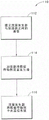
Fig. 13 illustrates an example of a process flow or control routine 210 for displaying or allowing control of the peripheral devices 182, 190, 202, or allowing the humidifier 20 to run based on data of the system 180 of fig. 11 or the system 200 of fig. 12. At block 212, communication is established between the humidifier 20 and the peripheral devices 182, 190, 202 using any suitable method or scheme, such as those described above. At block 214, the peripherals 182, 190, 202 transmit data to the humidifier 20, which may include any pertinent information regarding the operation of the peripherals 182, 190, 202. At block 216, the humidifier 20 displays some or all of the peripheral data on the user interface 186 of the humidifier 20, as appropriate. At block 218, the humidifier 20 may set or confirm the operating parameters or operating mode based on the peripheral data, where appropriate. For example, if the peripheral device is the nebulizer 182, the nebulizer data may include an alarm condition (e.g., overheating of the nebulizer) and in response, the humidifier 20 may take appropriate action (e.g., turn off the heating element). In addition, the user interface 186 of the humidifier 20 may be utilized to set parameters of the peripherals 182, 190, 202.
In some of the systems disclosed herein, the flow generator is described as a ventilator for purposes of example. However, these systems may include any type of ventilator or any other type of flow generator capable of delivering a flow of breathing gas. For example, the flow generator may be a Continuous Positive Airway Pressure (CPAP) machine, a variable or bi-level positive airway pressure (VPAP or BPAP) machine, an infant ventilator, or a machine capable of operating in one or more of these modes. The flow generator may also be, for example, an electronic gas mixer, bottled gas, or gas from a wall source. Thus, the term ventilator is used herein by way of example and not limitation.
Although the present invention has been disclosed in the context of certain preferred embodiments and examples, it will be understood by those skilled in the art that the present invention extends beyond the specifically disclosed embodiments to other alternative embodiments and/or uses of the invention and obvious modifications and equivalents thereof. In particular, while the systems of the present invention have been described in the context of particularly preferred embodiments, those skilled in the art will appreciate, in view of the present disclosure, that certain advantages, features, and aspects of the systems may be realized in a variety of other applications, many of which have been noted above. In addition, it is contemplated that the various aspects and features of the invention described may be implemented separately, combined together, or substituted for one another, and that numerous combinations and subcombinations of the features and aspects may be made and still fall within the scope of the invention. Thus, it is intended that the scope of the invention herein disclosed should not be limited by the particular disclosed embodiments described above, but should be determined only by a fair reading of the claims that follow.
Throughout this specification and the claims, the terms "comprises," "comprising," and the like are to be construed in an inclusive sense, i.e., in a sense that "includes but is not limited to," unless the context clearly requires otherwise.
Although the present invention has been described by way of example and with reference to possible embodiments thereof, it should be understood that various changes or modifications can be made therein without departing from the spirit and scope of the invention and without diminishing its attendant advantages. Further, where reference has been made to specific components or integers of the invention having known equivalents, such equivalents are herein incorporated as if individually set forth.
Any discussion of the prior art throughout the specification should in no way be considered as an admission that such prior art is widely known or forms part of the common general knowledge in the field anywhere in the world.