CN107710073B - Inspection apparatus, inspection method, lithographic apparatus, patterning device, and manufacturing method - Google Patents
Inspection apparatus, inspection method, lithographic apparatus, patterning device, and manufacturing method Download PDFInfo
- Publication number
- CN107710073B CN107710073B CN201680034173.2A CN201680034173A CN107710073B CN 107710073 B CN107710073 B CN 107710073B CN 201680034173 A CN201680034173 A CN 201680034173A CN 107710073 B CN107710073 B CN 107710073B
- Authority
- CN
- China
- Prior art keywords
- target
- measurement
- substrate
- targets
- parameter
- Prior art date
- Legal status (The legal status is an assumption and is not a legal conclusion. Google has not performed a legal analysis and makes no representation as to the accuracy of the status listed.)
- Active
Links
Images


Classifications
-
- G—PHYSICS
- G03—PHOTOGRAPHY; CINEMATOGRAPHY; ANALOGOUS TECHNIQUES USING WAVES OTHER THAN OPTICAL WAVES; ELECTROGRAPHY; HOLOGRAPHY
- G03F—PHOTOMECHANICAL PRODUCTION OF TEXTURED OR PATTERNED SURFACES, e.g. FOR PRINTING, FOR PROCESSING OF SEMICONDUCTOR DEVICES; MATERIALS THEREFOR; ORIGINALS THEREFOR; APPARATUS SPECIALLY ADAPTED THEREFOR
- G03F7/00—Photomechanical, e.g. photolithographic, production of textured or patterned surfaces, e.g. printing surfaces; Materials therefor, e.g. comprising photoresists; Apparatus specially adapted therefor
- G03F7/70—Microphotolithographic exposure; Apparatus therefor
- G03F7/70483—Information management; Active and passive control; Testing; Wafer monitoring, e.g. pattern monitoring
- G03F7/70605—Workpiece metrology
- G03F7/70616—Monitoring the printed patterns
- G03F7/70641—Focus
-
- G—PHYSICS
- G03—PHOTOGRAPHY; CINEMATOGRAPHY; ANALOGOUS TECHNIQUES USING WAVES OTHER THAN OPTICAL WAVES; ELECTROGRAPHY; HOLOGRAPHY
- G03F—PHOTOMECHANICAL PRODUCTION OF TEXTURED OR PATTERNED SURFACES, e.g. FOR PRINTING, FOR PROCESSING OF SEMICONDUCTOR DEVICES; MATERIALS THEREFOR; ORIGINALS THEREFOR; APPARATUS SPECIALLY ADAPTED THEREFOR
- G03F1/00—Originals for photomechanical production of textured or patterned surfaces, e.g., masks, photo-masks, reticles; Mask blanks or pellicles therefor; Containers specially adapted therefor; Preparation thereof
- G03F1/38—Masks having auxiliary features, e.g. special coatings or marks for alignment or testing; Preparation thereof
- G03F1/44—Testing or measuring features, e.g. grid patterns, focus monitors, sawtooth scales or notched scales
-
- G—PHYSICS
- G03—PHOTOGRAPHY; CINEMATOGRAPHY; ANALOGOUS TECHNIQUES USING WAVES OTHER THAN OPTICAL WAVES; ELECTROGRAPHY; HOLOGRAPHY
- G03F—PHOTOMECHANICAL PRODUCTION OF TEXTURED OR PATTERNED SURFACES, e.g. FOR PRINTING, FOR PROCESSING OF SEMICONDUCTOR DEVICES; MATERIALS THEREFOR; ORIGINALS THEREFOR; APPARATUS SPECIALLY ADAPTED THEREFOR
- G03F7/00—Photomechanical, e.g. photolithographic, production of textured or patterned surfaces, e.g. printing surfaces; Materials therefor, e.g. comprising photoresists; Apparatus specially adapted therefor
- G03F7/70—Microphotolithographic exposure; Apparatus therefor
- G03F7/70483—Information management; Active and passive control; Testing; Wafer monitoring, e.g. pattern monitoring
- G03F7/70491—Information management, e.g. software; Active and passive control, e.g. details of controlling exposure processes or exposure tool monitoring processes
- G03F7/70516—Calibration of components of the microlithographic apparatus, e.g. light sources, addressable masks or detectors
-
- G—PHYSICS
- G03—PHOTOGRAPHY; CINEMATOGRAPHY; ANALOGOUS TECHNIQUES USING WAVES OTHER THAN OPTICAL WAVES; ELECTROGRAPHY; HOLOGRAPHY
- G03F—PHOTOMECHANICAL PRODUCTION OF TEXTURED OR PATTERNED SURFACES, e.g. FOR PRINTING, FOR PROCESSING OF SEMICONDUCTOR DEVICES; MATERIALS THEREFOR; ORIGINALS THEREFOR; APPARATUS SPECIALLY ADAPTED THEREFOR
- G03F7/00—Photomechanical, e.g. photolithographic, production of textured or patterned surfaces, e.g. printing surfaces; Materials therefor, e.g. comprising photoresists; Apparatus specially adapted therefor
- G03F7/70—Microphotolithographic exposure; Apparatus therefor
- G03F7/70483—Information management; Active and passive control; Testing; Wafer monitoring, e.g. pattern monitoring
- G03F7/70491—Information management, e.g. software; Active and passive control, e.g. details of controlling exposure processes or exposure tool monitoring processes
- G03F7/70525—Controlling normal operating mode, e.g. matching different apparatus, remote control or prediction of failure
-
- G—PHYSICS
- G03—PHOTOGRAPHY; CINEMATOGRAPHY; ANALOGOUS TECHNIQUES USING WAVES OTHER THAN OPTICAL WAVES; ELECTROGRAPHY; HOLOGRAPHY
- G03F—PHOTOMECHANICAL PRODUCTION OF TEXTURED OR PATTERNED SURFACES, e.g. FOR PRINTING, FOR PROCESSING OF SEMICONDUCTOR DEVICES; MATERIALS THEREFOR; ORIGINALS THEREFOR; APPARATUS SPECIALLY ADAPTED THEREFOR
- G03F7/00—Photomechanical, e.g. photolithographic, production of textured or patterned surfaces, e.g. printing surfaces; Materials therefor, e.g. comprising photoresists; Apparatus specially adapted therefor
- G03F7/70—Microphotolithographic exposure; Apparatus therefor
- G03F7/70483—Information management; Active and passive control; Testing; Wafer monitoring, e.g. pattern monitoring
- G03F7/7055—Exposure light control in all parts of the microlithographic apparatus, e.g. pulse length control or light interruption
- G03F7/70558—Dose control, i.e. achievement of a desired dose
-
- G—PHYSICS
- G03—PHOTOGRAPHY; CINEMATOGRAPHY; ANALOGOUS TECHNIQUES USING WAVES OTHER THAN OPTICAL WAVES; ELECTROGRAPHY; HOLOGRAPHY
- G03F—PHOTOMECHANICAL PRODUCTION OF TEXTURED OR PATTERNED SURFACES, e.g. FOR PRINTING, FOR PROCESSING OF SEMICONDUCTOR DEVICES; MATERIALS THEREFOR; ORIGINALS THEREFOR; APPARATUS SPECIALLY ADAPTED THEREFOR
- G03F7/00—Photomechanical, e.g. photolithographic, production of textured or patterned surfaces, e.g. printing surfaces; Materials therefor, e.g. comprising photoresists; Apparatus specially adapted therefor
- G03F7/70—Microphotolithographic exposure; Apparatus therefor
- G03F7/70483—Information management; Active and passive control; Testing; Wafer monitoring, e.g. pattern monitoring
- G03F7/70605—Workpiece metrology
- G03F7/70616—Monitoring the printed patterns
- G03F7/70625—Dimensions, e.g. line width, critical dimension [CD], profile, sidewall angle or edge roughness
-
- G—PHYSICS
- G03—PHOTOGRAPHY; CINEMATOGRAPHY; ANALOGOUS TECHNIQUES USING WAVES OTHER THAN OPTICAL WAVES; ELECTROGRAPHY; HOLOGRAPHY
- G03F—PHOTOMECHANICAL PRODUCTION OF TEXTURED OR PATTERNED SURFACES, e.g. FOR PRINTING, FOR PROCESSING OF SEMICONDUCTOR DEVICES; MATERIALS THEREFOR; ORIGINALS THEREFOR; APPARATUS SPECIALLY ADAPTED THEREFOR
- G03F7/00—Photomechanical, e.g. photolithographic, production of textured or patterned surfaces, e.g. printing surfaces; Materials therefor, e.g. comprising photoresists; Apparatus specially adapted therefor
- G03F7/70—Microphotolithographic exposure; Apparatus therefor
- G03F7/70483—Information management; Active and passive control; Testing; Wafer monitoring, e.g. pattern monitoring
- G03F7/70605—Workpiece metrology
- G03F7/706843—Metrology apparatus
- G03F7/706845—Calibration, e.g. tool-to-tool calibration, beam alignment, spot position or focus
Landscapes
- Physics & Mathematics (AREA)
- General Physics & Mathematics (AREA)
- Exposure And Positioning Against Photoresist Photosensitive Materials (AREA)
- Testing Or Measuring Of Semiconductors Or The Like (AREA)
- Thermistors And Varistors (AREA)
- Analysing Materials By The Use Of Radiation (AREA)
- Length Measuring Devices By Optical Means (AREA)
Abstract
公开了一种在光刻工艺期间监测焦距参数的方法。该方法包括分别获取第一目标和第二目标的第一测量值和第二测量值,其中第一目标和第二目标已经以相对最佳焦距偏移被曝光。该方法然后包括根据第一测量值和第二测量值确定焦距参数。还公开了相应的测量和光刻设备、计算机程序和制造器件的方法。

A method of monitoring a focus parameter during a lithography process is disclosed. The method includes acquiring first and second measurements of a first object and a second object, respectively, wherein the first object and the second object have been exposed at relative optimum focus offsets. The method then includes determining a focus parameter from the first measurement and the second measurement. Corresponding metrology and lithographic apparatus, computer programs and methods of fabricating devices are also disclosed.
Description
Cross Reference to Related Applications
This application claims priority to EP application 15171970.5 filed on 12/6/2015, the entire contents of which are incorporated herein by reference.
Technical Field
The present invention relates to inspection apparatus and methods that may be used to perform metrology in the manufacture of devices, for example by lithographic techniques. The invention also relates to such a method for monitoring focus and/or dose parameters in a lithographic process.
Background
A lithographic apparatus is a machine that applies a desired pattern onto a substrate, usually onto a target portion of the substrate. Lithographic apparatus can be used, for example, in the manufacture of Integrated Circuits (ICs). In such cases, a patterning device, which is alternatively referred to as a mask or a reticle, may be used to generate a circuit pattern to be formed on an individual layer of the IC. The pattern can be transferred onto a target portion (e.g., a portion including one or more dies) on a substrate (e.g., a silicon wafer). The transfer of the pattern is typically via imaging onto a layer of radiation-sensitive material (resist) provided on the substrate. Typically, a single substrate will contain a network of adjacent target portions that are successively patterned.
In lithographic processes, it is often desirable to perform measurements on the created structures, for example for process control and verification. Various tools for making such measurements are known, including scanning electron microscopes, which are often used to measure Critical Dimensions (CD), and specialized tools for measuring overlay (i.e., the accuracy of the alignment of two layers in a device). Recently, various forms of scatterometers have been developed for use in the field of lithography. These devices direct a beam of radiation onto a target and measure one or more properties of the scattered radiation, such as the intensity at a single angle of reflection as a function of wavelength; intensity at one or more wavelengths as a function of reflection angle; or polarization as a function of the angle of reflection, to obtain a diffraction "spectrum" from which a property of interest of the target can be determined.
Examples of known scatterometers include angle-resolved scatterometers of the type described in US2006033921a1 and US2010201963a 1. Such scatterometers use a relatively large (e.g., 40 μm by 40 μm) grating of the target and the measurement beam generates a spot that is smaller than the grating (i.e., the grating is not filled). Examples of dark-field imaging metrics can be found in international patent applications US20100328655a1 and US2011069292a1, the entire contents of which are incorporated herein by reference. Further developments in the technology have been described in published patent publications US20110027704A, US20110043791A, US2011102753a1, US20120044470A, US20120123581A, US20130258310A, US20130271740A and WO2013178422a 1. These targets may be smaller than the illumination spot and may be surrounded by product structures on the wafer. Multiple gratings may be measured in one image using a composite grating target. The contents of all of these applications are also incorporated herein by reference.
One important parameter of the lithographic process that needs to be monitored is the focal length. More and more electronic components need to be integrated into an IC. To achieve this, it is necessary to reduce the size of the components and, therefore, increase the resolution of the projection system so that smaller and smaller details or line widths can be projected onto a target portion of the substrate. As the Critical Dimension (CD) in lithography shrinks, focus uniformity (whether on or between substrates) becomes increasingly important. CD is the dimension of a feature, such as the gate width of a transistor, whose variation will result in an undesirable variation in the physical characteristics of the feature. Traditionally, the optimal settings are determined by "pre-sending wafers" (i.e., substrates that are exposed, developed, and measured prior to a production run). In the pre-launch wafer, the test structures are exposed in a so-called focal distance energy matrix (FEM), and the optimal focal distance and energy settings are determined by inspecting these test structures.
Current test structure designs and key measurement methods have a number of disadvantages. Many test structures require sub-resolution features or grating structures with large pitches. Such a structure may violate design rules of a user of the lithographic apparatus. The focus measurement technique may include measuring an asymmetry in the relatively higher (e.g., first) order radiation scattered by a particular, focus-related target structure, and determining the focus based on the asymmetry. For EUV lithography, the resist thickness, and thus the thickness of the target structure, is smaller (e.g., half as thick). Therefore, focus sensitivity and signal strength may not be sufficient to use such asymmetric methods in EUV lithography. Furthermore, techniques based on asymmetries may require careful selection of the target geometry to ensure the desired relationship (e.g., linearity) between asymmetry and focal length. This selection process can be complex and requires a great deal of effort to find a suitable target geometry. Even a suitable target geometry may not exist.
Disclosure of Invention
The present invention is directed to addressing one or more of the above-identified deficiencies.
A first aspect of the invention provides a method of monitoring a focus parameter during a lithographic process, the method comprising:
obtaining a first measurement value, said first measurement value having been obtained from an inspection of a first target;
obtaining a second measurement value, said second measurement value having been obtained from an inspection of a second object,
wherein the first target and the second target have been exposed with a relative best focus offset;
determining a focal length parameter from the first and second measurements.
The invention also provides a method of manufacturing a device in which a device pattern is applied to a series of substrates using a lithographic process, the method comprising:
-monitoring the focus parameter using the method of the first aspect, and
controlling the lithography process of the subsequent substrate according to the determined focus parameter.
The invention still further provides a computer program product comprising machine readable instructions for causing a processor to perform the method of the first aspect.
The invention also provides a patterning device configured to pattern a beam of radiation in a lithographic process according to a desired pattern, the patterning device comprising a first feature for forming a first target on a substrate during the lithographic process and a second feature for forming a second target on the substrate during the lithographic process; wherein the second feature is higher than the first feature in a direction transverse to a plane of the target and such that the first target and the second target have a relative best focus offset.
The invention also provides a method of monitoring a dose parameter during a lithographic process, the method comprising: obtaining a first measurement value, the first measurement value having been obtained from an inspection of a first target; obtaining a second measurement value, the second measurement value having been obtained from an examination of a second target, determining a dosage parameter from the first measurement value and the second measurement value; wherein the first target and the second target comprise respective line and space targets having the same pitch and inverse duty cycle.
The present invention still further provides a method of manufacturing a device in which a device pattern is applied to a series of substrates using a lithographic process, the method comprising: the method of the immediately above aspect is used to monitor the dose parameter and control the lithographic process for a subsequent substrate in accordance with the determined dose parameter.
The present invention also provides a patterning device configured to pattern a beam of radiation in a lithographic process according to a desired pattern, the patterning device comprising a first feature for forming a first target on a substrate during the lithographic process and a second feature for forming a second target on the substrate during the lithographic process; wherein the first feature is configured to form the first target with line features having substantially focus independent sidewall angles and the second feature is configured to form the second target with line features having focus dependent sidewall angles.
The invention also provides a patterning device configured to pattern a beam of radiation in a lithographic process according to a desired pattern, the patterning device comprising a first feature for forming a first target on a substrate during the lithographic process and a second feature for forming a second target on the substrate during the lithographic process; wherein the design rule constrains the target feature to a set critical dimension and on a grid of set pitches, wherein the first target and the second target are each formed by a row of the grid such that each of the first feature and the second feature is formed by one or more adjacent respective target features formed on the grid.
Further features and advantages of the invention, as well as the structure and operation of various embodiments of the invention, are described in detail below with reference to the accompanying drawings. It should be noted that the present invention is not limited to the specific embodiments described herein. These embodiments are presented herein for illustrative purposes only. Other embodiments will be apparent to persons skilled in the relevant art(s) based on the teachings contained herein.
Drawings
Embodiments of the invention will now be described, by way of example only, with reference to the accompanying schematic drawings in which corresponding reference symbols indicate corresponding parts, and in which:
FIG. 1 depicts a lithographic apparatus;
FIG. 2 depicts a lithographic cell or cluster in which an inspection apparatus according to the present invention may be used;
fig. 3 shows the principle of operation of a spectral scatterometer as a first example of an examination apparatus;
fig. 4 shows in schematic form an angle-resolved scatterometer as another example of an examination apparatus;
figure 5 schematically shows an inspection apparatus adapted to perform an angle-resolved scatterometry and dark-field imaging inspection method;
FIG. 6 shows a target-forming element on a reticle suitable for forming a grating on a substrate having a focus-dependent asymmetry;
FIG. 7 shows (a) a plot of measured values of target parameters (y-axis) versus focal length for two targets with a relative best focus offset; (b) a plot of the difference between measured values of a target parameter from a first target and a second target (y-axis) versus focal length (x-axis);
8(a) -8 (d) schematically show possible target formation designs on a reticle in cross-sectional views;
FIG. 9 schematically illustrates, in cross-section, (a) a reticle blank according to an embodiment and (b) another possible target formation design on a reticle;
FIG. 10 schematically illustrates, in plan view, yet another possible target formation design on a reticle;
FIG. 11 is a flow chart of a method of monitoring focus according to an embodiment of the invention;
FIG. 12 schematically illustrates, in plan view, a possible target formation design on a reticle for performing dose measurements;
FIG. 13 shows a plot of measured intensity (y-axis) versus CD (x-axis) of a target such as that shown in FIG. 12; and
14(a) through 14(f) each show examples of possible target feature formation designs when constrained by exemplary grid-based design rules.
Detailed Description
Before describing embodiments of the present invention in detail, it is helpful to present an example environment in which embodiments of the present invention may be implemented.
FIG. 1 schematically depicts a lithographic apparatus LA. The apparatus comprises: an illumination system (illuminator) IL configured to condition a radiation beam B (e.g. UV radiation or DUV radiation); a patterning device support or support structure (e.g. a mask table) MT constructed to support a patterning device (e.g. a mask) MA and connected to a first positioner PM configured to accurately position the patterning device in accordance with certain parameters; two substrate tables (e.g. wafer tables) WTa and WTb, each constructed to hold a substrate (e.g. a resist-coated wafer) W and each connected to a second positioner PW configured to accurately position the substrate in accordance with certain parameters; and a projection system (e.g. a refractive projection lens system) PS configured to project a pattern imparted to the radiation beam B by patterning device MA onto a target portion C (e.g. comprising one or more dies) of the substrate W. The reference frame RF connects the various components and serves as a reference for setting up and measuring the position of the patterning device and the substrate, as well as the features on them.
The illumination system may include various types of optical components, such as refractive, reflective, magnetic, electromagnetic, electrostatic or other types of optical components, or any combination thereof, for directing, shaping, or controlling radiation.
The patterning device support holds the patterning device in a manner that depends on the orientation of the patterning device, the design of the lithographic apparatus, and other conditions, such as for example whether or not the patterning device is held in a vacuum environment. The patterning device support may take a variety of forms. The patterning device support may ensure that the patterning device is at a desired position, for example with respect to the projection system.
The term "patterning device" used herein should be broadly interpreted as referring to any device that can be used to impart a radiation beam with a pattern in its cross-section such as to create a pattern in a target portion of the substrate. It should be noted that the pattern imparted to the radiation beam may not exactly correspond to the desired pattern in the target portion of the substrate, for example where the pattern includes phase-shifting features or so called assist features. Generally, the pattern imparted to the radiation beam will correspond to a particular functional layer in a device being created in the target portion, such as an integrated circuit.
As here depicted, the apparatus is of a transmissive type (e.g., employing a transmissive patterning device). Alternatively, the apparatus may be of a reflective type (e.g. employing a programmable mirror array of a type as referred to above, or employing a reflective mask). Examples of patterning devices include masks, programmable mirror arrays, and programmable LCD panels. Any use of the terms "reticle" or "mask" herein may be considered synonymous with the more general term "patterning device". The term "patterning device" may also be construed to refer to any apparatus that stores pattern information in digital form for use in controlling such a programmable patterning device.
The term "projection system" used herein should be broadly interpreted as encompassing any type of projection system, including refractive, reflective, catadioptric, magnetic, electromagnetic and electrostatic optical systems, or any combination thereof, as appropriate for the exposure radiation being used, or for other factors such as the use of an immersion liquid or the use of a vacuum. Any use of the term "projection lens" herein may be considered as synonymous with the more general term "projection system".
The lithographic apparatus may also be of a type wherein at least a portion of the substrate may be covered by a liquid having a relatively high refractive index, e.g., water, so as to fill a space between the projection system and the substrate. Immersion liquids may also be applied to other spaces in the lithographic apparatus, for example, between the mask and the projection system. Immersion techniques for increasing the numerical aperture of projection systems are well known in the art.
In operation, the illuminator IL receives a radiation beam from a radiation source SO. The source and the lithographic apparatus may be separate entities, for example when the source is an excimer laser. In such cases, the source is not considered to form part of the lithographic apparatus and the radiation beam is passed from the source SO to the illuminator IL with the aid of a beam delivery system BD comprising, for example, suitable directing mirrors and/or a beam expander. In other cases the source may be an integral part of the lithographic apparatus, for example when the source is a mercury lamp. The source SO and the illuminator IL, together with the beam delivery system BD if required, may be referred to as a radiation system.
The illuminator IL may, for example, comprise an adjuster AD for adjusting the angular intensity distribution of the radiation beam, an integrator IN, and a condenser CO. The illuminator may be used to condition the radiation beam, to have a desired uniformity and intensity distribution in its cross-section.
The radiation beam B is incident on the patterning device MA, which is held on the patterning device support MT, and is patterned by the patterning device. After passing through the patterning device (e.g. mask) MA, the radiation beam B passes through the projection system PS, which focuses the beam onto a target portion C of the substrate W. With the aid of the second positioner PW and position sensor IF (e.g., an interferometric device, linear encoder, 2-D encoder or capacitive sensor), the substrate table WTa or WTb can be moved accurately, e.g., so as to position different target portions C in the path of the radiation beam B. Similarly, the first positioner PM and another position sensor (which is not explicitly depicted in fig. 1) can be used to accurately position the patterning device (e.g. reticle/mask) MA with respect to the path of the radiation beam B, e.g. after mechanical retrieval from a mask library, or during a scan.
Patterning device (e.g., reticle/mask) MA and substrate W may be aligned using mask alignment marks M1, M2 and substrate alignment marks P1, P2. Although the substrate alignment marks as shown occupy dedicated target portions, they may be located in spaces between target portions (these are known as scribe-lane alignment marks). Similarly, in situations in which more than one die is provided on the patterning device (e.g., mask) MA, the mask alignment marks may be located between the dies. In device features, small alignment marks may also be included within the die, in which case it is desirable that the marks be as small as possible and that different imaging or process conditions from adjacent features are not required. An alignment system for detecting alignment marks is described further below.
The depicted device may be used in various modes. In scan mode, the patterning device support (e.g., mask table) MT and the substrate table WT are scanned simultaneously, while a pattern imparted to the radiation beam is projected onto a target portion C (i.e., a single dynamic exposure). The velocity and direction of the substrate table WT relative to the patterning device support (e.g. mask table) MT may be determined by the (de-) magnification and image reversal characteristics of the projection system PS. In scan mode, the maximum size of the exposure field limits the width (in the non-scanning direction) of the target portion in a single dynamic exposure, whereas the length of the scanning motion determines the height (in the scanning direction) of the target portion. Other types of lithographic apparatus and modes of operation are possible, as are well known in the art. For example, a step mode is known. In so-called "maskless" lithography, the programmable patterning device is held stationary, but with a changing pattern, and the substrate table WT is moved or scanned.
Combinations and/or variations on the above described modes of use or entirely different modes of use may also be employed.
The lithographic apparatus LA is of a so-called dual stage type, having two substrate tables WTa, WTb and two stations, an exposure station EXP and a measurement station MEA, between which the substrate tables can be exchanged. When one substrate on one substrate table is exposed at the exposure station, another substrate may be loaded onto another substrate table at the measurement station and various preparatory steps performed. This results in a significant increase in the throughput of the device. The preliminary steps may include mapping the surface height profile of the substrate using the level sensor LS and measuring the position of the alignment marks on the substrate using the alignment sensor AS. IF the position sensor IF is not able to measure the position of the substrate table when it is at the measurement station and at the exposure station, a second position sensor may be provided to enable the position of the substrate table to be tracked relative to the reference frame RF at both stations. Other configurations are known and may be used in place of the two-stage arrangement shown. For example, other lithographic apparatus are known in which a substrate table and a measurement table are provided. These are docked together when the preparatory measurements are performed and then undocked when the substrate table undergoes exposure.
As shown in fig. 2, the lithographic apparatus LA forms part of a lithographic cell LC, sometimes also referred to as a lithographic cell (lithocell) or cluster, which also includes means for performing pre-exposure and post-exposure processing on the substrate. Conventionally, these include a spin coater SC for depositing a resist layer, a developer DE for developing the exposed resist, a cooling plate CH, and a baking plate BK. The substrate handler or robot RO picks up the substrate from the input/output ports I/O1, I/O2, moves the substrate between different processing apparatuses, and then delivers it to the loading station LB of the lithographic apparatus. These devices, which are generally referred to collectively as the track, are under the control of a track control unit TCU, which is itself controlled by a supervisory control system SCS, which also controls the lithographic apparatus via the lithographic control unit LACU. Thus, different equipment may be operated to maximize throughput and processing efficiency.
In order to properly and consistently expose a substrate exposed by a lithographic apparatus, it is desirable to inspect the exposed substrate to measure various properties, such as overlay error between subsequent layers, line thickness, Critical Dimension (CD), and the like. Thus, the manufacturing apparatus in which the lithography unit LC is located also comprises a metrology system MET which receives some or all of the substrates W that have been processed in the lithography unit. The measurement results are directly or indirectly provided to the supervisory control system SCS. If an error is detected, adjustments can be made to the exposure of subsequent substrates, particularly if the inspection can be made quickly and quickly enough so that other substrates of the same lot are still exposed. Moreover, the already exposed substrates may be stripped and reworked to improve yield or discarded, thereby avoiding further processing of known defective substrates. In the event that only some target portions of the substrate fail, further exposures may be made only to those good target portions.
Within the metrology system MET, inspection equipment is used to determine properties of substrates, and in particular how properties of different substrates or different layers of the same substrate vary from layer to layer. The inspection device may be integrated into the lithographic apparatus LA or the lithographic cell LC or may be a stand-alone device. To enable the fastest measurements, it is desirable for the inspection apparatus to measure the properties in the exposed resist layer immediately after exposure. However, the latent image in the resist has very low contrast (the difference in refractive index between the portions of the resist exposed to radiation and those not exposed to radiation is very small) and not all inspection devices have sufficient sensitivity to make a useful measurement of the latent image. Thus, the measurements may be performed after a post-exposure bake step (PEB), which is typically the first step performed on the exposed substrate and increases the contrast between the exposed and unexposed portions of the resist. At this stage, the image in the resist may be referred to as a semi-latent image. Measurements may also be taken on developed resist images (at which point either the exposed or unexposed portions of the resist have been removed), or after a pattern transfer step such as etching. The latter possibility limits the possibility of rework of faulty substrates but may still provide useful information.
Fig. 3 depicts a known spectral scatterometer which can be used as an inspection device in a metrology system of the type described above. It comprises a broadband (white light) radiation projector 2 which projects radiation onto a substrate W. The reflected radiation is transmitted to a spectrometer 4, which spectrometer 4 measures the spectrum 6 (intensity as a function of wavelength) of the specularly reflected radiation. From this data, the structure or distribution 8 that caused the detected spectrum can be reconstructed by calculations within the processing unit PU. The reconstruction may be performed by, for example, rigorous coupled wave analysis and non-linear regression, or compared to a library of pre-measured spectra or pre-calculated simulated spectra. In general, for reconstruction, the general form of the structure is known and some parameters are assumed from knowledge of the process of making the structure, so that only some parameters of the structure need to be determined from scatterometry data. Such scatterometers may be configured as normal incidence scatterometers or oblique incidence scatterometers.
Fig. 4 shows the basic elements of a known angularly resolved scatterometer that can be used instead of or in addition to a spectroscopic scatterometer. In this type of examination apparatus, the radiation emitted by the radiation source 11 is modulated by the illumination system 12. For example, the illumination system 12 may include a collimating lens system 12a, a color filter 12b, a polarizer 12c, and an aperture device 13. The conditioned radiation follows an illumination path IP in which it is partially reflected by the reflective surface 15 and focused to a point S on the substrate W via the microscope objective 16. A metrology target T may be formed on a substrate W. The lens 16 has a high Numerical Aperture (NA), preferably at least 0.9, and more preferably at least 0.95. Immersion fluids may be used to achieve numerical apertures greater than 1, as desired.
As in the lithographic apparatus LA, one or more substrate tables may be provided to hold the substrate W during measurement operations. The substrate table may be similar or identical in form to the substrate tables WTa, WTb of fig. 1. (in examples where the inspection apparatus is integrated with the lithographic apparatus, they may even be the same substrate table.) the coarse and fine positioners may be configured to accurately position the substrate relative to the measurement optics. Various sensors and actuators are provided, for example, to take the position of the object of interest and place it in a position below the objective lens 16. Typically, many measurements will be made on a target at different locations on the substrate W. The substrate support may be moved in the X and Y directions to obtain different targets and in the Z direction to obtain the desired focus of the optical system on the target. When in practice the optical system remains substantially stationary and only the substrate is moved, it is convenient to consider and describe the operation as if the objective lens and the optical system were brought to different positions on the substrate. If the relative positions of the substrate and the optical system are correct, it is in principle not important whether one or both of them are moving in the real world.
When the radiation beam is incident on the beam splitter 16, part of it passes through the beam splitter and follows the reference path RP towards the reference mirror 14.
Radiation reflected by the substrate (including radiation diffracted by any metrology target T) is collected by the lens 16 and follows a collection path CP in which it partially enters the detector 19 through the reflective surface 15. The detector may be located in the back projected pupil plane P at the focal length F of the lens 16. In practice, the pupil plane itself may be inaccessible and may instead be re-imaged with secondary optics (not shown) onto a detector located in the so-called conjugate pupil plane P'. The detector is preferably a two-dimensional detector so that a two-dimensional angular scattering spectrum or diffraction spectrum of the substrate target 30 can be measured. In the pupil plane or conjugate pupil plane, the radial position of the radiation defines the angle of incidence/departure of the radiation in the plane of the focused spot S, and the angular position about the optical axis O defines the azimuth angle of the radiation. The detector 19 may be an array of CCD or CMOS sensors, for example, and may use an integration time of 40 milliseconds per frame, for example.
The radiation in the reference path RP is projected onto a different part of the same detector 19 or, alternatively, onto a different detector (not shown). The reference beam is typically used, for example, to measure the intensity of incident radiation to allow normalization of the intensity values measured in the scattering spectrum.
The various components of the illumination system 12 may be adjustable to achieve different metrology "recipes" within the same apparatus. The color filter 12b may be implemented, for example, by a set of interference filters to select different wavelengths of interest in the range of, for example, 405-. The interference filter may be tunable rather than comprising a set of different filters. A grating may be used instead of the interference filter. The polarizer 12c may be rotatable or switchable to achieve different polarization states in the radiation spot S. The aperture device 13 may be adjusted to achieve different illumination profiles. The aperture device 13 is located in a plane P "conjugate to the pupil plane P of the objective lens 16 and to the plane of the detector 19. In this way, the illumination profile defined by the aperture device defines the angular distribution of light incident on the substrate that is radiated through different locations on the aperture device 13.
The detector 19 may measure the intensity of scattered light at a single wavelength (or narrow wavelength range), the intensity at multiple wavelengths respectively, or the intensity integrated over a range of wavelengths. Furthermore, the detector may measure the intensity of the transverse magnetic polarized light and the transverse electric polarized light and/or the phase difference between the transverse magnetic polarized light and the transverse electric polarized light, respectively.
When the metrology target T is provided on the substrate W, it may be a one-dimensional grating, which is printed such that after development, the individual bars are formed from solid photoresist lines. The target may be a two-dimensional grating that is printed such that after development, the grating is formed by solid resist pillars or holes in the resist. Alternatively, the strips, posts or holes may be etched into the substrate. The pattern is sensitive to chromatic aberrations in the lithographic projection apparatus, in particular the projection system PS. The illumination symmetry and the presence of such aberrations will be manifested in the variation of the printed grating. Thus, the scatterometry data of the printed grating is used to reconstruct the grating. Parameters of a one-dimensional grating, such as line width and shape, or parameters of a two-dimensional grating, such as column or hole width or length or shape, may be input to a reconstruction process, which is performed by the processing unit PU based on knowledge of the printing step and/or other scatterometry processes.
In addition to measuring parameters by reconstruction, angle-resolved scatterometry can also be used to measure asymmetry of features in the product and/or resist pattern. A particular application of asymmetry measurement is for measuring focus parameters (e.g., focus setting during exposure of a target) from a target printed with a focus-related asymmetry. The concept of asymmetry measurement using the instrument of fig. 3 or fig. 4 is described, for example, in the above-cited published patent application US2006066855a 1. In short, although the position of the diffraction order in the diffraction spectrum of the target is determined only by the periodicity of the target, the asymmetry of the intensity level in the diffraction spectrum represents the asymmetry in the individual features that make up the target. In the instrument of fig. 4, where the detector 19 may be an image sensor, such asymmetry in the diffraction orders is directly manifested as asymmetry in the pupil image recorded by the detector 19. This asymmetry can be measured by digital image processing in unit PU and from this the focal distance can be determined.
Fig. 5(a) shows in more detail an examination apparatus implementing angle-resolved scatterometry by the same principle as the apparatus of fig. 4, with an additional adaptation for performing so-called dark-field imaging. The apparatus may be a stand-alone apparatus or incorporated into the lithographic apparatus LA, for example at a metrology station, or at the lithographic cell LC. The optical axis with multiple branches in the whole device is indicated by the dashed line O. The target grating T and diffracted radiation are shown in more detail in fig. 5 (b).
The same reference numerals are used for components already described in the apparatus of fig. 4. The illumination path is labeled as before as IP. For clarity, the reference path RP is omitted. In contrast to this device, the second beam splitter 17 splits the collection path into two branches. In the first measurement branch, the detector 19 accurately records the scatter or diffraction spectrum of the target as described above. This detector 19 may be referred to as a pupil image detector.
In the second measurement branch, the imaging optical system 22 forms an image of the target on the substrate W on a sensor 23 (e.g. a CCD or CMOS sensor). An aperture stop 21 (which may also be referred to as a pupil stop) is provided in a plane in the collection path in a plane conjugate to the pupil plane. The aperture stop 21 may take different forms just as the illumination aperture may take different forms. Typically, the aperture stop 21 is used to block the zero order diffracted beam so that the target image formed on the sensor 23 is formed by only the first order beam. This is a so-called dark-field image, corresponding to a dark-field microscope. The images captured by the sensors 19 and 23 are output to an image processor and controller PU, the function of which depends on the particular type of measurement being performed.
In the illumination path in this example, additional optics are shown, so that the field stop 13' can be placed in a plane conjugate to the plane of the target and the image sensor 23. This plane may be referred to as the field plane, or conjugate image plane, and has the following characteristics: each spatial position on the field plane corresponds to a position on the target. The field stop may be used, for example, to shape the illumination point for a particular purpose, or merely to avoid illuminating features that are located within the field of view of the device and not part of the object of interest. By way of example, the following figures and discussion refer to techniques for implementing the functionality of the aperture device 13, but the present disclosure also includes implementing the functionality of the field stop 13' using the same techniques.
As shown in more detail in fig. 5(b), the target grating T is positioned perpendicular to the optical axis O of the objective lens 16 together with the substrate W. In the case of an off-axis illumination profile, the illumination ray I impinging on the grating T from an angle away from the axis O generates a zero-order ray (solid line 0) and two first-order rays (dash-dot line +1 and dash-dot line-1). It should be remembered that for small target gratings that are overfilled, these rays are only one of many parallel rays that cover the area of the substrate that includes the metrology target grating T and other features. Since the apertures in the plate 13 have a finite width (necessary to allow a useful amount of light), the incident radiation I will actually occupy a range of angles, and the diffracted radiation 0 and +1/-1 will expand slightly. According to the point spread function of a small target, each order +1 and-1 will be further distributed over an angular range, rather than a single ideal ray as shown.
Different illumination modes can be achieved by using different apertures. Apertures 13N ("north") and 13S ("south") each provide off-axis illumination only from a particular narrow range of angles. Returning to fig. 5(a), this is illustrated by designating diametrically opposed portions of the annular aperture as north (N) and south (S). The +1 diffracted rays from the north portion of the illuminated cone, labeled +1(13N), enter the objective lens 16, as do the-1 diffracted rays from the south portion of the cone, labeled-1 (13S). As described in the earlier application mentioned in the introduction, the use of the dark field imaging sensor 23 when switching between this type of apertures 13N, 13S is one way to obtain asymmetric measurements from a plurality of small objects. When off-axis illumination is used, the aperture stop 21a may be used to block zero order radiation.
Although off-axis illumination is shown, on-axis illumination of the target may alternatively be used, and an aperture stop with an off-axis aperture may be used to pass substantially only one first order diffracted light to the sensor. In one example, a prism 21b is used instead of the aperture stop 21, the aperture stop 21 having the effect of shifting the +1 and-1 orders to different positions on the sensor 23 so that they can be detected and compared without forming two images. This technique is disclosed in the above-mentioned published patent application US2011102753a1, the contents of which are incorporated herein by reference. Instead of or in addition to the first order beam, second, third and higher order beams (not shown in fig. 5) may be used in the measurement.
In monitoring a lithographic process, it is desirable to monitor the focus of the lithographic beam on the substrate. One known method of determining the focus setting from the printed structure is to measure the Critical Dimension (CD) of the printed structure. CD is a measure of the smallest feature (e.g., line width of a component). The printed structure may be a target formed specifically for focus monitoring, such as a line-space grating. It is known that CDs generally show a second order response to focal length to form a so-called "Bossung curve" on a plot of CD (y-axis) against focal length (x-axis). The Bossung curve is a substantially symmetric curve that is substantially symmetric around a peak representing the best focus. The Bossung curve may be substantially parabolic in shape. This approach has several disadvantages. One disadvantage is that this method shows a low sensitivity (due to the parabolic shape of the curve) near the optimal focal length. Another disadvantage is that this method is insensitive to any out-of-focus sign (since the curve is approximately symmetric around the best focus). Furthermore, the method is particularly sensitive to dose and process variations (cross-talk).
To solve these problems, a diffraction-based focal length (DBF) is designed. Diffraction-based focus can form features using a target on a reticle that prints the target with a degree of asymmetry that depends on the focus setting during printing. This degree of asymmetry can then be measured using scatterometry-based inspection methods, for example by measuring the intensity asymmetry between the intensities of +1 and-1 order radiation diffracted from the target to obtain a measure of the focus setting.
Fig. 6 shows a DBF target formation design 615 configured for diffraction-based focus measurement. It comprises a plurality of DBF structures 620, each DBF structure 620 comprising a high resolution sub-structure 625. The high resolution sub-structure 625 above the base pitch produces an asymmetric resist profile for each DBF structure 620, where the degree of asymmetry depends on the focal length. Thus, the metrology tool can measure the degree of asymmetry from the targets formed using the DBF target formation design 615 and translate it into a scanner focal length.
Although the DBF target formation design 615 enables diffraction-based focus measurements, it is not applicable in all cases. EUV resist film thicknesses are significantly lower than those used in immersion lithography, which makes it difficult to extract accurate asymmetry information from the asymmetric profile of the structure of the portion forming the target. In addition, such structures may not meet the stringent design constraints applicable to certain product structures. During the chip manufacturing process, all features on the reticle must be printed and subjected to subsequent processing steps. Semiconductor manufacturers use design rules as a means of limiting feature design to ensure that printed features meet their process requirements. Examples of such design rules relate to the allowable dimensions of the structures or pitches. Another example design rule relates to pattern density, which may limit the density of the resulting resist pattern to a particular range.
It is therefore proposed to monitor the focus using at least a first and a second target which have formed an optimal focus offset df between the two targets. As previously described, the focus response with the measured value for the target parameter (e.g., CD or other measured value as will be described below) takes the form of a Bossung curve for each of the first and second targets. The focal length is a function of a first measurement of a target parameter obtained from a measurement of a first target and a second measurement of the target parameter obtained from a measurement of a second target. It is therefore proposed to obtain measured values of the parameters from the first and second targets and a value for the focal length derived from these measured values. A specific example of how to derive the focal length is described below with reference to fig. 7. However, those skilled in the art will recognize that there are many alternative methods that allow the focal length to be extracted from measurements taken from a first target and a second target. Although the following description specifically discusses the use of the difference of two measurements (whether they are intensity values or otherwise), other mathematical operations and methods may be used to extract the focus value. For example, one of the measurements (from one of the first and second targets) may be divided by the other measurement (from the other of the first and second targets).
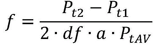
FIG. 7(a) shows the target parameter PtAnd a focal length f of both the first target and the second target. It shows a first Bossung curve 700 corresponding to a first target and a second Bossung curve 710 corresponding to a second target. The best focus offset df (focus offset between the two peaks of the Bossung curves 700, 710) is also shown. Where the target overlay 720 is a focal length range where the difference between the target parameters of the first target and the second target has a substantially linear relationship to the focal length. This is shown in FIG. 7(b), which is such a difference Pt2-Pt1(wherein P ist1Is a target parameter of a first target, Pt2Is the target parameter of the second target) versus focal length. It can be seen that the relationship 740 is linear. Pt2-Pt1The metric may be sensitive to cross-talk, for example, by dose and/or process. The more robust metric may be Pt2-Pt1/PtAVIn which P istAVIs Pt2And Pt1Average value of (a). Also shown in FIG. 7(b) is Pt2-Pt1/PtAVRelation to focal length 750 (dashed line). This relationship is still sufficiently linear while being more robust to crosstalk.
In the particular example shown, the slope of the relationship 740 or the relationship 750 may be described by 2 × df a, where df is the best focus offset and a is the Bossung curvature. Thus, the focal length can be obtained from the following equation (equation 1):
wherein P in the denominatortAVIs optional.
To increase focus sensitivity, the optimum focus offset may be increased, increasing the slope of relationship 740 or relationship 750.
In the discussion above, it should be appreciated that any target parameter P may be usedtAs long as it has a Bossung curve response with the focal length. Although CD can be used, a new diffraction-based focus method is proposed, which has advantages over previous methodsHas significant advantages. The method includes determining a focal distance using intensity signals obtained from diffraction orders of radiation scattered from the first target and the second target. In particular, it is proposed to use intensity values of a single diffraction order from each of the first and second targets to determine the focal distance. The proposed method may use intensity values of respective diffraction orders from the first and second targets. For example, the intensity value may be an intensity value of the +1 (or-1) th diffraction order from the first and second targets. Alternatively or in combination, the intensity value may be an intensity value of the zeroth diffraction order from the first and second targets.
In a specific example of such a method, it is proposed to use the difference dI between the measured intensity of the diffraction order of the radiation scattered by the first target and the measured intensity of the corresponding diffraction order of the radiation scattered by the second target. This difference is hereinafter referred to as the dI metric. However, the dI metric may be any metric derived from the diffracted intensity values from the first and second targets (e.g., by dividing one of the intensity values by the other).
In an embodiment, the dI measure may be the difference in the respective first (or higher) diffraction orders, e.g. the +1 st diffraction order of the radiation scattered by the first target and the +1 st diffraction order of the radiation scattered by the second target (obviously negative orders may be used as well). In another embodiment, the dI metric may include a difference between zeroth order intensity measurements from the first target and the second target.
As previously described, the dI metric may be divided by the average I of the intensity measurementsavTo reduce the effects of crosstalk. However, the Bossung curvature of the dI metric is only weakly dose dependent, so the dI metric may already exhibit sufficiently low dose crosstalk.
Using the dI metric in this manner provides good signal strength and signal-to-noise ratio response even when the target includes a shallow grating (e.g., for use in EUV lithography).
As described above, the dI metric may comprise the difference in zeroth order radiation scattered by the first and second targets. In this way, targets with smaller pitches can be used. Thus, the target pitch of the first target and the second target may be selected to comply with any customer design rule. In addition, a smaller target pitch indicates that the overall target size may be reduced. Multiple pitches are also possible. Using zeroth order radiation means that no diffracted radiation needs to be captured, and the dI metric describes the difference in light absorbed by the target with a relative best focus offset. The zeroth order measurement may also increase signal strength and signal noise characteristics.
In the case of using first order diffracted radiation, and since only a single first order is required for each measurement, the pitch required to use first order radiation light is reduced to λ/2 (where λ is the detection wavelength) within the limits of a numerical aperture NA of 1. Currently this limit is λ. This would mean that the linear target size can be reduced by a factor of 2 and the real estimate by a factor of 4.
The best focus offset between the first target and the second target may be introduced in a number of ways. In one embodiment, a lithographic apparatus for printing a target may have intentionally controlled astigmatism. The astigmatism may be introduced into the projection optics via a plurality of manipulators comprised within the projection optics. Projection lenses in many lithographic apparatus are capable of achieving an astigmatic shift large enough to produce an optimum focus shift without undesirable wavefront effects. In embodiments, astigmatism may introduce an optimal focus offset between horizontal and vertical features. To take advantage of this, the first and second targets may comprise horizontal and vertical gratings, respectively (or vice versa).
In an embodiment, the optimal focus offset may be introduced by a reticle (also referred to as a patterning device or mask). It is proposed to have pairs of targets (e.g. line-spaced gratings) contained on a reticle. The reticle may contain locations of about the target dimension (e.g., 20 x 20 μm, 8 x 8 μm, or 5 x 5 μm) and a boundary region where the substrate is etched to a depth d. One of the first and second target pairs is placed at the normal mask level and the other is placed at the (preferably adjacent) etch position.
Fig. 8 shows a number of alternative reticle arrangements for implementing such an arrangement. Fig. 8a shows in cross-section a reference object that can be used for printing one of the first object and the second object. This is a conventional target feature on a reticle, including a radiation blocking structure 800 on a transparent reticle substrate 810. The reticle may be of any construction or material. For example, the transparent reticle substrate 810 may comprise quartz glass and the radiation blocking structure 800 may comprise chromium, molybdenum silicide (any opacity), or tantalum boron nitride.
This reference target is proposed for use with one of the target arrangements of fig. 8(b), 8(c) or 8 (d). However, any combination of two (or more) of any of the targets shown in FIG. 8 may be used, as long as they result in a relative best focus offset.
Fig. 8(b) shows a transparent reticle substrate 810 that has been etched to a depth d in the target area before the radiation blocking structures 800 are added. Such an arrangement provides a simple goal, but manufacturing is complicated by the inability to do so at a "mask shop". Fig. 8(c) shows an arrangement similar to fig. 8(a), but where the reticle substrate 810 has been etched to a depth d after deposition of the radiation blocking structure 800. Fig. 8(d) shows a structure in which the radiation blocking structure 800 has an additional metal (e.g., chromium) cap 820 on top. This is similar to TIS (transmission image sensor) targets. Such an arrangement is not possible in EUV lithography.
In the example of etching described above, the depth d may be, for example, 0.1 μm or more, more specifically, in the range of 0.1 μm to 5 μm, or 0.5 μm to 5 μm, and, for example, 0.5 μm to 3 μm. In an embodiment, the depth d may be in the region of 1 μm.
FIG. 9 shows another reticle arrangement for achieving an optimal focus offset in a first (reference) target. This arrangement is suitable for (as an example) OMOG (opaque MoSi on glass) and attPSM (attenuated phase shift mask) reticle types. In particular, the trend for attPSM reticles is to reduce Cr thickness. This will reduce the Cr top effect of the fig. 8(d) embodiment described above. Reticle production includes depositing one (or more) additional absorption stacks on the blank; wherein the blank comprises a reticle substrate having a single absorption stack deposited thereon. The absorbing stack may comprise an opaque layer (e.g. a MoSi layer) with a metal layer (e.g. a Cr layer) on top.
Fig. 9(a) shows a new reticle blank. It includes a reticle substrate 910 with two absorbing stacks on top. The first absorption stack includes a first layer 920a (e.g., MoSi layer) and a second layer 920b (e.g., Cr layer). The second absorbent layer also includes two layers: a third layer 920c (e.g., MoSi layer) and a fourth layer 920d (e.g., Cr layer).
Fig. 9(b) shows the final reticle arrangement. It shows a first object 930 and a second object 940. The first target 930 is conventional in that it comprises a single opaque layer (e.g., formed from the first layer of material 920 a) of the barrier structure 900. The second target 940 includes barrier structures 950, each having three layers: a first layer 950a, a second layer 950b and a third layer 950c formed from a first layer of material 920a, a second layer of material 920b and a third layer of material 920c, respectively. The fourth layer 920d is completely removed.
A method of manufacturing such a reticle may comprise the steps of:
depositing one or more additional absorbent laminates on the blank (this may be done by the blank supplier);
etch the target layer (containing targets 930, 940) through both stacks to the depth of the substrate 910.
Remove the additional stack for the first target and its respective layers. This layer contains the product and the reference target (first target), but does not contain the second target. The resist covers the second target in this step;
the reference layer is etched in a conventional manner. The resist covers the second target during this step.
Another method for obtaining two targets with an optimal focus offset between them includes providing: a first target comprising a line separation target having a focus insensitive Side Wall Angle (SWA) such that the SWA of each structure of the first target is focus insensitive; and a SWA second target with focus sensitivity. The second target may comprise a segmentation line, the segmentation being sub-resolution with respect to the lithographic apparatus.
Fig. 10 shows a reticle arrangement for producing such a first target and a second target. A first target 1000 (partially shown) includes a line spacing target having a structure 1010, the structure 1010 producing a corresponding target structure on a substrate having a SWA that is not sensitive to focus. In an embodiment, SWA is small (i.e., near vertical). A second target 1020 (partially shown) comprises a line spacing target having a segmented line structure 1030. The segmented line structure 1030 includes a high resolution sub-structure 1040 that may be similar to the high resolution sub-structure 625 of fig. 6. The second target 1020 is such that the resulting target exposed on the substrate has a focus dependent SWA.
The first target 1000 and the second target 1020 each have a target parameter response with focus that describes a Bossung curve with best focus offset, similar to the response shown in fig. 7. This best focus offset is the result of the focus dependent SWA as only one target. SWA varies linearly with focal length, which results in variation of the Bossung peak. In this way, an asymmetric target (such as the target shown in FIG. 6) can be split into two separate symmetric targets with similar properties. This enables a more efficient target selection and use of the full pitch of the parameter values.
An advantage of introducing an optimal focus offset in the reticle (rather than by astigmatism in the projection optics) is to allow on-product and off-product focus monitoring. The requirement of astigmatism in the projection optics means that this method can only be used for off-product monitoring.
FIG. 11 is a flowchart of steps of a method for monitoring focus parameters during a lithographic process, according to an example embodiment. The steps are as follows, and then described in more detail below:
1100-start.
1110 — printing a first target and a second target with a relative best focus offset;
1120-performing a first measurement to obtain a first measurement value in accordance with an inspection of a first target;
1130 — performing a second measurement to obtain a second measurement value based on the inspection of the second target;
1140-calculating a focal length from a difference between the first measurement and the second measurement;
1150-use of the calculated focus measurement in the focus setting for subsequent exposure.
1160-end.
At step 1110, the first and second targets are printed (at least) at a relative best focus offset, as already described. For example, the relative optimal focus offset may be introduced via a relative depth offset on the reticle between the target forming structures forming the first target and the second target. Alternatively, the relative best focus offset may be introduced via astigmatism in the projection optics of the lithography system. As a further alternative example, the reticle arrangement shown in fig. 10 may be used. Other methods of introducing a relative best focus offset between the two targets are also possible and contemplated within the scope of the present disclosure.
At step 1120, a first measurement is performed to obtain a first measurement value of a parameter of a target in accordance with an inspection of the first target. In an embodiment, the first measurement may be a measurement of the intensity (or a related parameter) of one of the diffraction orders of the radiation scattered by the first target. For example, the first measurement may be obtained using any of the scatterometry devices described herein. It is within the scope of the present disclosure that the first measurement is a CD measurement (whether obtained using a scatterometer, scanning electron microscope, or other suitable device), or any other measurement of a parameter having a Bossung curve relationship to focal length.
At step 1130, a second measurement is performed to obtain a second measurement of the parameter of interest based on the inspection of the second object. This second measurement should be made using the same method as the first measurement. In case the first measurement is a measurement of the intensity (or a related parameter) of one of the diffraction orders of the radiation scattered by the first target, the second measurement should have a measurement of the same diffraction order as the radiation scattered by the second target. The diffraction order may be either the first diffraction order or the zeroth diffraction order. However, higher diffraction orders may also be used and are within the scope of the present disclosure. If more than two targets are printed, further measurements can be taken. These additional targets may each include a different optimal focus offset than the first target and/or the second target.
It should be appreciated that steps 1120 and 1130 may be performed as a single step, such that the first and second measurements are obtained in a single acquisition. In addition, where more than two targets are measured, all targets may be measured in a single acquisition to obtain a corresponding number of measurements. In a specific example, a measurement device such as that shown in fig. 5 may be used to measure a composite target comprising a plurality of individual targets (individual periodic structures or gratings). The gratings of the composite target may be placed close together so that they all lie within the image field or measurement point formed by the illumination beam of the metrology device. In this way, the gratings may all be illuminated simultaneously and imaged simultaneously on the detector. These images can then be processed to identify individual images of the gratings. This can be done by pattern matching techniques so that the images do not have to be aligned very accurately at specific locations within the sensor frame. Once the individual images of the raster have been identified, the intensity of those individual images can be measured, for example, by averaging or summing selected pixel intensity values within the identified region. In another embodiment, the first target and the second target may be included within a composite target, but measured separately in two separate acquisitions.
At step 1140, a focal length is calculated based on the first and second measurements (e.g., based on a difference between the first and second measurements). This calculation may be performed using equation 1 or other suitable equations or methods.
At step 1150, the calculated focus distance may then be used in focus parameter monitoring during subsequent lithography processes in order to maintain focus distance accuracy and consistency during exposure.
The above discussion describes a method for determining focal length. However, methods for measuring dosage are also disclosed. The dose metric based on current diffraction is based on a simulation of the diffraction pattern of a parametric resist pattern. The parameters are then adjusted such that the resulting zeroth order diffraction efficiency, in particular its angular dependence, is consistent with the measurement results. Line/space (LS) targets with CD and pitch in the range of interest are used. This method is called CD reconstruction (CDR) and depends on the correctness of the parameterized model. The model must be a schematic approximation of the resist pattern with a limited number of parameters. The model requires knowledge of the stack's geometric and optical parameters. This is often proprietary information and is therefore difficult to obtain and may be inaccurate.
Thus, a simpler method for determining dose is proposed, which comprises forming a first and a second line spacing target of a resist pattern with an inverted duty cycle, or of a pair of resist patterns with matching properties, such that offset and scaling can be minimized. In an embodiment, the first and second targets each have the same pitch, but in the case where the first target is a line target, the second target will be a corresponding pitch target, such that the line width of the first target is equal to the pitch width of the second target. Fig. 12 shows such a target arrangement with a first target 1200 and a second target 1220, the individual resist features 1210 of the first target 1200 having CD a and the individual resist features 1230 of the second target 1220 having CD b, each target having the same pitch.
FIG. 13 shows a plot 1310 of resist (line) CD versus first order intensity I for a line spacing target with a pitch of 600 nm. It can be seen that the measured intensities of the corresponding line and space targets (e.g., a first target with a resist CD of 150nm and a second target with a resist CD of 450 nm) should be approximately the same. However, the resist CD is dose dependent, such that an increase in dose results in a decrease in resist CD and vice versa. Thus, an increase in dose (for example) will result in a decrease in resist CD for both the first target and the second target. This will result in a decrease in the first order intensity of the first target and an increase in the first order intensity of the second target. It can thus be seen that the dose sensitivity of the first target and the second target are opposite. Thus, the difference in intensity measurements of the first and second targets may be a target parameter used as a dose metric.
It is noted that any process variation to some extent may have the same effect as a dose variation. Process variations such as post-exposure bake (PEB) and Secondary Electron Blur (SEB) variations, as well as bottom anti-reflective coating (BARC) and resist thickness variations, change the exposure intensity in the thin resist film. However, BARC and resist thickness variations affect the measured diffraction intensity: thicker BARCs and resists resulted in an increase in the measured first order strength. This effect is independent of CD and the resulting intensity variation is equal for both targets. If the targets have matching nominal first order strength responses, any crosstalk induced signal offsets will be cancelled out when the measured difference from the two targets is obtained. Any crosstalk induced scaling will be equal for signal differences and signal averages. Thus, it is expected that the ratio of the difference and average measured intensity will be robust to process cross-talk, but sensitive to dose, including process-induced dose effects.
It is recommended that the dose calibration curve be measured as a function of focal length. Assuming that the focal distance is known, the actual dose can be inferred from dose calibration. The focal length may be determined by an earlier diffraction-based focal length method (e.g., using a structure of the form shown in fig. 6) or any other suitable method using any of the methods disclosed herein.
Although the first target and the second target are described as line spacing targets, they may comprise any dose-dependent resist target that produces a suitable first order response. In an embodiment, a correction may be determined to account for any differences corresponding to process-induced dose effects between the target and the product.
The proposed method makes it possible to determine the dose using first order intensity measurements without the need for model simulation or prediction. The method suppresses sensitivity to process variations of the target performance. The irradiation and dose conditions have little effect on the target properties. This method is sensitive to scanning doses and dose-like process effects. The use of first order signals is more accurate than the use of zeroth order signals because they have better shot noise performance.
The targets are described above as line-to-line grating targets because these targets are easily generated and measured. However, the target may include any structure that results in a Bossung curve response between the measurable target parameter and the focal distance. For example, the target may comprise a combination of horizontally and vertically spaced gratings to form a "contact hole" arrangement. Such targets may enable more diffraction orders to be captured. The target arrangement may comprise more than two targets. Thus, the methods described herein may include performing measurements on more than two targets.
In some cases, design rules are imposed that result in constraints on certain parameters of reticle features. An example of such a design rule is to provide a design grid with (and thus imposed on) a fixed pitch and/or CD for the line spacing target. Many of the goals described herein may violate such design rules.
By way of specific example, a design rule based on a design grid may impose a target pitch of 100nm and a CD of 40 nm; that is, the lines can only be formed with a CD of 40nm and on a grid with a 100nm pitch in the direction of the line-spacing grating. However, it may be desirable for the targets to actually have a spacing of 600nm so that first order signals can be detected and measured. It is proposed to obtain such a line-type object by arranging 1 or 2 such lines at corresponding grid positions in a row of such a grid. Each grid will thus define a single target feature. A similar spacing type target may be obtained by placing 4 or 5 such lines at corresponding grid positions in a row of such a grid.
It is desirable to image these patterns so that they have the designed dimensions and a sufficiently large depth of focus on the substrate. Thus, the lines may be biased (e.g., in a manner similar to the optical proximity correction method), and (e.g., 20nm) assist features may optionally be placed on the empty locations on each grid. In this way, the target may become more stable and symmetric (e.g., in terms of SWA).
Fig. 14(a) to 14(f) each include examples of possible target features based on a grid. Specifically, in the case where the CD is 40nm and the grid pitch is 100nm, the 2-line example of FIG. 14(e) and the 4-line example of FIG. 14(c) simulate the target features of the respective line and space targets with CDs of about 100-150nm and a pitch of 600nm, according to the examples given earlier.
Methods of manufacturing devices using a lithographic process can be improved by providing an inspection apparatus as disclosed herein, which is used to measure a processed substrate to measure performance parameters of the lithographic process, and adjusting parameters of the process (particularly the focus) to improve or maintain the performance of the lithographic process for subsequent substrate processing.
It should be understood that the particular parameters used in the above examples are not the only parameters that may be defined. Depending on the limitations of the lithographic apparatus and the inspection apparatus to be used for metrology, additional and/or alternative parameters may be used in the actual design process. Although the target structures described above are metrology targets specifically designed and formed for metrology purposes, in other embodiments, performance may be measured on targets that are functional components of devices formed on a substrate. Many devices have a regular grating-like structure. The terms "target grating" and "target structure" as used herein do not require that the structure has been specifically set up for the measurement being performed.
In association with physical grating structures of targets to be achieved on substrates and patterning devices, embodiments may include a computer program containing one or more sequences of machine-readable instructions describing a method of designing metrology recipes and/or controlling inspection equipment to implement illumination modes and other aspects of those metrology recipes. The computer program may be executed in a separate computer system for designing/controlling the process, for example. Alternatively, the design process may be performed fully or partially within the unit PU in the device of fig. 3, 4 or 5 and/or within the control unit LACU of fig. 2. A data storage medium (e.g., semiconductor memory, magnetic or optical disk) may also be provided in which such a computer program is stored.
Other embodiments according to the invention are provided in the following numbered items:
1. a method of monitoring focus parameters during a lithographic process, the method comprising:
obtaining a first measurement value, the first measurement value having been obtained from an inspection of a first target;
obtaining a second measurement value, the second measurement value having been obtained from inspection of a second target,
wherein the first target and the second target have been exposed with a relative best focus offset;
determining the focal length parameter from the first measurement and the second measurement.
2. The method of item 1, wherein the first measurement value has been obtained from a first measurement of radiation scattered from the first target and the second measurement value has been obtained from a second measurement of radiation scattered from the second target.
3. The method of item 2, wherein the first measurement is an intensity measurement of a diffraction order of radiation scattered from the first target and the second measurement is an intensity measurement of a corresponding diffraction order of radiation scattered from the second target.
4. The method of item 3, wherein the diffraction order is a zeroth diffraction order.
5. The method of item 3, wherein the diffraction order is a non-zeroth diffraction order.
6. A method as claimed in any preceding claim, comprising the step of performing the first measurement to obtain the first measurement value and performing the second measurement to obtain the second measurement value.
7. The method of any of items 1 to 5, comprising examining at least the first and second targets in a single measurement to obtain the first and second measurements.
8. The method according to any of the preceding claims, wherein the step of determining the focus parameter comprises determining the focus parameter from a difference of the first and second measurements.
9. The method of item 8, wherein the difference of the first and second measurements is divided by an average of the first and second measurements.
10. The method of clause 8 or 9, wherein the change in the first measurement value with focal length and the change in the second measurement value with focal length each define a respective bossang (Bossung) curve having a relative focal length offset, and the difference of the first measurement value and the second measurement value with focal length is substantially linear.
11. The method of item 10, wherein the difference of the first and second measurements as a function of focal length is defined by a line having a slope that depends on the curvature of the Bossung curve and the relative best focus offset.
12. The method according to any of the preceding claims, wherein the relative best focus offset is derived from astigmatism in the lithographic apparatus during forming the first and second targets.
13. The method of item 12, wherein the astigmatism results in a relative best focus shift between horizontal and vertical structures, and wherein the first target comprises a substantially horizontal structure and the second target comprises a substantially vertical structure.
14. The method of any of clauses 1 to 12, wherein the relative best focus offset is produced by a patterning device that defines the first target and the second target.
15. The method of item 14, wherein there is a shift in depth of the pattern in the patterning device defining the first target and the second target.
16. The method of item 14 or 15, wherein one of the patterns used to define one of the first or second targets comprises line features that are higher in a direction transverse to the plane of the target when compared to the other of the first or second targets.
17. The method of item 16 having at least one additional layer of absorbent material.
18. The method of item 17, wherein the additional layer comprises one of: metal, molybdenum silicide or tantalum boron nitride.
19. The method of item 17, wherein the additional layer comprises an additional stack of absorbent material.
20. The method of item 14, wherein the first target comprises a line feature having a substantially focus-independent sidewall angle and the second target comprises a line feature having a focus-dependent sidewall angle.
21. The method of item 20, wherein each of the first and second targets comprises a line-to-line grating structure, and wherein the pattern on the patterning device that defines the second target comprises segment-line features, each segment-line feature having a pitch that is lower than an imaging resolution of a lithographic process.
22. A method as claimed in any preceding claim, comprising forming the first and second targets on a substrate with the relative best focus offset.
23. The method of any preceding claim, wherein the first target and the second target each comprise a line-spaced grating structure.
24. The method of any preceding claim, wherein a design rule constrains target features to a set critical dimension and on a grid of set pitches, wherein the first and second targets are each formed by a row of the grid such that each line feature of the first and second targets is formed by one or more adjacent respective target features formed on the grid.
25. The method of any preceding claim, wherein the pattern defining the first and second targets does not include features that deliberately introduce focus-dependent asymmetry in the first and second targets.
26. The method of any preceding claim, comprising:
making additional measurements of additional targets, the additional targets being additional to the first target and the second target, each of the additional targets having a best focus different from a best focus of the first target and/or the second target; and
using said additional measurements in said step of determining said focus parameter.
27. A method of monitoring a dose parameter during a lithographic process, the method comprising:
obtaining a first measurement value, the first measurement value having been obtained from an inspection of a first target;
obtaining a second measurement value, the second measurement value having been obtained from inspection of a second target,
determining the dosage parameter from the first measurement and the second measurement;
wherein the first target and the second target comprise respective line and space targets having the same pitch and inverse duty cycle.
28. The method of clauses 26 or 27, wherein the step of determining the dosage parameter comprises determining the dosage parameter from a difference of the first and second measurements.
29. The method of any one of items 26 to 28, wherein the step of determining a dosage parameter comprises:
determining a focal length parameter of the photoetching process; and
reference is made to a dose calibration curve corresponding to the determined focus parameter.
30. The method of item 29, wherein the step of determining the dose parameter comprises performing the method of any of items 1 to 26.
31. A metrology apparatus for measuring a parameter of a lithographic process, the metrology apparatus being operable to perform the method of any of items 1 to 30.
32. The measurement device of item 31, comprising:
a support for the substrate having a plurality of targets thereon;
an optical system for measuring each target; and
a processor.
33. A lithography system, comprising:
a lithographic apparatus comprising:
an illumination optical system arranged to illuminate the pattern;
a projection optical system arranged to project an image of the pattern onto a substrate; and
the metrology device of item 31 or 32,
wherein the lithographic apparatus is arranged to use the determined focus parameter and/or dose parameter calculated by the metrology apparatus when applying the pattern to a further substrate.
34. A computer program comprising processor readable instructions which, when run on a suitable processor controlled apparatus, cause the processor controlled apparatus to perform the method according to any one of items 1 to 26.
35. A computer program carrier comprising the computer program of item 34.
36. A method of manufacturing a device in which a device pattern is applied to a series of substrates using a lithographic process, the method comprising:
-monitoring the focal length parameter using the method according to any of items 1 to 26, and
-controlling the lithographic process for a back substrate in accordance with the determined focus parameter.
37. A method of manufacturing a device in which a device pattern is applied to a series of substrates using a lithographic process, the method comprising:
-monitoring the dose parameter using the method according to any of items 27 to 30, and
-controlling the lithographic process for a back substrate in accordance with the determined dose parameter.
38. A patterning device configured to pattern a beam of radiation in a lithographic process according to a desired pattern, the patterning device comprising first features for forming a first target on a substrate during the lithographic process, and second features for forming a second target on the substrate during the lithographic process; wherein the second feature is higher than the first feature in a direction transverse to the plane of the target and such that the first and second targets have a relative best focus offset.
39. The patterning device of item 38, wherein the first feature and the second feature are deposited on a reticle substrate and the second feature is deposited on a portion of the reticle substrate that has been etched to a different level in a direction transverse to the target plane than a portion of the reticle substrate on which the first feature has been deposited.
40. The patterning device of item 38 or 39, wherein the second feature comprises one or more additional layers compared to the first feature.
41. The patterning device of item 40, wherein the one or more additional layers comprise a layer of absorbing material.
42. The patterning device of item 41, wherein the additional layer of absorbent material comprises one of: metal, molybdenum silicide or tantalum boron nitride.
43. The patterning device of item 40, wherein the one or more additional layers comprise an additional stack of absorbent materials comprising a first layer of absorbent material and a second layer of absorbent material.
44. The patterning device of item 43, wherein the first layer of absorber material comprises molybdenum silicide or tantalum boron nitride and the second layer of absorber material comprises metal.
45. A patterning device configured to pattern a beam of radiation in a lithographic process according to a desired pattern, the patterning device comprising first features for forming a first target on a substrate during the lithographic process and second features for forming a second target on the substrate during the lithographic process; wherein the first feature is configured to form the first target with line features having substantially focus independent sidewall angles and the second feature is configured to form the second target with line features having focus dependent sidewall angles.
46. The patterning device of item 45, wherein each of the first and second targets comprises a line-to-line grating structure, and wherein the second features comprise segment-line features, each segment-line feature having a pitch lower than an imaging resolution of the lithographic process.
47. A patterning device configured to pattern a beam of radiation in a lithographic process according to a desired pattern, the patterning device comprising first features for forming a first target on a substrate during the lithographic process, and second features for forming a second target on the substrate during the lithographic process; wherein the design rule constrains target features to a set critical dimension and on a grid of set pitches, wherein the first target and the second target are each formed by a row of the grid such that each of the first feature and the second feature is formed by one or more adjacent respective target features formed on the grid.
The terms "radiation" and "beam" used herein encompass all types of electromagnetic radiation, including Ultraviolet (UV) radiation (e.g. having a wavelength of or about 365, 355, 248, 193, 157 or 126 nm) and extreme ultra-violet (EUV) radiation (e.g. having a wavelength in the range of 5-20 nm), as well as particle beams, such as ion beams or electron beams.
The term "lens", where the context allows, may refer to any one or combination of various types of optical components, including refractive, reflective, magnetic, electromagnetic and electrostatic optical components.
The foregoing description of the specific embodiments will so fully reveal the general nature of the invention that others can, by applying knowledge within the skill of the art, readily modify and/or adapt for various applications such specific embodiments, without undue experimentation, without departing from the general concept of the present invention. Therefore, such adaptations and modifications are intended to be within the meaning and range of equivalents of the disclosed embodiments, based on the teaching and guidance presented herein. It is to be understood that the phraseology or terminology herein is for the purpose of description by way of example and not of limitation, such that the terminology or phraseology of the present specification is to be interpreted by the skilled artisan in light of the teachings and guidance.
The breadth and scope of the present invention should not be limited by any of the above-described exemplary embodiments, but should be defined only in accordance with the following claims and their equivalents.
Claims (12)
Applications Claiming Priority (3)
| Application Number | Priority Date | Filing Date | Title |
|---|---|---|---|
| EP15171970.5 | 2015-06-12 | ||
| EP15171970 | 2015-06-12 | ||
| PCT/EP2016/062259 WO2016198283A1 (en) | 2015-06-12 | 2016-05-31 | Inspection apparatus, inspection method, lithographic apparatus, patterning device and manufacturing method |
Publications (2)
| Publication Number | Publication Date |
|---|---|
| CN107710073A CN107710073A (en) | 2018-02-16 |
| CN107710073B true CN107710073B (en) | 2021-04-30 |
Family
ID=53397926
Family Applications (1)
| Application Number | Title | Priority Date | Filing Date |
|---|---|---|---|
| CN201680034173.2A Active CN107710073B (en) | 2015-06-12 | 2016-05-31 | Inspection apparatus, inspection method, lithographic apparatus, patterning device, and manufacturing method |
Country Status (8)
| Country | Link |
|---|---|
| US (2) | US10054862B2 (en) |
| JP (1) | JP6618551B2 (en) |
| KR (1) | KR102066588B1 (en) |
| CN (1) | CN107710073B (en) |
| IL (2) | IL302339B2 (en) |
| NL (1) | NL2016864A (en) |
| TW (1) | TWI635369B (en) |
| WO (1) | WO2016198283A1 (en) |
Families Citing this family (24)
| Publication number | Priority date | Publication date | Assignee | Title |
|---|---|---|---|---|
| NL2011816A (en) * | 2012-11-30 | 2014-06-04 | Asml Netherlands Bv | Method of determining dose and focus, inspection apparatus, patterning device, substrate and device manufacturing method. |
| CN106662823B (en) | 2014-06-30 | 2018-10-19 | Asml荷兰有限公司 | Method for determining dose, inspection apparatus, patterning device, substrate, and device manufacturing method |
| WO2016179023A1 (en) * | 2015-05-01 | 2016-11-10 | Adarza Biosystems, Inc. | Methods and devices for the high-volume production of silicon chips with uniform anti-reflective coatings |
| CN112631086B (en) | 2016-07-11 | 2024-11-05 | Asml荷兰有限公司 | Method and apparatus for determining fingerprints of performance parameters |
| EP3336606A1 (en) * | 2016-12-16 | 2018-06-20 | ASML Netherlands B.V. | Method for monitoring a characteristic of illumination from a metrology apparatus |
| NL2020323B1 (en) * | 2017-02-20 | 2018-12-21 | Asml Netherlands Bv | Inspection apparatus, inspection method, lithographic apparatus, patterning device and manufacturing method |
| EP3376290A1 (en) | 2017-03-14 | 2018-09-19 | ASML Netherlands B.V. | Metrology method and method of device manufacture |
| US11415899B2 (en) | 2017-05-09 | 2022-08-16 | Asml Netherlands B.V. | Method of determining a focus of a projection system, device manufacturing method, and apparatus for determining a focus of a projection system |
| EP3447580A1 (en) | 2017-08-21 | 2019-02-27 | ASML Netherlands B.V. | Method of calibrating focus measurements, measurement method and metrology apparatus, lithographic system and device manufacturing method |
| WO2019110211A1 (en) * | 2017-12-04 | 2019-06-13 | Asml Netherlands B.V. | Measurement method, patterning device and device manufacturing method |
| EP3492984A1 (en) * | 2017-12-04 | 2019-06-05 | ASML Netherlands B.V. | Measurement method, inspection apparatus, patterning device, lithographic system and device manufacturing method |
| EP3598235A1 (en) | 2018-07-18 | 2020-01-22 | ASML Netherlands B.V. | Metrology apparatus and method for determining a characteristic relating to one or more structures on a substrate |
| US10962892B2 (en) | 2018-09-28 | 2021-03-30 | Taiwan Semiconductor Manufacturing Co., Ltd. | Lithography process monitoring method |
| DE102019009170B3 (en) | 2018-09-28 | 2023-06-22 | Taiwan Semiconductor Manufacturing Co. Ltd. | METHOD OF PERFORMING A LITHOGRAPHY PROCESS AND LITHOGRAPHY PROCESS MONITORING METHOD |
| EP3657257A1 (en) * | 2018-11-26 | 2020-05-27 | ASML Netherlands B.V. | Method for of measuring a focus parameter relating to a structure formed using a lithographic process |
| US11733615B2 (en) | 2019-01-03 | 2023-08-22 | Asml Netherlands B.V. | Methods and patterning devices and apparatuses for measuring focus performance of a lithographic apparatus, device manufacturing method |
| US10761032B1 (en) * | 2019-02-26 | 2020-09-01 | Bwxt Nuclear Operations Group, Inc. | Apparatus and method for inspection of a film on a substrate |
| EP3798729A1 (en) * | 2019-09-26 | 2021-03-31 | ASML Netherlands B.V. | Method for inferring a processing parameter such as focus and associated appratuses and manufacturing method |
| KR20220149259A (en) | 2021-04-30 | 2022-11-08 | 황수미 | Braille input machine for public facilities |
| JP7727522B2 (en) * | 2021-12-20 | 2025-08-21 | キヤノン株式会社 | Detection apparatus, lithography apparatus, and method for manufacturing an article - Patent Application 20070122997 |
| WO2025067834A1 (en) | 2023-09-28 | 2025-04-03 | Asml Netherlands B.V. | Method for designing a focus target for focus metrology |
| EP4538793A1 (en) | 2023-10-11 | 2025-04-16 | ASML Netherlands B.V. | Method for designing a focus target for focus metrology |
| EP4553579A1 (en) | 2023-11-07 | 2025-05-14 | ASML Netherlands B.V. | Focus metrology method and method for designing a focus target for focus metrology |
| EP4600745A1 (en) * | 2024-02-09 | 2025-08-13 | Mycronic AB | Method and device for pattern generation |
Family Cites Families (38)
| Publication number | Priority date | Publication date | Assignee | Title |
|---|---|---|---|---|
| US6414326B1 (en) * | 1999-08-31 | 2002-07-02 | Advanced Micro Devices, Inc. | Technique to separate dose-induced vs. focus-induced CD or linewidth variation |
| US6440616B1 (en) | 1999-09-28 | 2002-08-27 | Kabushiki Kaisha Toshiba | Mask and method for focus monitoring |
| JP3949853B2 (en) * | 1999-09-28 | 2007-07-25 | 株式会社東芝 | Control method for exposure apparatus and control method for semiconductor manufacturing apparatus |
| US6429930B1 (en) | 2000-09-06 | 2002-08-06 | Accent Optical Technologies, Inc. | Determination of center of focus by diffraction signature analysis |
| JP3906035B2 (en) * | 2001-03-29 | 2007-04-18 | 株式会社東芝 | Method for controlling semiconductor manufacturing apparatus |
| JP3971937B2 (en) * | 2002-02-18 | 2007-09-05 | 株式会社日立ハイテクノロジーズ | Exposure condition monitoring method and apparatus, and semiconductor device manufacturing method |
| US7352453B2 (en) * | 2003-01-17 | 2008-04-01 | Kla-Tencor Technologies Corporation | Method for process optimization and control by comparison between 2 or more measured scatterometry signals |
| US7119893B2 (en) | 2003-04-10 | 2006-10-10 | Accent Optical Technologies, Inc. | Determination of center of focus by parameter variability analysis |
| JP3848332B2 (en) * | 2003-08-29 | 2006-11-22 | キヤノン株式会社 | Exposure method and device manufacturing method |
| JP4588368B2 (en) * | 2004-06-15 | 2010-12-01 | 富士通セミコンダクター株式会社 | Exposure measurement method and apparatus, and semiconductor device manufacturing method |
| US7678516B2 (en) * | 2004-07-22 | 2010-03-16 | Kla-Tencor Technologies Corp. | Test structures and methods for monitoring or controlling a semiconductor fabrication process |
| US7791727B2 (en) | 2004-08-16 | 2010-09-07 | Asml Netherlands B.V. | Method and apparatus for angular-resolved spectroscopic lithography characterization |
| DE102005009554B4 (en) | 2005-03-02 | 2010-04-01 | Qimonda Ag | Method for the focus correction of an exposure apparatus in the lithographic projection and method for the evaluation of measurement results of a measuring apparatus for the focus correction of an exposure apparatus in a semiconductor manufacturing plant |
| US20060234137A1 (en) | 2005-04-15 | 2006-10-19 | Samsung Electronics Co., Ltd. | Photomask structures providing improved photolithographic process windows and methods of manufacturing same |
| WO2007029315A1 (en) * | 2005-09-06 | 2007-03-15 | Fujitsu Limited | Pattern transfer mask, focus error measurement method and apparatus, and method of fabricating semiconductor device |
| EP2535744A3 (en) * | 2006-04-03 | 2013-10-09 | Nikon Corporation | Incidence surfaces and optical windows that are solvophobic to immersion liquids used in an immersion microlithography system |
| US8198118B2 (en) * | 2006-10-31 | 2012-06-12 | Taiwan Semiconductor Manufacturing Co. | Method for forming a robust mask with reduced light scattering |
| KR100945921B1 (en) * | 2007-05-11 | 2010-03-05 | 주식회사 하이닉스반도체 | Method of forming photomask of semiconductor device |
| NL1036245A1 (en) | 2007-12-17 | 2009-06-18 | Asml Netherlands Bv | Diffraction based overlay metrology tool and method or diffraction based overlay metrology. |
| US7820458B2 (en) | 2008-02-13 | 2010-10-26 | Infineon Technologies Ag | Test structures and methods |
| NL1036597A1 (en) | 2008-02-29 | 2009-09-01 | Asml Netherlands Bv | Metrology method and apparatus, lithographic apparatus, and device manufacturing method. |
| NL1036647A1 (en) * | 2008-04-16 | 2009-10-19 | Asml Netherlands Bv | A method of measuring a lithographic projection apparatus. |
| NL1036857A1 (en) | 2008-04-21 | 2009-10-22 | Asml Netherlands Bv | Inspection method and apparatus, lithographic apparatus, lithographic processing cell and device manufacturing method. |
| US9046788B2 (en) * | 2008-05-19 | 2015-06-02 | International Business Machines Corporation | Method for monitoring focus on an integrated wafer |
| NL2004094A (en) | 2009-02-11 | 2010-08-12 | Asml Netherlands Bv | Inspection apparatus, lithographic apparatus, lithographic processing cell and inspection method. |
| CN102498441B (en) | 2009-07-31 | 2015-09-16 | Asml荷兰有限公司 | Method for measurement and equipment, etching system and lithographic processing cell |
| SG178368A1 (en) | 2009-08-24 | 2012-04-27 | Asml Netherlands Bv | Metrology method and apparatus, lithographic apparatus, lithographic processing cell and substrate comprising metrology targets |
| US20130189724A1 (en) | 2009-09-01 | 2013-07-25 | C-Tech Llc | Use of an adaptive chemically reactive plasma for production of microbial derived materials |
| NL2007176A (en) | 2010-08-18 | 2012-02-21 | Asml Netherlands Bv | Substrate for use in metrology, metrology method and device manufacturing method. |
| WO2012062858A1 (en) | 2010-11-12 | 2012-05-18 | Asml Netherlands B.V. | Metrology method and apparatus, lithographic system and device manufacturing method |
| KR20140068970A (en) * | 2011-08-31 | 2014-06-09 | 에이에스엠엘 네델란즈 비.브이. | A method of determining focus corrections, lithographic processing cell and device manufacturing method |
| WO2013124131A2 (en) * | 2012-02-21 | 2013-08-29 | Asml Netherlands B.V. | Inspection apparatus and method |
| NL2010401A (en) | 2012-03-27 | 2013-09-30 | Asml Netherlands Bv | Metrology method and apparatus, lithographic system and device manufacturing method. |
| NL2010458A (en) | 2012-04-16 | 2013-10-17 | Asml Netherlands Bv | Lithographic apparatus, substrate and device manufacturing method background. |
| NL2010734A (en) | 2012-05-29 | 2013-12-02 | Asml Netherlands Bv | Metrology method and apparatus, substrate, lithographic system and device manufacturing method. |
| US9454072B2 (en) | 2012-11-09 | 2016-09-27 | Kla-Tencor Corporation | Method and system for providing a target design displaying high sensitivity to scanner focus change |
| NL2011816A (en) * | 2012-11-30 | 2014-06-04 | Asml Netherlands Bv | Method of determining dose and focus, inspection apparatus, patterning device, substrate and device manufacturing method. |
| CN108931891B (en) | 2013-12-17 | 2020-11-03 | Asml荷兰有限公司 | Inspection method, lithographic apparatus, mask and substrate |
-
2016
- 2016-05-31 CN CN201680034173.2A patent/CN107710073B/en active Active
- 2016-05-31 NL NL2016864A patent/NL2016864A/en unknown
- 2016-05-31 JP JP2017561617A patent/JP6618551B2/en active Active
- 2016-05-31 KR KR1020187001052A patent/KR102066588B1/en active Active
- 2016-05-31 IL IL302339A patent/IL302339B2/en unknown
- 2016-05-31 IL IL256114A patent/IL256114B2/en unknown
- 2016-05-31 WO PCT/EP2016/062259 patent/WO2016198283A1/en not_active Ceased
- 2016-06-07 TW TW105118034A patent/TWI635369B/en active
- 2016-06-10 US US15/179,509 patent/US10054862B2/en active Active
-
2017
- 2017-10-24 US US15/791,703 patent/US20180046091A1/en not_active Abandoned
Also Published As
| Publication number | Publication date |
|---|---|
| TW201708972A (en) | 2017-03-01 |
| KR102066588B1 (en) | 2020-01-15 |
| US10054862B2 (en) | 2018-08-21 |
| IL256114B1 (en) | 2023-06-01 |
| US20180046091A1 (en) | 2018-02-15 |
| KR20180016589A (en) | 2018-02-14 |
| IL302339B2 (en) | 2024-07-01 |
| IL256114A (en) | 2018-02-28 |
| TWI635369B (en) | 2018-09-11 |
| US20160363871A1 (en) | 2016-12-15 |
| IL256114B2 (en) | 2023-10-01 |
| CN107710073A (en) | 2018-02-16 |
| JP2018517177A (en) | 2018-06-28 |
| NL2016864A (en) | 2016-12-12 |
| IL302339A (en) | 2023-06-01 |
| JP6618551B2 (en) | 2019-12-11 |
| WO2016198283A1 (en) | 2016-12-15 |
| IL302339B1 (en) | 2024-03-01 |
Similar Documents
| Publication | Publication Date | Title |
|---|---|---|
| CN107710073B (en) | Inspection apparatus, inspection method, lithographic apparatus, patterning device, and manufacturing method | |
| US11640116B2 (en) | Metrology method, computer product and system | |
| US10394137B2 (en) | Inspection method, lithographic apparatus, mask and substrate | |
| KR101994385B1 (en) | Method of measuring asymmetry, inspection apparatus, lithographic system and device manufacturing method | |
| US10001710B2 (en) | Inspection apparatus, inspection method, lithographic apparatus and manufacturing method | |
| CN111433678A (en) | Measuring method, patterning apparatus, and apparatus manufacturing method | |
| TW201535066A (en) | Measuring process parameters for manufacturing processes involving lithography | |
| TW201732455A (en) | Method for measuring focusing performance of lithography device, patterned device and device, and device manufacturing method | |
| TW201921179A (en) | Beat patterns for alignment on small metrology targets | |
| WO2019015995A1 (en) | Methods and apparatus for measurement of a parameter of a feature fabricated on a semiconductor substrate | |
| CN114616523A (en) | Method for inferring processing parameters such as focus and associated apparatus and manufacturing method | |
| EP3492984A1 (en) | Measurement method, inspection apparatus, patterning device, lithographic system and device manufacturing method | |
| NL2020323B1 (en) | Inspection apparatus, inspection method, lithographic apparatus, patterning device and manufacturing method | |
| EP3432072A1 (en) | Methods and apparatus for measurement of a parameter of a feature fabricated on a semiconductor substrate |
Legal Events
| Date | Code | Title | Description |
|---|---|---|---|
| PB01 | Publication | ||
| PB01 | Publication | ||
| SE01 | Entry into force of request for substantive examination | ||
| SE01 | Entry into force of request for substantive examination | ||
| GR01 | Patent grant | ||
| GR01 | Patent grant |