CN107643596B - Binary zone plate type diffraction axicon lens system and long focal depth imaging method thereof - Google Patents
Binary zone plate type diffraction axicon lens system and long focal depth imaging method thereof Download PDFInfo
- Publication number
- CN107643596B CN107643596B CN201711132189.XA CN201711132189A CN107643596B CN 107643596 B CN107643596 B CN 107643596B CN 201711132189 A CN201711132189 A CN 201711132189A CN 107643596 B CN107643596 B CN 107643596B
- Authority
- CN
- China
- Prior art keywords
- axicon
- diffraction
- focal depth
- incident laser
- long focal
- Prior art date
- Legal status (The legal status is an assumption and is not a legal conclusion. Google has not performed a legal analysis and makes no representation as to the accuracy of the status listed.)
- Active
Links
Images


Landscapes
- Diffracting Gratings Or Hologram Optical Elements (AREA)
Abstract
The invention discloses a binary zone plate type diffraction axicon lens system and a long focal depth imaging method thereof, which achieve the purpose of small focal spot long focal depth. The technical scheme of the invention is as follows: the system comprises a diffraction axicon and a focusing lens which are coaxially arranged; a plurality of steps are etched on the diffraction axicon. The invention combines the axicon and the binary optical method, realizes the purpose of small focal spot long focal depth, simplifies the processing process of the axicon, and the small focal spot long focal depth element has the advantages of simple structure, high light energy utilization rate and controllable focal depth.
Description
Technical Field
The invention relates to the technical field of refraction and diffraction mixed structures, in particular to a binary zone plate type diffraction axicon lens system and a long focal depth imaging method thereof.
Background
The depth of focus refers to a range of variation in the position of the focal plane or image plane allowed by a specific optical system, and occupies an extremely important position in many optical focusing systems. In recent years, in application scenarios such as laser drilling and laser cutting, the focal depth of a focused beam is required to be higher, and in a focused state, the required focal depth is better.
In response to such requirements, there are various methods for generating a long focal depth, such as phase shift mask method, optical apodization method, wavefront coding method, etc., however, these methods all have their own disadvantages, some are not easy to control the focal depth range, some are not easy to control the optical field amplitude in the focal depth range, and some have low optical energy utilization rate. In 1954, a conventional axicon is proposed and is continuously receiving wide attention as an element capable of realizing a long focal depth function, but the conventional axicon has not been popularized due to the processing difficulty.
Disclosure of Invention
The invention aims to provide a binary zone plate type diffraction axicon system and a long focal depth imaging method thereof, and the purpose of small focal spot long focal depth is achieved.
In order to achieve the purpose, the technical scheme of the invention is that
The embodiment of the invention provides a diffraction axicon lens system in a binary zone plate form, which comprises: the diffraction axicon and the focusing lens are coaxially arranged;
and a plurality of steps are etched on the diffraction axicon.
In one or more embodiments of the first aspect of the present invention, the wedge angle α of the diffractive axicon is:

wherein λ is the wavelength of the incident laser, n is the refractive index of the diffraction axicon at the wavelength λ, and D is the size of a central diffraction-free bright spot formed after the incident laser passes through the diffraction axicon;
in one or more embodiments of the first aspect of the present invention, the size D of the central diffraction-free bright spot formed after the incident laser passes through the diffraction axicon is:
wherein M is2Is the beam quality of the incident laser light, f is the focal length of the focusing mirror, ZfIs the preset system focal depth.
In one or more embodiments of the first aspect of the present invention, if the etching line width of the step is d and the etching depth is h, then h ═ λ/2(n-1), and tan α ═ h/d.
In a second aspect, an embodiment of the present invention further provides a method for long-focal-depth imaging of a diffractive axicon in the form of a binary zone plate, including the following steps:
laser light with a wavelength of lambda is used as incident laser light and is incident to the diffraction axicon.
And etching a plurality of steps on the diffraction axicon.
And the incident laser passes through the diffraction axicon and then passes through the focusing lens for focusing and imaging.
In one or more embodiments of the second aspect of the present invention, further comprising:
the wedge angle α of the diffractive axicon is set to be:
wherein λ is the wavelength of the incident laser, n is the refractive index of the diffraction axicon at the wavelength λ, and D is the size of a central diffraction-free bright spot formed after the incident laser passes through the diffraction axicon.
In one or more embodiments of the second aspect of the present invention, the size D of the central non-diffractive bright spot formed after the incident laser passes through the diffractive axicon is:

wherein M is2Is the beam quality of the incident laser light, f is the focal length of the focusing mirror, ZfIs the preset system focal depth.
In one or more embodiments of the second aspect of the present invention, if the etching line width of the step is d and the etching depth is h, then h ═ λ/2(n-1), and tan α ═ h/d.
The invention has the following advantages:
the invention combines the axicon and the binary optical method, realizes the purpose of small focal spot long focal depth, simplifies the processing process of the axicon, and the small focal spot long focal depth element has the advantages of simple structure, high light energy utilization rate and controllable focal depth.
Drawings
Fig. 1 is a diagram of a diffraction axicon system in the form of a binary zone plate according to an embodiment of the present invention.
Fig. 2 is a schematic structural diagram of a diffraction axicon etched with steps according to an embodiment of the present invention.
Detailed Description
The following examples are intended to illustrate the invention but are not intended to limit the scope of the invention.
Example 1
A diffraction axicon lens system designed in a binary optical zone plate form has the advantage of designable focal depth, and a light path structure of the diffraction axicon lens system sequentially comprises a diffraction axicon lens element and a focusing lens along the laser propagation direction. The structure is shown in figure 1. Wherein, a plurality of steps are etched on the diffraction axicon.
In the embodiment of the present invention, the diffraction axicon is shown in fig. 2, and the wedge angle α is:
wherein λ is the wavelength of the incident laser, n is the refractive index of the diffraction axicon at the wavelength λ, and D is the size of a central diffraction-free bright spot formed after the incident laser passes through the diffraction axicon.
In the embodiment of the invention, the size D of the central diffraction-free bright spot formed after incident laser passes through the diffraction axicon is as follows:
wherein M is2Is the beam quality of the incident laser light, f is the focal length of the focusing mirror, ZfIs the preset system focal depth.
In the embodiment of the present invention, if the etching line width of the step is d and the etching depth is h, then h is λ/2(n-1), and tan α is h/d.
Example 2
For a laser source of wavelength λ, assume that the focal length of the focusing mirror is f.
The first step is as follows: the focal depth Z is obtained according to the requirement of the systemfThe size D of the central diffraction-free bright spot behind the diffraction axicon is calculated by combining the focal length f of the focusing mirror;
secondly, calculating a wedge angle α which should be formed by the axicon by combining the wavelength lambda of incident light according to the size D of the diffraction-free light spot obtained in the first step;
fitting the phase plane of the axicon with the wedge angle of α by adopting a multi-step form of binary optics, calculating the line width d and the etching depth h of each etching, and keeping tan α h/d, wherein the element schematic diagram is shown in figure 2;
the fourth step: and (4) building a light path according to the design scheme to obtain the design purpose of long focal depth.
Example 3
The diffraction axicon is matched with the focusing lens. The specific implementation comprises the following steps:
1. according to the incident light parameters (wavelength), the focusing mirror parameters (focal length) and the required focal depth length, a diffraction axicon element meeting the requirements is designed.
2. And (5) debugging the light path according to the design scheme, and obtaining a corresponding focal depth effect at a proper working distance.
Example effects
When the wavelength λ of the incident light is 1064nm and the focal length f of the focusing mirror is 10mm, the focal depth length Z is desirably setf=1mm。
The first step is as follows: having a focal length f of 10mm and a focal depth ZfThe size D of a diffraction-free light spot between the axicon and the focusing mirror is 0.52mm, wherein the wavelength lambda is 1064 nm;
secondly, according to the size of the diffraction-free light spot and the combination of the wavelengths, the wedge angle α of the relevant axicon is obtained to be 1.74x10⁻³rad;
Third step according to α ═ 1.74x10⁻³rad, and obtaining the height h of each step of the diffraction axicon lens element to be 295.5nm and the width d to be 169 um;
the fourth step: the axial energy distribution and the focal depth length are verified by simulation.
Although the present invention (or utility model) has been described in detail hereinabove with general description and specific examples, it will be apparent to those skilled in the art that modifications or improvements can be made thereto based on the present invention. Accordingly, such modifications and improvements are intended to be within the scope of the invention as claimed.
Claims (2)
1. A method of diffractive axicon long depth of focus imaging in the form of a binary zone plate, the method comprising the steps of:
adopting laser with the wavelength of lambda as incident laser to be incident to a diffraction axicon;
the wedge angle α of the diffractive axicon is set to be: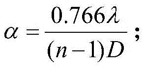
wherein λ is the wavelength of the incident laser, n is the refractive index of the diffraction axicon at the wavelength λ, and D is the size of a central diffraction-free bright spot formed after the incident laser passes through the diffraction axicon;
etching a plurality of steps on the diffraction axicon;
the etching line width of the step is d, the etching depth is h, then h is lambda/2 (n-1), and tan α is h/d;
and the incident laser passes through the diffraction axicon and then passes through the focusing lens for focusing and imaging.
2. The method of claim 1, wherein the incident laser light after passing through the diffractive axicon forms a central non-diffractive speckle having a size D of: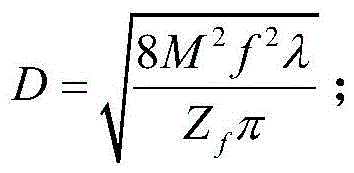
wherein M is2Is the beam quality of the incident laser light, f is the focal length of the focusing mirror, ZfIs the preset system focal depth.
Priority Applications (1)
| Application Number | Priority Date | Filing Date | Title |
|---|---|---|---|
| CN201711132189.XA CN107643596B (en) | 2017-11-15 | 2017-11-15 | Binary zone plate type diffraction axicon lens system and long focal depth imaging method thereof |
Applications Claiming Priority (1)
| Application Number | Priority Date | Filing Date | Title |
|---|---|---|---|
| CN201711132189.XA CN107643596B (en) | 2017-11-15 | 2017-11-15 | Binary zone plate type diffraction axicon lens system and long focal depth imaging method thereof |
Publications (2)
| Publication Number | Publication Date |
|---|---|
| CN107643596A CN107643596A (en) | 2018-01-30 |
| CN107643596B true CN107643596B (en) | 2020-03-13 |
Family
ID=61126103
Family Applications (1)
| Application Number | Title | Priority Date | Filing Date |
|---|---|---|---|
| CN201711132189.XA Active CN107643596B (en) | 2017-11-15 | 2017-11-15 | Binary zone plate type diffraction axicon lens system and long focal depth imaging method thereof |
Country Status (1)
| Country | Link |
|---|---|
| CN (1) | CN107643596B (en) |
Families Citing this family (4)
| Publication number | Priority date | Publication date | Assignee | Title |
|---|---|---|---|---|
| CN109031682A (en) * | 2018-07-10 | 2018-12-18 | 北京润和微光科技有限公司 | The generation system and method for Diode laser, small spot based on diffraction optical element |
| CN110850591B (en) * | 2019-10-25 | 2021-08-27 | 昆明理工大学 | Analytic description method of annular structured light |
| CN112034627B (en) * | 2020-08-11 | 2023-06-23 | 北京润和微光科技有限公司 | DOE-based focusing circular ring light spot generation method and system |
| CN114994928B (en) * | 2022-05-12 | 2024-09-13 | 成都莱普科技股份有限公司 | Oblique multi-focus generating system and method based on diffraction optical element |
Citations (3)
| Publication number | Priority date | Publication date | Assignee | Title |
|---|---|---|---|---|
| CN104865706A (en) * | 2015-05-21 | 2015-08-26 | 中国科学院光电技术研究所 | Device for improving quality of coherent combined beam laser beam |
| WO2015189240A1 (en) * | 2014-06-11 | 2015-12-17 | Hans-Ulrich Dodt | Light sheet microscopy using meso-optical elements |
| CN106444052A (en) * | 2016-11-16 | 2017-02-22 | 华侨大学 | Optical system capable of generating order-adjustable defocused beams |
-
2017
- 2017-11-15 CN CN201711132189.XA patent/CN107643596B/en active Active
Patent Citations (3)
| Publication number | Priority date | Publication date | Assignee | Title |
|---|---|---|---|---|
| WO2015189240A1 (en) * | 2014-06-11 | 2015-12-17 | Hans-Ulrich Dodt | Light sheet microscopy using meso-optical elements |
| CN104865706A (en) * | 2015-05-21 | 2015-08-26 | 中国科学院光电技术研究所 | Device for improving quality of coherent combined beam laser beam |
| CN106444052A (en) * | 2016-11-16 | 2017-02-22 | 华侨大学 | Optical system capable of generating order-adjustable defocused beams |
Non-Patent Citations (2)
| Title |
|---|
| 用于产生Bessel光的广义轴棱锥;李冬等;《华侨大学学报(自然科学版)》;20130930;第34卷(第5期);第500-503页 * |
| 轴棱锥-透镜系统产生局域空心光束中心亮斑的消除;张前安等;《物理学报》;20120205(第3期);第034205-1页-第034205-4页 * |
Also Published As
| Publication number | Publication date |
|---|---|
| CN107643596A (en) | 2018-01-30 |
Similar Documents
| Publication | Publication Date | Title |
|---|---|---|
| CN107643596B (en) | Binary zone plate type diffraction axicon lens system and long focal depth imaging method thereof | |
| US9323052B2 (en) | Lithography pupil shaping optical system and method for generating off-axis illumination mode | |
| CN105278011B (en) | Optical fiber laser collimating and shaping device, and design method thereof | |
| CN104570341B (en) | A kind of method and apparatus for synthesizing Beams in Conical Lenses shadow region | |
| JP2011048361A (en) | Diffractive laser beam homogenizer including photosensitive material and method for fabricating the same | |
| CN102841451A (en) | Device for generating vector light beam through annular combination half wave plate | |
| CN110554510A (en) | An optical imaging system of a transmissive diffractive optical element | |
| CN115826254B (en) | Flat-top beam modulation method, system and storage medium | |
| US9547176B2 (en) | Device for generating laser radiation having a linear intensity distribution | |
| CN204154997U (en) | A kind of laser homogenizing system | |
| CN109031682A (en) | The generation system and method for Diode laser, small spot based on diffraction optical element | |
| CN105467601A (en) | Method of utilizing binary zone plate to design diffraction multi-focus element and realize axial direction multi-focus optical path structure | |
| CN109782451B (en) | A method and system for realizing pyramid field shaping using beam spatial coherence structure | |
| CN108535865A (en) | A kind of negative refraction grating plano-concave mirror design method that focal length is controllable | |
| Yang et al. | Analysis and optimization on single-zone binary flat-top beam shaper | |
| CN106646896A (en) | Flow cytometer light beam shaping system based on gradient refractive index lens | |
| CN104600566A (en) | High beam quality of semiconductor laser array beam combination device | |
| JP4917123B2 (en) | Laser beam optical system and laser processing apparatus | |
| CN210573037U (en) | An Optical Imaging System Based on Reflective Diffractive Optical Elements | |
| CN103887707B (en) | A kind of semiconductor laser with high-power high light beam quality laser | |
| CN119216767A (en) | Femtosecond laser multi-focus parallel processing method, device and fiber grating writing method | |
| CN116213920B (en) | A high depth-to-diameter ratio micro-hole machining device and method with time-space shaping function | |
| GB2512323A (en) | Laser beam intensity profile modulator for top hat beams | |
| CN115036782B (en) | Vortex beam, flat-top beam and Gaussian beam switching method and solid laser | |
| KR101667792B1 (en) | Optical apparatus using interference beam |
Legal Events
| Date | Code | Title | Description |
|---|---|---|---|
| PB01 | Publication | ||
| PB01 | Publication | ||
| SE01 | Entry into force of request for substantive examination | ||
| SE01 | Entry into force of request for substantive examination | ||
| GR01 | Patent grant |