Drawings
The above-mentioned and other features and advantages of this invention, and the manner of attaining them, will become more apparent and the invention will be better understood by reference to the following description of embodiments of the invention taken in conjunction with the accompanying drawings, wherein:
FIG. 1 is a perspective view of an embodiment of a microfluidic dispensing device according to the present invention in an environment containing an external magnetic field generator.
Fig. 2 is another perspective view of the microfluidic dispensing device of fig. 1.
Fig. 3 is an orthogonal top view of the microfluidic dispensing device of fig. 1 and 2.
Fig. 4 is an orthogonal side view of the microfluidic dispensing device of fig. 1 and 2.
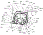
Fig. 5 is an orthogonal end view of the microfluidic dispensing device of fig. 1 and 2.
Fig. 6 is an exploded perspective view of the micro-fluid dispensing device of fig. 1 and 2 oriented for viewing the chamber of the body in a direction toward the ejection chip.
Fig. 7 is another exploded perspective view of the micro-fluid dispensing device of fig. 1 and 2 oriented for viewing in a direction away from the ejection chip.
Fig. 8 is a cross-sectional view of the microfluidic dispensing device of fig. 1 taken along line 8-8 of fig. 5.
Fig. 9 is a cross-sectional view of the microfluidic dispensing device of fig. 1 taken along line 9-9 of fig. 5.
Fig. 10 is a perspective view of the microfluidic dispensing device of fig. 1 with end caps and covers removed to expose the body/baffle assembly.
FIG. 11 is a perspective view of the depiction of FIG. 10 in which the baffles are removed to expose the guides and stir bars contained in the body relative to the first and second planes and the direction of fluid ejection.
Fig. 12 is an orthogonal view of the body/guide/stir bar arrangement of fig. 11 as viewed in a direction into the body of the chamber toward the bottom wall of the body.
FIG. 13 is an orthogonal end view of the body of FIG. 11 containing the guide and stir bar as viewed in a direction toward the outer wall and opening of the body.
Fig. 14 is a cross-sectional view of the body/guide/stir bar arrangement of fig. 12 and 13, taken along line 14-14 of fig. 13.
Fig. 15 is an enlarged cross-sectional view of the body/guide/stir bar arrangement of fig. 12 and 13, taken along line 15-15 of fig. 13.
FIG. 16 is an enlarged view of the depiction of FIG. 12 with the guide removed to expose the stir bar present in the chamber of the body.
Fig. 17 is a top view of another embodiment of a microfluidic dispensing device according to the present invention.
FIG. 18 is a cross-sectional view of the microfluidic dispensing device of FIG. 17 taken along line 18-18 of FIG. 17.
Fig. 19 is an exploded perspective view of the micro-fluid dispensing device of fig. 17 oriented for viewing the chamber of the body in a direction toward the ejection chip.
Fig. 20 is another perspective view of the microfluidic dispensing device of fig. 17 shown with respect to the first and second planes and the direction of fluid ejection with the end caps, covers, and spacers removed to expose guides and stir bars contained in the body.
FIG. 21 is an orthogonal top view corresponding to the perspective of FIG. 20 showing a body having a chamber with a guide and a stir bar.
FIG. 22 is an orthogonal side view of the body of the microfluidic dispensing device of FIG. 17, wherein the body contains a guide and a stir bar.
Fig. 23 is a sectional view taken along line 23-23 of fig. 22.
Fig. 24 is a perspective view of an embodiment of a stir bar of the microfluidic dispensing device of fig. 17 as further depicted in fig. 18-21 and 23.
FIG. 25 is a top view of the stir bar of FIG. 24.
FIG. 26 is a side view of the stir bar of FIG. 24.
FIG. 27 is a cross-sectional view of the stir bar taken along line 27-27 of FIG. 25.
FIG. 28 is a perspective view of another embodiment of a stir bar suitable for use in the microfluidic dispensing device of FIG. 17.
FIG. 29 is a top view of the stir bar of FIG. 28.
FIG. 30 is a side view of the stir bar of FIG. 28.
FIG. 31 is a cross-sectional view of the stir bar taken along line 31-31 of FIG. 29.
FIG. 32 is an exploded perspective view of another embodiment of a stir bar suitable for use in the microfluidic dispensing device of FIG. 17.
FIG. 33 is a top view of the stir bar of FIG. 32.
FIG. 34 is a side view of the stir bar of FIG. 32.
FIG. 35 is a cross-sectional view of the stir bar taken along line 35-35 of FIG. 33.
FIG. 36 is an exploded perspective view of another embodiment of a stir bar suitable for use in the microfluidic dispensing device of FIG. 17.
FIG. 37 is a top view of the stir bar of FIG. 36.
FIG. 38 is a side view of the stir bar of FIG. 36.
FIG. 39 is a cross-sectional view of the stir bar taken along line 39-39 of FIG. 37.
FIG. 40 is an exploded perspective view of another embodiment of a stir bar suitable for use in the microfluidic dispensing device of FIG. 17.
FIG. 41 is a top view of the stir bar of FIG. 40.
FIG. 42 is a side view of the stir bar of FIG. 40.
FIG. 43 is a cross-sectional view of the stir bar taken along line 43-43 of FIG. 41.
FIG. 44 is a top view of another embodiment of a stir bar suitable for use in the microfluidic dispensing device of FIG. 17.
FIG. 45 is a side view of the stir bar of FIG. 45.
FIG. 46 is a cross-sectional view of the stir bar taken along line 46-46 of FIG. 44.
Fig. 47 is an x-ray image of a microfluidic dispensing device configured according to fig. 17-23, depicting a suitable suspension of particles in a fluid, such as a freshly filled microfluidic dispensing device, or after implementing the methods of the present invention to remix the fluid in a reservoir.
Fig. 48 is an x-ray image of a micro-fluidic dispensing device having a longitudinal extent of a housing arranged along a vertical axis and showing accumulation of precipitated particles in a low gravity region of a reservoir configured according to fig. 17-23.
Fig. 49 is an x-ray image of the micro-fluidic dispensing device of fig. 48, tilted off-axis from the vertical axis to depict how settled particles migrate to a new low gravity region of the reservoir based on orientation changes.
Fig. 50 is an x-ray image of a micro-fluid dispensing device configured according to fig. 17-23, wherein the ejection chip is facing vertically downward and settled particles have accumulated on the channel inlets and channel outlets of the fluid channels feeding the ejection chip.
Fig. 51 is a perspective view of the microfluidic dispensing device of fig. 17-23, shown in cartesian space with X, Y and a Z-axis, with the longitudinal extent of the housing on the positive Z-axis and the lateral extent of the housing on the X-Y plane.
Fig. 52 shows the micro-fluid dispensing device depicted in fig. 18, oriented 135 degrees upward in the direction of fluid ejection, with the exterior of the dome portion of the septum facing upward and the exterior of the bottom wall facing downward.
FIG. 53 shows the micro-fluid dispensing device depicted in FIG. 18 in an orientation in which the fluid ejection direction is at 45 degrees, and the exterior of the domed portion of the septum faces downward at 45 degrees from vertical, while the exterior of the bottom wall faces upward at 45 degrees from vertical.
FIG. 54 is a block diagram of an external magnetic field generator for rotating a stir bar and having a sensor in various embodiments of the present invention.
Fig. 55 is a schematic diagram of the angular rotational position of the stirring rod (with magnets) relative to the angular rotational position of the rotating magnetic field.
FIG. 56 is a schematic and diagrammatic depiction of a scenario in which the torque required to rotate the stir bar is too high to begin stir bar rotation (i.e., the stir bar is stuck and cannot rotate).
FIG. 57 is a schematic and diagrammatic depiction of a scenario in which there is approximately a 45 degree phase lag between the angular rotational position of the stir bar and the angular rotational position of the rotating magnetic field.
FIG. 58 is a schematic and diagrammatic depiction of a scenario in which there is a phase lag of approximately 90 degrees (shown as arcuate arrowed lines) between the angular rotational position of the stir bar and the angular rotational position of the rotating magnetic field.
FIG. 59 is a flow chart of a method of operating a stir bar in a fluid dispensing apparatus according to one aspect of the present invention.
FIG. 60 is a further enlargement of a portion of the description of FIG. 23 illustrating the location of stagnation zones in the fluid channel.
FIG. 61 is an enlarged bottom view of a portion of the guide of FIG. 21 showing the flow control portion with an inlet deflector element and an outlet deflector element.
FIG. 62 is an enlarged perspective bottom view of the guide of FIG. 21 at an orientation showing several surfaces of the flow control portion and the inducer component.
FIG. 63 is an enlarged perspective bottom view of the guide portion of FIG. 21 at an orientation showing several surfaces of the flow control portion and the exducer member.
FIG. 64 is an orthogonal side view of another embodiment of a microfluidic dispensing device having features that reduce the occurrence of stagnant zones in the fluid channel.
Fig. 65 is an orthogonal top view of the microfluidic dispensing device of fig. 51.
FIG. 66 is a cross-sectional view of the microfluidic dispensing device taken along line 66-66 of FIG. 64.
FIG. 67 is a cross-sectional view of the microfluidic dispensing device taken along line 67-67 of FIG. 64.
Fig. 68 is an enlargement of a portion of the description of fig. 67.
FIG. 69 is a cross-sectional view of the microfluidic dispensing device taken along line 69-69 of FIG. 65.
FIG. 70 is a cross-sectional view of the microfluidic dispensing device taken along line 70-70 of FIG. 65.
Fig. 71 is an enlargement of a portion of the description of fig. 70.
Fig. 72 is a perspective view of the microfluidic dispensing device of fig. 1 with the end cap and cover removed to expose the body/diaphragm assembly relative to the first and second planes and relative to the fluid ejection direction, and a portion of the diaphragm exploded for illustration of the reservoir.
FIG. 73 is an orthogonal top view of the body/baffle assembly of FIG. 72.
FIG. 74 is a cross-sectional view of the body/baffle assembly of FIG. 72, taken along line 74-74 of FIG. 73 to expose a plurality of stir bars located in a reservoir.
Fig. 75 is a perspective view of the depiction of fig. 72, wherein the baffles are removed to expose a plurality of stir bars contained in the body, and the spray chips are removed to expose fluid openings in the outer wall.
Fig. 76 is another perspective view of the depiction of fig. 75, in an orientation to show the channel inlets and channel outlets of the fluid channels.
Fig. 77 is an orthogonal top view of the body/agitator bar assembly of fig. 75 and 76.
FIG. 78 is a schematic view of the two stir bars depicted in FIGS. 73-77 illustrating the overlap of a first rotational region of the first stir bar with a second rotational region of the second stir bar.
Fig. 79 is a perspective view of an alternative body with a dividing wall that can replace the body depicted in fig. 1-5 and 72-77.
FIG. 80 is another perspective view of the depiction of FIG. 79, in an orientation relative to the partition wall for illustrating the channel inlet and the channel outlet of the fluid channel.
Fig. 81 is a perspective view of a depiction of an alternative body corresponding to fig. 79 and 80, with two stirring rods inserted on opposite sides of the dividing wall.
FIG. 82 is an orthogonal top view of the alternative body and agitator bar assembly of FIG. 81.
Fig. 83 is a cross-sectional view of the alternative body of fig. 79-82 taken along line 83-83 of fig. 82.
Fig. 84 is a sectional view of fig. 83 modified to include a sectional view of the partition of fig. 72-74 mounted on the alternate body of fig. 79-83.
Fig. 85 is an enlarged portion of the depiction of fig. 82, showing a divider wall separating a first rotational region of a first stir bar from a second rotational region of a second stir bar.
Fig. 86 is a perspective view of the depiction of fig. 72, wherein the baffles are removed to expose the stir bar contained in the body and the spray chip is removed to expose the fluid openings in the outer wall.
Fig. 87 is another perspective view of the depiction of fig. 72, in an orientation to show the channel inlets and channel outlets of the fluid channels.
Fig. 88 is an orthogonal view of the body/stir bar arrangement of fig. 86 and 87 as viewed in a direction into the body of the chamber toward the bottom wall of the body.
Fig. 89 is a cross-sectional view of the body/stir bar arrangement of fig. 88 taken along line 89-89 of fig. 88.
Fig. 90 is a top view of another embodiment of a microfluidic dispensing device according to the present invention.
FIG. 91 is a cross-sectional view of the microfluidic dispensing device of FIG. 90 taken along line 91-91 of FIG. 90.
Fig. 92 is another perspective view of the microfluidic dispensing device of fig. 90 with the end cap, cover, and spacer removed for illustrating the range of motion of the movable stir bar relative to the guide.
Fig. 93 is another perspective view of the microfluidic dispensing device of fig. 90 with the end cap, cover, and septum removed to expose a guide and movable stir bar contained in the body, shown with respect to the first and second planes and the fluid ejection direction.
FIG. 94 is an orthogonal top view corresponding to the perspective view of FIG. 93, showing a body having a guide and a movable stir bar, and showing the range of motion of the movable stir bar relative to the guide.
FIG. 95 is an orthogonal side view of the body of the microfluidic dispensing device of FIG. 90, wherein the body contains a guide and a movable stir bar.
Fig. 96 is a sectional view taken along line 96-96 of fig. 95.
Fig. 97 is a perspective view of an embodiment of a stir bar of the microfluidic dispensing device of fig. 90 as further depicted in fig. 91-94 and 96.
Fig. 98 is a top view of the stir bar of fig. 97.
Fig. 99 is a side view of the stir bar of fig. 97.
FIG. 100 is a cross-sectional view of the stirring rod of FIG. 97 taken along line 100 of FIG. 98.
Corresponding reference characters indicate corresponding parts throughout the several views. The exemplifications set out herein illustrate embodiments of the invention, and such exemplifications are not to be construed as limiting the scope of the invention in any manner.
Description of the reference numerals
110. 210, 750: a microfluidic dispensing device;
112. 212, 752: a housing;
114: a tape automated bonding circuit;
116: a flexible circuit;
118: ejecting the chip;
120: a spray nozzle;
120-1: a fluid ejection direction;
122. 200, 214, 754: a main body;
122-1, 214-1: filling the hole;
124. 216, 756: a cover;
124-1, 216-1: an exhaust hole;
126. 218: an end cap;
128. 220, and (2) a step of: filling;
130. 222, 758: a partition plate;
130-1, 222-1: a dome portion;
132. 135, 224, 300, 400-1, 500-1, 760: a stirring rod;
132-1, 132-2, 132-3, 132-4, 135-1, 135-2, 135-3, 135-4, 252, 254, 256, 258, 352, 354, 356, 358, 452, 454, 456, 458, 552, 554, 556, 558, 760-1, 760-2, 760-3, 760-4: a paddle;
132-5, 135-5, 212-1, 212-2, 212-3, 212-4: a free end tip;
132-6, 135-6: a leading edge inclined surface;
132-7, 135-7: a trailing edge inclined surface;
134. 226: a guide section;
136. 228, 762: a liquid storage chamber;
136-1, 228-1: a proximal continuous 1/3 volume portion;
136-2, 228-2: a central continuous 1/3 volume portion;
136-3, 228-3: a distally continuous 1/3 volumetric portion;
136-4: a continuous 2/3 volume portion;
138. 230, 764: a bottom wall;
138-1: a circular recessed area;
140. 232 and 766: an outer perimeter wall;
140-1, 232-1, 766-1: an outer wall;
140-2, 232-2, 766-2: a chip mounting surface;
140-3, 232-3, 766-3: a fluid opening;
142. 146, 234, 236: a plane;
144: a sealing strip of adhesive;
148. 238, 768: a chamber;
208. 208-1, 208-2, 208-3, 208-4, 208-5, 148-1, 238-1: a transverse opening;
150. 240, 770: an inner perimeter wall;
150-1, 240-1, 614-1, 616-1, 610-2, 612-2, 770-1: a proximal end;
150-2, 240-2, 614-2, 616-2, 610-3, 612-3, 770-2: a distal end;
150-3, 240-3, 770-3: a peripheral end face;
240-4, 240-5: an inner peripheral wall portion;
152. 242, 776: an inlet fluid port;
152-1, 242-1: an inclined entrance ramp;
154. 244, 778: an outlet fluid port;
154-1, 244-1: an inclined exit ramp;
156. 246, 780: a fluid channel;
246-6, 780-3: a passage;
156-1, 246-1, 780-1: a channel inlet;
156-2, 246-2, 780-2: a channel outlet;
156-3, 246-3: a convex arcuate wall;
156-4, 156-5, 246-4, 246-5: a radius of transposition;
246-7: an outer wall structure;
246-3, 246-4, 246-5: an inner wall structure;
246-8: a first inflection point structure;
246-9: a second inflection point structure;
158. 248, 782: a channel midpoint;
160. 165, 250, 350, 450, 550, 772: a rotating shaft;
160-1, 165-1, 250-1: the direction of rotation;
162. 167, 260, 360, 460, 560: a magnet;
164. 168: an external magnetic field generator;
164-1: a microcontroller;
164-2: an electromagnetic field rotator;
164-3: an electromagnetic field generator;
164-4: a sensor;
164-5: an onboard non-transitory electronic memory;
164-6: a profile database;
166. 278: an annular member;
278-3, 279-3: an axial restraining surface;
166-1: a first annular surface;
166-2: a second annular surface;
166-3, 278-1: an opening;
166-4, 278-2: an annular limiting surface;
168-1, 168-2, 280-5, 280-6, 280-7, 280-8: a positioning feature;
170. 172: a biasing member;
172-1, 284: a first retention feature;
214-2: a second retention feature;
174: a cage structure;
176. 282: a central shaft;
178: an offset leg;
180: an axial restraining portion;
182. 214-2: a second retention feature;
184. 286: a flow control section;
184-1, 286-1: a flow separator feature;
184-2, 286-2: a flow recombination characteristic;
184-3, 286-3: a concave arcuate surface;
204: a first region;
206: a second region;
211. 211-1, 211-2, 211-3, 211-4: a column;
279: a regulating member;
279-1: a guide opening;
279-2: an inner radial limiting surface;
286-4: an inlet port wall portion;
286-5: an outlet port wall portion;
262. 362, 462, 562: an axial extent;
264. 364, 464, 564: a first layer portion;
266. 366, 466, 566: a second layer portion;
268. 368, 468, 568: a first radial extent;
270. 370, 470, 570: a first distal tip;
270-1, 370-1, 470-1, 570-1: a first tip portion;
272. 372, 472, 572: a second radial extent;
274. 374, 474, 574: a second distal tip;
274-1, 374-1, 474-1, 574-1: a second tip portion;
276: a convex surface;
280-1, 280-2, 280-3, 280-4: mounting an arm;
283-1: a longitudinal extent;
283-2: a lateral extent;
376. 476: a flat surface;
478. 578: a void;
480. 480-1, 580: a membrane seal;
580-1: a permanent cover;
502: a cylindrical axle;
576: a convex curved surface;
600: a vertical axis;
602: a fluid;
606: a low gravity region;
604: precipitating the particles;
608: angular amount;
610. 612: a new low gravity region;
650: an inlet sidewall;
652: an outlet sidewall;
654: a distal wall portion;
656: a first stagnation zone;
658: a second stagnation zone;
660: an inlet flow director component;
660-1: an inlet deflector wall portion;
660-5: a first inlet ceiling portion;
660-6: a second inlet ceiling portion;
662: an outlet flow director component;
662-1: a second outlet wall portion;
662-5: a first outlet ceiling portion;
662-6: a second outlet ceiling portion;
664-3: a first height;
664-4: a first vertex;
666-3, 660-4, 662-4: a height;
666-4: a second vertex;
202. 720-4: a partition wall;
700: rotating the magnetic field;
702: stir bar magnet strength profile;
704: a magnetic field strength profile;
706: a composite magnetic strength profile;
710: a composite magnetic strength profile;
712: stir bar magnet strength profile;
714: a composite magnetic strength profile;
784: an inlet transition passage;
786-1: direction;
788. 789, 790, 792, 794, 798, 799, 750, 752, 754: a surface;
788. 798: a ramp layer;
788-1, 798-1: a first transition ramp portion;
788-2, 798-2: a second transition ramp portion;
780-4, 789, 799: an inner wall;
790. 800: a conical top plate;
792. 802: a gusseted roof portion;
794. 804: an inclined side wall;
795: an inner surface;
796: a transition outlet passage.
Detailed Description
Referring now to the drawings, and more particularly to fig. 1-16, there is shown a fluid dispensing device, which in this example is a microfluidic dispensing device 110 according to an embodiment of the present invention.
Referring to fig. 1-5, a microfluidic dispensing device 110 generally includes a housing 112 and a Tape Automated Bonding (TAB) circuit 114. The micro-fluid dispensing device 110 is configured to contain a supply of fluid, e.g., a fluid containing particulate material, and the TAB circuit 114 is configured to facilitate ejection of the fluid from the housing 112. The fluid may be, for example, a cosmetic, a lubricant, a paint, an ink, or the like.
Referring also to fig. 6 and 7, the TAB circuit 114 includes a flexible circuit 116 to which the ejector chip 118 is mechanically and electrically connected. The flex circuit 116 provides electrical connection to an electrical driver device (not shown), such as an inkjet printer, that is configured to operate the ejection chip 118 to eject fluid contained within the housing 112. In the present embodiment, the ejection chip 118 is configured as a plate-like structure having a planar extent formed generally as a nozzle plate layer and a silicon layer, as is well known in the art. The nozzle plate layer of the jet chip 118 has a plurality of jet nozzles 120 oriented such that the fluid jet direction 120-1 is substantially orthogonal to the planar extent of the jet chip 118. An ejection mechanism, such as an electrical heater (thermal) or piezoelectric (electromechanical) device, is associated with each of the ejection nozzles 120 at the silicon layer of the ejection chip 118. The operation of such ejection chip 118 and drivers is well known in micro-fluid ejection technology, such as ink jet printing.
As used herein, each of the terms "substantially orthogonal" and "substantially perpendicular" are defined to mean an angular relationship of 90 degrees plus or minus 10 degrees between two elements. The term "substantially parallel" is defined to mean an angular relationship of zero degrees plus or minus 10 degrees between two elements.
As best shown in fig. 6 and 7, the housing 112 contains a body 122, a cover 124, an end cap 126, and a packing 128 (e.g., a ball). The baffle 130, the stir bar 132, and the guide 134 are contained within the housing 112. Each of the housing 112 assembly, the stir bar 132, and the guide 134 can be made of plastic using a molding process. The spacer 130 is made of rubber using a molding process. Further, in this embodiment, the packing 128 may take the form of a stainless steel ball bearing.
Referring also to fig. 8 and 9, in general, fluid (not shown) is loaded into the sealed area between the body 122 and the diaphragm 130, i.e., the reservoir 136, through the fill hole 122-1 in the body 122 (see also fig. 6). A back pressure in the reservoir 136 is set and then maintained by inserting, e.g., pressing, the bung 128 into the fill hole 122-1 to prevent air from leaking into the reservoir 136 or fluid from leaking out of the reservoir 136. The end cap 126 is then placed on the end of the body 122/cap 124 combination opposite the jet chip 118. The stir bar 132 resides in a sealed fluid-containing reservoir 136 between the body 122 and the diaphragm 130. The internal fluid flow may be created within the reservoir 136 by rotating the stir bar 132 to provide fluid mixing and redistribution of particles in the fluid within the sealed region of the reservoir 136.
Referring now also to fig. 10-16, the body 122 of the housing 112 has a bottom wall 138 and an outer peripheral wall 140 adjacent the bottom wall 138. An outer peripheral wall 140 is oriented to extend from the bottom wall 138 in a direction substantially orthogonal to the bottom wall 138. The lid 124 is configured to engage the outer perimeter wall 140. Accordingly, the outer peripheral wall 140 is interposed between the bottom wall 138 and the lid 124, with the lid 124 being attached to the open free end of the outer peripheral wall 140 by welding, adhesive, or other securing mechanism (e.g., snap fitting or threaded fitting). After the partition 130, the stirring rod 132, and the guide 134 are installed in the body 122, the cover 124 is attached to the body 122.
The outer perimeter wall 140 of the body 122 comprises an outer wall 140-1 that is an adjacent portion of the outer perimeter wall 140. The outer wall 140-1 has a chip mounting surface 140-2 defining a plane 142 (see fig. 11 and 12) and has a fluid opening 140-3 adjacent the chip mounting surface 140-2 through the thickness of the outer wall 140-1. The ejection chip 118 is mounted to the chip mounting surface 140-2, such as by an adhesive bead 144 (see fig. 6 and 7) and is in fluid communication with the fluid opening 140-3 (see fig. 13) of the outer wall 140-1. Thus, the planar extent of the jet chip 118 is oriented along the plane 142, with the plurality of jet nozzles 120 oriented such that the fluid jet direction 120-1 is substantially orthogonal to the plane 142. The bottom wall 138 is oriented along a plane 146 (see fig. 11) that is substantially orthogonal to the plane 142 of the outer wall 140-1. As best shown in fig. 6, 15, and 16, the bottom wall 138 may include a circular recessed area 138-1 near the desired location of the stir bar 132.
Referring to fig. 11-16, the body 122 of the housing 112 also includes a chamber 148 located within the boundary defined by the outer perimeter wall 140. The chamber 148 forms a portion of the reservoir 136 and is configured to define an interior space, and in particular, includes a bottom wall 138 and has an interior peripheral wall 150 configured with rounded corners to facilitate fluid flow in the chamber 148. The inner peripheral wall 150 of the chamber 148 has an extent bounded by a proximal end 150-1 and a distal end 150-2. The proximal end 150-1 is adjacent the bottom wall 138 and may form an index radius with the bottom wall 138. This edge radius may promote mixing effects by reducing the number of sharp angles. The distal end 150-2 is configured to define a peripheral end face 150-3 at the transverse opening 148-1 of the chamber 148. The peripheral end face 150-3 may include a plurality of peripheral ribs or corrugations to provide an effective sealing surface for engagement with the separator plate 130. The extent of the inner peripheral wall 150 of the chamber 148 is substantially orthogonal to the bottom wall 138 and substantially parallel to the corresponding extent of the outer peripheral wall 140 (see fig. 6).
As best shown in fig. 15 and 16, the chamber 148 has an inlet fluid port 152 and an outlet fluid port 154, each of which is formed in a portion of the inner peripheral wall 150. The terms "inlet" and "outlet" are convenient terms for distinguishing between the multiple ports of the present embodiment, and are related to the particular direction of rotation of the stir bar 132. However, it should be understood that the direction of rotation of the stir bar 132 specifies whether a particular port acts as an inlet port or an outlet port, and it is within the scope of the present invention to reverse the direction of rotation of the stir bar 132 and thus reverse the action of the respective port within the chamber 148.
The inlet fluid port 152 is spaced a distance from the outlet fluid port 154 along a portion of the inner peripheral wall 150. As best shown in fig. 15 and 16, in general, the body 122 of the housing 112 contains a fluid channel 156 that is interposed between a portion of the inner peripheral wall 150 of the chamber 148 and the outer wall 140-1 of the outer peripheral wall 140 that carries the ejector chip 118.
The fluid channels 156 are configured to minimize particle settling in the area of the ejection chip 118. The fluid channels 156 are sized, for example, using empirical data, to provide a desired flow rate while also maintaining an acceptable flow rate for the fluids mixed through the fluid channels 156.
In the present embodiment, referring to FIG. 15, the fluid channel 156 is configured as a U-shaped elongated channel having a channel inlet 156-1 and a channel outlet 156-2. The size (e.g., height and width) and shape of the fluid channel 156 is selected to provide a desired combination of fluid flow and flow rate to promote agitation within the channel.
The fluid channel 156 is configured to connect the inlet fluid port 152 of the chamber 148 in fluid communication with the outlet fluid port 154 of the chamber 148, and also to connect the fluid opening 140-3 of the outer wall 140-1 of the outer peripheral wall 140 in fluid communication with both the inlet fluid port 152 and the outlet fluid port 154 of the chamber 148. Specifically, channel inlet 156-1 of fluid channel 156 is positioned adjacent inlet fluid port 152 of chamber 148, and channel outlet 156-2 of fluid channel 156 is positioned adjacent outlet fluid port 154 of chamber 148. In this embodiment, the inlet fluid port 152 and the outlet fluid port 154 of the chamber 148 are symmetrical in configuration.
The fluid channel 156 has a convex arcuate wall 156-3 between the channel inlet 156-1 and the channel outlet 156-2, wherein the fluid channel 156 is symmetrical about a channel midpoint 158. The convex arcuate wall 156-3 of the fluid channel 156 is in turn located between the inlet fluid port 152 and the outlet fluid port 154 of the chamber 148 on the opposite side of the inner peripheral wall 150 from the interior space of the chamber 148, with the convex arcuate wall 156-3 positioned to face the fluid opening 140-3 of the outer wall 140-1 and the ejection chip 118.
The convex arcuate wall 156-3 is configured to form a fluid flow through the fluid channel 156 that is substantially parallel to the jet chip 118. In this embodiment, the longitudinal extent of the convex arcuate wall 156-3 has a radius that faces the fluid opening 140-3 and is substantially parallel to the ejection chip 118, and has index radii 156-4, 156-5 that are positioned adjacent to the channel inlet 156-1 and channel outlet 156-2, respectively. The radii of the convex arcuate wall 156-3 and the index radii 156-4, 156-5 contribute to fluid flow efficiency. The distance between convex arcuate wall 156-3 and fluid ejecting chip 118 is narrowest at a channel midpoint 158, which coincides with the midpoint of the longitudinal extent of ejecting chip 118, and in turn coincides with the midpoint of the longitudinal extent of fluid opening 140-3 of outer wall 140-1.
Each of the inlet and outlet fluid ports 152, 154 of the chamber 148 has an inclined ramp structure configured such that each of the inlet and outlet fluid ports 152, 154 converge in a respective direction toward the fluid passage 156. Specifically, the inlet fluid port 152 of the chamber 148 has an inclined inlet ramp 152-1 configured such that the inlet fluid port 152 converges in a direction toward the channel inlet 156-1 of the fluid channel 156, i.e., narrows, and the outlet fluid port 154 of the chamber 148 has an inclined outlet ramp 154-1 that diverges in a direction away from the channel outlet 156-2 of the fluid channel 156, i.e., widens.
Referring again to fig. 6-10, the partition 130 is disposed between the lid 124 and the peripheral end face 150-3 of the interior peripheral wall 150 of the chamber 148. The attachment of the cover 124 to the body 122 compresses the perimeter of the diaphragm 130, thereby forming a continuous seal between the diaphragm 130 and the body 122. More specifically, the partition 130 is configured for sealing engagement with the peripheral end face 150-3 of the inner peripheral wall 150 of the chamber 148 when the reservoir 136 is formed. Thus, the chamber 148 and the diaphragm 130 cooperate in combination to define the reservoir 136 having a variable volume.
Referring specifically to fig. 6, 8 and 9, the outer surface of the diaphragm 130 is connected to the atmosphere through a vent 124-1 located in the lid 124 so that a controlled negative pressure can be maintained in the reservoir 136. The septum 130 is made of rubber and includes a domed portion 130-1 configured to gradually collapse toward the bottom wall 138 as fluid is consumed from the microfluidic dispensing device 110 such that a desired negative pressure in the chamber 148 is maintained and thereby the effective volume of the variable volume of the reservoir 136 is varied.
For further illustration, referring to fig. 8 and 9, the variable volume (also referred to herein as the majority region) of liquid storage chamber 136 may be considered hereinafter to have a proximal continuous 1/3 volume portion 136-1 and a continuous 2/3 volume portion 136-4 formed by a central continuous 1/3 volume portion 136-2 and a distal continuous 1/3 volume portion 136-3, wherein central continuous 1/3 volume portion 136-2 separates proximal continuous 1/3 volume portion 136-1 from distal continuous 1/3 volume portion 136-3. The proximal continuous 1/3 volume portion 136-1 is located closer to the ejection chip 118 than the continuous 2/3 volume portion 136-4, which continuous 2/3 volume portion 136-4 is formed by the central continuous 1/3 volume portion 136-2 and the distal continuous 1/3 volume portion 136-3.
Referring to fig. 6-9 and 16, the stir bar 132 resides within the variable volume of the reservoir 136 and the chamber 148, and is located within the boundary defined by the inner peripheral wall 150 of the chamber 148. The stir bar 132 has an axis of rotation 160 and a plurality of paddles 132-1, 132-2, 132-3, 132-4 extending radially away from the axis of rotation 160. The stir bar 132 has a magnet 162 (see FIG. 8), e.g., a permanent magnet, configured to interact with an external magnetic field generator 164 (see FIG. 1) to drive the stir bar 132 to rotate about the rotational axis 160. The principle of operation of the stir bar 132 is that when the magnet 162 is aligned with a sufficiently strong external magnetic field generated by the external magnetic field generator 164, then rotating the external magnetic field generated by the external magnetic field generator 164 in a controlled manner causes the stir bar 132 to rotate. Similar to the operation of the stepping motor, the external magnetic field generated by the external magnetic field generator 164 may be electrically rotated, or may be rotated by a rotation shaft. Thus, the stir bar 132 effectively provides mixing of the fluid in the reservoir 136 through rotation of the stir bar 132 about the axis of rotation 160.
The fluid mixing in most regions relies on the flow velocity generated by the rotation of the stir bar 132 to create shear stress at the sedimentary boundary layer of the particles. Remixing occurs when the shear stress is greater than the critical shear stress (empirically determined) for initiating particle motion because the precipitated particles are now distributed in the moving fluid. The shear stress depends on fluid parameters, such as viscosity, particle size and density; and mechanical design factors such as vessel shape, stir bar 132 geometry, fluid thickness between moving and stationary surfaces, and rotational speed.
In addition, the fluid flow is generated by rotating the stir bar 132 in the fluid region (e.g., the proximal contiguous 1/3 volume portion 136-1 and fluid channel 156 associated with the jet chip 118) to ensure that a majority of the mixed fluid is presented to the jet chip 118 for nozzle jetting and to move the fluid adjacent to the jet chip 118 to a majority of the fluid reservoir 136 to ensure that the channel fluid flowing through the fluid channel 156 mixes with a majority of the fluid reservoir 136 to produce a more homogeneous mixture. Although this flow is primarily distributed in nature, some mixing will occur if the flow rate is sufficient to produce shear stresses greater than a critical value.
The stir bar 132 induces a rotational flow of fluid around a central region associated with the axis of rotation 160 of the stir bar 132 primarily by some axial flow having a central return path as in a partial toroidal flow pattern.
Referring to FIG. 16, each of the plurality of paddles 132-1, 132-2, 132-3, 132-4 of the stir bar 132 has a respective free end tip 132-5. To reduce rotational resistance, each blade may contain an upper and lower symmetrical pair of chamfered surfaces, thereby forming a leading edge inclined surface 132-6 and a trailing edge inclined surface 132-7 with respect to the direction of rotation 160-1 of the stir bar 132. It is also contemplated that each of the plurality of paddles 132-1, 132-2, 132-3, 132-4 of the stir bar 132 may have a pill or cylindrical shape. In this embodiment, the stir bar 132 has two pairs of diametrically opposed paddles, wherein a first paddle of the diametrically opposed paddles has a first free end tip 132-5 and a second paddle of the diametrically opposed paddles has a second free end tip 132-5.
In the present embodiment, the four paddles that form two pairs of diametrically opposed paddles are equally spaced apart in 90 degree increments about the rotational axis 160. However, the actual number of paddles of stir bar 132 may be two or more, and preferably three or four, but more preferably four, with each adjacent pair of paddles having the same angular spacing about rotational axis 160. For example, a stir bar 132 configuration with three paddles may have a paddle spacing of 120 degrees, a stir bar 132 configuration with four paddles may have a paddle spacing of 90 degrees, and so on.
In the present embodiment and with the variable volume of the reservoir 136 divided into the proximal continuous 1/3 volume portion 136-1 and the continuous 2/3 volume portion 136-4 described above, wherein the proximal continuous 1/3 volume portion 136-1 is located closer to the ejection chip 118 than the continuous 2/3 volume portion 136-4, the axis of rotation 160 of the stir bar 132 may be located in the proximal continuous 1/3 volume portion 136-1 that is closer to the ejection chip 118. In other words, the guide portion 134 is configured to position the rotational axis 160 of the stir bar 132 in a portion of the interior space of the chamber 148 that constitutes the volume 1/3 of the interior space of the chamber 148 closest to the fluid opening 140-3.
Referring again to FIG. 11, the axis of rotation 160 of the stir bar 132 may be oriented in an angular range of plus or minus 45 degrees from perpendicular with respect to the fluid ejection direction 120-1. In other words, the axis of rotation 160 of the stir bar 132 may be oriented in an angular range of plus or minus 45 degrees from parallel to a planar range (e.g., the plane 142) of the jet chip 118. In combination, the axis of rotation 160 of the stir bar 132 may be oriented in both a perpendicular plus or minus 45 degree angular range relative to the fluid ejection direction 120-1 and a parallel plus or minus 45 degree angular range relative to the planar range of the ejection chip 118.
More preferably, the axis of rotation 160 has an orientation substantially perpendicular to the fluid ejection direction 120-1, and the axis of rotation 160 of the stir bar 132 therefore has an orientation substantially parallel to the plane 142 of the ejection chip 118, i.e., the planar extent, and substantially perpendicular to the plane 146 of the bottom wall 138. Further, in the present embodiment, the axis of rotation 160 of the stir bar 132 has an orientation that is substantially perpendicular to the plane 146 of the bottom wall 138, among all orientations about the axis of rotation 160, and is substantially perpendicular to the fluid ejection direction 120-1.
Referring to fig. 6-9, 11 and 12, the orientation of the stir bar 132 described above may be achieved by the guide 134, wherein the guide 134 is also located within a chamber 148 in the variable volume of the reservoir 136 (see fig. 8 and 9), and more specifically, within the boundary defined by the inner peripheral wall 150 of the chamber 148. The guide 134 is configured to confine the stir bar 132 in a predetermined portion of the interior space of the chamber 148 at a predefined orientation, and to break up and redirect the rotating fluid flow from the stir bar 132 toward the channel inlet 156-1 of the fluid channel 156. On the return side, the guide 134 helps to recombine rotational flow received from the channel outlet 156-2 of the fluid channel 156 in a majority of the area of the reservoir 136.
For example, the guide portion 134 may be configured to position the rotational axis 160 of the stir bar 132 in an angular range of plus or minus 45 degrees relative to the parallel of the planar range of the spray chip 118, and more preferably, the guide portion 134 is configured to position the rotational axis 160 of the stir bar 132 substantially parallel to the planar range of the spray chip 118. In the present embodiment, the guide portion 134 is configured to position and maintain the orientation of the rotational axis 160 of the stir bar 132 substantially parallel to the planar extent of the spray chips 118 and substantially perpendicular to the plane 146 of the bottom wall 138 in all orientations about the rotational axis 160.
The guide portion 134 includes an annular member 166, a plurality of locating features 168-1, 168-2, biasing members 170, 172, and a cage structure 174. A plurality of locating features 168-1, 168-2 are located on the opposite side of the annular member 166 from the offset members 170, 172 and are positioned to be engaged by the diaphragm 130, which maintains the offset members 170, 172 in contact with the bottom wall 138. The biasing members 170, 172 maintain the axial position of the guide portion 134 in the reservoir 136 (relative to the rotational axis 160 of the stir bar 132). The biasing member 172 includes a retaining feature 172-1 that engages the body 122 to prevent lateral translation of the guide 134 in the reservoir 136.
Referring again to fig. 6 and 7, the annular member 166 of the guide portion 134 has a first annular surface 166-1, a second annular surface 166-2, and an opening 166-3 that defines an annular limiting surface 166-4. The opening 166-3 of the annular member 166 has a central axis 176. The annular limiting surface 166-4 is configured to limit radial movement of the stir bar 132 relative to the central axis 176. The second annular surface 166-2 is opposite the first annular surface 166-1, wherein the first annular surface 166-1 is separated from the second annular surface 166-2 by an annular limiting surface 166-4. Referring also to fig. 9, the first annular surface 166-1 of the annular member 166 also serves as a continuous ceiling over and between the inlet fluid port 152 and the outlet fluid port 154. The plurality of offset members 170, 172 are coupled to the annular member 166, and more specifically, the plurality of offset members 170, 172 are connected to the first annular surface 166-1 of the annular member 166. A plurality of offset members 170, 172 are positioned to extend from the annular member 166 in a first axial direction relative to the central axis 176. Each of the plurality of offset members 170, 172 has a free end configured to engage the bottom wall 138 of the chamber 148 to establish an axial offset of the annular member 166 from the bottom wall 138. The offset member 172 is also positioned and configured to help prevent flow from bypassing the fluid passage 156.
The plurality of offset members 170, 172 are coupled to the annular member 166, and more specifically, the plurality of offset members 170, 172 are connected to the second annular surface 166-2 of the annular member 166. The plurality of offset members 170, 172 are positioned to extend from the annular member 166 in a second axial direction relative to the central axis 176 opposite the first axial direction.
Thus, when assembled, each of the locating features 168-1, 168-2 has a free end that engages a peripheral portion of the diaphragm 130, and each of the plurality of offset members 170, 172 has a free end that engages the bottom wall 138.
The cage structure 174 of the guide 134 is coupled to the annular member 166 opposite the plurality of offset members 170, 172, and more specifically, the cage structure 174 has a plurality of offset legs 178 connected to the second annular surface 166-2 of the annular member 166. The cage structure 174 has an axial restraint portion 180 that is axially displaced from the annular member 166 by a plurality of offset legs 178 (three, as shown) in a second axial direction opposite the first axial direction. As shown in FIG. 12, the axial restraint portion 180 is positioned over at least a portion of the opening 166-3 in the annular member 166 to restrain the agitator bar 132 from axial movement in the second axial direction relative to the central shaft 176. The cage 174 also serves to prevent the diaphragm 130 from contacting the stir bar 132 when diaphragm displacement (contraction) occurs during consumption of fluid from the reservoir 136.
Thus, in the present embodiment, the agitator bar 132 is confined within the area bounded by the opening 166-3 and the annular confinement surface 166-4 of the annular member 166 and between the axially confined portion 180 of the cage 174 and the bottom wall 138 of the chamber 148. The extent to which the stir bar 132 can move within the reservoir 136 is determined by the radial tolerance provided in the radial direction between the annular limiting surface 166-4 and the stir bar 132 and by the axial tolerance provided by the combination of the bottom wall 138 and the axial limiting portion 180 between the stir bar 132 and the axial limit. For example, the tighter the radial and axial tolerances provided by the guide 134, the less the change in the axis of rotation 160 of the stir bar 132 from perpendicular relative to the bottom wall 138 and the less side-to-side movement of the stir bar 132 within the reservoir 136.
In the present embodiment, the guide portion 134 is configured as an integral insertion member that is detachably attached to the housing 112. The guide 134 includes a retention feature 172-1 and the body 122 of the housing 112 includes a second retention feature 182. The first retention feature 172-1 engages the second retention feature 182 to attach the guide 134 to the body 122 of the housing 112 in a fixed relationship with the housing 112. The first retention feature 172-1/second retention feature 182 may take the form of a tongue/groove arrangement, or a groove/tongue arrangement, respectively, for example.
Referring to fig. 7 and 15, the guide portion 134 may further include a flow control portion 184, which also serves as the offset 172 in this embodiment. Referring to FIG. 15, the flow control portion 184 has a flow separator feature 184-1, a flow recombination feature 184-2, and a concave arcuate surface 184-3. The concave arcuate surface 184-3 is coextensive with and extends between each of the flow separator feature 184-1 and the flow recombination feature 184-2. Each of the flow separator feature 184-1 and the flow recombination feature 184-2 is bounded by a respective angled (i.e., sloped) wall. The flow separator feature 184-1 is positioned adjacent the inlet fluid port 152 and the flow recombination feature 184-2 is positioned adjacent the outlet fluid port 154.
The angled walls of the flow separator feature 184-1 positioned adjacent the inlet fluid port 152 of the chamber 148 cooperate with the angled inlet ramp 152-1 of the inlet fluid port 152 of the chamber 148 to direct fluid toward the channel inlet 156-1 of the fluid channel 156. The flow separator feature 184-1 is configured such that the swirling flow is directed toward the channel inlet 156-1, rather than allowing the fluid to bypass directly into the outlet fluid exiting the channel outlet 156-2. Referring also to fig. 9 and 14, the fluid ceiling provided by the first annular surface 166-1 of the annular member 166 is positioned opposite the inclined inlet ramp 152-1. The flow separator feature 184-1, in combination with the continuous ceiling of the annular member 166 and the inclined ramp walls provided by the inclined inlet ramps 152-1 of the inlet fluid ports 152 of the chamber 148, helps to direct the fluid flow into the channel inlets 156-1 of the fluid channels 156.
Likewise, referring to fig. 9, 14, and 15, the angled walls of the flow recombination features 184-2 positioned adjacent the outlet fluid ports 154 of the chamber 148 cooperate with the angled outlet ramps 154-1 of the outlet fluid ports 154 to direct fluid away from the channel outlets 156-2 of the fluid channels 156. The fluid ceiling provided by the first annular surface 166-1 of the annular member 166 is positioned opposite the inclined exit ramp 154-1.
In the present embodiment, the flow control portion 184 is an integral structure of the displacement member 172 formed as the guide portion 134. Alternatively, all or a portion of the flow control portion 184 may be incorporated into the inner peripheral wall 150 of the chamber 148 of the body 122 of the housing 112.
In the present embodiment, as best shown in fig. 15 and 16, the stir bar 132 is oriented such that the plurality of paddles 132-1, 132-2, 132-3, 132-4 periodically face the concave arcuate surface 184-3 of the flow control portion 184 as the stir bar 132 rotates about the axis of rotation 160. The stir bar 132 has a stir bar radius from the axis of rotation 160 to the free end tip 132-5 of the respective paddle. The ratio of the stir bar radius and the gap distance between the free end tip 132-5 and the flow control portion 184 can be 5: 2 to 5: 0.025. More specifically, the guide 134 is configured to confine the stir bar 132 in a predetermined portion of the interior space of the chamber 148. In this example, the distance between the respective free end tip 132-5 of each of the plurality of paddles 132-1, 132-2, 132-3, 132-4 and the concave arcuate surface 184-3 of the flow control portion 184 is in the range of 2.0 millimeters to 0.1 millimeters, and more preferably, in the range of 1.0 millimeters to 0.1 millimeters, when the respective free end tip 132-5 faces the concave arcuate surface 184-3. Furthermore, it has been found that it is preferable to position the stir bar 132 as close as possible to the jet chip 118 in order to maximize flow through the fluid channel 156.
Further, the guide portion 134 is configured to position the rotational axis 160 of the stir bar 132 in a portion of the reservoir 136 such that the free end tip 132-5 of each of the plurality of paddles 132-1, 132-2, 132-3, 132-4 of the stir bar 132 is rotatably movable into and out of the proximal continuous 1/3 volume portion 136-1 closer to the jet chip 118. In other words, the guide 134 is configured to position the rotational axis 160 of the stir bar 132 in a portion of the interior space such that the free end tip 132-5 of each of the plurality of paddles 132-1, 132-2, 132-3, 132-4 rotatably enters and exits the continuous 1/3 volume portion 136-1 of the interior space of the chamber 148 containing the inlet fluid port 152 and the outlet fluid port 154.
More specifically, in the present embodiment, where the stir bar 132 has four paddles, the guide 134 is configured to position the rotational axis 160 of the stir bar 132 in a portion of the interior space such that the first and second free end tips 132-5 of each of the two pairs of diametrically opposed paddles 132-1, 132-3 and 132-2, 132-4 are alternately and correspondingly located in the proximal contiguous 1/3 volume portion 136-1 of the volume of the interior space of the chamber 148 containing the inlet fluid port 152 and the outlet fluid port 154, and in the contiguous 2/3 volume portion 136-4, the contiguous 2/3 volume portion having the distal contiguous 1/3 volume portion 136-3 of the interior space furthest from the jet chip 118.
Fig. 17-27 depict another embodiment of the present invention, which in this example takes the form of a microfluidic dispensing device 210. Common element numbers are used to identify elements common to both microfluidic dispensing device 110 and microfluidic dispensing device 210, and for the sake of brevity, all details are not described again below.
The micro-fluid dispensing device 210 generally comprises a housing 212 and a TAB circuit 114, wherein the micro-fluid dispensing device 210 is configured to contain a supply of fluid, e.g., particles carrying the fluid, and wherein the TAB circuit 114 is configured to facilitate ejection of the fluid from the housing 212.
As best shown in fig. 17-19, the housing 212 contains a body 214, a cover 216, an end cap 218, and a plug 220 (e.g., a ball). The baffle 222, the stir bar 224, and the guide 226 are contained within the housing 212. Each of the housing 212 assembly, the stir bar 224, and the guide 226 can be made of plastic using a molding process. The diaphragm 222 is made of rubber using a molding process. Further, in the present embodiment, the packing 220 may take the form of a stainless steel ball bearing.
Referring to fig. 18, in general, fluid (not shown) is loaded into the sealed area between the body 214 and the diaphragm 222, i.e., the reservoir 228, through the fill hole 214-1 in the body 214 (see fig. 6). A back pressure in the reservoir 228 is set and then maintained by inserting, e.g., pressing, the bung 220 into the fill hole 214-1 to prevent air from leaking into the reservoir 228 or fluid from leaking out of the reservoir 228. The cap 218 is then placed over the end of the body 214/cap 216 combination opposite the jet chip 118. A stir bar 224 resides in a fluid-containing sealed reservoir 228 between the body 214 and the partition 222. The internal fluid flow may be created within the reservoir 228 by rotating the stir bar 224 to provide fluid mixing and redistribution of particles within the sealed region of the reservoir 228.
Referring now also to fig. 20 and 21, the body 214 of the housing 212 has a bottom wall 230 and an outer peripheral wall 232 adjacent the bottom wall 230. The outer peripheral wall 232 is oriented to extend from the bottom wall 230 in a direction substantially orthogonal to the bottom wall 230. Referring to fig. 19, the cover 216 is configured to engage the outer perimeter wall 232. Accordingly, the outer peripheral wall 232 is interposed between the bottom wall 230 and the cover 216, with the cover 216 attached to the open free end of the outer peripheral wall 232 by welding, adhesive, or other securing mechanism (e.g., snap fitting or threaded fitting).
Referring also to fig. 18, 22 and 23, the outer perimeter wall 232 of the body 214 includes an outer wall 232-1 that is an adjacent portion of the outer perimeter wall 232. The outer wall 232-1 has a chip mounting surface 232-2 and a fluid opening 232-3 through the thickness of the outer wall 232-1 adjacent the chip mounting surface 232-2.
Referring again also to fig. 20, the chip mounting surface 232-2 defines a plane 234. The ejection chip 118 is mounted to the chip mounting surface 232-2 and is in fluid communication with the fluid opening 232-3 of the outer wall 232-1. The adhesive tape 144 holds the ejector chip 118 and the TAB circuit 114 in place while curing the dispensed adhesive and encapsulant beneath the ejector chip 118 to protect the electrical leads. After the curing cycle, the liquid seal between the jet chip 118 and the chip mounting surface 232-2 of the body 214 is a die-bond adhesive.
The planar extent of the jet chip 118 is oriented along a plane 234, with the plurality of jet nozzles 120 (see, e.g., FIG. 1) oriented such that the fluid jet direction 120-1 is substantially orthogonal to the plane 234. Bottom wall 230 is oriented along a plane 236 that is substantially orthogonal to plane 234 of outer wall 232-1 and substantially parallel to fluid ejection direction 120-1.
As best illustrated in fig. 20, the body 214 of the housing 212 includes a chamber 238 located within the boundary defined by the outer perimeter wall 232. The chamber 238 forms a portion of the reservoir 228 and is configured to define an interior space, and specifically includes a bottom wall 230 and has an interior peripheral wall 240 configured with rounded corners so as to facilitate fluid flow in the chamber 238. Referring to fig. 19, the interior perimeter wall 240 of the chamber 238 has an extent bounded by a proximal end 240-1 and a distal end 240-2. The proximal end 240-1 is adjacent the bottom wall 230 and preferably forms an index radius with the bottom wall 230. The distal end 240-2 is configured to define a peripheral end face 240-3 at the transverse opening 238-1 of the chamber 238. The peripheral end face 240-3 may include a plurality of ribs or corrugations to provide an effective sealing surface for engagement with the separator plate 222. The extent of the inner peripheral wall 240 of the chamber 238 is substantially orthogonal to the bottom wall 230 and substantially parallel to the corresponding extent of the outer peripheral wall 232.
As best shown in fig. 19, the chamber 238 has an inlet fluid port 242 and an outlet fluid port 244, each of which is formed in a portion of the inner peripheral wall 240. The inlet fluid port 242 is spaced a distance from the outlet fluid port 244 along a portion of the inner peripheral wall 240. The terms "inlet" and "outlet" are convenient terms for distinguishing between the multiple ports of the present embodiment, and are related to the particular direction of rotation 250-1 of the stir bar 224. However, it should be understood that the direction of rotation of the stir bar 224 specifies whether a particular port acts as an inlet port or an outlet port, and it is within the scope of the present invention to reverse the direction of rotation of the stir bar 224 and thereby reverse the action of the corresponding port within the chamber 238.
As best shown in fig. 23, the body 214 of the housing 212 includes a fluid channel 246 interposed between a portion of the inner perimeter wall 240 of the chamber 238 and the outer wall 232-1 carrying the outer perimeter wall 232 of the jet chip 118. Fluid channel 246 is configured to minimize particle settling in fluid opening 232-3 and, thus, in the area of ejection chip 118.
In the present embodiment, the fluid channel 246 is configured as a U-shaped elongated passage having a channel inlet 246-1 and a channel outlet 246-2. The size (e.g., height and width) and shape of the fluid channel 246 are selected to provide a desired combination of fluid flow and flow rate to promote agitation within the channel.
Fluid channel 246 is configured to connect inlet fluid port 242 of chamber 238 in fluid communication with outlet fluid port 244 of chamber 238, and also to connect fluid opening 232-3 of outer wall 232-1 of outer perimeter wall 232 in fluid communication with both inlet fluid port 242 and outlet fluid port 244 of chamber 238. Specifically, channel inlet 246-1 of fluid channel 246 is positioned adjacent to inlet fluid port 242 of chamber 238, and channel outlet 246-2 of fluid channel 246 is positioned adjacent to outlet fluid port 244 of chamber 238. In this embodiment, the inlet and outlet fluid ports 242, 244 of the chamber 238 are symmetrical in configuration.
The fluid channel 246 has a convex arcuate wall 246-3 between the channel inlet 246-1 and the channel outlet 246-2, wherein the fluid channel 246 is symmetrical about the channel midpoint 248. Raised arcuate wall 246-3 of fluid channel 246 is, in turn, located between inlet fluid port 242 and outlet fluid port 244 of chamber 238 on an opposite side of inner perimeter wall 240 from the interior space of chamber 238, with raised arcuate wall 246-3 positioned to face fluid opening 232-3 of outer wall 232-1 and fluid ejecting chip 118.
The convex arcuate walls 246-3 are configured to form a fluid flow substantially parallel to the ejector chip 118. In this embodiment, the longitudinal extent of convex arcuate wall 246-3 has a radius facing fluid opening 232-3, is substantially parallel to ejection chip 118, and has index radii 246-4, 246-5 positioned adjacent the surfaces of channel inlet 246-1 and channel outlet 246-2, respectively. The radius and convex arcuate wall 246-3 contribute to fluid flow efficiency. The distance between convex arcuate wall 246-3 and fluid ejecting chip 118 is narrowest at a channel midpoint 248 that coincides with a midpoint of the longitudinal extent of fluid ejecting chip 118, and in turn coincides with a midpoint of the longitudinal extent of fluid opening 232-3 of outer wall 232-1.
Referring again also to fig. 19, each of inlet and outlet fluid ports 242, 244 of chamber 238 have a sloped ramp structure configured such that each of inlet and outlet fluid ports 242, 244 converge in a respective direction toward fluid passage 246. Specifically, inlet fluid port 242 of chamber 238 has an inclined inlet ramp 242-1 configured such that inlet fluid port 242 converges in a direction toward channel inlet 246-1 of fluid channel 246, i.e., narrows, and outlet fluid port 244 of chamber 238 has an inclined outlet ramp 244-1 that diverges in a direction away from channel outlet 246-2 of fluid channel 246, i.e., widens.
Referring again to FIG. 18, the partition 222 is disposed between the lid 216 and the peripheral end face 240-3 of the interior peripheral wall 240 of the chamber 238. Attachment of the cover 216 to the body 214 compresses the periphery of the diaphragm 222, thereby forming a continuous seal between the diaphragm 222 and the body 122, and more particularly, the diaphragm 222 is configured to sealingly engage the peripheral end face 240-3 of the inner peripheral wall 240 of the chamber 238 when the reservoir 228 is formed. Thus, the chamber 148 and the partition 222 cooperate in combination to define a reservoir 228 having a variable volume.
Referring specifically to fig. 18 and 19, the outer surface of the diaphragm 222 is connected to atmosphere through a vent hole 216-1 located in the cover 216 so that a controlled negative pressure can be maintained in the reservoir 228. The septum 222 is made of rubber and includes a domed portion 222-1 configured to gradually collapse toward the bottom wall 230 as fluid is consumed from the microfluidic dispensing device 210 such that a desired negative pressure in the chamber 238 is maintained and thereby the effective volume of the variable volume of the reservoir 228 is varied.
For further illustration, referring to fig. 18, the variable volume (also referred to herein as the majority region) of reservoir 228 may be considered hereinafter as having a proximal continuous 1/3 volume segment 228-1, a central continuous 1/3 volume segment 228-2, and a distal continuous 1/3 volume segment 228-3, wherein central continuous 1/3 volume segment 228-2 separates proximal continuous 1/3 volume segment 228-1 from distal continuous 1/3 volume segment 228-3. The proximal continuous 1/3 volume portion 228-1 is positioned closer to the ejection chip 118 than either of the central continuous 1/3 volume portion 228-2 and the distal continuous 1/3 volume portion 228-3.
Referring to fig. 18 and 19, the stir bar 224 resides within the variable volume of the reservoir 228 and the chamber 238, and is located within the boundary defined by the inner peripheral wall 240 of the chamber 238. Referring also to fig. 24-27, the stir bar 224 has an axis of rotation 250 and a plurality of paddles 252, 254, 256, 258 extending radially away from the axis of rotation 250. The agitator bar 224 has a magnet 260 (see fig. 18, 23, and 27), e.g., a permanent magnet, configured to interact with the external magnetic field generator 164 (see fig. 1) to drive the agitator bar 224 to rotate about the rotational axis 250. In this embodiment, the agitator bar 224 has two pairs of diametrically opposed paddles equally spaced in 90 degree increments about the axis of rotation 250. However, the actual number of paddles of the stirring rod 224 is two or more, and preferably three or four, but more preferably four, with each adjacent pair of paddles having the same angular spacing about the axis of rotation 250. For example, a stir bar 224 configuration with three paddles would have a paddle spacing of 120 degrees, a stir bar 224 configuration with four paddles would have a paddle spacing of 90 degrees, and so on.
In this embodiment, as shown in fig. 24-27, the stir bar 224 is configured in a stepped, i.e., two-tiered cross pattern through the chamfered surface that can provide the following desired attributes: quiet, short duration, low axial drag, good rotational speed transfer, and the ability to begin mixing with the stir bar 224 as the particles settle. Specifically, referring to fig. 26, each of the plurality of paddles 252, 254, 256, 258 of the stir bar 224 has an axial extent 262 with a first layer portion 264 and a second layer portion 266. Referring also to fig. 25, the first layer portion 264 has a first radial extent 268 that terminates at a first distal tip 270. The second layer portion 266 has a second radial extent 272 that terminates in a second distal tip 274. The first radial extent 268 is greater than the second radial extent 272 such that a first rotational velocity of the first distal tip 270 of the first layer portion 264 is greater than a second rotational velocity of the second distal tip 274 of the second layer portion 266.
Furthermore, in the present embodiment, the first radial extent 268 is not limited by a cage-like containment structure as in the previous implementation, such that the first distal tip 270 may advantageously be positioned closer to a peripheral portion of the inner peripheral wall 240 of the chamber 238, specifically, within the central continuous 1/3 volume portion 228-2 and the distal continuous 1/3 volume portion 228-3. By reducing the gap between the first distal tip 270 and the inner peripheral wall 240 of the chamber 238, mixing efficiency is improved. The paddle 224 has a paddle radius (first radial extent 268) from the rotational axis 250 to the distal tip 270 of the first layer portion 264 of the respective paddle. The ratio of the stir bar radius and the gap between the distal tip 270 and its closest contact with the inner peripheral wall 240 may be 5: 2 to 5: 0.025. In this example, this gap at each of the nearest contacts may be in the range of 2.0 mm to 0.1 mm, and more preferably in the range of 1.0 mm to 0.1 mm.
The first layer portion 264 has a first tip portion 270-1 including a first distal tip 270. The first tip portion 270-1 may be tapered in a direction from the rotational axis 250 toward the first distal tip 270. The first tip portion 270-1 of the first layer portion 264 has symmetrical upper and lower surfaces, each having a sloped, i.e., chamfered, leading edge surface and a sloped trailing edge surface. The angled leading edge surface and the angled trailing edge surface of first tip portion 270-1 are configured to converge at first distal tip 270.
Further, in the present embodiment, the first layer portions 264 of each of the plurality of paddles 252, 254, 256, 258 collectively form a convex surface 276. As shown in fig. 18, the convex surface 276 has a resistance reduction radius positioned to contact the bottom wall 230 of the chamber 238. The drag reduction radius may be, for example, at least three times greater than the first radial extent 268 of the first layer portion 264 of each of the plurality of paddles 252, 254, 256, 258.
Referring again to FIG. 26, the second layer portion 266 has a second tip portion 274-1 including a second distal tip 274. The second distal tip 274 may have a radially flat end surface. The second layer portion 266 of each of the plurality of paddles 252, 254, 256, 258 has an upper surface with an inclined, i.e., chamfered, leading edge surface and an inclined trailing edge surface.
Referring to fig. 19-27, the axis of rotation 250 of the stir bar 224 may be oriented in a range of plus or minus 45 degrees from perpendicular with respect to the fluid ejection direction 120-1. In other words, the axis of rotation 250 of the stir bar 224 may be oriented in an angular range of plus or minus 45 degrees from parallel to a planar range (e.g., the plane 234) of the jet chip 118. Further, the axis of rotation 250 of the stirring rod 224 may be oriented in an angular range of plus or minus 45 degrees from perpendicular to the planar range of the bottom wall 230. In combination, the axis of rotation 250 of the stir bar 224 may be oriented in both a perpendicular plus or minus 45 degree angular range relative to the fluid ejection direction 120-1 and/or the planar extent of the bottom wall 230 and a parallel plus or minus 45 degree angular range relative to the planar extent of the ejection chip 118.
More preferably, rotational axis 250 has an orientation substantially perpendicular to fluid ejection direction 120-1, an orientation substantially parallel to plane 234, i.e., the planar extent, of ejection chip 118, and an orientation substantially perpendicular to plane 236 of bottom wall 230. In this embodiment, the axis of rotation 250 of the stir bar 224 has an orientation that is substantially perpendicular to the plane 236 of the bottom wall 230 in all orientations about the axis of rotation 250 and/or substantially perpendicular to the fluid ejection direction 120-1 in all orientations about the axis of rotation 250.
The orientation of the stir bar 224 described above may be achieved by the guide 226, wherein the guide 226 is also located within the chamber 238 in the variable volume of the reservoir 228, and more specifically, within the boundary defined by the inner peripheral wall 240 of the chamber 238. The guide 226 is configured to confine and position the stir bar 224 in a predetermined portion of the interior space of the chamber 238 at one of the predefined orientations described above.
Referring to fig. 18 to 21, for example, the guide portion 226 may be configured to position the rotational axis 250 of the stirring rod 224 in an angular range of plus or minus 45 degrees with respect to the parallel of the planar range of the spray chip 118, and more preferably, the guide portion 226 is configured to position the rotational axis 250 of the stirring rod 224 substantially parallel to the planar range of the spray chip 118. In the present embodiment, the guide portion 226 is configured to position and maintain the orientation of the rotational axis 250 of the stir bar 224 substantially perpendicular to the plane 236 of the bottom wall 230 in all orientations about the rotational axis 250 and to position and maintain the orientation of the rotational axis 250 of the stir bar 224 substantially parallel to the planar extent of the spray chips 118 in all orientations about the rotational axis 250.
Referring to fig. 19-21 and 23, the guide 226 includes a ring member 278 and a plurality of mounting arms 280-1, 280-2, 280-3, 280-4 coupled to the ring member 278. The annular member 278 has an opening 278-1 that defines an annular limiting surface 278-2. The opening 278-1 has a central axis 282. The second layer portion 266 of the stir bar 224 is received in the opening 278-1 of the ring member 278. The annular limiting surface 278-2 is configured to contact a radial extent of the second layer portion 266 of the plurality of paddles 252, 254, 256, 258 to limit radial movement of the stir bar 224 relative to the central axis 282. Referring to fig. 18-20 and 23, the annular member 278 has an axial limiting surface 278-3 positioned axially offset from the bottom wall 230 of the chamber 238 to axially engage the first layer portion 264 of the agitator bar 224.
Referring to fig. 20 and 21, the plurality of mounting arms 280-1, 280-2, 280-3, 280-4 are configured to engage the housing 212 to suspend an annular component 278 in the interior space of the chamber 238 separate from the bottom wall 230 of the chamber 238, wherein the axial limiting surface 278-3 is positioned facing the bottom wall 230 of the chamber 238 and axially offset from the bottom wall 230 of the chamber 238. The distal end of each of the mounting arms 280-1, 280-2, 280-3, 280-4 includes a respective locating feature 280-5, 280-6, 280-7, 280-8 having a free end for engaging a peripheral portion of the bulkhead 222.
In this embodiment, the bottom wall 230 limits axial movement of the agitator bar 224 relative to the central shaft 282 in a first axial direction, and the axial limiting surface 278-3 of the annular member 278 is positioned to axially engage at least a portion of the first layer portion 264 of the plurality of paddles 252, 254, 256, 258 to limit axial movement of the agitator bar 224 relative to the central shaft 282 in a second axial direction opposite the first axial direction.
Thus, in the present embodiment, the agitator bar 224 is confined within the area bounded by the opening 278-1 and the annular confinement surface 278-2 of the annular member 278 and between the axial confinement surface 278-3 of the annular member 278 and the bottom wall 230 of the chamber 238. The extent to which the stir bar 224 can move within the reservoir 228 is determined by the radial tolerance provided in the radial direction between the annular limiting surface 278-2 and the stir bar 224 and by the axial tolerance provided between the stir bar 224 and the axial limit by the combination of the bottom wall 230 and the axial limiting surface 278-3 of the annular member 278. For example, the tighter the radial and axial tolerances provided by the guide 226, the less the change in the rotational axis 250 of the agitator bar 224 from perpendicular relative to the bottom wall 230 and the less side-to-side movement of the agitator bar 224 within the reservoir 228.
In the present embodiment, the guide portion 226 is configured as an integral insertion member that is detachably attached to the housing 212. Referring to fig. 23, the guide 226 includes a first retention feature 284 and the body 214 of the housing 212 includes a second retention feature 214-2. The first retention feature 284 engages with the second retention feature 214-2 to attach the guide 226 to the body 214 of the housing 212 in a fixed relationship with the housing 212. The first retention feature 284/second retention feature 214-2 combination may, for example, take the form of a tongue/groove arrangement or alternatively a groove/tongue arrangement, respectively.
As best seen in FIG. 23 with respect to FIG. 19, guide portion 226 may further include a flow control portion 286 having a flow separator feature 286-1, a flow recombination feature 286-2, and a concave arcuate surface 286-3. Flow control portion 286 provides an axial spacing between axial limiting surface 278-3 and bottom wall 230 in the region of inlet and outlet fluid ports 242 and 244. The concave arcuate surface 286-3 is coextensive with and extends between each of the flow separator features 286-1 and the flow recombination features 286-2. A flow separator feature 286-1 is positioned adjacent to inlet fluid port 242 and a flow recombination feature 286-2 is positioned adjacent to outlet fluid port 244. The flow separator feature 286-1 has an inclined wall that cooperates with an inclined inlet ramp 242-1 (see fig. 19) of the inlet fluid port 242 of the chamber 238 to direct fluid toward the channel inlet 246-1 of the fluid channel 246. Likewise, flow recombination feature 286-2 has an inclined wall that cooperates with inclined outlet ramp 244-1 of outlet fluid port 244 (see FIG. 19) to direct fluid away from channel outlet 246-2 of fluid channel 246.
It is contemplated that all or a portion of flow control portion 286 may be incorporated into interior peripheral wall 240 of chamber 238 of body 214 of housing 212.
In the present embodiment, as best shown in FIG. 23, the stir bar 224 is oriented such that the free ends of the plurality of paddles 252, 254, 256, 258 periodically face the concave arcuate surface 286-3 of the flow control portion 286 as the stir bar 224 rotates about the axis of rotation 250. The ratio of the stir bar radius and the gap distance between the distal tip 270 of the first layer portion 264 and the flow control portion 286 of the respective paddle can be 5: 2 to 5: 0.025. More specifically, the guide 226 is configured to confine the stirring rod 224 in a predetermined portion of the interior space of the chamber 238. In this example, the distance between first distal tip 270 and concave arcuate surface 286-3 of flow control portion 286 is in the range of 2.0 millimeters to 0.1 millimeters, and more preferably, in the range of 1.0 millimeters to 0.1 millimeters.
Referring also to fig. 18, the guide 226 is configured to position the rotational axis 250 of the stir bar 224 in a portion of the reservoir 228 such that the first distal tip 270 of each of the plurality of paddles 252, 254, 256, 258 of the stir bar 224 rotatably advances into the proximal continuous 1/3 volume portion 228-1 of the reservoir 228 closer to the jet chip 118. In other words, the guide 226 is configured to position the rotational shaft 250 of the stir bar 224 in a portion of the interior space such that the first distal tip 270 of each of the plurality of paddles 252, 254, 256, 258 rotatably enters and exits the continuous 1/3 volumetric portion 228-1 of the interior space of the chamber 238 containing the inlet fluid port 242 and the outlet fluid port 244.
More specifically, in the present embodiment, where the stir bar 224 has four paddles, the guide 226 is configured to position the rotational axis 250 of the stir bar 224 in a portion of the interior space of the chamber 238 such that the first distal tip 270 of each of the two pairs of diametrically opposed paddles is alternately and correspondingly located in the proximal contiguous 1/3 volume portion 228-1 of the volume of the interior space of the chamber 238 containing the inlet fluid port 242 and the outlet fluid port 244; and in the distal continuous 1/3 volume portion 228-3 of the interior space located furthest from the jet chip 118. More specifically, in the present embodiment, where the stir bar 224 has two sets of diametrically opposed paddles, the guide 226 is configured to position the rotational axis 250 of the stir bar 224 in a portion of the interior space of the chamber 238 such that as the stir bar 224 rotates, the first distal tip 270 of each of the diametrically opposed paddles (e.g., 252, 256 or 254, 258, as shown in fig. 23) is alternately and correspondingly located in the proximal continuous 1/3 volume portion 228-1 and the distal continuous 1/3 volume portion 228-3.
Fig. 28-31 illustrate a configuration for a stir bar 300 that may replace the stir bar 224 of the microfluidic dispensing device 210 suitable for use with the guide 226 discussed above with respect to the embodiment of fig. 17-27.
The stir bar 300 has an axis of rotation 350 and a plurality of paddles 352, 354, 356, 358 extending radially away from the axis of rotation 350. The stir bar 300 has a magnet 360 (see FIG. 31), e.g., a permanent magnet, configured to interact with the external magnetic field generator 164 (see FIG. 1) to drive the stir bar 300 in rotation about the rotational axis 350. In this embodiment, the stir bar 300 has two pairs of diametrically opposed paddles that are equally spaced in 90 degree increments about the axis of rotation 350.
In the present embodiment, the stir bar 300 is configured in a step, i.e., a double-layer cross pattern, by a chamfered surface, as shown. Specifically, each of the plurality of paddles 352, 354, 356, 358 of the stir bar 300 has an axial extent 362 having a first layer portion 364 and a second layer portion 366. First layer portion 364 has a first radial extent 368 terminating at a first distal tip 370. Second layer portion 366 has a second radial extent 372 that terminates in a second distal tip 374. The first radial extent 368 is greater than the second radial extent 372 such that a first rotational velocity of the first distal tip 370 of the first layer portion 364 of the stir bar 300 is greater than a second rotational velocity of the second distal tip 374 of the second layer portion 366 of the stir bar 300.
The first layer portion 364 has a first tip portion 370-1 including a first distal tip 370. The first tip portion 370-1 may be tapered in a direction from the rotational axis 350 toward the first distal tip 370. The first tip portion 370-1 of the first layer portion 364 has symmetrical upper and lower surfaces, each having a sloped, i.e., chamfered, leading edge surface and a sloped trailing edge surface. The angled leading edge surface and the angled trailing edge surface of the first tip portion 370-1 are configured to converge at the first distal tip 370. Further, in the present embodiment, first layer portions 364 of each of plurality of paddles 352, 354, 356, 358 collectively form a planar surface 376 to engage bottom wall 230.
The second layer portion 366 has a second tip portion 374-1 that includes a second distal tip 374. The second distal tip 374 may have a radially flat end surface. The second layer portion 366 has two diametrically opposed pairs of upper surfaces, each having a beveled, i.e., beveled, leading surface and a beveled trailing surface. However, in the present embodiment, the two diametrically opposed pairs have different configurations, except that the areas of the upper inclined leading edge surfaces and the upper inclined trailing edge surfaces of the diametrically opposed pairs of blades 352, 356 are greater than the areas of the hypotenuses of the upper inclined leading edge surfaces and the upper inclined trailing edge surfaces of the diametrically opposed pairs of blades 354, 358. Thus, adjacent angularly spaced pairs of the plurality of paddles 352, 354, 356, 358 alternately provide lower and higher aggressive agitation, respectively, of the fluid in the reservoir 228.
Fig. 32-35 illustrate a configuration for a stir bar 400 that may replace the stir bar 224 of the microfluidic dispensing device 210 suitable for use with the guide 226 discussed above with respect to the embodiment of fig. 17-27.
The stir bar 400 has a rotational axis 450 and a plurality of paddles 452, 454, 456, 458 extending radially away from the rotational axis 450. The stir bar 400 has a magnet 460 (see fig. 32 and 35, e.g., a permanent magnet) configured to interact with the external magnetic field generator 164 (see fig. 1) to drive the stir bar 400 to rotate about the rotational axis 450. In this embodiment, the stir bar 400 has two pairs of diametrically opposed paddles that are equally spaced in 90 degree increments about the axis of rotation 450.
In this embodiment, stir bar 400 is configured in a stepped, i.e., double-layer, cross-hatch pattern, as shown. Specifically, each of the plurality of paddles 452, 454, 456, 458 of stir bar 400 has an axial extent 462 having a first layer portion 464 and a second layer portion 466. The first layer portion 464 has a first radial extent 468 that terminates at a first distal tip 470. The second layer portion 466 has a second radial extent 472 terminating in a second distal tip 474 having a wide radial end shape. The first radial extent 468 is greater than the second radial extent 472 such that a first rotational velocity of the first distal tip 470 of the first layer portion 464 of the stir bar 400 is greater than a second rotational velocity of the second distal tip 474 of the second layer portion 466 of the stir bar 400.
First layer portion 464 has a first tip portion 470-1 including a first distal tip 370. First tip portion 470-1 may taper in a direction from rotational axis 450 toward first distal tip 470. The first tip portion 470-1 of the first layer portion 464 has symmetrical upper and lower surfaces, each having a slanted, i.e., chamfered, leading edge surface and a slanted trailing edge surface. The sloped leading edge surface and the sloped trailing edge surface of first tip portion 470-1 are configured to converge at first distal tip 470. Further, in the present embodiment, first layer portion 464 of each of plurality of paddles 452, 454, 456, 458 collectively form a planar surface 476 to engage bottom wall 230.
The second layer portion 466 has a second tip portion 474-1 that includes a second distal tip 474. Second tip portion 474-1 has a radially flat end surface. The second layer portion 466 has two diametrically opposed pairs of upper surfaces. However, in the present embodiment, the two diametrically opposed pairs have different configurations, except that the diametrically opposed pair of blades 452, 456 have upper and lower beveled leading and trailing surfaces, and the diametrically opposed pair of blades 454, 458 do not have upper and lower beveled leading and trailing surfaces, i.e., provide flat side surfaces that are substantially parallel to rotational axis 450.
Referring again to fig. 32 and 35, stir bar 400 includes a void 478 that radially intersects rotational axis 450, wherein void 478 is located in diametrically opposed pairs of paddles 454, 458. The magnet 460 is positioned in the gap 478 with the north pole of the magnet 460 and the south pole of the magnet 460 diametrically opposed with respect to the rotational axis 450. The film seal 480 is attached to the stir bar 400 to cover over the gap 478, such as by ultrasonic welding, heat staking, laser welding, or the like. Preferably, the membrane seal 480 has a sealant material that is chemically compatible with the material of the stir bar 400. Membrane seal 480 has a shape that conforms to the shape of the upper surfaces of second layer portions 466 of diametrically opposed pairs of blades 454, 458. This configuration has an advantage over a stir bar insert molded around the magnet because insert molding can slightly demagnetize the magnet depending on the insert molding process heat.
Fig. 36-39 illustrate a configuration of a stir bar 400-1 having substantially the same configuration as the stir bar 400 discussed above with respect to fig. 32-35, with the only difference being the shape of the film seal used to seal the gap 478. The stir bar 400-1 has a membrane seal 480-1 having an annular shape and a diameter that forms an arcuate mesh between adjacent pairs of the plurality of paddles 452, 454, 456, 458. The mesh feature serves to separate a majority of the mixed flow in the region between stir bar 400-1 and baffle 222 and in the region between adjacent pairs of the plurality of paddles 452, 454, 456, 458.
Fig. 40-43 illustrate a configuration for a stir bar 500 that may replace the stir bar 224 of the microfluidic dispensing device 210 suitable for use with the guide 226 discussed above with respect to the embodiment of fig. 17-27.
The stir bar 500 has a cylindrical hub 502 with a rotational axis 550; and a plurality of paddles 552, 554, 556, 558 extending radially away from the cylindrical hub 502. The stir bar 500 has a magnet 560 (see fig. 40 and 43), e.g., a permanent magnet, configured to interact with the external magnetic field generator 164 (see fig. 1) to drive the stir bar 500 to rotate about the rotation axis 550.
In this embodiment, as shown, the plurality of paddles 552, 554, 556, 558 of stir bar 500 are configured in a stepped, i.e., double-tiered, cross-hatch pattern through the chamfered surface. Specifically, each of the plurality of paddles 552, 554, 556, 558 of stir bar 500 has an axial extent 562 with a first layer portion 564 and a second layer portion 566. The first layer portion 564 has a first radial extent 568 terminating at a first distal tip 570. The second layer portion 566 has a second radial extent 572 terminating in a second distal tip 574.
The first layer portion 564 has a first tip portion 570-1 including a first distal tip 570. The first tip portion 570-1 may be tapered in a direction from the rotational axis 550 toward the first distal tip 570. The first tip portion 570-1 of the first layer portion 564 has symmetrical upper and lower surfaces, each having a slanted, i.e., chamfered, leading edge surface and a slanted trailing edge surface. The angled leading edge surface and the angled trailing edge surface of the first tip portion 570-1 are configured to converge at the first distal tip 570. The first layer portion 564 of each of the plurality of paddles 552, 554, 556, 558 and the cylindrical hub 502 collectively form a convexly curved surface 576 to engage the bottom wall 230.
The second layer section 566 has a second tip portion 574-1 including a second distal tip 574. The second distal tip 574 can have a radially flat end surface. Second layer portion 566 has an upper surface with a beveled leading surface and a beveled trailing surface.
Referring again to fig. 40 and 43, the stir bar 500 includes a void 578 radially intersecting the axis of rotation 550, wherein the void 578 is located in the cylindrical hub 502. The magnets 560 are positioned in the air gap 578 with the north poles of the magnets 560 and the south poles of the magnets 560 diametrically opposed with respect to the axis of rotation 550. The membrane seal 580 has a shape that conforms to the annular shape of the upper surface of the cylindrical hub 502. The film seal 580 is attached to the upper surface of the cylindrical hub 502 of the stir bar 500 to overlie the gap 578, for example, by ultrasonic welding, heat staking, laser welding, or the like. Preferably, the membrane seal 580 has a sealant layer material that is chemically compatible with the material of the stir bar 500.
Fig. 44-46 illustrate a configuration for a stir bar 500-1 having substantially the same configuration as the stir bar 500 discussed above with respect to fig. 40-43, with the only difference being that the film seal 580 for sealing the gap 578 has been replaced with a permanent cover 580-1. In this embodiment, the cover 580-1 is integral with the stir bar body formed around the magnets 560 during the insert molding process.
While the stir bar embodiments of fig. 24-46 have been described as being suitable for use with microfluidic dispensing device 210 having guide 226, those skilled in the art will recognize that stir bar 132 described above with respect to microfluidic dispensing device 110 having guide 134 may be modified to also include a dual layer stir bar paddle design suitable for use with guide 134.
(part B) when the fluid is first introduced into a corresponding microfluidic dispensing device (e.g., microfluidic dispensing device 210), the fluid is in a particulate suspension desired state with a mixed viscosity. This ideal situation is shown in fig. 47. Specifically, fig. 47 is an x-ray image of the embodiment of the micro-fluid dispensing device 210 of fig. 17-23, the micro-fluid dispensing device 210 having a longitudinal extent of the housing 212 arranged along a vertical axis 600. Fig. 47 shows a fluid 602 with an aerosol content and without a sediment particle accumulation, i.e. in an ideal use state.
However, over time, the particulate portion of the fluid tends to separate from the bulk liquid portion of the fluid. Conversely, over time, the particulate fraction tends to accumulate into a precipitated particulate fraction, forming a precipitated particulate layer. In order to achieve a uniform coverage of the ejected fluid, it is necessary to maintain the fluid in a desired particle suspension state in the fluid liquid by performing a fluid remixing operation.
It has been observed that the bulk fluid liquid portion of the fluid has a density less than the density of the precipitated particulate portion. Also, the viscosity of the dense precipitate layer of the precipitated particulate fraction may be greater than the viscosity of the desired mixed fluid. The separate fluids may also present problems with remixing because the precipitated particulate fraction is more dense and thus tends to inhibit the rotational motion of the stir bar.
Fig. 48 is an x-ray image of an embodiment of micro-fluid dispensing device 210, micro-fluid dispensing device 210 having a longitudinal extent of enclosure 212 arranged along a vertical axis 600, wherein enclosure 212 is oriented such that ejection chip 118 faces vertically upward and the planar extent of ejection chip 118 is substantially perpendicular to vertical axis 600. The housing 212 houses the stir bar 500 having the magnet 560 therein. Reservoir 228 of microfluidic dispensing device 210 is shown containing fluid 602, fluid 602 containing precipitated particles 604 in a low gravity region 606 of reservoir 228. In the illustrated orientation, the ejector chip 118 faces vertically upward, and the settled particles 604 accumulate on a low gravity region 606 of the housing 212 relative to the reservoir 228 on the opposite end of the ejector chip 118.
Fig. 49 is an x-ray image of an embodiment of microfluidic dispensing device 210, the microfluidic dispensing device 210 being tilted off-axis from vertical axis 600 by an angular amount 608 of about 20 degrees to 25 degrees, and depicting how settled particles 604 migrate to a new low-gravity region 610 of reservoir 228 based on a change in orientation of housing 212 relative to vertical axis 600. Also, it can be seen that the layer of particulates adjacent to the walls of the reservoir 228 is generally not easily moved by changing the orientation of the microfluidic dispensing device 210.
Fig. 50 is an x-ray image of an embodiment of microfluidic dispensing device 210 (including stir bar 224 with magnets 260; see also fig. 18 and 23) showing an undesirable orientation in which housing 212 is oriented such that ejection chip 118 faces vertically downward and the planar extent of ejection chip 118 is substantially perpendicular to vertical axis 600. As shown, the settled particles 604 migrate to a new low gravity region 612 of the reservoir 228 based on the change in orientation of the housing 212 such that the settled particles 604 accumulate on the channel inlet 246-1 and the channel outlet 246-2 of the fluid channel 246. Thus, if fluid 602 is not sufficiently mixed, precipitated particles 604 will render microfluidic dispensing device 210 inoperable by completely blocking fluid channel 246 from fluid reaching ejection chip 118.
Referring to FIG. 51, microfluidic dispensing device 210 is shown in Cartesian space having X, Y and a Z-axis, with the longitudinal extent of housing 212 lying on the positive Z-axis and the lateral extent of housing 212 lying on the X-Y plane. In the X-Z plane, the positive X axis represents 0 degrees; the Z-axis represents the vertical direction, with the upper Z-axis (positive) labeled 90 degrees, corresponding to the vertical axis 600 discussed above; and the X-axis (negative) represents 180 degrees. The orientation of the longitudinal extent of the housing 212 of the micro-fluid dispensing device 210 is shown as the fluid ejection direction 120-1, which also represents the direction in which the ejection chip 118 and the fluid channel 246 face.
In preparation for mixing, the microfluidic dispensing device 210 may be positioned such that the fluid ejection direction 120-1 is not face down. The term "not face down" means that the arrow for fluid ejection direction 120-1 does not point below the X-Y plane, i.e., never falls below horizontal. Thus, in the orientation of the present example, the micro-fluid dispensing device 210 can be rotated about the Y axis in the X-Z plane within the range of plus or minus 90 degrees vertically upward (90 degrees Z +), i.e., vertically upward to horizontal, with the fluid ejection direction 120-1 not being downward.
It should be noted that the planar extent of the ejecting chip 118 in all orientations around the fluid ejecting direction 120-1 is substantially perpendicular to the fluid ejecting direction 120-1 and the planar extent of the bottom wall 230 of the housing 212 of the micro-fluid dispensing device 210 is substantially parallel to the fluid ejecting direction 120-1. Thus, the direction of inclination (X + or X-) of the housing 212 in the X-Z plane (e.g., with the bottom wall 230 facing upward or downward) may determine the extent to which particulate deposits may accumulate around the stir bar 224.
For example, in the illustration of fig. 52, the micro-fluid dispensing device 210 is shown with the fluid ejection direction 120-1 pointing upward at 135 degrees (i.e., offset from 90 degrees (vertically upward) by positive 45 degrees), and the micro-fluid dispensing device 210 facing such that the exterior 222-2 of the domed portion 222-1 of the septum 222 faces upward and the exterior 230-1 of the bottom wall 230 faces downward. Each of the outer portion 222-2 of the partition 222 and the outer portion 230-1 of the bottom wall 230 is considered to face at an angle corresponding to the angle at which the axis of rotation 250 of the agitator bar 224 intersects the vertically upward portion of the Z-axis, except when the axis of rotation 250 of the agitator bar 224 is parallel to the Z-axis. In the example of FIG. 52, the outer portion 222-2 of the domed portion 222-1 of the baffle 222 faces upward at 45 degrees and the outer portion 230-1 of the bottom wall 230 faces downward at 45 degrees. With the 135 degree downward orientation of fluid ejection direction 120-1 depicted in fig. 52, any particles that have settled or are settling along bottom wall 230 will begin to migrate away from stir bar 224 toward the low gravity point in reservoir 228 (see also fig. 49).
Referring to FIG. 53, alternatively, the orientation of the fluid ejection direction 120-1 may be in the range of 40 degrees to 90 degrees, and where the outer portion 230-1 of the bottom wall 230 is positioned facing upward and the outer portion 222-2 of the partition 222 is positioned facing downward when the orientation is not vertical, i.e., not 90 degrees. In the particular example of fig. 53, the orientation of the micro-fluid dispensing device 210 has the benefit of the nozzle of the ejection chip 118 facing upward, but the outer portion 222-2 of the domed portion 222-1 of the diaphragm 222 is switched to face downward at 45 degrees to the vertical, so the outer portion 230-1 of the bottom wall 230 and correspondingly the convex surface 276 of the stir bar 224 contacting the bottom wall 230 now faces upward at a 45 degree angle to the vertical. The 45 degree orientation of the microfluidic dispensing device 210 will still move the particles away from the jet chip 118 and the fluid channel 26, and also deposit the particles in a region spaced from the plurality of paddles 252, 254, 256, 258 (see also fig. 24) of the stir bar 224 and proximate to the dome portion 222-1 of the spacer 222. However, if the stir bar 224 is rotatable, i.e., not blocked from rotation by the settling of particles, the orientation depicted in fig. 52 is preferred over the orientation depicted in fig. 53 because the higher tip speed of the stir bar 224 will be closer to the settled particles in the orientation depicted in fig. 52 than in the orientation of fig. 53.
It is generally observed that the longer the time between uses of the microfluidic dispensing device or between remixing within the microfluidic dispensing device, the longer the mixing time required to remix the fluids in the microfluidic dispensing device to achieve an acceptable level of particulate suspension (e.g., preferably a level within the initial fill tolerance of the microfluidic dispensing device), as depicted in fig. 47.
Referring to FIG. 54, a block diagram of an external magnetic field generator 164 is shown, in accordance with an aspect of the present invention. The external magnetic field generator 164 includes a microcontroller 164-1, an electromagnetic field rotator 164-2, an electromagnetic field generator 164-3, and a sensor 164-4. The microcontroller 164-1 includes a microprocessor, on-board non-transitory electronic memory 164-5, and interface circuitry, such as input/output circuitry, universal asynchronous receiver/transmitter (UART), analog-to-digital (a/D) converters, and the like, as is known in the art. The microcontroller 164-1 is configured to execute program instructions to control the rotation of the magnetic field generated by the external magnetic field generator 164, and in turn, the rotation of a stir bar (such as the stir bar 224 with magnets 260).
More specifically, the electromagnetic field generator 164-3 generates an external magnetic field that is coupled to the magnet 260 of the stir bar 224. The microcontroller 164-1 executes program instructions to generate control signals that are supplied to the electromagnetic field rotator 164-2 to control the rotational speed and rotational direction of the electromagnetic field generated by the electromagnetic field generator 164-3, and in turn, the rotational speed and rotational direction of the stir bar 224. The rotational speed of the stir bar 224 may be in the range of, for example, 100 to 1000 revolutions per minute during normal mixing operations. As discussed above, similar to the operation of a stepper motor, the external magnetic field generated by the external magnetic field generator 164 may be electronically rotated by discrete electromagnets placed that are selectively switched on and off to generate a virtual rotation of the magnetic field and may switch directions, or alternatively, the external magnetic field generated by the external magnetic field generator 164 may be physically rotated via a magnetic plate ((e.g.) permanent magnets) connected to the shaft of the rotatable motor.
In accordance with the present invention, sensor 164-4 has an electrical output that provides a feedback signal that is used to determine whether a stir bar (e.g., stir bar 224) is rotating properly and efficiently within the reservoir of a microfluidic dispensing device (e.g., microfluidic dispensing device 210). The sensor 164-4 may be, for example, a hall effect sensor that generates and supplies a composite magnetic signal in electrical form based on the relative angular rotational position of the magnet 260 of the stir bar 224 and the position of the rotating magnetic field generated by the electromagnetic field rotator 164-2 and the electromagnetic field generator 164-3 of the external magnetic field generator 164.
In the present embodiment, controlling the rotation of the stirring rod 224 corresponds to driving a stepping motor. The angular rotational speed of the stirring rod 224 must match the average angular rotational speed of the magnetic fields generated by the electromagnetic field rotator 164-2 and the electromagnetic field generator 164-3, otherwise the rotational motion of the stirring rod 224 will "open phase" with respect to the rotating magnetic fields generated by the electromagnetic field rotator 164-2 and the electromagnetic field generator 164-3. As used herein, the term "phase loss" (break phase, breaking phase, and break phase) refers to a condition in which the angular rotational speed of the rotating magnetic field exceeds the angular rotational speed of the stir bar (e.g., stir bar 224 with magnets 260).
According to the invention, the rotating magnetic field may be analog (as in continuous rotation) or may be digital (as in predefined incremental angular positions).
To illustrate these concepts, please also refer to fig. 55-58. In each of fig. 55 to 58, the rotational direction of the electromagnetic field rotator 164-2 and the electromagnetic field generator 164-3 of the external magnetic field generator 164 generate the rotational magnetic field 700 and the rotational direction of the magnet 260 of the stirring rod 224 are both in the rotational direction 250-1, i.e., counterclockwise as viewed in the drawing. The magnet 260 has a north pole (N) and a south pole (S). Also, the rotating magnetic field 700 generated by the electromagnetic field generator 164-3 and the electromagnetic field rotator 164-2 has a north pole (N) and a south pole (S).
FIG. 55 shows the stir bar 224 with magnets 260 relative to the angular rotational position of the magnetic field 700 generated by the electromagnetic field generator 164-3 and the electromagnetic field rotator 164-2 of the external magnetic field generator 164. In this example, magnetic field 700 is depicted over four discrete angular rotational positions (labeled position 1, position 2, position 3, and position 4, respectively). Although only the four angular rotational positions are labeled in this example for ease of illustration, those skilled in the art will recognize that in practice the number of angular rotational positions may be increased if desired, and may correspond to 2 × n, where n is a positive integer. In fig. 55, the first occurrence of position 1 is labeled as position P1(a), and it is understood that the respective N, S illustrations of the angular rotational positions of magnetic field 700 for position P1(a) and position P1 are the same. As the angular rotational position of the magnetic field 700 generated by the electromagnetic field generator 164-3 and the electromagnetic field rotator 164-2 rotates, the angular rotational position of the magnet 260 of the stir bar 224 attempts to follow the rotation because different poles attract and the same poles repel.
Referring to FIG. 55, position P1(A), if the magnetic field 700 of the electromagnetic field generator 164-3 is stationary and the stirring rod 224 is not blocked from rotating, the magnet 260 of the stirring rod 224 will lock into the angular rotational position of the magnetic field 700 generated by the electromagnetic field generator 164-3, e.g., the north pole (N) of the magnet 260 of the stirring rod 224 will attach to the south pole (S) of the magnetic field 700 generated by the electromagnetic field generator 164-3 of the external magnetic field generator 164.
In FIG. 55, for example, positions P1(A), P2, P3, P4, and P1 depict a complete rotation of the magnetic field 700 of the electromagnetic field generator 164-3 and electromagnetic field rotator 164-2 from the fixed position P1(A) and a complete rotation of the stir bar 224 at discrete sample times. As depicted in positions P1, P2, P3, and P4, the angular rotational position of the magnet 260 of the agitator bar 224 may lag in phase with respect to the angular rotational position of the rotating magnetic field 700 generated by the electromagnetic field generator 164-3 and the electromagnetic field rotator 164-2 of the external magnetic field generator 164. Some phase lag is expected.
In the present embodiment, a range of normal phase lag (e.g., empirically determined) is defined in which the amount of phase lag does not adversely affect the rotation/stirring efficiency of the stir bar 224. In the present example, the range of the normal phase lag may be defined as a range of 0 degrees to 140 degrees. Thus, an abnormal phase lag is considered an abnormal phase lag, in this example a phase lag of more than 140 degrees. The abnormal phase lag will contain an open phase condition and also contain a special case of open phase with a stuck stir bar.
In the present example of fig. 55, the phase lag is approximately 30 degrees. As used herein, the term "approximately" means plus or minus 10% of the indicated amount. By repetition of the sequence positions P1, P2, P3, and P4, it can be recognized that the stirring rod 224 is continuously rotated by the rotation of the magnetic field 700.
Fig. 56 illustrates a scenario where the torque required to rotate the stir bar 224 is too high to begin rotation, i.e., the stir bar 224 jams and cannot rotate, for example, because precipitated particles accumulate around the stir bar 224. Thus, as shown in the sequence of positions P1-4 representing a complete rotation of the magnetic field 700, the stirring rod 224 is stationary while the magnetic field 700 of the external magnetic field generator 164 is rotating. Thus, FIG. 56 illustrates an example in which the stirring rod 224 is out of phase with the rotation of the magnetic field 700 generated from the electromagnetic field generator 164-3 of the external magnetic field generator 164.
Another possible situation where the stir bar 224 will be out of phase from the rotating magnetic field 700 is when the acceleration rate of the angular rotational velocity of the rotation of the magnetic field 700 provided by the electromagnetic field rotator 164-2 and electromagnetic field generator 164-3 is faster than the acceleration rate that can be achieved by the stir bar 224. In this case, for example, the current angular rotational speed of magnetic field 700 must be reduced so that an acceptable phase lag relationship can be obtained.
FIG. 57 illustrates a scenario in which there is approximately a 45 degree phase lag between the angular rotational position of the stir bar 224 at each of the multiple positions P1-P4 of the rotating magnetic field 700 and the angular rotational position of the magnetic field 700.
FIG. 58 illustrates a scenario in which there is approximately a 90 degree phase lag (indicated by the curved arrowhead lines) between the angular rotational position of the stir bar 224 and the angular rotational position of the magnetic field 700 at each of the plurality of positions P1-P4 of the rotating magnetic field 700. Also, FIG. 58 illustrates a plurality of rotation cycles, each rotation cycle containing a respective set of positions P1-P4. It should be noted that only the magnets 260 of the stirring bar 224 are shown in fig. 58 for clarity of illustration, and the north poles (N) of the magnets 260 are represented as thick dots due to the size limitation in fig. 58.
Referring again to fig. 56-58, each of fig. 56-58 includes three plots of the four corner rotational positions P1, P2, P3, and P4 relative to the magnetic field 700, including the puddle magnet strength (top plot), the magnetic field strength of the magnetic field 700 (middle plot), and the composite magnetic strength (lower plot), under the various scenarios of fig. 56-58. The vertical axis of each graph represents the magnetic strength magnitude and the horizontal axis represents the angular rotational position, wherein the scale 0 to 1 on the horizontal axis represents a complete revolution (cycle) of the magnetic field 700, corresponding to positions P1-P4 of the magnetic field 700. FIG. 58 depicts multiple turns (cycles) of magnetic field 700, where ranges 0-1, 1-2, 2-3, 3-4 each represent one turn of magnetic field 700. The composite magnetic strength (bottom graph) is the algebraic sum of the stir bar magnet strength (top graph) and the magnetic field strength (middle graph) at any point along the horizontal axis and represents the electrical output of the sensor 164-4 in the form of a Hall effect sensor, which sensor 164-4 receives magnetic components from both the stir bar magnet 260 and the magnetic field 700 during operation.
In summary, it should be noted that in fig. 56-58, the magnetic field strength profile (curve) of the magnetic field strength (middle) graph is a square wave and will have the same profile shape regardless of the angular rotational speed of the magnetic field 700, since the position of the sensor 164-4 relative to the rotating magnetic field 700 is fixed. Thus, the change in the respective shapes of the composite magnetic strength profiles of the composite magnetic strength (bottom) graphs between fig. 56-58 is due to the difference in the amount by which the angular rotational position of the magnet 260 of the stirring rod 224 lags behind the angular rotational position of the magnetic field 700. Thus, by comparing the current output of the sensor 164-4, which represents the current composite magnetic intensity profile, with a previously stored profile database (i.e., an electronic library) of composite magnetic intensity profiles, it can be determined whether the stir bar is stuck, whether it is operating normally (i.e., within a predefined hysteresis range), or whether the stirring is out of phase with respect to the rotating magnetic field.
As described above, FIG. 56 depicts a scenario in which the stir bar 224 and magnet 260 are stuck (i.e., blocked from rotating). Fig. 56 contains the three graphs described above, a stir bar magnet strength profile 702 containing the magnets 260, a magnetic field strength profile 704 of the magnetic field 700, and a composite magnetic strength profile 706. If desired, a stir bar magnet strength profile 702 may be generated at the sensor output of the sensor 164-4, indicating a stir bar jam, for example, by taking a magnetic reading in the absence of the magnetic field 700 (e.g., the magnetic field 700 of the external magnetic field generator 164 is turned off). Also, if desired, a magnetic field strength profile 704 having a constant square wave shape may be produced at the sensor output of sensor 164-4, for example, in the absence of microfluidic dispensing device 210, or in the presence of microfluidic dispensing device 210 that is blocked from rotation by stir bar 224.
The composite magnetic strength profile 706 is the algebraic sum of the stir bar magnet strength profile 702 and the magnetic field strength profile 704. Since the stir bar magnet strength profile 702 (stir bar seizure) is constant at unity, which means that the stir bar magnet 260 is not rotating, the shape of the composite magnetic strength profile 706 is the same as the shape of the field strength profile 704 of the magnetic field 700, but the unity at the vertical axis is moving vertically. In addition, a composite magnetic strength profile 706 may be generated at the sensor output of sensor 164-4 by rotating the magnetic field 700 when the rotation of the magnet 260 of the stir bar 224 is blocked.
Thus, referring again to FIG. 54, the composite magnetic intensity profile 706 generated by the sensor 164-4 is supplied as a composite electrical signal to the microcontroller 164-1, which in turn is processed by the microcontroller 164-1, such as by an analog-to-digital converter, and the digital data representing the composite magnetic intensity profile 706 (stick seizure) is stored in a profile database 164-6 formed in the electronic memory 164-5 of the microcontroller 164-1 of the external magnetic field generator 164. Accordingly, the digital representation of the composite magnetic strength profile 706 may be retrieved from the profile database 164-6 of the electronic memory 164-5 for future reference to a stir bar stuck condition representing the stir bar 224 of the microfluidic dispensing device 210. Accordingly, the microcontroller 164-1 may use the composite magnetic strength profile 706 to help determine the operational status (e.g., stuck, normal, broken, etc.) of the stir bar 224 relative to the rotation of the rotating magnetic field 700 generated by the external magnetic field generator 164.
Similarly, the electrical signals generated by the sensor 164-4 representative of the magnetic field strength profile 704 may be processed by the microcontroller 164-1, such as by an analog-to-digital converter, and the microcontroller 164-1 may, in turn, store the digital data representative of the magnetic field strength profile 704 in a profile database 164-6 formed in an electronic memory 164-5 of the microcontroller 164-1 for future reference.
As introduced above, fig. 57 shows a scenario where there is approximately 45 degrees of phase lag between the angular rotational position of the magnet 260 of the stir bar 224 and the angular rotational position of the magnetic field 700 at each of the plurality of positions P1-P4 of the rotating magnetic field 700. Fig. 57 contains graphs of the three types described above, including a stir bar magnet strength profile 708 for the magnet 260, a magnetic field strength profile 704 for the magnetic field 700, and a composite magnetic strength profile 710.
To determine the composite magnetic strength profile 710 that represents 45 degrees of hysteresis, a 45 degree hysteresis condition may be simulated in a laboratory environment and a reading of the sensor output of the sensor 164-4 may then be taken to acquire a composite electrical signal representing the composite magnetic strength profile 710. Specifically, referring also to FIG. 54, the composite magnetic intensity profile 710 generated by the sensor 164-4 is supplied as a composite electrical signal to the microcontroller 164-1, which in turn processes the composite electrical signal, such as by an analog-to-digital converter, and stores digital data representing the 45 degree hysteresis composite magnetic intensity profile 710 in a profile database 164-6 formed in the electronic memory 164-5 of the microcontroller 164-1 of the external magnetic field generator 164. Accordingly, the digital representation of the composite magnetic strength profile 710, representing the 45 degree lag of the magnet 260 of the stir bar 224 of the microfluidic dispensing device 210 with respect to the rotating magnetic field 700, may also be retrieved from the profile database 164-6 of the electronic memory 164-5 for future reference. The composite magnetic strength profile 710, in turn, may be used by the microcontroller 164-1 to determine the operational status (e.g., stuck, normal, broken, etc.) of the stir bar 224 relative to the rotation of the rotating magnetic field 700 generated by the external magnetic field generator 164.
If desired, the stir bar magnet strength profile 708 of the magnet 260 may be most easily derived by subtracting the magnetic field strength profile 704 of the magnetic field 700 having a constant square wave shape from the composite magnetic strength profile 710. This mathematical operation may be performed by program instructions executed by the microcontroller 164-1, and the microcontroller 164-1 may also store the stir bar magnet strength profile 708 of the magnet 260 in a profile database 164-6 formed in the electronic memory 164-5 of the microcontroller 164-1.
As introduced above, FIG. 58 illustrates a scenario where there is approximately a 90 degree phase lag between the angular rotational position of the stir bar 224 and the angular rotational position of the magnetic field 700 at each of the plurality of positions P1-P4 of the rotating magnetic field 700. Fig. 58 contains graphs of the three types described above, including a stir bar magnet strength profile 712 of the magnet 260, a magnetic field strength profile 704 of the magnetic field 700, and a composite magnetic strength profile 714. It is a general observation that as the angular rotational speed of the stirring rod 224 increases, there will be an increase in the amount of phase lag between the angular rotational position of the stirring rod 224 and the angular rotational position of the magnetic field 700.
To determine the composite magnetic strength profile 714 that represents 90 degree hysteresis, a 90 degree hysteresis condition may be simulated in a laboratory environment and a reading of the sensor output of the sensor 164-4 may then be taken to acquire a composite electrical signal representing the composite magnetic strength profile 714. Specifically, referring also to FIG. 54, the composite magnetic intensity profile 714 generated by the sensor 164-4 is supplied as a composite electrical signal to the microcontroller 164-1, which in turn is processed by the microcontroller 164-1, such as by an analog-to-digital converter, and digital data representing the composite magnetic intensity profile 714 with a 90 degree hysteresis is stored in a profile database 164-6 formed in the electronic memory 164-5 of the microcontroller 164-1 of the external magnetic field generator 164.
Accordingly, the digital representation of the composite magnetic strength profile 714 may also be retrieved from the profile database 164-6 of the electronic memory 164-5 for future reference, representing the 90 degree lag of the magnet 260 of the stir bar 224 of the microfluidic dispensing device 210 with respect to the rotating magnetic field 700. The composite magnetic strength profile 714, in turn, may be used by the microcontroller 164-1 to determine the operational status (e.g., stuck, normal, broken, etc.) of the stir bar 224 relative to the rotation of the rotating magnetic field 700 generated by the external magnetic field generator 164.
If desired, the stir bar magnet strength profile 712 of the magnet 260 may be most easily derived by subtracting the magnetic field strength profile 704 of the magnetic field 700 having a constant square wave shape from the composite magnetic strength profile 714. This mathematical operation may be performed by program instructions executed by the microcontroller 164-1, and the microcontroller 164-1 may also store the stir bar magnet strength profile 712 of the magnet 260 in a profile database 164-6 formed in the electronic memory 164-5 of the microcontroller 164-1.
From the above description, the composite magnetic strength profile is stored in the profile database 164-6 of the electronic memory 164-5 and may indicate a normal condition and a stick-on condition. The stick-stir bar stuck condition may be represented by a single composite magnetic strength profile, such as composite magnetic strength profile 706 of FIG. 56. The normal condition may be represented by a plurality of composite magnetic strength profiles in a predetermined range of normal phase lag (e.g., a range of 0 degrees to 140 degrees).
In the example of fig. 57 and 58, the composite magnetic strength profile 710 representing a 45 degree phase lag and the composite magnetic strength profile 714 representing a 90 degree phase lag may be two of a plurality of composite magnetic strength profiles representing a normal phase lag. For example, normal phase lag may be indicated by any number of composite magnetic strength profiles within the indicated normal lag range. For example, multiple composite magnetic strength profiles representing normal phase lag may be established in angular increments, such as 1 degree increments, 5 degree increments, or 10 degree increments or other such types of increments, and stored in the profile database 164-6 of the electronic memory 164-5.
Any composite magnetic strength profile read by sensor 164-4 that does not fall within the default normal phase lag range is an abnormal phase lag, where jamming of the stir bar is a special case of an abnormal lag condition. Thus, the range of normal phase lag (indicative of a normal condition) and the range of abnormal phase lag (indicative of an abnormal condition) are mutually exclusive.
Fig. 59 is a flow chart of a method of operation of a stir bar in a fluid dispensing device (including stir bar 224) according to an aspect of the present invention with further reference to the embodiment of fig. 17-27. The method of fig. 59 may be implemented by program instructions executed by microcontroller 164-1 depicted in fig. 54, except for any manual intervention in step S810.
In step S800, it is determined whether the current phase lag between the angular rotational position of the magnet 260 of the agitating bar 224 and the angular rotational positions of the magnetic field 700 generated by the electromagnetic field rotator 164-2 and the electromagnetic field generator 164-3 of the external magnetic field generator 164 is within the normal phase lag range.
Specifically, sensor 164-4 provides an electronic signal in real time that is representative of the current composite magnetic strength of magnet 260 and magnetic field 700. The microcontroller 164-1 processes the electronic signal representative of the current composite magnetic strength to acquire the current composite magnetic strength. The microcontroller 164-1 then accesses the profile database 164-6 of the electronic memory 164-5 to compare the current composite magnetic strength to the stored plurality of composite magnetic strength profiles. If the comparison results match, or if the current composite magnetic strength (e.g., curve) falls between the two stored composite magnetic strength profiles within a range of normal phase lag, then the phase lag between the angular rotational position of the magnet 260 of the muddler 224 and the angular rotational position of the magnetic field 700 is within the range of normal phase lag, and the muddler 224 is considered to be operating under normal conditions, resulting in a yes determination. Otherwise, the phase lag between the angular rotational position of the magnet 260 of the stirring rod 224 and the angular rotational position of the magnetic field 700 is not within the range of the normal phase lag, so that a judgment of "no" is made, and it is regarded as an abnormal condition.
If the determination of step S800 is YES, the process proceeds to step S802. Steps S802, S804, and S806 are directed to improving the stirring efficiency of the stirring rod 224 in a scene where the phase lag is within the range of the normal phase lag.
In step S802, it is determined whether or not the phase lag between the angular rotational position of the magnet 260 of the stirring rod 224 and the angular rotational position of the magnetic field 700 is stable over time. As used herein, the phase lag is "stable" if a set of consecutive readings of the current composite magnetic strength from sensor 164-4 do not deviate from each other by more than a predetermined deviation amount (e.g., more than 5%).
If it is determined as no in step S802, that is, the phase lag is stable, the angular rotation speed of the agitating bar 224 is increased by increasing the angular rotation speed of the rotating magnetic field 700 in step S804. To help avoid positive overshoot of the angular speed, the increase will be gradual and may be incremental, e.g., one percent increments of speed increase. Specifically, microcontroller 164-1 executes program instructions to determine whether the phase lag is stable and, if so, sends a signal to electromagnetic field rotator 164-2 to increase the angular rotational speed of magnetic field 700 by a prescribed amount. The process then returns to step S800.
If the determination in step S802 is no, that is, if the phase lag is unstable, the angular rotation speed of the rotating magnetic field 700 is reduced in step S806. To avoid negative overshoot of the angular speed, the reduction of the angular speed will be gradual and may be incremental, e.g. the incremental decrease of the speed is one hundredth. Specifically, microcontroller 164-1 executes program instructions to determine whether the phase lag is stable, and if not, sends a signal to electromagnetic field rotator 164-2 to reduce the angular rotational speed of magnetic field 700 by a prescribed amount. The process then returns to step S800.
If it is determined as no in step S800, that is, the phase lag between the angular rotational position of the magnet 260 of the agitating bar 224 and the angular rotational position of the magnetic field 700 is not within the normal phase lag range, that is, the phase lag is abnormal, the process proceeds to step S808.
Steps S808, S810, and S812 are invoked in a scenario where the phase lag is not within the normal phase lag range (i.e., the phase lag is abnormal).
In step S808, it is determined whether the stirring rod 224 is stuck, that is, the stirring rod 224 will not rotate.
Specifically, sensor 164-4 provides an electronic signal in real time that is representative of the current composite magnetic strength of magnet 260 and magnetic field 700. The microcontroller 164-1 processes the electronic signal representative of the current composite magnetic strength to acquire the current composite magnetic strength. The microcontroller 164-1 then accesses the stir bar seizure composite magnetic strength profile, e.g., the composite magnetic strength profile 706, from the profile database 164-6 of the electronic memory 164-5 to compare the current composite magnetic strength to the stored stir bar seizure composite magnetic strength profile.
If the comparison results in a match, the result in step S808 is YES, which indicates that the stirrer is stuck, i.e., a special case where there is an abnormal phase lag between the angular rotational position of the magnet 260 of the stirrer 224 and the angular rotational position of the magnetic field 700. If the comparison result is not a match, the result is no in step S808, and the phase lag is regarded as a general case of an abnormal phase lag, and the process proceeds to step S812.
If the determination in step S808 is "YES," the stir bar 224 is stuck, and the process then proceeds to S810, where user intervention may be invoked to tear the stuck stir bar apart. It has been observed that changing the orientation of the microfluidic dispensing device to move particles using gravity and break the layer formed by settled particles (such as settled particles 604 of fig. 48-50) can be used to release a stir bar, such as stir bar 224, that is not able to rotate because settled particles 604 accumulate and become stuck. In this regard, please refer to the discussion above with respect to fig. 47-53. It should be noted that jetting chip angles, if small, will not be as effective as using gravity when depositing deposits that may have settled in the area of the jetting chip containing the fluid channel (e.g., during shipping conditions).
Another option to attempt to break up the layer formed by the settled particles (such as settled particles 604 depicted in fig. 50) may be obtained by vibrating the microfluidic dispensing device 210. These tactile vibrations may also assist in clearing a fluid channel, such as fluid channel 246 of fig. 48-50, and may be automatically induced when a determination of "yes" occurs in step S808. The frequency and intensity of the tactile vibration may be determined empirically and may depend, at least in part, on the number of particles in the fluid.
After the intervention in step S810, the process returns to step S800.
If the determination in step S808 is "NO," then the stir bar 224 is not jammed, so it is assumed that the abnormal phase lag is due to some other reason, such as due to the magnet 260 of the stir bar 224 being out of phase with respect to the rotating magnetic field 700 provided by the electromagnetic field rotator 164-2 and the electromagnetic field generator 164-3, and the process proceeds to step S812.
In step S812, the angular rotation speed of rotating magnetic field 700 is reduced. To help avoid negative overshoot of the angular rotational speed correction of rotating magnetic field 700, the decrease in angular rotational speed will be gradual and may be incremental, e.g., the incremental decrease in speed is one percent. Specifically, microcontroller 164-1 executes program instructions to reduce the angular rotational speed of magnetic field 700 by a prescribed amount. For example, the angular rotation speed of the rotating magnetic field 700 is reduced until the normal phase lag associated with steps S800 to S804 is achieved again. After step S812, the process returns to step S800.
It is contemplated that the determination performed in step S800 may be simplified to a predefined number of conditions, such as a properly operating stir bar, a stuck stir bar, and a stir bar that has been phase-broken with respect to the rotating magnetic field, wherein steps S800 and S808 may be combined substantially into a single step with three possible outcomes.
And, based on the information obtained above, the viscosity of the mixed or unmixed fluid may be estimated by correlating the phase lag or peak angular rotational speed of the stir bar 224 to various viscosity levels (e.g., by empirically establishing a viscosity curve), and comparing the current phase lag or peak angular rotational speed of the stir bar 224 to the viscosity curve. For a digitally varying magnetic field 700, a step response signal (e.g., a step increase in the angular rotational speed of the magnetic field 700) may also be used to determine an estimate of the viscosity of the fluid in the microfluidic dispensing device 210.
In addition, it is contemplated herein that additional sensors (such as sensor 164-4, e.g., an additional Hall effect sensor) may be used to further improve signal detection and profile generation. Also, it should be noted that for more analog rotating magnetic fields, digital Hall effect sensors can be used to look at the time period rather than the amplitude when generating the composite magnetic strength profile.
As an alternative to the above approach of using a Hall-effect sensor as the sensor 164-4, it is contemplated that the sensor 164-4 may be a vibration sensor. The vibration sensor will produce a different signal characteristic than the composite magnetic strength profile produced by the hall effect sensor, and in fact, the vibration sensor directly produces an electronic vibration profile that can replace the composite magnetic strength profile of the above-described method. In this case, the vibration sensor (acceleration, velocity, or position) measures the difference caused by the change in magnetic attraction and repulsion between the magnet 260 of the stir bar 224 and the rotating magnetic field 700.
For example, if the magnet 260 of the stir bar 224 is rotating normally, the phase lag between the magnet 260 of the stir bar 224 and the magnetic field 700 causes the sensor 164-4 (in the form of a vibration sensor) to generate an extremely uniform vibration signal because the magnet attraction during rotation and thus the phase lag is stable (see also step S802 above).
In an abnormal phase lag condition of loss of phase, the magnets 260 of the stir bar 224 periodically repel from the magnetic field 700 such that the sensor 164-4 (in the form of a vibration sensor) generates a corresponding vibration pulse parallel to the axis of rotation, e.g., the periodic repulsion is strongest whenever the poles of the magnets 260 of the stir bar 224 coincide with the same poles of the magnetic field 700. In this condition, the stir bar is rotating irregularly and inefficiently.
In a stick-stuck condition, periodic repulsion of the magnet 260 and magnetic field 700 of the stick 224 occurs once per revolution, and the sensor 164-4 (in the form of a vibration sensor) will produce the strongest signal parallel to the axis of rotation.
(part C) although a stir bar is used to generate a fluid flow within the fluid dispensing device to produce remixing of the fluid contained in the fluid dispensing device, it has been recognized that in the fluid passageway of the fluid dispensing device, there is an electrical potential of a stagnation zone formed where the precipitated particles are not affected by the fluid flow through the fluid passageway and/or the fluid flow through the fluid passageway may cause unintentional settling of the particles. For example, this stagnation zone may be formed at a location in the fluid channel where there is an abrupt change in surface characteristics, e.g., at an inflection point defined by orthogonal planar surfaces.
Fig. 60 is a further enlarged portion of the view depicted in fig. 23. As shown in FIG. 60, the fluid channel 246 defines a passage 246-6, indicated by the dashed line labeled with arrows, that extends between the channel inlet 246-1 and the channel outlet 246-2. Upon rotation, the stir bar 224 generates a fluid flow through the passage 246-6 into the channel inlet 246-1 and out of the channel outlet 246-2.
The passage 246-6 has an outer wall structure 246-7 and an inner wall structure 246-3, 246-4, 246-5 formed by a convex arcuate wall 246-3 and index radii 246-4, 246-5. The outer wall structure 246-7 is spaced apart from the inner wall structures 246-3, 246-4, 246-5.
The outer wall structure 246-7 includes an inlet sidewall 650, an outlet sidewall 652, and a distal wall portion 654. The outlet sidewall 652 is spaced apart from the inlet sidewall 650. Distal wall portion 654 is interposed between inlet sidewall 650 and outlet sidewall 652. The inlet sidewall 650 is substantially perpendicular to the distal end wall portion 654 to define a first inflection structure 246-8 that forms a first stagnation zone 656 of the passage 246-6. The outlet sidewall 652 is substantially perpendicular to the distal end wall portion 654 to define a second inflection structure 246-9 that forms a second stagnation area 658 of the passage 246-6. Referring also to fig. 18, the fluid opening 232-3 extends through the outer wall 232-1 to the distal wall portion 654 of the fluid passageway 246 between the first inflection structure 246-8, i.e., the first stagnation zone 656, and the second inflection structure 246-9, i.e., the second stagnation zone 658.
Referring to fig. 60-63, the flow control portion 286, which is an integral assembly having a flow separator feature 286-1, a flow recombination feature 286-2, and a concave arcuate surface 286-3, further includes an inducer component 660 positioned adjacent to the channel inlet 246-1 and an exducer component 652 positioned adjacent to the channel outlet 246-2. The inlet deflector component 660 is part of the inlet fluid port 242 of the chamber 238 and the outlet deflector component 662 is part of the outlet fluid port 244 of the chamber 238.
More specifically, the inlet fluid port 242 of the chamber 238 is defined by an inlet port wall portion 286-4 of the inner peripheral wall 240 in opposition to an inlet deflector component 660 of the combined flow separator feature 286-1. The inner perimeter wall portion 240-4 of the inner perimeter wall 240 and the inducer portion 660 are oriented to converge laterally in a direction toward the channel inlet 246-1 of the fluid channel 246. Conversely, the outlet fluid port 244 of the chamber 238 is defined by the outlet port wall portion 286-5 and the outlet deflector component 662 of the inner peripheral wall portion 240-5 of the inner peripheral wall 240 in opposition to the flow recombination feature 286-2 of the combination flow control portion 286. The inner perimeter wall portion 240-5 of the inner perimeter wall 240 and the exducer member 662 are oriented to diverge laterally in the direction of fluid flow away from the channel outlet 246-2.
Referring also to fig. 61-63, the inlet port wall portion 286-4 of the flow separator feature 286-1 of the flow control portion 286 has a proximal end 664-1, a distal end 664-2, and a first height 664-3 (fig. 62). Proximal ends 664-1 of inlet port wall portions 286-4 are positioned to intersect concave arcuate surfaces 286-3 at an acute angle to form first apices 664-4 (see fig. 61). Likewise, the outlet port wall portion 286-5 of the flow recombination feature 286-2 of the flow control portion 286 has a proximal end 666-1, a distal end 666-2, and a height 666-3 (FIG. 63). The proximal end 666-1 of the outlet port wall portion 286-5 is positioned to intersect the concave arcuate surface 286-3 at a second acute angle to form a second apex 666-4 (see fig. 61). The entire curvature of the concave arcuate surface 286-3 extends between a first apex 664-4 and a second apex 666-4.
The inducer component 660 has a surface structure with an inlet deflector wall portion 660-1 that directs a portion of the fluid flow toward a first inflection structure 246-8, i.e., a first stagnation zone 656, in the passage 246-6. The inlet deflecting wall portion 660-1 has a proximal end 660-2, a distal end 660-3, and a height 660-4. The proximal end 660-2 of the inlet deflector wall portion 660-1 is positioned to intersect the inlet port wall portion 286-4 of the flow separator feature 286-1 at an obtuse angle.
As shown in FIG. 62, the height 614-3 of the inlet port wall portion 286-4 of the flow separator feature 286-1 is greater than the height 660-4 of the inlet deflector wall portion 660-1 to further define the surface structure of the inlet deflector member 660 to include a first inlet ceiling portion 660-5 having a triangular shape and a second inlet ceiling portion 660-6 having a trapezoidal shape. The first inlet ceiling portion 660-5 is positioned to extend transversely from the inlet deflector wall portion 660-1 to an inlet port wall portion 286-4 of the flow control portion 286. The second inlet ceiling portion 660-6 is positioned to extend transversely from the inlet deflector wall portion 660-1 of the inlet deflector member 660 to the inlet port wall portion 286-4 of the flow control portion 286. The second inlet ceiling portion 660-6 is positioned to extend distally from the first inlet ceiling portion 660-5, and wherein the second inlet ceiling portion 660-6 and the first inlet ceiling portion 660-5 are positioned to intersect at an obtuse angle.
Referring again to fig. 61-63, the exducer member 662 has a second surface structure that facilitates the creation of one or more vortices at a second inflection structure 246-9, i.e., a second stagnation zone 668, near the passage outlet 246-2. In this embodiment, the second surface configuration of the exducer member 662 is symmetrical with the first surface configuration of the exducer member 660 configuration with respect to the chamber 238 and with respect to the channel midpoint 248. The outlet deflector member 662 has a second outlet wall portion 662-1 having a proximal end 662-2, a distal end 662-3 and a height 662-4. The proximal end 662-2 of the second outlet wall portion 662-1 is positioned to intersect the outlet port wall portion 286-5 of the flow recombination feature 286-2 at a second obtuse angle.
As shown in FIG. 63, the height 666-3 of the outlet port wall portion 286-5 of the flow separator feature 286-1 is greater than the height 612-4 of the second outlet deflector wall portion 662-1 to further define the surface structure of the outlet deflector member 662 to include a first outlet ceiling portion 662-5 having a triangular shape and a second outlet ceiling portion 662-6 having a trapezoidal shape. The first outlet ceiling portion 662-5 of the outlet deflector component 662 is positioned to extend transversely from the second outlet wall portion 662-1 to the outlet port wall portion 286-5 of the flow recombination feature 286-2. The second outlet ceiling portion is positioned to extend transversely from the second outlet wall portion to the outlet port wall portion 286-5. The second outlet ceiling portion is positioned to extend distally from the first outlet ceiling portion, and wherein the second outlet ceiling portion and the first outlet ceiling portion are positioned to intersect at an obtuse angle.
Fig. 64-71 relate to yet another embodiment for reducing the potential of stagnant zones in the fluid channels of a fluid dispensing device, such as microfluidic dispensing device 750. The present embodiments utilize modifications to the wall structure of the chamber in order to reduce the occurrence of abrupt changes in surface characteristics and/or to reduce the lateral extent of any orthogonal walls in the fluid passage region of the fluid distribution device.
The micro-fluid dispensing device 750 generally comprises a housing 752 and a TAB circuit comprising the ejection chip 118, such as the TAB circuit 114 described above, and for the sake of brevity, the TAB circuit will not be repeated here. The microfluidic dispensing device 750 is configured to contain a supply of fluid, e.g., a fluid containing particulate material. The fluid may be, for example, a cosmetic, a lubricant, a paint, an ink, or the like.
Referring to fig. 64 and 65, the housing 752 includes a body 754 and a cover 756. Referring also to fig. 67, 69 and 70, the baffles 758 and the agitator bars 760 (see also fig. 66) are housed in the housing 752. Each of the housing 752 assembly (body 754 and cover 756) and the agitator bar 760 may be made of plastic using a molding process. The baffles 758 are made of rubber using a molding process.
Generally, a fluid (not shown) is contained in a sealed area between the body 754 and the septum 758, i.e., the reservoir 762. A stir bar 760 resides in the fluid-containing sealed reservoir 762 between the body 754 and the partition 758. The internal fluid flow may be created within the reservoir 762 by rotating the stir bar 760 to provide mixing of the fluids and redistribution of particles in the fluids within the sealed area of the reservoir 762.
Referring now also to fig. 66-70, the body 704 of the housing 752 has a bottom wall 764 and an outer perimeter wall 766 adjacent the bottom wall 764. The outer perimeter wall 766 is oriented to extend from the bottom wall 764 in a direction substantially orthogonal to the bottom wall 764. As best shown in fig. 67, 69, and 70, the cover 756 is configured to engage the outer perimeter wall 766. Accordingly, an outer perimeter wall 766 is interposed between the bottom wall 764 and the cover 756, wherein the cover 756 is attached to the open free end of the outer perimeter wall 766 by welding, adhesive, or other securing mechanism (e.g., snap fitting or threaded fitting). After the stir bar 760 and divider 758 are installed, the cover 756 is attached to the body 754.
With reference to fig. 69-71, the outer perimeter wall 766 of the body 754 includes an outer wall 766-1 that is an adjacent portion of the outer perimeter wall 766. Outer wall 766-1 has a chip mounting surface 766-2 defining a plane, and has a fluid opening 766-3 through the thickness of outer wall 766-1 adjacent chip mounting surface 766-2. Ejection chip 118 is mounted to chip mounting surface 766-2 and is in fluid communication with fluid opening 766-3 of outer wall 766-1. Thus, ejection chip 118 and its associated ejection nozzles are oriented such that fluid ejection direction 120-1 is substantially orthogonal to the plane of chip mounting surface 766-2. The bottom wall 764 is oriented along a plane substantially orthogonal to the plane of the chip mounting surface 766-2 of the outer wall 766-1.
Referring to fig. 66, 68, and 71, the body 754 of the housing 752 also includes a chamber 768 located within the boundary defined by the outer perimeter wall 766. The chamber 768 forms a portion of the reservoir 762 and is configured to define an interior space, and in particular, includes a bottom wall 764 and has an interior perimeter wall 770 configured with a rounded perimeter to facilitate fluid flow in the chamber 768. Referring also to fig. 67, the interior perimeter wall 770 of the chamber 768 has a range of heights bounded by a proximal end 770-1 and a distal end 770-2. The proximal end 770-1 is adjacent the bottom wall 764 and may form an index radius with the bottom wall 764. This edge radius may promote mixing effects by reducing the number of sharp angles. The distal end 770-2 has a peripheral end surface 770-3 to define a transverse opening of the cavity 768. The peripheral end surface 770-3 may be flat or may contain a plurality of peripheral ribs or corrugations to provide an effective sealing surface for engagement with the septum 758. Thus, the chamber 768 and the partition 758 cooperate in combination to define a reservoir 762 having a variable volume. The extent of the height of the inner peripheral wall 770 of the chamber 768 is substantially orthogonal to the bottom wall 764 and substantially parallel to the corresponding extent of the outer peripheral wall 766.
Referring to fig. 66, 69 and 70, a stir bar 760 is present in the variable volume of the reservoir 762. More specifically, in the orientation shown, the agitator bar 760 is located in the chamber 768 and within the boundaries defined by the inner perimeter wall 770 of the chamber 768. The stir bar 760 has an axis of rotation 772 and a plurality of paddles 760-1, 760-2, 760-3, 760-4 that extend radially away from the axis of rotation 772. However, the actual number of paddles of stir bar 760 may be two or more, and preferably three or four, but more preferably four, with each adjacent pair of paddles having the same angular spacing about rotational axis 772.
The stir bar 760 has magnets (not shown), e.g., permanent magnets, configured to interact with the external magnetic field generator 164 (see FIG. 1) to drive the stir bar 760 to rotate about the rotational axis 772 using the drive principles described above. In this embodiment, the stir bar 760 is free floating with the chamber 768 and will be attracted into contact with the bottom wall 764 by the application of the electromagnetic field generated by the external magnetic field generator 164. The stir bar 760 induces a rotational flow of fluid around a central region associated with the axis of rotation 772 of the stir bar 760 primarily by some axial flow having a central return path as in a partial toroidal flow pattern.
As best shown in fig. 66-71, the chamber 768 has an inlet fluid port 776 and an outlet fluid port 778, each of which is formed in a portion of the inner peripheral wall 770, wherein the inlet fluid port 776 is spaced a distance from the outlet fluid port 778 along a portion of the inner peripheral wall 770. Specifically, the inner peripheral wall 770 includes a dividing wall 770-4 (see fig. 66 and 67) located between the inlet fluid port 776 and the outlet fluid port 778 of the chamber 768. In this embodiment, the inlet and outlet fluid ports 776, 778 of the chamber 768 are configured symmetrically with respect to the chamber 768 and with respect to the channel midpoint 782.
The terms "inlet" and "outlet" are convenient terms for distinguishing between the multiple ports of the present embodiment, and are related to the particular direction of rotation of the stir bar 760. However, it should be understood that the direction of rotation of the stir bar 760 specifies whether a particular port acts as an inlet port or an outlet port, and it is within the scope of the present invention to reverse the direction of rotation of the stir bar 760 and thereby reverse the action of the respective port within the chamber 768.
As best shown in fig. 66 and 69-71, the body 754 of the housing 752 includes a fluid channel 780 that is interposed between a portion of the inner peripheral wall 770 of the chamber 768 (e.g., the separation wall 770-4) and an outer wall 766-1 of the outer peripheral wall 766 carrying the ejection chips 118. The fluid channel 780 has a channel inlet 780-1 and a channel outlet 780-2. The fluid channel 780 dimensions (e.g., height and width) and shape are selected to provide a desired combination of fluid flow and flow rate to promote agitation within the channel. The fluid channel 780 is in fluid communication with each of the inlet fluid port 776 of the chamber 768, the outlet fluid port 778 of the chamber 768, and the fluid opening 766-3 of the outer wall 766-1 to which the ejection chip 118 is mounted.
The fluid channel 780 defines a passageway 780-3, represented by the arrowed dashed line in FIG. 66, that extends between the channel inlet 780-1 and the channel outlet 780-2. Fluid channel 780 has an inner wall 780-4 located between channel inlet 780-1 and channel outlet 780-2, wherein fluid channel 780 is symmetric about channel midpoint 782, and wherein inner wall 780-4 is positioned to face fluid opening 766-3 of outer wall 766-1 and ejection chip 118. Likewise, the configuration of the channel inlet 780-1 and channel outlet 780-2 of the fluid channel 780 is symmetrical with respect to the channel midpoint 782. Passageway 780-3 is in fluid communication with fluid opening 766-3 in outer wall 766-1.
Referring also to fig. 67 and 68, the channel inlet 780-1 of the fluid channel 780 is in fluid communication with the inlet fluid port 776 of the chamber 768 through the inlet transition passage 784. The inlet transition passage 784 is oriented to extend from the inlet fluid port 776 of the chamber 768 and into the channel inlet 780-1 of the fluid channel 780. The inlet transition passage 784 has a plurality of surfaces 788, 789, 790, 792, 794 that converge in a direction 786 (see fig. 66, 67, and 70) from the chamber 768 toward the fluid opening 766-3 in the outer wall 766-1 such that the cross-sectional area of the inlet transition passage 784 decreases in a direction toward the fluid channel 780.
Referring to fig. 66-71, the plurality of surfaces 788, 789, 790, 792, 794 of the inlet transition passage 784 includes a ramp layer 788, an inner wall 789, a tapered roof 790, an angled roof portion 792 and an angled side wall 794. The ramp layer 788 is located between the inner wall 789 and the angled sidewall 794 and is positioned to extend from the bottom wall 764 at the inlet fluid port 776 of the chamber 768 to the channel inlet 780-1 of the fluid channel 780. Each of the tapered roof 790 and the angled side wall 794 is positioned to extend from an inner peripheral wall at the inlet fluid port 776 of the cavity 768 and into the fluid passage 780 to the inner surface 795 of the outer wall 766-1. The angled roof portion 792 transitions from the tapered roof 790 to the angled sidewall 794.
Referring also to FIG. 66, in this embodiment, ramp layer 788 has a first transition ramp portion 788-1 and a second transition ramp portion 788-2. As best shown in FIG. 71, the second transition ramp portion 788-2 is positioned closer to the channel inlet 780-1 of the fluid channel 780 than the first transition ramp portion 788-1. The first transition ramp portion 788-1 has a first slope relative to the bottom wall 764 and the second transition ramp portion 788-2 has a second slope relative to the bottom wall 764. The second slope of second transition ramp portion 788-2 is steeper than the first slope of first transition ramp portion 788-1.
Referring also to fig. 66 and 67, the channel outlet 780-2 of the fluid channel 780 is in fluid communication with the outlet fluid port 778 of the chamber 768 through the outlet transition passage 796. The outlet transition passage 796 is oriented to extend from the outlet fluid port 778 of the chamber 768 and into the channel outlet 780-2 of the fluid channel 780. The outlet transition passage 796 has a plurality of surfaces 798, 799, 800, 802, 804 that diverge in a direction 786-1 away from the fluid opening 766-3 in the outer wall 766-1 and toward the chamber 768. In other words, the plurality of surfaces 798, 799, 800, 802, 804 of the outlet transition passage 796 converge in a direction toward the fluid opening 766-3 in the outer wall 766-1 and away from the chamber 768 such that the cross-sectional area of the outlet transition passage 796 decreases in a direction toward the fluid channel 780.
In the present embodiment, outlet transition passage 796 is configured the same as inlet transition passage 784. At chamber 768, the outlet transition passage 796 is separated from the inlet transition passage 784 by a dividing wall 770-4. Further, in the present embodiment, the inlet and outlet transition passages 784, 796 are symmetrical with respect to the chamber 768 and symmetrical with respect to the channel midpoint 782. The terms "inlet" transition passage and "outlet" transition passage are convenient terms for distinguishing the two transition passages of the present embodiment, and are related to a particular direction of rotation of the stir bar 760 when performing one of the inlet or outlet functions. However, it should be understood that the direction of rotation of the stir bar 760 specifies whether a particular transition passage acts as an inlet transition passage or an outlet transition passage, and it is within the scope of the present invention to reverse the direction of rotation of the stir bar 760, and thus reverse the effect of the respective transition passages.
The plurality of surfaces 794, 799, 800, 802, 804 of the outlet transition passage 796 include a ramp layer 798, an inner wall 799, a tapered roof 800, an angled roof portion 802, and an inclined sidewall 804. The ramp layer 798 is located between the inner wall 799 and the sloped side wall 8044 and is positioned to extend from the bottom wall 764 at the outlet fluid port 778 of the chamber 768 to the channel outlet 780-2 of the fluid channel 780. Each of the tapered ceiling 800 and the sloped side wall 804 are positioned to extend from the inner peripheral wall at the outlet fluid port 778 of the chamber 768 and into the fluid passage 780 to the inner surface 795 of the outer wall 766-1. The angled ceiling portion 802 transitions from the tapered ceiling 800 to the sloped sidewall 804.
In this embodiment, ramp level 798 has a first transition ramp portion 798-1 and a second transition ramp portion 798-2. The second transition ramp portion 798-2 is positioned closer to the channel outlet 780-2 of the fluid channel 780 than the first transition ramp portion 798-1. The first transition ramp portion 798-1 has a first slope relative to the bottom wall 764 and the second transition ramp portion 788-2 has a second slope relative to the bottom wall 764. The second slope of second transition ramp portion 798-2 is steeper than the first slope of first transition ramp portion 798-1.
(part D) referring to fig. 1 to 5, the housing 112 includes a body 122, a cover 124, and an end cap 126. Referring to fig. 72 and 74, the body 122 includes a fill hole 122-1 and a plug 128 (e.g., a ball). In this embodiment, the packing 128 may take the form of stainless steel ball bearings. Referring to fig. 72-76 relative to fig. 1, a baffle 130 and a plurality of stir bars 132, 135 are housed within the housing 112. In this embodiment, there are two stir bars, designated as stir bar 132 and stir bar 135, respectively. The components of the housing 112 and the plurality of stir bars 132, 135 can both be made of plastic using a molding process. The spacer 130 is made of rubber using a molding process.
Generally, a fluid (not shown) is loaded into the sealed area between the body 122 and the septum 130 (i.e., the reservoir 136) through a fill hole 122-1 (see fig. 72 and 74) in the body 122. A back pressure in the reservoir 136 is set and then maintained by inserting, e.g., pressing, the bung 128 into the fill hole 122-1 to prevent air from leaking into the reservoir 136 or fluid from leaking out of the reservoir 136. Referring again to fig. 1-5, an end cap 126 is then placed on the end of the body 122/cap 124 combination opposite the jet chip 118. A plurality of stirring rods 132, 135 reside in a fluid-containing sealed reservoir 136 between the body 122 and the diaphragm 130. By rotating each of the stirring rods 132, 135, an internal fluid flow may be created within the reservoir 136 to provide fluid mixing and redistribution of particles in the fluid within the sealed region of the reservoir 136. In the present embodiment, as will be discussed in more detail below, the direction of rotation of the stir bar 135 is opposite to the direction of rotation of the stir bar 132.
Referring to fig. 72-76, the body 122 of the housing 112 has a bottom wall 138 and an outer peripheral wall 140 adjacent the bottom wall 138. An outer peripheral wall 140 is oriented to extend from the bottom wall 138 in a direction substantially orthogonal to the bottom wall 138. Referring again to fig. 1-5, the lid 124 is configured to engage the outer perimeter wall 140. Accordingly, the outer peripheral wall 140 is interposed between the bottom wall 138 and the lid 124, with the lid 124 being attached to the open free end of the outer peripheral wall 140 by welding, adhesive, or other securing mechanism (e.g., snap fitting or threaded fitting). The attachment of the cover 124 to the body 122 occurs after the plurality of stirring rods 132, 135 (see fig. 74) are inserted into the body 122 and after the spacer 130 (see fig. 72 to 74) is mounted on the body 122.
Referring to fig. 72-76, the outer perimeter wall 140 of the body 122 includes an outer wall 140-1 that is an adjacent portion of the outer perimeter wall 140. As best shown in fig. 75, the outer wall 140-1 has a chip mounting surface 140-2 (see also fig. 72) defining a plane 142, and has a fluid opening 140-3 adjacent the chip mounting surface 140-2 through the thickness of the outer wall 140-1. The ejection chip 118 is mounted to the chip mounting surface 140-2, such as by an adhesive, and is in fluid communication with the fluid opening 140-3 of the outer wall 140-1 (see fig. 74). Thus, referring to fig. 1, 72, and 73, the planar extent of the jet chip 118 is oriented along a plane 142, and the plurality of jet nozzles 120 are oriented such that the fluid jet direction 120-1 is substantially orthogonal to the plane 142. The bottom wall 138 is oriented along a plane 146 (see fig. 72 and 74) that is substantially orthogonal to the plane 142 of the outer wall 140-1.
Referring to fig. 74-77, the body 122 of the housing 112 also includes a chamber 148 located within the boundary defined by the outer perimeter wall 140. The chamber 148 forms a portion of the reservoir 136 and is configured to define an interior space, and in particular, includes a bottom wall 138 and has an interior peripheral wall 150 configured with rounded corners to facilitate fluid flow in the chamber 148. Each of the plurality of stirring rods 132, 135 is rotatable and movable laterally and longitudinally along the bottom wall 138 within the confines defined by the inner peripheral wall 150 of the reservoir 136. In the present embodiment, the stir bar 132 of the plurality of stir bars 132, 135 is positioned closer to the inlet fluid port 152 and the outlet fluid port 154 than the stir bar 135. In other words, as illustrated in fig. 76, for example, the stir bar 132 is inserted between the fluid ports 152, 154 and the stir bar 135, and further as illustrated in fig. 75, the stir bar 132 is inserted between the fluid opening 140-3 and the stir bar 135.
The inner peripheral wall 150 of the chamber 148 has an extent bounded by a proximal end 150-1 and a distal end 150-2. The proximal end 150-1 is adjacent the bottom wall 138 and may form an index radius with the bottom wall 138. This edge radius may promote mixing effects by reducing the number of sharp angles. The distal end 150-2 is configured to define a peripheral end face 150-3 at the open end 148-2 of the chamber 148. The peripheral end face 150-3 may contain a plurality of peripheral ribs or corrugations to provide an effective sealing surface for engagement with the separator plate 130 (see fig. 72-77). The extent of the inner peripheral wall 150 of the chamber 148 is substantially orthogonal to the bottom wall 138 and substantially parallel to the outer peripheral wall 140 (the corresponding extent of which is seen in fig. 75 and 76).
As best shown in fig. 76, the chamber 148 has an inlet fluid port 152 and an outlet fluid port 154, each of which is formed in a portion of the inner peripheral wall 150. The terms "inlet" and "outlet" are convenient terms for distinguishing the plurality of ports of the present embodiment, and relate to the stir bar of the plurality of stir bars 132, 135 that is positioned closer to the inlet fluid port 152 and the outlet fluid port 154, e.g., as illustrated by the particular rotational direction of the stir bar 132 in fig. 76. In other words, the direction of rotation of the closer stir bars specifies whether a particular port acts as an inlet port or an outlet port, and it is within the scope of the present invention to reverse the direction of rotation of the plurality of stir bars 132, 135 and thereby reverse the action of the respective ports within the chamber 148.
As shown in fig. 76, the inlet fluid port 152 is spaced a distance from the outlet fluid port 154 along a portion of the inner peripheral wall 150. Referring also to fig. 74, the body 122 of the housing 112 includes a fluid channel 156 interposed between a portion of the inner perimeter wall 150 of the chamber 148 and the outer wall 140-1 of the outer perimeter wall 140 carrying the ejector chip 118.
The fluid channels 156 are configured to minimize particle settling in the area of the ejection chip 118. The fluid channels 156 are sized, for example, using empirical data, to provide a desired flow rate while also maintaining an acceptable flow rate for the fluids mixed through the fluid channels 156. In the present embodiment, the fluid channel 156 is configured as a U-shaped elongated passage. The size (e.g., height and width) and shape of the fluid channel 156 is selected to provide a desired combination of fluid flow and flow rate to promote agitation within the channel. The fluid channel 156 is configured to connect the inlet fluid port 152 of the chamber 148 in fluid communication with the outlet fluid port 154 of the chamber 148, and also to connect the fluid opening 140-3 (see fig. 75) of the outer wall 140-1 of the outer peripheral wall 140 in fluid communication with both the inlet fluid port 152 and the outlet fluid port 154 (see fig. 76) of the chamber 148.
Referring again to fig. 1, 72 and 73, the baffle 130 is disposed between the lid 124 and the peripheral end face 150-3 of the interior peripheral wall 150 of the chamber 148. The attachment of the cover 124 to the body 122 compresses the perimeter of the diaphragm 130, thereby forming a continuous seal between the diaphragm 130 and the body 122. More specifically, the partition 130 is configured for sealing engagement with the peripheral end face 150-3 of the inner peripheral wall 150 of the chamber 148 when the reservoir 136 is formed. Thus, the chamber 148 and the diaphragm 130 cooperate in combination to define the reservoir 136 having a variable volume.
Referring specifically to fig. 1 and 72, the outer surface of the diaphragm 130 is connected to the atmosphere through a vent 124-1 located in the lid 124 so that a controlled negative pressure can be maintained in the reservoir 136. The septum 130 is made of rubber and contains a domed portion 130-1 configured to gradually collapse toward the bottom wall 138 as fluid is consumed from the microfluidic dispensing device 110 in order to maintain a desired negative pressure in the chamber 148 and thereby change the effective volume of the variable volume of the reservoir 136 (also referred to herein as the bulk region).
Referring to fig. 72-77, the stir bar 132 is movably present and confined within the variable volume of the reservoir 136 and chamber 148, and within the boundary defined by the inner peripheral wall 150 of the chamber 148.
Referring also to FIG. 78, the stir bar 132 has an axis of rotation 160 and a plurality of paddles 132-1, 132-2, 132-3, 132-4 extending radially away from the axis of rotation 160 to rotate about the axis of rotation 160 in a direction of rotation 160-1 to define a region of rotation 160-2 of the stir bar 132. Although the rotation region 160-2 is depicted as circular with respect to a single rotation of the stir bar 132 about the rotation axis 160, it should be understood that within a single rotation of the stir bar 132, the position of the rotation axis 160 relative to the reservoir 136, the bottom wall 138, and the chamber 148 may be radially displaced, thereby creating a non-circular, e.g., oval shape, for the rotation region 160-2 of the stir bar 132. As depicted in fig. 77, the stir bar 132 has magnets 162, e.g., bar-shaped permanent magnets with opposite magnetic poles, i.e., north and south poles.
Likewise, referring again to FIG. 78, the stir bar 135 has an axis of rotation 165 and a plurality of paddles 135-1, 135-2, 135-3, 135-4 extending radially away from the axis of rotation 165 to rotate about the axis of rotation 165 in a direction of rotation 165-1 to define a region of rotation 165-2 of the stir bar 135. Although the rotation region 165-2 is depicted as circular with respect to a single rotation of the stir bar 135 about the rotation axis 165, it should be understood that within a single rotation of the stir bar 135, the position of the rotation axis 165 relative to the reservoir 136, bottom wall 138, and chamber 148 may be radially displaced, thereby creating a non-circular, i.e., oval shape, for the rotation region 165-2 of the stir bar 135. As depicted in fig. 77, the stir bar 135 has magnets 167, e.g., bar-shaped permanent magnets with opposite magnetic poles, i.e., north and south poles.
In the present embodiment, referring to fig. 74 to 78, the plurality of paddles 132-1, 132-2, 132-3, 132-4 of the stirring rod 132 are engaged with the plurality of paddles 135-1, 135-2, 135-3, 135-4 of the stirring rod 135, and thus, the rotation direction 160-1 of the stirring rod 132 is opposite to the rotation direction 165-1 of the stirring rod 135. Further, in the present embodiment, the engagement timing of the plurality of paddles 132-1, 132-2, 132-3, 132-4 of the stirring rod 132 with the plurality of paddles 135-1, 135-2, 135-3, 135-4 is such that like magnetic poles of the magnet 162 of the stirring rod 132 and the magnet 167 of the stirring rod 135 repel to facilitate opposite rotational directions of the stirring rod 132 and the stirring rod 135. As depicted in FIG. 78, the meshing relationship of the plurality of paddles 132-1, 132-2, 132-3, 132-4 of the stir bar 132 with the plurality of paddles 135-1, 135-2, 135-3, 135-4 of the stir bar 135 causes an overlap of the region of rotation 160-2 of the stir bar 132 with the region of rotation 165-2 of the stir bar 135.
In operation, each of the magnets 162, 167 of the stir bars 132, 135 interact with an external magnetic field generator 168 (see FIG. 1) to rotate the plurality of stir bars 132, 135 about their respective axes of rotation 160, 165. The principle of operation of the plurality of stirring rods 132, 135 is that when the magnets 162, 167 are aligned with a sufficiently strong external magnetic field generated by the external magnetic field generator 168, the plurality of stirring rods 132, 135 may be caused to rotate in a chaotic, slightly irregular manner by virtue of the interaction of the magnetic fields of the magnets 162, 167, wherein like poles repel and opposite poles attract, and/or by virtue of the stirring rods 132, 135 being influenced by each other or by the inner peripheral wall 150 of the body 122, and subsequently rotating the external magnetic field generated by the external magnetic field generator 168 in a controlled manner. The external magnetic field generated by the external magnetic field generator 168 may be electrically rotated similar to the operation of a stepper motor, or may be rotated by a rotating shaft. Thus, the plurality of stirring rods 132, 135 may effectively provide fluid mixing in the reservoir 136 through rotation of the stirring rod 132 about the rotational axis 160 and rotation of the stirring rod 135 about the rotational axis 165.
Although in the present embodiment, each of the stir bars 132 and 135 has a respective magnet 162, 167, one skilled in the art will recognize that the magnets may be included in only one of the stir bars 132, 135 due to the meshing relationship of the plurality of paddles 132-1, 132-2, 132-3, 132-4 of the stir bar 132 with the plurality of paddles 135-1, 135-2, 135-3, 135-4 of the stir bar 135. For example, assume that stir bar 132 contains magnet 162, but stir bar 135 does not contain a magnet. Thus, the stirring rod 132 will interact with the rotating external magnetic field generated by the external magnetic field generator 168, but the stirring rod 135 will not. However, the stir bar 135 will be driven to rotate by the rotation of the stir bar 132 due to the overlap of the rotational region 160-2 of the stir bar 132 and the rotational region 165-2 of the stir bar 135 that create the meshing relationship.
Fluid mixing in the bulk region relies on the flow velocity induced by the rotation of the plurality of stirring rods 132, 135 to create shear stress at the sedimentary boundary layer of the particulates. Remixing occurs when the shear stress is greater than the critical shear stress (empirically determined) for initiating particle motion because the precipitated particles are now distributed in the moving fluid. The shear stress depends on both: fluid parameters, such as viscosity, particle size and density; and mechanical design factors such as vessel shape, stir bar geometry, fluid thickness between moving and stationary surfaces, and rotational speed.
The fluid flow is generated by rotating the plurality of stir bars 132, 135 in the fluid region (e.g., the reservoir 136) and the fluid channel 156 associated with the jet chip 118 in order to ensure that the majority of the mixed fluid is presented to the jet chip 118 for nozzle jetting and to move the fluid adjacent to the jet chip 118 to the majority of the region of the reservoir 136 to ensure that the channel fluid flowing through the fluid channel 156 mixes with the majority of the fluid of the reservoir 136 to produce a more uniform mixture. Although this flow is primarily distributed in nature, some mixing will occur if the flow rate is sufficient to produce shear stresses greater than a critical value.
The combination of the rotation of the stir bar 132 and the counter-rotation of the stir bar 135 creates a rotating flow of fluid around a central region associated with the axis of rotation 160 of the stir bar 132 and the axis of rotation 165 of the stir bar 135. In this embodiment, the axis of rotation 160 of the stir bar 132 and the axis of rotation 165 of the stir bar 135 are movable within a limited distance defined by the reservoir 136 and within the chamber 148.
Referring to fig. 74-78, each of the plurality of paddles 132-1, 132-2, 132-3, 132-4 of the stir bar 132 has a respective free end tip 132-5. Referring to FIG. 74, to reduce rotational resistance, each blade may contain an upper and lower symmetrical pair of inclined surfaces, thereby forming a leading edge inclined surface 132-6 and a trailing edge inclined surface 132-7 with respect to the direction of rotation 160-1 of the stir bar 132. It is also contemplated that each of the plurality of paddles 132-1, 132-2, 132-3, 132-4 of the stir bar 132 may have a pill or cylindrical shape. In this embodiment, the stir bar 132 has two pairs of diametrically opposed paddles, wherein a first paddle of the diametrically opposed paddles has a first free end tip 132-5 and a second paddle of the diametrically opposed paddles has a second free end tip 132-5.
Likewise, referring to fig. 74-78, each of the plurality of paddles 135-1, 135-2, 135-3, 135-4 of the stir bar 135 has a respective free end tip 135-5. Referring to fig. 74, in order to reduce the rotational resistance, each blade may include upper and lower symmetrical pairs of inclined surfaces, thereby forming a leading edge inclined surface 135-6 and a trailing edge inclined surface 135-7 with respect to the rotational direction 165-1 of the agitating bar 135. It is also contemplated that each of the plurality of paddles 135-1, 135-2, 135-3, 135-4 of the stirring rod 135 may have a pill or cylindrical shape. In this embodiment, the stir bar 135 has two pairs of diametrically opposed paddles, wherein a first paddle of the diametrically opposed paddles has a first free end tip 135-5 and a second paddle of the diametrically opposed paddles has a second free end tip 135-5.
In the present embodiment, for each of the paddles 132, 135, the four paddles that form the two pairs of diametrically opposed paddles are equally spaced in 90 degree increments about a respective one of the axes of rotation 160, 165. However, the actual number of blades may be two or more, and preferably three or four, but more preferably four, with each adjacent pair of blades having the same angular spacing about a respective one of the axes of rotation 160, 165. For example, a stir bar configuration with three paddles may have a paddle spacing of 120 degrees, a stir bar configuration with four paddles may have a paddle spacing of 90 degrees, and so on.
Referring to fig. 72-76, a plurality of stirring rods 132, 135 are positioned for movement within the variable volume of the reservoir 136 (see fig. 72 and 74), and more particularly, within the boundary defined by the inner peripheral wall 150 of the chamber 148 (see also fig. 75-77).
Thus, in the present embodiment, the plurality of stir bars 132, 135 are confined within the reservoir 136 by the confinement surfaces provided by the reservoir 136, e.g., the chamber 148 and the baffle 130. The range of movement of the respective stir bar 132, 135 within the reservoir 136 is determined by the radial tolerance provided in the radial (lateral/longitudinal) direction between each of the stir bars 132, 135 and the inner peripheral wall 150 of the chamber 148 and by the axial tolerance between each of the stir bars 132, 135 and the axial limit provided by the combination of the bottom wall 138 and the partition 130 of the chamber 148.
Thus, referring to fig. 73-76, the rotational axes 160, 165 of the plurality of agitator bars 132, 135 are free to move radially and axially, e.g., longitudinally, laterally, and/or vertically, within the reservoir 136 to the extent permitted by the limiting surfaces, e.g., the chamber 148 of the reservoir 136 and the inner surface of the partition 130. This limiting surface also limits the tilt of the rotational axes 160, 165 of the plurality of stirring rods 132, 135 within a predefined angular range, e.g., vertically plus or minus 45 degrees, relative to the plane 146 of the bottom wall 138 of the chamber 148 and/or the fluid ejection direction 120-1 (see also fig. 73). In other words, the axes of rotation 160, 165 of the plurality of stirring rods 132, 135 are radially and axially movable within the reservoir 136 and may be inclined in a range of plus or minus 45 degrees perpendicularly with respect to the plane 146 of the bottom wall 138 of the chamber 148 and/or the fluid ejection direction 120-1.
In the present embodiment, referring to fig. 74-77, the plurality of stir bars 132, 135 are movably constrained within the reservoir 136, and the constraining surface of the reservoir 136 maintains the orientation of the stir bar 132 such that the free-end tips 132-5 of respective ones of the plurality of paddles 132-1, 132-2, 132-3, 132-4 periodically and intermittently face the inlet fluid port 152 and the outlet fluid port 154 as the stir bar 132 rotates about the axis of rotation 160; a fluid passage 156; fluid opening 140-3; and a spray chip 118 and allows the plurality of stir bars 132, 135 to move toward or away from the inlet fluid port 152 and the outlet fluid port 154; a fluid passage 156; fluid opening 140-3; and the ejection chip 118 moves.
According to an aspect of the present embodiment, to effect movement of the position of the plurality of agitator bars 132, 135 within the liquid reservoir 136, the external magnetic field generator 168 (see FIG. 1) is first energized to interact with each of the magnets 162 (see FIG. 77) of the agitator bars 132 and the magnets 167 of the agitator bars 135. If the magnetic field generated by the external magnetic field generator 168 rotates, the plurality of stirring rods 132, 135 tend to rotate with the magnetic field. Next, the housing 112 of the microfluidic dispensing device 110 may be moved relative to the external magnetic field generator 168, or vice versa.
In other words, the magnets 162, 167 of the plurality of stirring rods 132, 135 are attracted to the magnetic field generated by the external magnetic field generator 168 such that the axis of rotation 160 and the rotational region 160-2 of the stirring rod 132 and the axis of rotation 165 and the rotational region 165-2 of the stirring rod 135 will be repositioned within the reservoir 136 and the chamber 148 by a change in the position of the external magnetic field generator 168 relative to the position of the housing 112 of the microfluidic dispensing device 110. The attraction of the plurality of stirring rods 132, 135 to the magnetic field generated by the external magnetic field generator 168 may cause the axis of rotation 160 of the stirring rod 132 and the axis of rotation 165 of the stirring rod 135 to attempt to occupy the same space (as is possible), thereby creating an irregular radial motion of the stirring rod 132 relative to the stirring rod 135 that may cause the stirring rods 132, 135 to scan a larger area. Furthermore, this attempt to occupy the same space may cause intermittent radial impacts of the stir bar 132 by the stir bar 135, thereby creating a vibratory effect that may be beneficial in loosening precipitated particles in the reservoir 136.
Referring to fig. 79-84, an alternative body 200 is shown that may replace the body 122 depicted in fig. 1-5 and 72-77. The body 200 is identical to the body 122 in all respects, except that a dividing wall 202 is included. Accordingly, the above description regarding the common features of the body 122 and the body 200 will also apply to the body 200, and thus, although such common features will be identified in fig. 79-84, a complete description of such common features of the body 122 and the body 200 will not be repeated here for the sake of brevity. Specifically, the difference between the main body 200 and the main body 122 is that a partition wall 202 is included in the main body 200, which will be described in detail below.
Referring to fig. 84, a partition wall 202 is located in the reservoir 136 between the bottom wall 138 and the partition 130 to divide the reservoir 136, and thus the chamber 148, into a first region 204 and a second region 206 (see also fig. 83). Referring also to fig. 79-82, the divider wall 202 has at least one transverse opening 208 and, in the present embodiment, contains a plurality of transverse openings 208 individually identified as transverse opening 208-1, transverse opening 208-2, transverse opening 208-3, transverse opening 208-4, and transverse opening 208-5. Each of the plurality of transverse openings 208 connects the first zone 204 in fluid communication with the second zone 206. Referring also to fig. 83, the partition wall 202 is inserted between the stirring rod 132 and the stirring rod 135 of the plurality of stirring rods 132, 135 such that the stirring rod 132 is entirely located in the first region 204 and the stirring rod 135 is entirely located in the second region 206.
As best shown in fig. 79-81, with reference to fig. 84, the partition wall 202 has a profile shape selected to promote contraction of the partition 130 toward the bottom wall 138 when fluid is consumed from the reservoir 136 and the chamber 148. In addition, the shape, e.g., height, of the partition wall 202 is selected to prevent the partition 130 from contacting any of the plurality of stirring rods 132, 135. In this embodiment, the partition wall 202 can include two or more than two spaced-apart posts 211. In this example, also referring to FIG. 82, there are four columns, which are individually identified as column 211-1, column 211-2, column 211-3, and column 211-4. Each of the posts 211 extends from the bottom wall 138 in a direction substantially perpendicular to the bottom wall 138 to a respective free end tip 212-1, free end tip 212-2, free end tip 212-3, and free end tip 212-4. In other words, in this embodiment, each of the posts 211 of the partition wall 202 extends in a cantilevered fashion from the bottom wall 138.
Therefore, referring to fig. 83 and 84, at least a portion of the partition wall 202 is higher than the height of each of the stirring rods 132, 135. In this embodiment, referring to FIGS. 79-82, in this embodiment, the outer columns 211-1, 211-4 in column 211 have the same length as measured from the bottom wall 138, the center columns 211-2, 211-3 in column 211 have the same length as measured from the bottom wall 138, and the center columns 211-2, 211-3 are longer than the outer columns 211-1, 211-4. In this embodiment, each of the central posts 211-2, 211-3 in post 211 ranges from the bottom wall 138 to its respective free end tip longer than the height of each of the agitator bars 132, 135 (see FIGS. 81, 83, and 84).
As identified in fig. 79, 80, and 82, a respective lateral opening of the plurality of lateral openings 208 is present between any two adjacent pillars of the plurality of spaced-apart pillars 211 to facilitate fluid communication between the first zone 204 and the second zone 206. Referring to FIG. 82, for example, in the present embodiment, a transverse opening 208-1 is located between the inner perimeter wall 150 and the post 211-1; lateral opening 208-2 is located between post 211-1 and post 211-2; lateral opening 208-3 is located between post 211-2 and post 211-3; lateral opening 208-4 is located between post 211-3 and post 211-4; and the lateral opening 208-5 is located between the post 211-4 and the inner perimeter wall 150.
As depicted in fig. 85, the rotational region 160-2 of the stir bar 132 is located entirely within the first zone 204. Likewise, the rotating region 165-2 of the stirring rod 135 is located entirely within the second zone 206. Thus, in contrast to the non-spaced embodiments depicted in fig. 77-78, the body 200 with the divider wall 202 separates the first rotational region 160-2 of the stir bar 132 from the second rotational region 165-2 of the stir bar 135. The partition wall 202 prevents the first rotational region 160-2 of the stirring rod 132 from overlapping, i.e., intersecting, the second rotational region 165-2 of the stirring rod 135. Thereby preventing the plurality of paddles 132-1, 132-2, 132-3, 132-4 of the stirring rod 132 from engaging the plurality of paddles 135-1, 135-2, 135-3, 135-4 of the stirring rod 135. Thus, in the embodiment of fig. 79-85, the respective rotational directions of each of the paddles 132 and 135 may be in opposite rotational directions, may be in the same rotational direction, or may vary periodically between the same rotational direction and the opposite rotational direction.
(part E) generally, fluid (not shown) is loaded into the sealed area between the body 122 and the diaphragm 130, i.e., the reservoir 136, through a fill hole 122-1 (see fig. 72 and 86-88) in the body 122. A back pressure in the reservoir 136 is set and then maintained by inserting, i.e., pressing, the bung 128 into the fill hole 122-1 to prevent air from leaking into the reservoir 136 or fluid from leaking out of the reservoir 136. Referring again to fig. 1-5, an end cap 126 is then placed on the end of the body 122/cap 124 combination opposite the jet chip 118. The stir bar 132 resides in a sealed fluid-containing reservoir 136 between the body 122 and the diaphragm 130. The internal fluid flow may be created within the reservoir 136 by rotating the stir bar 132 to provide fluid mixing and redistribution of particles in the fluid within the sealed region of the reservoir 136.
Referring to fig. 72 and 86-89, the body 122 of the housing 112 has a bottom wall 138 and an outer peripheral wall 140 adjacent the bottom wall 138. An outer peripheral wall 140 is oriented to extend from the bottom wall 138 in a direction substantially orthogonal to the bottom wall 138. Referring again to fig. 1-5, the lid 124 is configured to engage the outer perimeter wall 140. Accordingly, the outer peripheral wall 140 is interposed between the bottom wall 138 and the lid 124, with the lid 124 being attached to the open free end of the outer peripheral wall 140 by welding, adhesive, or other securing mechanism (e.g., snap fitting or threaded fitting). After the baffle 130 (see fig. 72) and the stir bar 132 (see fig. 86) are installed in the body 122, the lid 124 is attached to the body 122.
Referring to fig. 72 and 86-89, the outer perimeter wall 140 of the body 122 includes an outer wall 140-1 that is an adjacent portion of the outer perimeter wall 140. As best shown in fig. 86, the outer wall 140-1 has a chip mounting surface 140-2 (see also fig. 72) defining a plane 142, and has a fluid opening 140-3 adjacent the chip mounting surface 140-2 through the thickness of the outer wall 140-1. The ejection chip 118 is mounted to the chip mounting surface 140-2, such as by an adhesive, and is in fluid communication with the fluid opening 140-3 of the outer wall 140-1 (see fig. 86). Thus, the planar extent of the jet chip 118 is oriented along the plane 142, with the plurality of jet nozzles 120 oriented such that the fluid jet direction 120-1 is substantially orthogonal to the plane 142. The bottom wall 138 is oriented along a plane 146 (see fig. 72 and 86) that is substantially orthogonal to the plane 142 of the outer wall 140-1.
Referring to fig. 86-89, the body 122 of the housing 112 also includes a chamber 148 located within the boundary defined by the outer perimeter wall 140. The chamber 148 forms a portion of the reservoir 136 and is configured to define an interior space, and in particular, includes a bottom wall 138 and has an interior peripheral wall 150 configured with rounded corners to facilitate fluid flow in the chamber 148. The stirring rod 132 is movable laterally and longitudinally along the bottom wall 138 within the limits defined by the inner peripheral wall 150 of the reservoir 136.
The inner peripheral wall 150 of the chamber 148 has an extent bounded by a proximal end 150-1 and a distal end 150-2. The proximal end 150-1 is adjacent the bottom wall 138 and may form an index radius with the bottom wall 138. This edge radius may promote mixing effects by reducing the number of sharp angles. The distal end 150-2 is configured to define a peripheral end face 150-3 at the open end 148-2 of the chamber 148. The peripheral end face 150-3 may contain a plurality of peripheral ribs or corrugations to provide an effective sealing surface for engagement with the separator plate 130 (see fig. 72). The extent of the inner peripheral wall 150 of the chamber 148 is substantially orthogonal to the bottom wall 138 and substantially parallel to the corresponding extent of the outer peripheral wall 140 (see fig. 86).
As best shown in fig. 87, the chamber 148 has an inlet fluid port 152 and an outlet fluid port 154, each of which is formed in a portion of the inner peripheral wall 150. The terms "inlet" and "outlet" are convenient terms for distinguishing between the multiple ports of the present embodiment, and are related to the particular direction of rotation of the stir bar 132. However, it should be understood that the direction of rotation of the stir bar 132 specifies whether a particular port acts as an inlet port or an outlet port, and it is within the scope of the present invention to reverse the direction of rotation of the stir bar 132 and thus reverse the action of the respective port within the chamber 148.
The inlet fluid port 152 is spaced a distance from the outlet fluid port 154 along a portion of the inner peripheral wall 150. As best shown in fig. 89, the body 122 of the housing 112 contains a fluid channel 156 interposed between a portion of the inner peripheral wall 150 of the chamber 148 and the outer wall 140-1 of the outer peripheral wall 140 carrying the ejector chip 118.
The fluid channels 156 are configured to minimize particle settling in the area of the ejection chip 118. The fluid channels 156 are sized, for example, using empirical data, to provide a desired flow rate while also maintaining an acceptable flow rate for the fluids mixed through the fluid channels 156. In the present embodiment, the fluid channel 156 is configured as a U-shaped elongated passage. The size (e.g., height and width) and shape of the fluid channel 156 is selected to provide a desired combination of fluid flow and flow rate to promote agitation within the channel. The fluid channel 156 is configured to connect the inlet fluid port 152 of the chamber 148 in fluid communication with the outlet fluid port 154 of the chamber 148, and also to connect the fluid opening 140-3 (see fig. 86) of the outer wall 140-1 of the outer peripheral wall 140 in fluid communication with both the inlet fluid port 152 and the outlet fluid port 154 (see fig. 87) of the chamber 148.
Referring again to fig. 1, 72 and 86, the partition 130 is disposed between the lid 124 and the peripheral end face 150-3 of the interior peripheral wall 150 of the chamber 148. The attachment of the cover 124 to the body 122 compresses the perimeter of the diaphragm 130, thereby forming a continuous seal between the diaphragm 130 and the body 122. More specifically, the partition 130 is configured for sealing engagement with the peripheral end face 150-3 of the inner peripheral wall 150 of the chamber 148 when the reservoir 136 is formed. Thus, the chamber 148 and the diaphragm 130 cooperate in combination to define the reservoir 136 having a variable volume.
Referring specifically to fig. 1 and 72, the outer surface of the diaphragm 130 is connected to the atmosphere through a vent 124-1 located in the lid 124 so that a controlled negative pressure can be maintained in the reservoir 136. The septum 130 is made of rubber and contains a domed portion 130-1 configured to gradually collapse toward the bottom wall 138 as fluid is consumed from the microfluidic dispensing device 110 in order to maintain a desired negative pressure in the chamber 148 and thereby change the effective volume of the variable volume of the reservoir 136 (also referred to herein as the bulk region).
Referring to fig. 72 and 86-89, the stir bar 132 is movably presented and confined within the variable volume of the reservoir 136 and chamber 148, and within the boundary defined by the inner peripheral wall 150 of the chamber 148. In the present embodiment, the stir bar 132 has an axis of rotation 160 and a plurality of paddles 132-1, 132-2, 132-3, 132-4 extending radially away from the axis of rotation 160. The stir bar 132 has a magnet 162 (see fig. 88), such as a permanent magnet, configured for interacting with an external magnetic field generator 164 (see fig. 1) to drive the stir bar 132 in rotation about the axis of rotation 160. The principle of operation of the stir bar 132 is that when the magnet 162 is aligned with a sufficiently strong external magnetic field generated by the external magnetic field generator 164, then rotating the external magnetic field generated by the external magnetic field generator 164 in a controlled manner causes the stir bar 132 to rotate. The external magnetic field generated by the external magnetic field generator 164 may be electrically rotated similar to the operation of a stepping motor, or may be rotated by a rotating shaft. Thus, the stir bar 132 effectively provides mixing of the fluid in the reservoir 136 through rotation of the stir bar 132 about the axis of rotation 160.
The fluid mixing in most regions relies on the flow velocity generated by the rotation of the stir bar 132 to create shear stress at the sedimentary boundary layer of the particles. Remixing occurs when the shear stress is greater than the critical shear stress (empirically determined) for initiating particle motion because the precipitated particles are now distributed in the moving fluid. The shear stress depends on both: fluid parameters, such as viscosity, particle size and density; and mechanical design factors such as vessel shape, stir bar geometry, fluid thickness between moving and stationary surfaces, and rotational speed.
The fluid flow is generated by rotating the stir bar 132 in the fluid region (e.g., the reservoir 136) and the fluid channel 156 associated with the ejection chip 118 to ensure that the majority of the mixed fluid is presented to the ejection chip 118 for nozzle ejection and to move the fluid adjacent to the ejection chip 118 to the majority of the fluid region of the reservoir 136 to ensure that the channel fluid flowing through the fluid channel 156 mixes with the majority of the fluid of the reservoir 136 to produce a more uniform mixture. Although this flow is primarily distributed in nature, some mixing will occur if the flow rate is sufficient to produce shear stresses greater than a critical value.
The stir bar 132 induces a rotational flow of fluid around a central region associated with the axis of rotation 160 of the stir bar 132 primarily by some axial flow having a central return path as in a partial toroidal flow pattern. Advantageously, in this embodiment, the axis of rotation 160 of the stir bar 132 is movable within a limited distance defined by the reservoir 136.
Referring to fig. 86-89, each of the plurality of paddles 132-1, 132-2, 132-3, 132-4 of the stir bar 132 has a respective free end tip 132-5. Referring to fig. 87 to 89, in order to reduce the rotational resistance, each blade may include an upper and lower symmetrical pair of inclined surfaces, thereby forming a leading edge inclined surface 132-6 and a trailing edge inclined surface 132-7 with respect to the rotational direction 160-1 of the agitating bar 132. It is also contemplated that each of the plurality of paddles 132-1, 132-2, 132-3, 132-4 of the stir bar 132 may have a pill or cylindrical shape. In this embodiment, the stir bar 132 has two pairs of diametrically opposed paddles, wherein a first paddle of the diametrically opposed paddles has a first free end tip 132-5 and a second paddle of the diametrically opposed paddles has a second free end tip 132-5.
In the present embodiment, the four paddles that form two pairs of diametrically opposed paddles are equally spaced at 90 degree increments about the rotational axis 160. However, the actual number of paddles of stir bar 132 may be two or more, and preferably three or four, but more preferably four, with each adjacent pair of paddles having the same angular spacing about rotational axis 160. For example, a stir bar 132 configuration with three paddles may have a paddle spacing of 120 degrees, a stir bar 132 configuration with four paddles may have a paddle spacing of 90 degrees, and so on.
Referring to fig. 72 and 86-89, the stir bar 132 is positioned for movement within the variable volume of the reservoir 136 (see fig. 72), and more particularly, within the boundary defined by the inner peripheral wall 150 of the chamber 148 (see fig. 86-89).
Thus, in the present embodiment, the stir bar 132 is confined within the reservoir 136 by the confinement surfaces provided by the reservoir 136, e.g., by the chamber 148 and the baffle 130. The extent to which the stir bar 132 is movable within the reservoir 136 is determined by the radial tolerance provided in the radial (lateral/longitudinal) direction between the stir bar 132 and the inner peripheral wall 150 of the chamber 148 and by the axial tolerance between the stir bar 132 and the axial limit provided by the combination of the bottom wall 138 of the chamber 148 and the partition 130.
Thus, referring to fig. 86-89, the rotational shaft 160 of the stir bar 132 is free to move radially and axially, e.g., longitudinally, laterally, and/or vertically, within the reservoir 136 to the extent permitted by the limiting surfaces, e.g., the chamber 148 of the reservoir 136 and the inner surface of the diaphragm 130. This limiting surface also limits the tilt of the axis of rotation 160 of the stir bar 132 to within a predefined angular range, e.g., vertically plus or minus 45 degrees, relative to the plane 146 of the bottom wall 138 of the chamber 148 and/or the fluid ejection direction 120-1. In other words, the axis of rotation 160 of the stir bar 132 is radially and axially movable within the reservoir 136 and may be tilted in a range of plus or minus 45 degrees vertically with respect to the plane 146 of the bottom wall 138 of the chamber 148 and/or the fluid ejection direction 120-1.
In the present embodiment, referring to fig. 72 and 86-89, the stir bar 132 is movably constrained within the reservoir 136, and the constraining surface of the reservoir 136 maintains the orientation of the stir bar 132 such that as the stir bar 132 rotates about the axis of rotation 160, the free-end tips 132-5 of respective ones of the plurality of paddles 132-1, 132-2, 132-3, 132-4 periodically face the fluid channel 156 and thereby intermittently face the fluid opening 140-3 in fluid communication with the ejection chip 118, and allow the stir bar 132 to face toward or away from the inlet fluid port 152 and the outlet fluid port 154; a fluid passage 156; fluid opening 140-3; and the ejection chip 118 moves.
In accordance with the present invention, to effect movement of the position of the stir bar 132 within the liquid reservoir 136, the external magnetic field generator 164 (see FIG. 1) is first energized to interact with the magnet 162 (see FIG. 87), e.g., a permanent magnet, of the stir bar 132. If the magnetic field generated by the external magnetic field generator 164 rotates, the stir bar 132 tends to rotate in unison with the rotation of the magnetic field. Next, the housing 112 of the microfluidic dispensing device 110 is moved relative to the external magnetic field generator 164, or vice versa. In other words, the magnet 162 of the stir bar 132 is attracted to the magnetic field generated by the external magnetic field generator 164 such that the rotational axis 160 of the stir bar 132 will be repositioned within the reservoir 136 by the change in the position of the external magnetic field generator 164 relative to the position of the housing 112 of the microfluidic dispensing device 110.
It is contemplated that the pattern of movement of the rotational axis 160 of the stir bar 132 can be linear, e.g., longitudinal, transverse, diagonal, X-shaped, Z-shaped, etc., or can be non-linear, e.g., curved, circular, elliptical, figure 8 pattern, etc.
Fig. 90-100 depict another embodiment of the present invention, which in this example takes the form of a microfluidic dispensing device 210. Common element numbers are used to identify elements common to both microfluidic dispensing device 110 and microfluidic dispensing device 210, and for the sake of brevity, all details are not described again below.
The micro-fluid dispensing device 210 generally comprises a housing 212 and a TAB circuit 114, wherein the micro-fluid dispensing device 210 is configured to contain a supply of fluid, e.g., particles carrying the fluid, and wherein the TAB circuit 114 is configured to facilitate ejection of the fluid from the housing 212.
As best shown in fig. 90-92, the housing 212 contains a body 214, a cover 216, an end cap 218, and a plug 220 (e.g., a ball). The baffle 222, the stir bar 224, and the guide 226 are contained within the housing 212. Each of the housing 212 assembly, the stir bar 224, and the guide 226 can be made of plastic using a molding process. The diaphragm 222 is made of rubber using a molding process. Further, in the present embodiment, the packing 220 may take the form of a stainless steel ball bearing.
Referring to fig. 91, in general, fluid (not shown) is loaded through a fill hole 214-1 in the body 214 into a sealed area between the body 214 and the diaphragm 222, e.g., the reservoir 228. A back pressure in the reservoir 228 is set and then maintained by inserting, e.g., pressing, the bung 220 into the fill hole 214-1 to prevent air from leaking into the reservoir 228 or fluid from leaking out of the reservoir 228. The cap 218 is then placed over the end of the body 214/cap 216 combination opposite the jet chip 118. A stir bar 224 resides in a fluid-containing sealed reservoir 228 between the body 214 and the partition 222. The internal fluid flow may be created within the reservoir 228 by rotating the stir bar 224 to provide fluid mixing and redistribution of particles within the sealed region of the reservoir 228.
Referring now also to fig. 93 and 94, the body 214 of the housing 212 has a bottom wall 230 and an outer peripheral wall 232 adjacent the bottom wall 230. The outer peripheral wall 232 is oriented to extend from the bottom wall 230 in a direction substantially orthogonal to the bottom wall 230. Referring also to fig. 91 and 92, the cover 216 is configured to engage the outer perimeter wall 232. Accordingly, the outer peripheral wall 232 is interposed between the bottom wall 230 and the lid 216, with the lid 216 attached to the open free end of the outer peripheral wall 232 by welding, adhesive, or other securing mechanism (e.g., snap fitting or threaded fitting).
Referring to fig. 91-94, the outer perimeter wall 232 of the body 214 includes an outer wall 232-1 that is an adjacent portion of the outer perimeter wall 232. The outer wall 232-1 has a chip mounting surface 232-2 and a fluid opening 232-3 through the thickness of the outer wall 232-1 adjacent the chip mounting surface 232-2.
Referring to fig. 92-94, the chip mounting surface 232-2 defines a plane 234. The ejection chip 118 is mounted to the chip mounting surface 232-2, such as by an adhesive, and is in fluid communication with the fluid opening 232-3 of the outer wall 232-1. The planar extent of the jet chip 118 is oriented along a plane 234, with the plurality of jet nozzles 120 (see, e.g., FIG. 1) oriented such that the fluid jet direction 120-1 is substantially orthogonal to the plane 234. Bottom wall 230 is oriented along a plane 236 that is substantially orthogonal to a plane 234 of outer wall 232-1 and substantially parallel to fluid ejection direction 120-1 (see fig. 90 and 93).
As illustrated in fig. 91-94, the body 214 of the housing 212 includes a chamber 238 located within the boundary defined by the outer perimeter wall 232. The chamber 238 forms a portion of the reservoir 228 and is configured to define an interior space, and in particular, includes a bottom wall 230 and has an interior peripheral wall 240 configured with rounded corners so as to facilitate fluid flow in the chamber 238. The stir bar 224 is positioned laterally and longitudinally within the reservoir 228 and within the boundary defined by the inner peripheral wall 240 by the guide 226, wherein the guide 226 facilitates movement of the stir bar 224 in at least one direction substantially perpendicular to the rotational axis 250 of the stir bar 224.
Referring to fig. 92-94, the inner peripheral wall 240 of the chamber 238 has an extent bounded by a proximal end 240-1 and a distal end 240-2. The proximal end 240-1 is adjacent the bottom wall 230 and preferably forms an index radius with the bottom wall 230. The distal end 240-2 is configured to define a peripheral end face 240-3 at the open end 238-1 of the chamber 238. The peripheral end face 240-3 may include a plurality of ribs or corrugations to provide an effective sealing surface for engagement with the separator plate 222. The extent of the inner peripheral wall 240 of the chamber 238 is substantially orthogonal to the bottom wall 230 and substantially parallel to the corresponding extent of the outer peripheral wall 232.
Referring to fig. 95 and 96, chamber 238 has an inlet fluid port 242 and an outlet fluid port 244, each of which is formed in a portion of inner peripheral wall 240. The inlet fluid port 242 is spaced a distance from the outlet fluid port 244 along a portion of the inner peripheral wall 240. The terms "inlet" and "outlet" are convenient terms for distinguishing between the multiple ports of the present embodiment, and are related to the particular direction of rotation 250-1 of the stir bar 224. However, it should be understood that the direction of rotation of the stir bar 224 specifies whether a particular port acts as an inlet port or an outlet port, and it is within the scope of the present invention to reverse the direction of rotation of the stir bar 224 and thus reverse the action of the corresponding port within the chamber 238.
As best shown in fig. 96, the body 214 of the housing 212 contains a fluid channel 246 interposed between a portion of the inner perimeter wall 240 of the chamber 238 and the outer wall 232-1 carrying the outer perimeter wall 232 of the jet chip 118. Fluid channel 246 is configured to minimize particle settling in fluid opening 232-3 and, thus, in the area of ejection chip 118.
In the present embodiment, the fluid channel 246 is configured as a U-shaped elongated passage having a channel inlet 246-1 and a channel outlet 246-2. The size (e.g., height and width) and shape of the fluid channel 246 are selected to provide a desired combination of fluid flow and flow rate to promote agitation within the channel.
Fluid channel 246 is configured to connect inlet fluid port 242 of chamber 238 in fluid communication with outlet fluid port 244 of chamber 238, and also to connect fluid opening 232-3 of outer wall 232-1 of outer perimeter wall 232 in fluid communication with both inlet fluid port 242 and outlet fluid port 244 of chamber 238. Specifically, channel inlet 246-1 of fluid channel 246 is positioned adjacent to inlet fluid port 242 of chamber 238, and channel outlet 246-2 of fluid channel 246 is positioned adjacent to outlet fluid port 244 of chamber 238. In this embodiment, the inlet and outlet fluid ports 242, 244 of the chamber 238 are symmetrical in configuration. Each of inlet and outlet fluid ports 242, 244 of chamber 238 have a sloped ramp structure configured such that each of inlet and outlet fluid ports 242, 244 converge in a respective direction toward fluid passage 246.
The fluid channel 246 has a convex arcuate wall 246-3 between the channel inlet 246-1 and the channel outlet 246-2, wherein the fluid channel 246 is symmetrical about the channel midpoint 248. Raised arcuate wall 246-3 of fluid channel 246 is, in turn, located between inlet fluid port 242 and outlet fluid port 244 of chamber 238 on an opposite side of inner perimeter wall 240 from the interior space of chamber 238, with raised arcuate wall 246-3 positioned to face fluid opening 232-3 of outer wall 232-1 and fluid ejecting chip 118.
The convex arcuate walls 246-3 are configured to form a fluid flow substantially parallel to the ejector chip 118. In this embodiment, the longitudinal extent of convex arcuate wall 246-3 has a radius facing fluid opening 232-3, is substantially parallel to ejection chip 118, and has index radii 246-4, 246-5 positioned adjacent the surfaces of channel inlet 246-1 and channel outlet 246-2, respectively. The radius and the radius of convex arcuate wall 246-3 contribute to fluid flow efficiency. The distance between convex arcuate wall 246-3 and fluid ejecting chip 118 is narrowest at a channel midpoint 248 that coincides with a midpoint of the longitudinal extent of fluid ejecting chip 118, and in turn coincides with a midpoint of the longitudinal extent of fluid opening 232-3 of outer wall 232-1.
Referring again to FIG. 91, the partition 222 is disposed between the lid 216 and the peripheral end face 240-3 of the interior peripheral wall 240 of the chamber 238. The attachment of the cover 216 to the body 214 compresses the periphery of the diaphragm 222, thereby forming a continuous seal between the diaphragm 222 and the body 214, and more particularly, the diaphragm 222 is configured to sealingly engage the peripheral end face 240-3 of the inner peripheral wall 240 of the chamber 238 when the reservoir 228 is formed. Thus, the chamber 238 and the partition 222 cooperate in combination to define the reservoir 228 having a variable volume.
The outer surface of the diaphragm 222 is connected to atmosphere through a vent hole 216-1 located in the cover 216 so that a controlled negative pressure can be maintained in the reservoir 228. The septum 222 is made of rubber and includes a domed portion 222-1 configured to gradually collapse toward the bottom wall 230 as fluid is consumed from the microfluidic dispensing device 210 in order to maintain a desired negative pressure in the chamber 238 and thereby change the effective volume of the variable volume of the reservoir 228.
Referring to fig. 91, the stir bar 224 resides within and is confined to the variable volume of the reservoir 228 and the chamber 238 and within the boundary defined by the inner peripheral wall 240 of the chamber 238. Referring also to fig. 92-94 and 96-100, the agitator bar 224 has an axis of rotation 250 and a plurality of paddles 252, 254, 256, 258 extending radially away from the axis of rotation 250. The stirring rod 224 has a magnet 260 (see fig. 91, 96 and 100), such as a permanent magnet, configured to interact with the external magnetic field generator 164 (see fig. 1) to drive the stirring rod 224 in rotation about the axis of rotation 250. In this embodiment, the stir bar 224 has two pairs of diametrically opposed paddles equally spaced in 90 degree increments about the axis of rotation 250. However, the actual number of paddles of the stirring rod 224 is two or more, and preferably three or four, but more preferably four, with each adjacent pair of paddles having the same angular spacing about the axis of rotation 250. For example, a stir bar 224 configuration with three paddles would have a paddle spacing of 120 degrees, a stir bar 224 configuration with four paddles would have a paddle spacing of 90 degrees, and so on.
In this embodiment, as shown in fig. 91-94 and 97-100, the stir bars 224 are configured in a stepped, i.e., two-tiered cross pattern through the chamfered surface that can provide the following desired attributes: quiet, short duration, low axial resistance, good rotational speed transfer, and the ability to begin mixing with the stir bar 224 as the particles settle. Specifically, referring to fig. 99, each of the plurality of paddles 252, 254, 256, 258 of the stir bar 224 has an axial extent 262 with a first layer portion 264 and a second layer portion 266. Referring also to fig. 98, the first layer portion 264 has a first radial extent 268 that terminates at a first distal tip 270. The second layer portion 266 has a second radial extent 272 that terminates in a second distal tip 274. The first radial extent 268 is greater than the second radial extent 272 such that a first rotational velocity of the first distal tip 270 of the first layer portion 264 is higher than a second rotational velocity of the second distal tip 274 of the second layer portion 266, and an angular velocity of the first distal tip 270 of the first layer portion 264 is the same as an angular velocity of the second distal tip 274 of the second layer portion 266.
The first layer portion 264 has a first tip portion 270-1 including a first distal tip 270. The first tip portion 270-1 may be tapered in a direction from the rotational axis 250 toward the first distal tip 270. The first tip portion 270-1 of the first layer portion 264 has symmetrical upper and lower surfaces, each having a sloped, i.e., chamfered, leading edge surface and a sloped trailing edge surface. The angled leading edge surface and the angled trailing edge surface of first tip portion 270-1 are configured to converge at first distal tip 270.
Further, in the present embodiment, the first layer portions 264 of each of the plurality of paddles 252, 254, 256, 258 collectively form a convex surface 276 (see fig. 91, 99, and 100). As shown in fig. 91, the convex surface 276 has a resistance reduction radius positioned to contact the bottom wall 230 of the chamber 238. The drag reduction radius may be, for example, at least three times greater than the first radial extent 268 of the first layer portion 264 of each of the plurality of paddles 252, 254, 256, 258.
Referring again to FIG. 99, the second layer portion 266 has a second tip portion 274-1 including a second distal tip 274. The second distal tip 274 may have a radially flat end surface. The second layer portion 266 of each of the plurality of paddles 252, 254, 256, 258 has an upper surface with an inclined, i.e., chamfered, leading edge surface and an inclined trailing edge surface.
With reference to fig. 91-94, the orientation of the stir bar 224 is achieved by the guide 226, wherein the guide 226 is also located within the chamber 238 in the variable volume of the reservoir 228, and more specifically, within the boundary defined by the inner peripheral wall 240 of the chamber 238. The guide 226 is configured to limit the position of the stirring rod 224 to move in a predetermined portion of the interior space of the chamber 238.
Referring to fig. 91-94 and 96, the guide portion 226 includes a limiting member 279 and a plurality of mounting arms 280-1, 280-2, 280-3, 280-4 coupled to the limiting member 279. The limiting member 279 has a guide opening 279-1 which, in this embodiment, takes the form of an elongated opening 279-1 that defines an inner radial limiting surface 279-2 that limits, but facilitates, radial movement of the stir bar 224 in a direction substantially perpendicular to the axis of rotation 250. Although in the present embodiment, the longitudinal extent of the elongated opening 279-1 is linear, one skilled in the art will recognize that the longitudinal extent of the elongated opening 279-1 may have other non-linear shapes, such as an S-shape or a C-shape.
Referring specifically to fig. 92 and 94, the elongated opening 279-1 has a longitudinal extent 283-1 and a lateral extent 283-2 perpendicular to the longitudinal extent 283-1. Longitudinal extent 283-1 is greater, i.e., longer, than transverse extent 283-2. In the present embodiment, longitudinal extent 283-1 is in the direction toward inlet fluid port 242 and outlet fluid port 244; a fluid passage 246; and the direction of the fluid opening 232-3 of the outer wall 232-1 of the body 214 of the housing 212, so as to facilitate the stirring rod 224 toward or away from the inlet fluid port 242 and the outlet fluid port 244; a fluid passage 246; fluid opening 232-3; and movement of the ejection chip 118.
Specifically, the second layer portion 266 of the agitator bar 224 is received in the elongated opening 279-1 of the limiting member 279. The inner radial limiting surface 279-2 of the elongated opening 279-1 is configured to contact a radial extent of the second layer portion 266 of the plurality of paddles 252, 254, 256, 258 of the stir bar 224 to limit, but facilitate, radial (e.g., lateral and/or longitudinal) movement of the stir bar 224 relative to the rotational axis 250 of the stir bar 224. The maximum distance 283-3 between the agitator bar 224 and the inner radial limiting surface 279-2 along the longitudinal extent 283-1 of the elongated opening 279-1 defines a longitudinal limit of movement of the agitator bar 224 within the chamber 238.
In this example, the lateral extent 283-2 of the inner radial limiting surface 279-2 of the elongated opening 279-1 is only slightly larger (e.g., 0.5% to 5% larger) than the diameter across the radial extent of the second layer portion 266 of the agitator bar 224, while the longitudinal extent 283-1 of the inner radial limiting surface 279-2 of the elongated opening 279-1 is substantially larger (e.g., greater than 10%) than the diameter across the radial extent of the second layer portion 266 of the agitator bar 224, so as to facilitate radial movement of the agitator bar 224 along the longitudinal extent 283-1 of the inner radial limiting surface 279-2 of the elongated opening 279-1 in a direction substantially perpendicular to the rotational axis 250 of the agitator bar 224. In other words, in this example, the agitator bar 224 is allowed to slide back and forth along the longitudinal extent 283-1 of the inner radial limiting surface 279-2 of the elongated opening 279-1.
Referring to fig. 91 and 96, the limit member 279 has an axial limit surface 279-3 that is positioned axially offset from the bottom wall 230 of the chamber 238 to axially engage the first layer portion 264 of the agitator bar 224.
Referring to fig. 93-96, the plurality of mounting arms 280-1, 280-2, 280-3, 280-4 are configured to engage the body 214 of the housing 212 to position, e.g., pause in the interior space of the chamber 238, separate from the bottom wall 230 of the chamber 238, with the axial limiting surface 279-3 configured to face the bottom wall 230 of the chamber 238 and to be axially offset from the bottom wall 230 of the chamber 238. The distal end of each of the mounting arms 280-1, 280-2, 280-3, 280-4 includes a respective locating feature 280-5, 280-6, 280-7, 280-8 having a free end for engaging a peripheral portion of the bulkhead 222 (see also fig. 91).
In this embodiment, referring to fig. 91 and 96, the bottom wall 230 limits axial movement of the agitator bar 224 relative to the rotational shaft 250 in a first axial direction, and the axial limit surfaces 279-3 of the limit members 279 are positioned to axially engage at least a portion of the first layer portion 264 of the plurality of paddles 252, 254, 256, 258 to limit axial movement of the agitator bar 224 relative to the rotational shaft 250 in a second axial direction opposite the first axial direction.
Thus, in this embodiment, the agitator bar 224 is radially constrained within the area bounded by the inner radial limiting surface 279-2 of the elongated opening 279-1 of the limiting member 279 and axially constrained between the axial limiting surface 279-3 of the limiting member 279 and the bottom wall 230 of the chamber 238. The position of the elongated opening 279-1 in the chamber 238 through the guide 226 defines the portion of the chamber 238 and the reservoir 228 in which the stir bar 224 is movable. The range of movement of the stirring rod 224 within the chamber 238 and the reservoir 228 is determined by the radial tolerance provided between the inner radial limit surface 279-2 of the elongated opening 279-1 of the guide portion 226 and the stirring rod 224 in a radial direction perpendicular to the axis of rotation 250 and by the axial tolerance between the stirring rod 224 and the axial limit provided by the combination of the bottom wall 230 and the axial limit surface 279-3 of the limit member 279. For example, the tighter the radial and axial tolerances provided by the guide 226, the less the change in the rotational axis 250 of the agitator bar 224 from perpendicular relative to the bottom wall 230 and the less side-to-side movement of the agitator bar 224 within the reservoir 228.
Nevertheless, the longitudinal extent 283-1 of the elongated opening 279-1 of the limiting member 279 facilitates radial movement of the agitator bar 224 in a direction substantially perpendicular to the rotational axis 250 of the agitator bar 224 in at least one direction, e.g., in a longitudinal direction that corresponds at least to the longitudinal extent 283-1 of the elongated opening 279-1. Referring to fig. 92 and 94, a maximum distance 283-3 between the agitator bar 224 and the inner radial limiting surface 279-2 along a longitudinal extent 283-1 of the elongated opening 279-1 defines a longitudinal limit of movement of the agitator bar 224 within the chamber 238.
In view of the foregoing, those skilled in the art will recognize that lateral movement of the agitator bar 224 may be facilitated by increasing the lateral extent 283-2 of the elongated opening 279-1 of the guide portion 226 such that a gap exists between the agitator bar 224 and the inner radial limiting surface 279-2 along the lateral extent 283-2 of the elongated opening 279-1 of the limiting member 279 of the guide portion 226. Thus, in addition to facilitating linear movement of the rotational axis 250 of the agitator bar 224, other movement patterns may be implemented, such as other linear patterns, e.g., diagonal, X-shaped, Z-shaped, etc., or non-linear patterns, such as curved, circular, elliptical, FIG. 8 patterns, etc.
In accordance with the present invention, to effect movement of the position of the stir bar 224 within the reservoir 228, the external magnetic field generator 164 (see FIG. 1) is first energized to interact with a magnet 260 (see FIGS. 91 and 96), e.g., a permanent magnet, of the stir bar 224. If the magnetic field generated by the external magnetic field generator 164 rotates, the agitator bar 224 tends to rotate in unison with the rotation of the magnetic field. Next, the housing 212 of the microfluidic dispensing device 210 is moved relative to the external magnetic field generator 164, or vice versa. In other words, the magnet 260 of the stir bar 224 is attracted to the magnetic field generated by the external magnetic field generator 164 such that the rotational axis 250 of the stir bar 224 will be repositioned within the reservoir 228 by the change in position of the external magnetic field generator 164 relative to the position of the housing 212 of the microfluidic dispensing device 210.
In the present embodiment, the guide portion 226 is configured as an integral insert member that is removably received in the housing 212. Referring to fig. 96, the guide 226 includes a first retention feature 284 and the body 214 of the housing 212 includes a second retention feature 214-2. The first retention feature 284 engages with the second retention feature 214-2 to attach the guide 226 to the body 214 of the housing 212 in a fixed relationship with the housing 212. The first retention feature 284/second retention feature 214-2 combination may, for example, take the form of a tongue/groove arrangement or alternatively a groove/tongue arrangement, respectively.
Referring to FIG. 96, guide portion 226 may further include a flow control portion 286 having a flow separator feature 286-1, a flow recombination feature 286-2, and a concave arcuate surface 286-3. Flow control portion 286 provides an axial spacing between axial limiting surface 279-3 and bottom wall 230 in the region of inlet and outlet fluid ports 242 and 244. The concave arcuate surface 286-3 is coextensive with and extends between each of the flow separator features 286-1 and the flow recombination features 286-2. A flow separator feature 286-1 is positioned adjacent to inlet fluid port 242 and a flow recombination feature 286-2 is positioned adjacent to outlet fluid port 244. Flow separator feature 286-1 has an inclined wall that cooperates with inlet fluid port 242 of chamber 238 to direct fluid toward channel inlet 246-1 of fluid channel 246. Likewise, flow recombination feature 286-2 has an inclined wall that cooperates with outlet fluid port 244 to direct fluid away from channel outlet 246-2 of fluid channel 246.
It is contemplated that all or a portion of flow control portion 286 may be incorporated into interior peripheral wall 240 of chamber 238 of body 214 of housing 212.
In the present embodiment, as best shown in fig. 96, the stir bar 224 is oriented such that the free ends of the plurality of paddles 252, 254, 256, 258 periodically face the concave arcuate surface 286-3 of the flow control portion 286 as the stir bar 224 rotates about the axis of rotation 250. More specifically, the guide 226 is configured to confine the stirring rod 224 in a predetermined portion of the interior space of the chamber 238. In this example, the elongated opening 279-1 of the limiting member 279 of the guide portion 226 facilitates the stirring rod 224 in a longitudinal direction (see fig. 92 and 94) that corresponds at least to the longitudinal extent 283-1 of the elongated opening 279-1 toward or away from the concave arcuate surface 286-3 of the flow control portion 286 or toward or away from the inlet and outlet fluid ports 242 and 244; a fluid passage 246; and radial movement in the direction of fluid opening 232-3.
More specifically, in the present embodiment, where the stir bar 224 has four paddles, the guide 226 is configured to position the rotational axis 250 of the stir bar 224 in a portion of the interior space of the chamber 238 such that the first distal tip 270 of each of the two pairs of diametrically opposed paddles is alternately and intermittently positioned to face toward the inlet fluid port 242 and the outlet fluid port 244 as the stir bar 224 rotates; a fluid passage 246; and the direction of fluid opening 232-3.
Those skilled in the art will recognize that the actual configuration of the stir bar 224 may be modified in various ways without departing from the scope of the present invention. For example, it is contemplated that the shape and/or size of the plurality of paddles of the stir bar 224 can vary in the expression examples set forth herein. Further, it is contemplated that the second layer portion 266 (see FIG. 99) of the stir bar 224 can be formed as a continuous circular hub.
While this invention has been described with respect to at least one embodiment, the present invention can be further modified within the spirit and scope of this disclosure. This application is therefore intended to cover any variations, uses, or adaptations of the invention using its general principles. Further, this application is intended to cover such departures from the present disclosure as come within known or customary practice in the art to which this invention pertains and which fall within the limits of the appended claims.