CN107613230B - High resolution and large dynamic range digital readout device and readout method thereof - Google Patents
High resolution and large dynamic range digital readout device and readout method thereof Download PDFInfo
- Publication number
- CN107613230B CN107613230B CN201710743804.4A CN201710743804A CN107613230B CN 107613230 B CN107613230 B CN 107613230B CN 201710743804 A CN201710743804 A CN 201710743804A CN 107613230 B CN107613230 B CN 107613230B
- Authority
- CN
- China
- Prior art keywords
- circuit
- weak light
- output
- light
- control switch
- Prior art date
- Legal status (The legal status is an assumption and is not a legal conclusion. Google has not performed a legal analysis and makes no representation as to the accuracy of the status listed.)
- Expired - Fee Related
Links
- 238000000034 method Methods 0.000 title claims abstract description 31
- 238000001514 detection method Methods 0.000 claims abstract description 162
- 230000010354 integration Effects 0.000 claims description 83
- 239000003990 capacitor Substances 0.000 claims description 33
- 238000006243 chemical reaction Methods 0.000 claims description 23
- 230000003287 optical effect Effects 0.000 claims description 13
- 238000004364 calculation method Methods 0.000 claims description 10
- 238000002347 injection Methods 0.000 claims description 7
- 239000007924 injection Substances 0.000 claims description 7
- 230000011664 signaling Effects 0.000 claims 1
- 230000008569 process Effects 0.000 abstract description 15
- 238000005516 engineering process Methods 0.000 abstract description 14
- 238000010586 diagram Methods 0.000 description 26
- 230000008859 change Effects 0.000 description 10
- 238000013139 quantization Methods 0.000 description 7
- 238000003384 imaging method Methods 0.000 description 4
- 230000007306 turnover Effects 0.000 description 4
- 238000011002 quantification Methods 0.000 description 2
- 238000005070 sampling Methods 0.000 description 2
- 101000633607 Bos taurus Thrombospondin-2 Proteins 0.000 description 1
- 230000003044 adaptive effect Effects 0.000 description 1
- 230000003321 amplification Effects 0.000 description 1
- 238000003491 array Methods 0.000 description 1
- 239000005441 aurora Substances 0.000 description 1
- 230000009286 beneficial effect Effects 0.000 description 1
- 230000005540 biological transmission Effects 0.000 description 1
- 230000000694 effects Effects 0.000 description 1
- 238000004377 microelectronic Methods 0.000 description 1
- 238000003199 nucleic acid amplification method Methods 0.000 description 1
- 238000010187 selection method Methods 0.000 description 1
- 230000035945 sensitivity Effects 0.000 description 1
- 239000000243 solution Substances 0.000 description 1
- 230000003595 spectral effect Effects 0.000 description 1
- 230000009466 transformation Effects 0.000 description 1
- 230000001960 triggered effect Effects 0.000 description 1
Images


Landscapes
- Transforming Light Signals Into Electric Signals (AREA)
Abstract
Description
技术领域technical field
本发明涉及微电子技术,特别涉及数字化图像采集处理技术。The invention relates to microelectronic technology, in particular to digital image acquisition and processing technology.
背景技术Background technique
CMOS图像传感及其焦平面成像技术,因其功耗低、成本低及光谱灵敏度高等特点,广泛应用于空间遥感和天文物理等领域,CMOS成像技术主要包括:光电探测器、读出电路及信号处理电路,一般原理是光电探测器将光信号转换为电信号,再由读出电路对电信号进行积分放大及采样输出,然后由模数转换ADC等信号处理模块进行量化处理,成像阵列一般是将探测器产生的光电信号在电容上进行积分后以电压的形式传给后续信号处理电路,都是在固定积分时间完成后,通过采样开关对电压信号进行采样及保持,当探测信号动态范围较大时,强光信号在极短时间内即可积分到截止电压,而弱光信号积分完成时积分电压很小,数字化精度要求高。一般图像传感电路动态范围,即输出的最大可探测信号与最小可探测信号之比,与积分时间、积分饱和电压及积分电容有关,数字化后所需的数字位数越多,对应的图像传感电路动态范围越大。CMOS image sensing and its focal plane imaging technology are widely used in the fields of space remote sensing and astrophysics due to its low power consumption, low cost and high spectral sensitivity. CMOS imaging technology mainly includes: photodetectors, readout circuits and The general principle of the signal processing circuit is that the photodetector converts the optical signal into an electrical signal, and then the readout circuit performs integral amplification and sampling output on the electrical signal, and then the analog-to-digital conversion ADC and other signal processing modules perform quantization processing. The imaging array is generally It is to integrate the photoelectric signal generated by the detector on the capacitor and transmit it to the subsequent signal processing circuit in the form of voltage. After the fixed integration time is completed, the voltage signal is sampled and held by the sampling switch. When the dynamic range of the detection signal is completed When it is larger, the strong light signal can be integrated to the cut-off voltage in a very short time, while the integration voltage of the weak light signal is very small when the integration of the weak light signal is completed, and the digital precision is required to be high. Generally, the dynamic range of an image sensing circuit, that is, the ratio of the output maximum detectable signal to the minimum detectable signal, is related to the integration time, the integration saturation voltage and the integration capacitance. The more digital bits required after digitization, the corresponding image transmission The larger the dynamic range of the sense circuit.
普通方式成像技术,以光电转换、积分、采样保持及模数转换为主的光强检测技术,量化时ADC精度要高于最小可探测信号,且在固定积分时间内强光积分电压不可超过积分饱和电压,限制了动态范围且增加了后续处理信号精确度和复杂度。Ordinary imaging technology, light intensity detection technology based on photoelectric conversion, integration, sample-holding and analog-to-digital conversion, ADC accuracy during quantization is higher than the minimum detectable signal, and the integrated voltage of strong light cannot exceed the integral voltage within a fixed integration time Saturation voltage, which limits dynamic range and increases the accuracy and complexity of subsequent signal processing.
以改变积分电容方式下的光强检测技术,对于强光来说所需并联积分电容很大,且仅仅对强光信号探测范围有所增加。The light intensity detection technology in the way of changing the integral capacitance requires a large parallel integration capacitance for strong light, and only increases the detection range of strong light signals.
以多次比较重置方式的光强检测技术,提高动态范围的方式提高了强光背景的检测,但对弱光信号的检测误差较大,弱光背景下无法实现高精度数字化。The light intensity detection technology of multiple comparison and reset mode improves the detection of strong light background by improving the dynamic range, but the detection error of weak light signal is large, and high-precision digitization cannot be achieved under weak light background.
上述已有检测方法需要在积分完成后,将电压信号送入ADC(模数转换)处理来判断光照强弱,因此存在以下缺点:1)需要将积分电压与多个参考电压进行比较,生成这些参考电压需要精确、复杂的电路,特别是检测较弱的信号需要高精度检测,要求比较电路具有很高的精度,否则比较过程会因为信号太弱而无法进行;2)以自动调节曝光方式为代表的动态范围增强技术只能判断光照是否使像素饱和,不能检测出该光强的具体值(可参见文献1,Huang L W,Hsieh C C,Chang W H,et al.A 1.8V readout integrated circuitwith adaptive transimpedance control amplifier for IR focal plane arrays[C]//Sensors,2011IEEE.IEEE,2011:1145-1148.);3)以强光背景下多次比较重置,计算比较器翻转次数来提高动态范围的方式,只是在传统读出电路方式上增加了比较模块来提高强光探测范围,对较弱光强或较弱的光强剩余量仍需要精确复杂的模数转换电路(可参见文献2,Cai J,Ran F,Yang H,et al.A CMOS Image Sensor with Self-Reset Circuit inActive Pixel[C]//Image and Signal Processing,2009.CISP'09.2nd InternationalCongress on.IEEE,2009:1-4.);4)通常检测过程必须等待积分完成后才能开始,这就需要在积分或读出之后安排额外的比较时间,降低了整个电路读出的速度。The above-mentioned existing detection methods need to send the voltage signal to ADC (analog-to-digital conversion) processing to judge the light intensity after the integration is completed, so there are the following disadvantages: 1) It is necessary to compare the integrated voltage with multiple reference voltages to generate these The reference voltage requires an accurate and complex circuit, especially the detection of weak signals requires high-precision detection, and the comparison circuit is required to have high precision, otherwise the comparison process will not be carried out because the signal is too weak; 2) Automatically adjust the exposure method as The representative dynamic range enhancement technology can only judge whether the light saturates the pixel, and cannot detect the specific value of the light intensity (see
发明内容SUMMARY OF THE INVENTION
本发明的目的是解决目前数字化像素过程中动态范围较小且精度不高的问题,提供一种高分辨率大动态范围数字化读出装置及其读出方法。The purpose of the present invention is to solve the problems of small dynamic range and low precision in the current process of digitizing pixels, and to provide a digital readout device with high resolution and large dynamic range and a readout method thereof.
本发明解决其技术问题,采用的技术方案是,高分辨率大动态范围数字化读出装置,包括探测电路、积分读出电路、数字化电路及总线输出电路,所述探测电路的输出端与积分读出电路的输入端连接,积分读出电路的输出端与数字化电路的输入端连接,数字化电路的输出端与总线输出电路连接,其特征在于,还包括反向补偿电路及外部控制信号输入端,所述反向补偿电路包括输入端、输出端、一个非弱光补偿电流源及至少一个弱光补偿电流源,所述反向补偿电路的输入端与数字化电路的输出端连接,数字化电路的输出端还与探测电路的复位端连接,所述积分读出电路具有两个复位端,分别能够完成积分读出电路的复位,所述数字化电路的输出端还与积分读出电路的任意一个复位端连接,外部控制信号输入端分别与数字化电路及反向补偿电路连接;The present invention solves its technical problem and adopts the technical scheme that a digital readout device with high resolution and large dynamic range includes a detection circuit, an integral readout circuit, a digitization circuit and a bus output circuit, the output end of the detection circuit is connected to the integral readout The input end of the output circuit is connected, the output end of the integral readout circuit is connected with the input end of the digitizing circuit, and the output end of the digitizing circuit is connected with the bus output circuit, and it is characterized in that it also includes a reverse compensation circuit and an external control signal input end, The reverse compensation circuit includes an input end, an output end, a non-weak light compensation current source and at least one weak light compensation current source, the input end of the reverse compensation circuit is connected with the output end of the digitizing circuit, and the output end of the digitizing circuit is The terminal is also connected to the reset terminal of the detection circuit. The integral readout circuit has two reset terminals, which can respectively complete the reset of the integral readout circuit. The output terminal of the digitization circuit is also connected to any reset terminal of the integral readout circuit. connection, the input end of the external control signal is respectively connected with the digitizing circuit and the reverse compensation circuit;
所述探测电路用于转换光信号为电信号输出给积分读出电路,同时根据其复位端接收信号进行复位控制;The detection circuit is used for converting an optical signal into an electrical signal and outputting it to the integral readout circuit, and at the same time performs reset control according to the signal received by the reset terminal;
所述积分读出电路用于对探测电路输入的电信号进行积分读出,读出的信号输出给数字化电路,同时根据其任意一个复位端的接收信号进行复位控制;The integral readout circuit is used for integral readout of the electrical signal input by the detection circuit, the readout signal is output to the digitization circuit, and at the same time, the reset control is performed according to the received signal of any one of its reset terminals;
所述数字化电路用于将积分读出电路读出的信号转换为数字化信号输出,并分别比较该读出的信号是否为强光信号及弱光信号,当判断是否为强光信号时,根据结果向与其连接的积分读出电路的复位端输出复位信号,且与外部控制信号输入端输入的外部控制信号一起控制探测电路的复位,当判断是否为弱光信号时,若为弱光信号,与通过外部控制信号输入端输入的外部控制信号一起控制反向补偿电路的对应弱光补偿电流源进行补偿,若为非弱光信号,与通过外部控制信号输入端输入的外部控制信号一起控制反向补偿电路的非弱光补偿电流源进行补偿;The digitizing circuit is used to convert the signal read out by the integral readout circuit into a digitized signal output, and respectively compare whether the readout signal is a strong light signal and a weak light signal. When judging whether it is a strong light signal, according to the result Output the reset signal to the reset terminal of the integrated readout circuit connected to it, and control the reset of the detection circuit together with the external control signal input from the external control signal input terminal. When judging whether it is a weak light signal, if it is a weak light signal, and The corresponding weak light compensation current source of the reverse compensation circuit is controlled by the external control signal input from the external control signal input terminal for compensation. Compensation is performed by the non-weak light compensation current source of the compensation circuit;
所述反向补偿电路的输出端与探测电路的输出端连接后与积分读出电路的输入端连接,或数字化电路还包括固定偏置电压输入端及补偿控制开关,固定偏置电压输入端通过补偿控制开关后与数字化电路的其余部分连接,反向补偿电路的输出端和补偿控制开关与数字化电路的其余部分连接的那一端连接,该补偿控制开关的控制端与积分读出电路中未与数字化电路连接的复位端受同样的外部复位控制信号控制。The output end of the reverse compensation circuit is connected to the output end of the detection circuit and then connected to the input end of the integral readout circuit, or the digitizing circuit further includes a fixed bias voltage input end and a compensation control switch, and the fixed bias voltage input end passes through the After the compensation control switch is connected to the rest of the digitizing circuit, the output end of the reverse compensation circuit is connected to the end where the compensation control switch is connected to the rest of the digitizing circuit, and the control end of the compensation control switch is not connected to the integral readout circuit. The reset terminal connected to the digitizing circuit is controlled by the same external reset control signal.
具体的,所述积分读出电路包括复位控制开关一及复位控制开关二,复位控制开关一与复位控制开关二并联,复位控制开关一的控制端及复位控制开关二的控制端分别作为该积分读出电路的两个复位端,一个复位端与数字化电路的输出端连接,另一个复位端用于接受外部复位控制信号的控制。Specifically, the integral readout circuit includes a
进一步的,所述积分读出电路为电容跨阻负反馈型读出电路或源随型读出电路或自积分读出电路或直接注入读出电路或缓冲直接注入读出电路,所述积分读出电路包括积分电容。Further, the integrating readout circuit is a capacitive transimpedance negative feedback readout circuit or a source-following readout circuit or a self-integration readout circuit or a direct injection readout circuit or a buffer direct injection readout circuit. The output circuit includes an integrating capacitor.
具体的,所述积分读出电路包括运算放大器、积分电容、固定偏置电压输入端、复位控制开关一及复位控制开关二,所述运算放大器的正相输入端与固定偏置电压输入端连接,反相输入端与探测电路的输出端连接,积分电容的一端与运算放大器的输出端连接,另一端与运算放大器的反相输入端连接,复位控制开关一及复位控制开关二分别与积分电容并联,运算放大器的输出端作为积分读出电路的输出端。Specifically, the integral readout circuit includes an operational amplifier, an integral capacitor, a fixed bias voltage input terminal, a
再进一步的,所述复位控制开关一及复位控制开关二为PMOS开关或NMOS开关或CMOS开关或自举开关。Still further, the first reset control switch and the second reset control switch are PMOS switches, NMOS switches, CMOS switches, or bootstrap switches.
具体的,当反向补偿电路的输出端与探测电路的输出端连接后与积分读出电路的输入端连接时,所述反向补偿电路还包括一个非门、至少两个控制开关及至少两个与门,每一个与门与非弱光补偿电流源或一个弱光补偿电流源一一对应,且与一个控制开关一一对应,与非弱光补偿电流源对应的与门的一个输入端通过非门与数字化电路的输出端连接,其余每一个与门的一个输入端都直接与数字化电路的输出端连接,每一个与门的另一个输入端都与外部控制信号输入端连接,每一个与门的输出端都与对其对应的控制开关的控制端连接,非弱光补偿电流源及所有弱光补偿电流源的输出端分别通过与其对应的控制开关后连接在一起作为反向补偿电路的输出端。Specifically, when the output end of the reverse compensation circuit is connected to the output end of the detection circuit and then connected to the input end of the integral readout circuit, the reverse compensation circuit further includes a NOT gate, at least two control switches and at least two One AND gate, each AND gate corresponds to a non-weak light compensation current source or a low light compensation current source one-to-one, and one-to-one correspondence with a control switch, and an input end of the AND gate corresponding to a non-weak light compensation current source The output terminal of each AND gate is connected to the output terminal of the digital circuit through the NOT gate, one input terminal of each other AND gate is directly connected to the output terminal of the digital circuit, and the other input terminal of each AND gate is connected to the input terminal of the external control signal. The output terminals of the AND gate are connected to the control terminals of the corresponding control switches, and the output terminals of the non-weak light compensation current source and all low light compensation current sources are connected together through the corresponding control switches as a reverse compensation circuit. 's output.
再进一步的,所述控制开关为PMOS开关或NMOS开关或CMOS开关或自举开关。Still further, the control switch is a PMOS switch or an NMOS switch or a CMOS switch or a bootstrap switch.
具体的,所述数字化电路包括外部清零信号输入端、与非门、强光控制开关、常规控制开关、强光比较电压输入端、固定偏置电压输入端、强光计数器、常规计数器、强光比较器、常规比较器、强光锁存器、至少一个弱光比较器、至少一个弱光比较电压输入端、至少一个弱光锁存器及至少一个弱光控制开关,所述一个弱光比较器分别与一个弱光比较电压输入端及一个弱光锁存器一一对应,强光比较器的正相输入端、常规比较器的正相输入端及所有弱光比较器的负相输入端连接后作为该数字化电路的输入端与积分读出电路的输出端连接,强光比较电压输入端与强光比较器的反相输入端连接,强光比较器的输出端通过强光控制开关后与积分读出电路的一个复位端连接,且与强光计数器的输入端连接,强光计数器的输出端分别与强光锁存器的输入端及总线输出电路连接,固定偏置电压输入端与常规比较器的反相输入端连接,常规比较器的输出端通过常规控制开关后与常规计数器的输入端连接,常规计数器的输出端与总线输出电路连接,每一个弱光比较器的正相输入端都和与其对应的弱光比较电压输入端连接,其输出端都和与其对应的弱光锁存器的输入端连接,强光锁存器的输出端还和与非门的一个输入端连接,与非门的另一个输入端与外部控制信号输入端连接,与非门的输出端与探测电路的复位端连接,一个弱光锁存器与一个弱光补偿电流源一一对应,每一个弱光锁存器的输出端都作为数字化电路的输出端分别和与其对应的弱光补偿电流源对应的与门的一个输入端一一对应连接,且各弱光补偿电流源中,至少其输出电流值最小的一个弱光补偿电流源对应的弱光锁存器的输出端作为数字化电路的输出端通过非门与非弱光补偿电流源对应的与门的一个输入端连接;Specifically, the digitizing circuit includes an external clear signal input terminal, a NAND gate, a strong light control switch, a conventional control switch, a strong light comparison voltage input terminal, a fixed bias voltage input terminal, a strong light counter, a conventional counter, a strong light counter Optical comparator, conventional comparator, strong light latch, at least one weak light comparator, at least one weak light comparison voltage input terminal, at least one weak light latch and at least one weak light control switch, the one weak light The comparators correspond to a low-light comparison voltage input terminal and a low-light latch one-to-one respectively, the positive-phase input terminal of the high-light comparator, the positive-phase input terminal of the conventional comparator and the negative-phase input of all low-light comparators After the terminal is connected, it is used as the input terminal of the digital circuit and is connected with the output terminal of the integral readout circuit. The strong light comparison voltage input terminal is connected with the inverting input terminal of the strong light comparator, and the output terminal of the strong light comparator is controlled by the strong light switch. Then it is connected to a reset terminal of the integral readout circuit, and is connected to the input terminal of the strong light counter. The output terminal of the strong light counter is respectively connected to the input terminal of the strong light latch and the bus output circuit, and the input terminal of the fixed bias voltage is connected. It is connected to the inverting input terminal of the conventional comparator, the output terminal of the conventional comparator is connected to the input terminal of the conventional counter after passing through the conventional control switch, and the output terminal of the conventional counter is connected to the bus output circuit. The input terminals are all connected to the corresponding weak light comparison voltage input terminals, and the output terminals are all connected to the input terminal of the corresponding weak light latch, and the output terminal of the strong light latch is also connected to an input terminal of the NAND gate. connection, the other input terminal of the NAND gate is connected to the input terminal of the external control signal, the output terminal of the NAND gate is connected to the reset terminal of the detection circuit, and a weak light latch corresponds to a weak light compensation current source one by one. The output end of a weak light latch is used as the output end of the digitizing circuit to be connected with one input end of the AND gate corresponding to the corresponding weak light compensation current source, and at least one of the weak light compensation current sources is connected one by one. The output end of the weak light latch corresponding to a weak light compensation current source with the smallest output current value is used as the output end of the digitizing circuit to be connected with an input end of the AND gate corresponding to the non-weak light compensation current source through a NOT gate;
所述外部清零信号输入端用于接受外部复位控制信号的控制,分别与强光比较器的清零端、常规比较器的清零端、各弱光比较器的清零端、强光计数器的清零端、常规计数器的清零端、强光锁存器的清零端及各弱光锁存器的清零端连接;The external clearing signal input terminal is used to accept the control of the external reset control signal, and is respectively connected with the clearing terminal of the strong light comparator, the clearing terminal of the conventional comparator, the clearing terminal of each weak light comparator, and the strong light counter. The clearing end of the , the clearing end of the conventional counter, the clearing end of the strong light latch and the clearing end of each weak light latch are connected;
所述强光控制开关及所有弱光控制开关分别受不同的外部开关控制信号控制,常规控制开关受外部控制信号控制;The strong light control switch and all weak light control switches are controlled by different external switch control signals respectively, and the conventional control switches are controlled by external control signals;
所述常规计数器的时钟端用于输入计数时钟脉冲。The clock terminal of the conventional counter is used for inputting counting clock pulses.
再进一步的,所述强光锁存器及弱光锁存器均为1位锁存器。Still further, the strong light latch and the weak light latch are both 1-bit latches.
具体的,当数字化电路还包括常规比较电压输入端及补偿控制开关,常规比较电压输入端通过补偿控制开关后与数字化电路的其余部分连接,反向补偿电路的输出端和补偿控制开关与数字化电路的其余部分连接的那一端连接,该补偿控制开关的控制端与积分读出电路中未与数字化电路连接的复位端受同样的外部复位控制信号控制时;Specifically, when the digitizing circuit further includes a conventional comparison voltage input end and a compensation control switch, the conventional comparison voltage input end is connected to the rest of the digitizing circuit after passing through the compensation control switch, and the output end of the reverse compensation circuit and the compensation control switch are connected with the digitizing circuit. When the control end of the compensation control switch is controlled by the same external reset control signal as the reset end of the integral readout circuit that is not connected to the digitizing circuit;
所述反向补偿电路还包括非门、电容、至少两个控制开关及至少两个与门,每一个与门与非弱光补偿电流源或一个弱光补偿电流源一一对应,且与一个控制开关一一对应,与非弱光补偿电流源对应的与门的一个输入端通过非门与数字化电路的输出端连接,其余每一个与门的一个输入端都直接与数字化电路的输出端连接,每一个与门的另一个输入端都与外部控制信号输入端连接,每一个与门的输出端都与对其对应的控制开关的控制端连接,非弱光补偿电流源及所有弱光补偿电流源的输出端分别通过与其对应的控制开关后连接在一起作为反向补偿电路的输出端,该输出端通过电容接地。The reverse compensation circuit also includes a NOT gate, a capacitor, at least two control switches and at least two AND gates, each AND gate corresponds to a non-weak light compensation current source or a weak light compensation current source one-to-one, and one The control switches are in one-to-one correspondence, and one input end of the AND gate corresponding to the non-weak light compensation current source is connected to the output end of the digitizing circuit through the NOT gate, and one input end of each other AND gate is directly connected to the output end of the digitizing circuit. , the other input terminal of each AND gate is connected to the external control signal input terminal, the output terminal of each AND gate is connected to the control terminal of its corresponding control switch, the non-weak light compensation current source and all low light compensation The output ends of the current source are respectively connected together through their corresponding control switches as the output ends of the reverse compensation circuit, and the output ends are grounded through the capacitor.
再进一步的,所述控制开关为PMOS开关或NMOS开关或CMOS开关或自举开关。Still further, the control switch is a PMOS switch or an NMOS switch or a CMOS switch or a bootstrap switch.
具体的,所述数字化电路包括外部清零信号输入端、补偿控制开关、与非门、强光控制开关、常规控制开关、强光比较电压输入端、固定偏置电压输入端、强光计数器、常规计数器、强光比较器、常规比较器、强光锁存器、至少一个弱光比较器、至少一个弱光比较电压输入端、至少一个弱光锁存器及至少一个弱光控制开关,所述一个弱光比较器分别与一个弱光比较电压输入端及一个弱光锁存器一一对应,强光比较器的正相输入端、常规比较器的正相输入端及所有弱光比较器的负相输入端连接后作为该数字化电路的输入端与积分读出电路的输出端连接,强光比较电压输入端与强光比较器的反相输入端连接,强光比较器的输出端通过强光控制开关后与积分读出电路的一个复位端连接,且与强光计数器的输入端连接,强光计数器的输出端分别与强光锁存器的输入端及总线输出电路连接,固定偏置电压输入端通过补偿控制开关后与常规比较器的反相输入端连接,常规比较器的输出端通过常规控制开关后与常规计数器的输入端连接,常规计数器的输出端与总线输出电路连接,每一个弱光比较器的正相输入端都和与其对应的弱光比较电压输入端连接,其输出端都和与其对应的弱光锁存器的输入端连接,强光锁存器的输出端还和与非门的一个输入端连接,与非门的另一个输入端与外部控制信号输入端连接,与非门的输出端与探测电路的复位端连接,一个弱光锁存器与一个弱光补偿电流源一一对应,每一个弱光锁存器的输出端都作为数字化电路的输出端分别和与其对应的弱光补偿电流源对应的与门的一个输入端一一对应连接,且各弱光补偿电流源中,至少其输出电流值最小的一个弱光补偿电流源对应的弱光锁存器的输出端作为数字化电路的输出端通过非门与非弱光补偿电流源对应的与门的一个输入端连接;Specifically, the digitizing circuit includes an external clearing signal input terminal, a compensation control switch, a NAND gate, a strong light control switch, a conventional control switch, a strong light comparison voltage input terminal, a fixed bias voltage input terminal, a strong light counter, A conventional counter, a high-light comparator, a conventional comparator, a high-light latch, at least one low-light comparator, at least one low-light comparison voltage input terminal, at least one low-light latch, and at least one low-light control switch, so The low-light comparator is in one-to-one correspondence with a low-light comparison voltage input terminal and a low-light latch. The negative-phase input terminal of the digitizer is connected to the output terminal of the integral readout circuit as the input terminal of the digitizing circuit. The strong light comparison voltage input terminal is connected to the inverting input terminal of the strong light comparator. After the strong light control switch is connected to a reset terminal of the integral readout circuit, it is also connected to the input terminal of the strong light counter. The voltage input terminal is connected to the inverting input terminal of the conventional comparator after passing through the compensation control switch, the output terminal of the conventional comparator is connected to the input terminal of the conventional counter after passing through the conventional control switch, and the output terminal of the conventional counter is connected to the bus output circuit. The non-inverting input terminal of each low-light comparator is connected to its corresponding low-light comparison voltage input terminal, and its output terminal is connected to the corresponding input terminal of the low-light latch, and the output terminal of the high-light latch is connected to the corresponding low-light latch. It is also connected to one input terminal of the NAND gate, the other input terminal of the NAND gate is connected to the input terminal of the external control signal, the output terminal of the NAND gate is connected to the reset terminal of the detection circuit, and a weak light latch is connected to a weak light latch. The light compensation current sources correspond one-to-one, and the output end of each weak light latch is used as the output end of the digital circuit to be connected with one input end of the AND gate corresponding to the corresponding weak light compensation current source, and each Among the weak light compensation current sources, the output end of the weak light latch corresponding to at least one weak light compensation current source with the smallest output current value is used as the output end of the digital circuit through the NOT gate and the AND gate corresponding to the non-weak light compensation current source. one input connection of ;
所述外部清零信号输入端用于接受外部复位控制信号的控制,分别与强光比较器的清零端、常规比较器的清零端、各弱光比较器的清零端、强光计数器的清零端、常规计数器的清零端、强光锁存器的清零端及各弱光锁存器的清零端连接;The external clearing signal input terminal is used to accept the control of the external reset control signal, and is respectively connected with the clearing terminal of the strong light comparator, the clearing terminal of the conventional comparator, the clearing terminal of each weak light comparator, and the strong light counter. The clearing end of the , the clearing end of the conventional counter, the clearing end of the strong light latch and the clearing end of each weak light latch are connected;
所述强光控制开关及所有弱光控制开关分别受不同的外部开关控制信号控制,常规控制开关受外部控制信号控制;The strong light control switch and all weak light control switches are controlled by different external switch control signals respectively, and the conventional control switches are controlled by external control signals;
所述常规计数器的时钟端用于输入计数时钟脉冲。The clock terminal of the conventional counter is used for inputting counting clock pulses.
再进一步的,所述强光锁存器及弱光锁存器均为1位锁存器。Still further, the strong light latch and the weak light latch are both 1-bit latches.
具体的,总线输出电路包括强光预比较计数总线、数字化比较计数总线、强光判断总线及弱光判断总线,所述强光锁存器的输出端与强光判断总线连接,所有弱光锁存器的输出端都与弱光判断总线连接,强光计数器的输出端与强光预比较计数总线连接,常规计数器的输出端与数字化比较计数总线连接。Specifically, the bus output circuit includes a strong light pre-comparison count bus, a digital comparison count bus, a strong light judgment bus, and a weak light judgment bus. The output end of the strong light latch is connected to the strong light judgment bus. All weak light locks The output end of the register is connected with the weak light judgment bus, the output end of the strong light counter is connected with the strong light pre-comparison counting bus, and the output end of the conventional counter is connected with the digital comparison counting bus.
再进一步的,所述探测电路包括光电转换器件及探测控制开关,所述光电转换器件的输出端通过探测控制开关后作为探测电路的输出端与积分读出电路连接,探测控制开关的控制端作为探测电路的复位端。Still further, the detection circuit includes a photoelectric conversion device and a detection control switch, the output end of the photoelectric conversion device is connected to the integral readout circuit as the output end of the detection circuit through the detection control switch, and the control end of the detection control switch is used as the output end of the detection circuit. The reset terminal of the detection circuit.
高分辨率大动态范围数字化读出装置的读出方法,应用于上述高分辨率大动态范围数字化读出装置,其特征在于,包括以下步骤:A readout method of a high-resolution and large-dynamic-range digital readout device, applied to the above-mentioned high-resolution and large-dynamic-range digital readout device, is characterized in that it comprises the following steps:
步骤1、预比较阶段,外部控制信号为低电平,控制反向补偿电路的所有控制开关断开,探测电路的探测控制开关闭合,探测电路产生光电流信号在积分读出电路的积分电容上进行积分,外部开关控制信号控制强光控制开关闭合,强光比较器比较强光比较电压输入端输入的强光比较电压是否大于积分读出电路的输出电压,若是则其输出控制与其连接的积分读出电路的复位端不动作,且强光计数器不计数,否则其输出控制与其连接的积分读出电路的复位端复位,且强光计数器的计数值加1,当强光计数器的值为0时,强光锁存器此时为0,否则强光锁存器此时为1;
步骤2、预比较完成前至预比较完成阶段,该阶段时间为半个计数时钟脉冲周期,控制弱光控制开关闭合,若强光计数器的计数值为0,则强光锁存器锁存后输出为0,否则为1,同时各弱光比较器比较积分读出电路的输出电压是否大于对应弱光比较电压输入端输入的弱光比较电压,若是则该弱光比较器输出0经对应弱光锁存器锁存后输出为0,否则输出为1;
步骤3、数字化阶段,外部控制信号为高电平,常规控制开关闭合,当强光锁存器的输出为1时,探测电路的探测控制开关断开,不参与数字化阶段的积分;当强光锁存器的输出为0时,探测电路的探测控制开关闭合,进行数字化,探测电路输出的光电流信号参与积分,此时当所有弱光锁存器的输出为0时,与非弱光补偿电流源对应的控制开关闭合,而其余控制开关断开,非弱光补偿电流源进行反向补偿,当任意一个弱光锁存器的输出为1时,对应的控制开关闭合,而其余控制开关断开,对应的弱光补偿电流源进行反向补偿,同时常规计数器开始对计数时钟脉冲进行计数,当输入常规比较器正相输入端及反相输入端的电压大小翻转时停止计数,数字化阶段完成;
步骤4、总线输出阶段,数字化阶段完成时,总线输出电路获取强光预比较计数值、数字化比较计数值、强光判断值及弱光判断值,使其在积分完成前完成对光强的量化。
具体的,还包括以下步骤:Specifically, it also includes the following steps:
步骤5、根据获取的强光预比较计数值、数字化比较计数值、强光判断值及弱光判断值计算得到光电流大小。Step 5: Calculate the photocurrent size according to the obtained strong light pre-comparison count value, digital comparison count value, strong light judgment value and weak light judgment value.
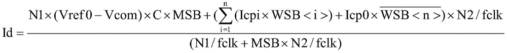
进一步的,步骤5中,计算公式为:Further, in
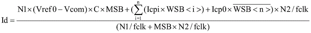
其中,Id为光电流大小,N1为强光预比较计数值,N2为数字化比较计数值,fclk为计数时钟脉冲的频率,Vref0为强光比较电压端输入的强光比较电压,Vcom为固定偏置电压输入端输入的固定偏置电压,C为积分电容的电容值,MSB为强光锁存器的输出值,WSB<1>~WSB<n>为各弱光锁存器的输出值,WSB<i>为第i个弱光锁存器的输出值,Icp0为非弱光补偿电流源的电流值,Icp1~Icpn为各弱光补偿电流源的电流值,其电流值由大至小进行排列,WSB<i>对应的弱光锁存器对应Icpi对应的弱光补偿电流源,n为弱光补偿电流源的数量,为大于等于1的整数。Among them, Id is the size of the photocurrent, N1 is the pre-comparison count value of the strong light, N2 is the digital comparison count value, fclk is the frequency of the counting clock pulse, Vref0 is the strong light comparison voltage input from the strong light comparison voltage terminal, and Vcom is the fixed bias. Set the fixed bias voltage input by the voltage input terminal, C is the capacitance value of the integral capacitor, MSB is the output value of the strong light latch, WSB<1>~WSB<n> is the output value of each weak light latch, WSB<i> is the output value of the ith weak light latch, Icp0 is the current value of the non-weak light compensation current source, Icp1~Icpn are the current values of each weak light compensation current source, and the current values are from large to small Arranged, the weak light latch corresponding to WSB<i> corresponds to the weak light compensation current source corresponding to Icpi, and n is the number of weak light compensation current sources, which is an integer greater than or equal to 1.
具体的,所述非弱光补偿电流源的电流值选择方法为:根据需要设定积分完成时间,记为Tmax并获取积分电容的电容值C或补偿电容的电容值C1,采用公式计算非弱光补偿电流源的最小值及各弱光补偿电流源的最小值;Specifically, the method for selecting the current value of the non-weak light compensation current source is as follows: set the integration completion time as required, record it as Tmax, obtain the capacitance value C of the integrating capacitor or the capacitance value C1 of the compensation capacitor, and use the formula to calculate the non-weak light compensation current value. The minimum value of the light compensation current source and the minimum value of each weak light compensation current source;
当应用于如权利要求8所述的高分辨率大动态范围数字化读出装置时,计算公式为:When applied to the digital readout device with high resolution and large dynamic range as claimed in claim 8, the calculation formula is:


当应用于如权利要求11所述的高分辨率大动态范围数字化读出装置时,计算公式为:When applied to the digital readout device with high resolution and large dynamic range as claimed in claim 11, the calculation formula is:
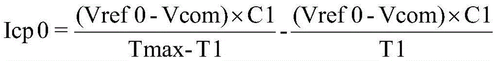
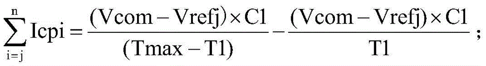
其中,Icpi是指第i个弱光补偿电流源的电流值,i为大于等于1小于等于n的整数,j为大于等于1小于等于n的整数,Icp1~Icpn为各弱光补偿电流源的电流值,其电流值由大至小进行排列,Vrefj是指第j个弱光比较电压的电压值,Vref1~Vrefn的电压值由大至小进行排列,Vrefj对应的弱光比较电压对应Icpj对应的弱光补偿电流源,T1为预比较阶段时间,Tmax为积分完成时间。Among them, Icpi refers to the current value of the i-th weak light compensation current source, i is an integer greater than or equal to 1 and less than or equal to n, j is an integer greater than or equal to 1 and less than or equal to n, and Icp1~Icpn are the values of each weak light compensation current source. Current value, the current value is arranged from large to small, Vrefj refers to the voltage value of the jth weak light comparison voltage, the voltage values of Vref1 ~ Vrefn are arranged from large to small, and the weak light comparison voltage corresponding to Vrefj corresponds to Icpj. The low-light compensation current source, T1 is the pre-comparison stage time, and Tmax is the integration completion time.
本发明的有益效果是,通过上述高分辨率大动态范围数字化读出装置及其读出方法,通过加入反向补偿电流源(包括非弱光补偿电流源及弱光补偿电流源),在积分过程中进行数字量化的方式,能够实现大动态范围高精度的数字化光强检测与数字量化,且在积分重置前实现光强的数字化;由于补偿电流存在,积分结束重置前总能触发常规比较器翻转,从而确保不同光强下的量化;动态范围及精度均与基础时钟信号频率有关,可通过适当增加基础时钟信号频率来扩大动态范围和探测精度,使得弱光强信号与强光信号探测的动态范围及精度均有提高。The beneficial effect of the present invention is that, through the above-mentioned digital readout device with high resolution and large dynamic range and the readout method thereof, by adding a reverse compensation current source (including a non-weak light compensation current source and a weak light compensation current source), in the integral The method of digital quantization in the process can realize digital light intensity detection and digital quantization with large dynamic range and high precision, and realize the digitization of light intensity before the integration reset; due to the existence of the compensation current, the routine can always be triggered before the reset is completed. The comparator is flipped to ensure quantization under different light intensities; the dynamic range and accuracy are related to the frequency of the basic clock signal, and the dynamic range and detection accuracy can be expanded by appropriately increasing the frequency of the basic clock signal, so that the weak light intensity signal and the strong light signal are The dynamic range and accuracy of detection are improved.
附图说明Description of drawings
图1为本发明实施例中高分辨率大动态范围数字化读出装置中弱光补偿电流源只有一个时的电路图;1 is a circuit diagram when there is only one low-light compensation current source in a high-resolution, large-dynamic-range digital readout device according to an embodiment of the present invention;
图2为本发明实施例中另一种高分辨率大动态范围数字化读出装置中弱光补偿电流源只有一个时的电路图;2 is a circuit diagram when there is only one low-light compensation current source in another high-resolution, large-dynamic-range digital readout device according to an embodiment of the present invention;
图3为图1中高分辨率大动态范围数字化读出装置的积分输出电压在不同光强下输出信号、固定控制时序及计数时钟信号示意图;3 is a schematic diagram of the integrated output voltage output signal, fixed control timing sequence and counting clock signal of the digital readout device with high resolution and large dynamic range under different light intensities in FIG. 1;
图4为图1中高分辨率大动态范围数字化读出装置在极强光信号且预比较剩余量较大情况下积分输出电压示意图及各逻辑控制开关时序图;4 is a schematic diagram of an integrated output voltage and a timing diagram of each logic control switch of the high-resolution, large-dynamic-range digital readout device in FIG. 1 under the condition of an extremely strong light signal and a large pre-comparison residual amount;
图5为图1中高分辨率大动态范围数字化读出装置在极强光信号且预比较剩余量极小情况下积分输出电压示意图及各逻辑控制开关时序图;5 is a schematic diagram of an integrated output voltage and a timing diagram of each logic control switch of the high-resolution, large-dynamic-range digital readout device in FIG. 1 under the condition of an extremely strong light signal and a very small pre-comparison residual;
图6为图1中高分辨率大动态范围数字化读出装置在较强光信号情况下积分输出电压示意图及各逻辑控制开关时序图。FIG. 6 is a schematic diagram of the integrated output voltage of the high-resolution, large-dynamic-range digital readout device in FIG. 1 and a timing diagram of each logic control switch in the case of a strong optical signal.
图7为图1中高分辨率大动态范围数字化读出装置在极弱光信号情况下积分输出电压示意图及各逻辑控制开关时序图。FIG. 7 is a schematic diagram of the integrated output voltage of the high-resolution, large-dynamic-range digital readout device in FIG. 1 and a timing diagram of each logic control switch in the case of a very weak light signal.
图8为图2中高分辨率大动态范围数字化读出装置中积分输出电压在不同光强下输出信号、固定控制时序及计数时钟信号示意图;8 is a schematic diagram of the output signal of the integrated output voltage, the fixed control sequence and the counting clock signal under different light intensities in the high-resolution and large dynamic range digital readout device in FIG. 2;
图9为图2中高分辨率大动态范围数字化读出装置在极强光信号且预比较剩余量较大情况下积分输出电压示意图及各逻辑控制开关时序图;9 is a schematic diagram of the integrated output voltage and a timing diagram of each logic control switch of the high-resolution and large dynamic range digital readout device in FIG. 2 under the condition of an extremely strong light signal and a large pre-comparison residual amount;
图10为图2中高分辨率大动态范围数字化读出装置在极强光信号且预比较剩余量极小情况下积分输出电压示意图及各逻辑控制开关时序图;10 is a schematic diagram of the integrated output voltage and a timing diagram of each logic control switch of the high-resolution, large-dynamic-range digital readout device in FIG. 2 under the condition of an extremely strong light signal and a very small pre-comparison residual;
图11为图2中高分辨率大动态范围数字化读出装置在较强光信号情况下积分输出电压示意图及各逻辑控制开关时序图。FIG. 11 is a schematic diagram of the integrated output voltage of the high-resolution, large-dynamic-range digital readout device in FIG. 2 and a timing diagram of each logic control switch in the case of a strong optical signal.
图12为图2中高分辨率大动态范围数字化读出装置在极弱光信号情况下积分输出电压示意图及各逻辑控制开关时序图。FIG. 12 is a schematic diagram of the integrated output voltage of the high-resolution, large-dynamic-range digital readout device in FIG. 2 and a timing diagram of each logic control switch in the case of a very weak light signal.
图13为本发明实施例中高分辨率大动态范围数字化读出装置的电路图;13 is a circuit diagram of a high-resolution, large-dynamic-range digital readout device according to an embodiment of the present invention;
图14为本发明实施例中另一种高分辨率大动态范围数字化读出装置的电路图;14 is a circuit diagram of another high-resolution and large-dynamic-range digital readout device according to an embodiment of the present invention;
其中,s1为外部复位控制信号,k1为复位控制开关一,k8为复位控制开关二,k2为强光控制开关,k3为常规控制开关,k4为弱光控制开关,s2为强光控制开关的控制端所输入的控制时序,s4为弱光控制开关k4的控制端所输入的控制时序,s3为外部控制信号,Vcom为固定偏置电压,C为积分电容,Det为光电转换器件,k9为补偿控制开关,s7为探测控制开关的控制端输入的时序,s5为非弱光补偿电流源对应的控制开关上控制端输入的时序,s6为弱光补偿电流源对应的控制开关上控制端输入的时序,counter1为强光计数器,counter2为常规计数器,Vref0为强光比较电压,Vref1~Vrefn为各弱光比较电压,Icp0为非弱光补偿电流源的电流值,Icp1~Icpn为各弱光补偿电流源的电流值,MSB为强光锁存器的输出值,WSB为弱光锁存器的输出值,WSB<1>~WSB<n>为各弱光锁存器的输出值,Count clk为计数时钟脉冲,Vsat,max为积分读出电路最大截止电压,Vsat,min为积分读出电路最小截止电压,Vout为积分输出电路的输出电压,T1为预比较阶段时间,Tmax为积分完成时间,T2为数字化阶段时间,Vd为预比较阶段积分读出电路的输出电压变化,V1为极强光环境下数字化阶段积分读出电路的输出电压变化,V2为较弱光环境下数字化阶段积分读出电路的输出电压变化,V3为极弱光环境下数字化阶段积分读出电路的输出电压变化,Vc1为应用在图2时常规比较器cmp2反向输入端电压的变化。Among them, s1 is the external reset control signal, k1 is the
具体实施方式Detailed ways
下面结合附图及实施例,详细描述本发明的技术方案。The technical solutions of the present invention will be described in detail below with reference to the accompanying drawings and embodiments.
本发明所述的高分辨率大动态范围数字化读出装置,包括探测电路、积分读出电路、数字化电路、总线输出电路、反向补偿电路及外部控制信号输入端,探测电路的输出端与积分读出电路的输入端连接,积分读出电路的输出端与数字化电路的输入端连接,数字化电路的输出端与总线输出电路连接,反向补偿电路包括输入端、输出端、一个非弱光补偿电流源及至少一个弱光补偿电流源,反向补偿电路的输入端与数字化电路的输出端连接,数字化电路的输出端还与探测电路的复位端连接,积分读出电路具有两个复位端,分别能够完成积分读出电路的复位,数字化电路的输出端还与积分读出电路的任意一个复位端连接,外部控制信号输入端分别与数字化电路及反向补偿电路连接;这里,探测电路用于转换光信号为电信号输出给积分读出电路,同时根据其复位端接收信号进行复位控制;积分读出电路用于对探测电路输入的电信号进行积分读出,读出的信号输出给数字化电路,同时根据其任意一个复位端的接收信号进行复位控制;数字化电路用于将积分读出电路读出的信号转换为数字化信号输出,并分别比较该读出的信号是否为强光信号及弱光信号,当判断是否为强光信号时,根据结果向与其连接的积分读出电路的复位端输出复位信号,且与外部控制信号输入端输入的外部控制信号一起控制探测电路的复位,当判断是否为弱光信号时,若为弱光信号,与通过外部控制信号输入端输入的外部控制信号一起控制反向补偿电路的对应弱光补偿电流源进行补偿,若为非弱光信号,与通过外部控制信号输入端输入的外部控制信号一起控制反向补偿电路的非弱光补偿电流源进行补偿;反向补偿电路的输出端与探测电路的输出端连接后与积分读出电路的输入端连接,或数字化电路还包括固定偏置电压输入端及补偿控制开关,固定偏置电压输入端通过补偿控制开关后与数字化电路的其余部分连接,反向补偿电路的输出端和补偿控制开关与数字化电路的其余部分连接的那一端连接,该补偿控制开关的控制端与积分读出电路中未与数字化电路连接的复位端受同样的外部复位控制信号控制。The high resolution and large dynamic range digital readout device of the present invention includes a detection circuit, an integral readout circuit, a digitization circuit, a bus output circuit, a reverse compensation circuit and an external control signal input end, the output end of the detection circuit and the integral The input end of the readout circuit is connected, the output end of the integral readout circuit is connected with the input end of the digitizing circuit, the output end of the digitizing circuit is connected with the bus output circuit, and the reverse compensation circuit includes an input end, an output end, a non-weak light compensation circuit The current source and at least one weak light compensation current source, the input end of the reverse compensation circuit is connected with the output end of the digitizing circuit, the output end of the digitizing circuit is also connected with the reset end of the detection circuit, and the integral readout circuit has two reset ends, The reset of the integral readout circuit can be completed respectively, the output end of the digitization circuit is also connected to any reset end of the integral readout circuit, and the input end of the external control signal is respectively connected to the digitization circuit and the reverse compensation circuit; here, the detection circuit is used for Convert the optical signal into an electrical signal and output it to the integration readout circuit, and at the same time perform reset control according to the signal received by its reset terminal; the integration readout circuit is used to integrate and read out the electrical signal input by the detection circuit, and the readout signal is output to the digitizing circuit. At the same time, the reset control is carried out according to the received signal of any of its reset terminals; the digital circuit is used to convert the signal read out by the integral readout circuit into a digital signal output, and respectively compare whether the readout signal is a strong light signal and a weak light signal. , when judging whether it is a strong light signal, output a reset signal to the reset terminal of the integrated readout circuit connected to it according to the result, and control the reset of the detection circuit together with the external control signal input from the external control signal input terminal. In the case of a weak light signal, if it is a weak light signal, it will control the corresponding weak light compensation current source of the reverse compensation circuit together with the external control signal input through the external control signal input terminal for compensation. The external control signal input from the signal input terminal controls the non-weak light compensation current source of the reverse compensation circuit to compensate; the output terminal of the reverse compensation circuit is connected to the output terminal of the detection circuit and then connected to the input terminal of the integration readout circuit, or The digitizing circuit also includes a fixed bias voltage input end and a compensation control switch, the fixed bias voltage input end is connected to the rest of the digitizing circuit after passing through the compensation control switch, and the output end of the reverse compensation circuit and the compensation control switch are connected with the rest of the digitizing circuit. The partially connected end is connected, and the control end of the compensation control switch and the reset end of the integral readout circuit that is not connected to the digitizing circuit are controlled by the same external reset control signal.
实施例Example
本发明实施例中的高分辨率大动态范围数字化读出装置,包括探测电路、积分读出电路、数字化电路、总线输出电路、反向补偿电路及外部控制信号输入端,探测电路的输出端与积分读出电路的输入端连接,积分读出电路的输出端与数字化电路的输入端连接,数字化电路的输出端与总线输出电路连接,反向补偿电路包括输入端、输出端、一个非弱光补偿电流源及至少一个弱光补偿电流源,反向补偿电路的输入端与数字化电路的输出端连接,数字化电路的输出端还与探测电路的复位端连接,积分读出电路具有两个复位端,分别能够完成积分读出电路的复位,数字化电路的输出端还与积分读出电路的任意一个复位端连接,外部控制信号输入端分别与数字化电路及反向补偿电路连接;反向补偿电路的输出端可与探测电路的输出端连接后与积分读出电路的输入端连接,其电路图参见图13;反向补偿电路的输出端还可以进行以下连接方式:数字化电路还包括固定偏置电压输入端及补偿控制开关,固定偏置电压输入端通过补偿控制开关k9后与数字化电路的其余部分连接,反向补偿电路的输出端和补偿控制开关k9与数字化电路的其余部分连接的那一端连接,该补偿控制开关k9的控制端与积分读出电路中未与数字化电路连接的复位端受同样的外部复位控制信号s1控制,其电路图参见图14。The high resolution and large dynamic range digital readout device in the embodiment of the present invention includes a detection circuit, an integral readout circuit, a digitization circuit, a bus output circuit, a reverse compensation circuit and an external control signal input end. The output end of the detection circuit is connected to an external control signal input end. The input end of the integral readout circuit is connected, the output end of the integral readout circuit is connected with the input end of the digitizing circuit, the output end of the digitizing circuit is connected with the bus output circuit, and the reverse compensation circuit includes an input end, an output end, a non-weak light The compensation current source and at least one weak light compensation current source, the input end of the reverse compensation circuit is connected with the output end of the digitizing circuit, the output end of the digitizing circuit is also connected with the reset end of the detection circuit, and the integral readout circuit has two reset ends , respectively can complete the reset of the integral readout circuit, the output end of the digitization circuit is also connected to any reset end of the integral readout circuit, and the input end of the external control signal is connected to the digitization circuit and the reverse compensation circuit respectively; The output terminal can be connected to the output terminal of the detection circuit and then connected to the input terminal of the integration readout circuit. The circuit diagram is shown in Figure 13; the output terminal of the reverse compensation circuit can also be connected in the following ways: the digitizing circuit also includes a fixed bias voltage input terminal and compensation control switch, the input terminal of the fixed bias voltage is connected to the rest of the digitizing circuit after passing through the compensation control switch k9, the output end of the reverse compensation circuit is connected to the end of the compensation control switch k9 that is connected to the rest of the digitizing circuit, The control terminal of the compensation control switch k9 and the reset terminal of the integral readout circuit that is not connected to the digitizing circuit are controlled by the same external reset control signal s1 , the circuit diagram of which is shown in FIG. 14 .
探测电路用于转换光信号为电信号输出给积分读出电路,同时根据其复位端接收信号进行复位控制。The detection circuit is used for converting the optical signal into an electrical signal and outputting it to the integral readout circuit, and at the same time performs reset control according to the signal received by the reset terminal.
本例中,探测电路可以包括光电转换器件Det及探测控制开关k7,光电转换器件Det的输出端通过探测控制开关k7后作为探测电路的输出端与积分读出电路连接,探测控制开关k7的控制端作为探测电路的复位端。In this example, the detection circuit may include a photoelectric conversion device Det and a detection control switch k7, and the output end of the photoelectric conversion device Det is connected to the integration readout circuit as the output end of the detection circuit through the detection control switch k7, and the control of the detection control switch k7 The terminal is used as the reset terminal of the detection circuit.
积分读出电路用于对探测电路输入的电信号进行积分读出,读出的信号输出给数字化电路,同时根据其任意一个复位端(k1或k8)的接收信号进行复位控制。The integral readout circuit is used for integral readout of the electrical signal input by the detection circuit, the readout signal is output to the digitization circuit, and at the same time, reset control is performed according to the received signal of any one of its reset terminals (k1 or k8).
本例中,为实现上述描述中的积分读出电路,则其包括复位控制开关一k1及复位控制开关二k8,复位控制开关一k1与复位控制开关二k8并联,复位控制开关一k1的控制端及复位控制开关二k8的控制端分别作为该积分读出电路的两个复位端,一个复位端(本例中,为复位开关二k8)与数字化电路的输出端连接,另一个复位端(本例中,为复位开关一k1)用于接受外部复位控制信号s1的控制;而积分读出电路本身可采用电容跨阻负反馈型读出电路或源随型读出电路或自积分读出电路或直接注入读出电路或缓冲直接注入读出电路等,均需包括积分电容C,当采用缓冲直接注入读出电路时,其结构可为:包括运算放大器、积分电容C、固定偏置电压输入端、复位控制开关一k1及复位控制开关二k8,运算放大器的正相输入端与固定偏置电压输入端连接,反相输入端与探测电路的输出端连接,积分电容C的一端与运算放大器的输出端连接,另一端与运算放大器的反相输入端连接,复位控制开关一k1及复位控制开关二k8分别与积分电容C并联,运算放大器的输出端作为积分读出电路的输出端。其中,复位控制开关一k1及复位控制开关二k8可以为PMOS开关或NMOS开关或CMOS开关或自举开关等。In this example, in order to realize the integral readout circuit in the above description, it includes a
数字化电路用于将积分读出电路读出的信号转换为数字化信号输出,并分别比较该读出的信号是否为强光信号及弱光信号,当判断是否为强光信号时,根据结果向与其连接的积分读出电路的复位端输出复位信号,且与外部控制信号输入端输入的外部控制信号S3一起控制探测电路的复位,当判断是否为弱光信号时,若为弱光信号,与通过外部控制信号输入端输入的外部控制信号S3一起控制反向补偿电路的对应弱光补偿电流源进行补偿,若为非弱光信号,与通过外部控制信号输入端输入的外部控制信号S3一起控制反向补偿电路的非弱光补偿电流源进行补偿。The digitizing circuit is used to convert the signal read out by the integral readout circuit into a digitized signal output, and compare whether the readout signal is a strong light signal and a weak light signal. The reset terminal of the connected integral readout circuit outputs a reset signal, and controls the reset of the detection circuit together with the external control signal S3 input from the external control signal input terminal. When judging whether it is a weak light signal, if it is a weak light signal, it will pass The external control signal S3 input from the external control signal input terminal controls the corresponding weak light compensation current source of the reverse compensation circuit for compensation. Compensate to the non-weak light compensation current source of the compensation circuit.
这里,当反向补偿电路的输出端与探测电路的输出端连接后与积分读出电路的输入端连接时,反向补偿电路的结构举例为:Here, when the output terminal of the reverse compensation circuit is connected to the output terminal of the detection circuit and then connected to the input terminal of the integral readout circuit, the structure of the reverse compensation circuit is as follows:
还包括一个非门、至少两个控制开关及至少两个与门,每一个与门与非弱光补偿电流源或一个弱光补偿电流源一一对应,且与一个控制开关一一对应,与非弱光补偿电流源对应的与门的一个输入端通过非门与数字化电路的输出端连接,其余每一个与门的一个输入端都直接与数字化电路的输出端连接,每一个与门的另一个输入端都与外部控制信号输入端连接,每一个与门的输出端都与对其对应的控制开关的控制端连接,非弱光补偿电流源及所有弱光补偿电流源的输出端分别通过与其对应的控制开关后连接在一起作为反向补偿电路的输出端。It also includes a NOT gate, at least two control switches and at least two AND gates, each AND gate corresponds to a non-weak light compensation current source or a low light compensation current source one-to-one, and corresponds to a control switch one-to-one, and One input end of the AND gate corresponding to the non-weak light compensation current source is connected with the output end of the digitizing circuit through the NOT gate, and one input end of each other AND gate is directly connected with the output end of the digitizing circuit, and the other end of each AND gate is directly connected with the output end of the digitizing circuit. One input terminal is connected to the input terminal of the external control signal, the output terminal of each AND gate is connected to the control terminal of the corresponding control switch, and the output terminals of the non-weak light compensation current source and all the low light compensation current sources pass through respectively. The corresponding control switch is connected together as the output terminal of the reverse compensation circuit.
则对应的数字化电路的结构举例为:包括外部清零信号输入端、与非门、强光控制开关k2、常规控制开关k3、强光比较电压输入端、固定偏置电压输入端、强光计数器counter1、常规计数器counter2、强光比较器、常规比较器、强光锁存器、至少一个弱光比较器、至少一个弱光比较电压输入端、至少一个弱光锁存器及至少一个弱光控制开关,所述一个弱光比较器分别与一个弱光比较电压输入端及一个弱光锁存器一一对应,强光比较器的正相输入端、常规比较器的正相输入端及所有弱光比较器的负相输入端连接后作为该数字化电路的输入端与积分读出电路的输出端连接,强光比较电压输入端与强光比较器的反相输入端连接,强光比较器的输出端通过强光控制开关k2后与积分读出电路的一个复位端连接,且与强光计数器counter1的输入端连接,强光计数器counter1的输出端分别与强光锁存器的输入端及总线输出电路连接,固定偏置电压输入端与常规比较器的反相输入端连接,常规比较器的输出端通过常规控制开关k3后与常规计数器counter2的输入端连接,常规计数器counter2的输出端与总线输出电路连接,每一个弱光比较器的正相输入端都和与其对应的弱光比较电压输入端连接,其输出端都和与其对应的弱光锁存器的输入端连接,强光锁存器的输出端还和与非门的一个输入端连接,与非门的另一个输入端与外部控制信号输入端连接,与非门的输出端与探测电路的复位端连接,一个弱光锁存器与一个弱光补偿电流源一一对应,每一个弱光锁存器的输出端都作为数字化电路的输出端分别和与其对应的弱光补偿电流源对应的与门的一个输入端一一对应连接,且各弱光补偿电流源中,至少其输出电流值最小的一个弱光补偿电流源对应的弱光锁存器的输出端作为数字化电路的输出端通过非门与非弱光补偿电流源对应的与门的一个输入端连接;其中,外部清零信号输入端用于接受外部复位控制信号s1的控制,分别与强光比较器的清零端、常规比较器的清零端、各弱光比较器的清零端、强光计数器counter1的清零端、常规计数器counter2的清零端、强光锁存器的清零端及各弱光锁存器的清零端连接;强光控制开关k2及所有弱光控制开关分别受不同的外部开关控制信号控制,常规控制开关k3受外部控制信号s3控制;常规计数器counter2的时钟端用于输入计数时钟脉冲count clk。强光锁存器及弱光锁存器均优选为1位锁存器。The corresponding digital circuit structure example is: including an external clear signal input terminal, a NAND gate, a strong light control switch k2, a conventional control switch k3, a strong light comparison voltage input terminal, a fixed bias voltage input terminal, and a strong light counter. counter1, conventional counter counter2, strong light comparator, normal comparator, strong light latch, at least one weak light comparator, at least one weak light comparison voltage input, at least one weak light latch and at least one weak light control switch, the one low-light comparator is in one-to-one correspondence with a low-light comparison voltage input terminal and a low-light latch, the positive-phase input terminal of the high-light comparator, the positive-phase input terminal of the conventional comparator and all The negative phase input terminal of the optical comparator is connected as the input terminal of the digitizing circuit and is connected to the output terminal of the integral readout circuit, and the strong light comparison voltage input terminal is connected with the inverting input terminal of the strong light comparator. The output end is connected to a reset end of the integral readout circuit through the strong light control switch k2, and is connected to the input end of the strong light counter counter1, and the output end of the strong light counter counter1 is respectively connected with the input end of the strong light latch and the bus line. The output circuit is connected, the fixed bias voltage input terminal is connected to the inverting input terminal of the conventional comparator, the output terminal of the conventional comparator is connected to the input terminal of the conventional counter counter2 after passing through the conventional control switch k3, and the output terminal of the conventional counter counter2 is connected to the bus The output circuit is connected, the non-inverting input end of each weak light comparator is connected with its corresponding weak light comparison voltage input end, and its output end is connected with the input end of its corresponding weak light latch, and the strong light latch The output end of the NAND gate is also connected to one input end of the NAND gate, the other input end of the NAND gate is connected to the input end of the external control signal, the output end of the NAND gate is connected to the reset end of the detection circuit, a weak light latch There is a one-to-one correspondence with a low-light compensation current source, and the output of each low-light latch is used as the output of the digital circuit to correspond to an input of the AND gate corresponding to the corresponding low-light compensation current source. connected, and among the weak light compensation current sources, at least the output end of the weak light compensation current source corresponding to the weak light compensation current source with the smallest output current value is used as the output end of the digital circuit through the NOT gate and the weak light compensation current source. One input end of the corresponding AND gate is connected; among them, the input end of the external clearing signal is used to accept the control of the external reset control signal s1, and is respectively connected with the clearing end of the strong light comparator, the clearing end of the conventional comparator, and the weak The clearing end of the optical comparator, the clearing end of the strong light counter counter1, the clearing end of the regular counter counter2, the clearing end of the strong light latch and the clearing end of each weak light latch are connected; strong light control The switch k2 and all the low light control switches are controlled by different external switch control signals respectively, the conventional control switch k3 is controlled by the external control signal s3; the clock terminal of the conventional counter counter2 is used to input the count clock pulse count clk. Both the strong light latch and the weak light latch are preferably 1-bit latches.
当数字化电路还包括常规比较电压输入端及补偿控制开关k9,常规比较电压输入端通过补偿控制开关k9后与数字化电路的其余部分连接,反向补偿电路的输出端和补偿控制开关k9与数字化电路的其余部分连接的那一端连接,该补偿控制开关的控制端与积分读出电路中未与数字化电路连接的复位端受同样的外部复位控制信号s1控制时,反向补偿电路的结构举例为:When the digitizing circuit further includes a conventional comparison voltage input terminal and a compensation control switch k9, the conventional comparison voltage input terminal is connected to the rest of the digitizing circuit through the compensation control switch k9, and the output terminal of the reverse compensation circuit and the compensation control switch k9 are connected with the digitizing circuit. When the control end of the compensation control switch and the reset end that is not connected to the digitizing circuit in the integral readout circuit are controlled by the same external reset control signal s1, the structure of the reverse compensation circuit is as follows:
还包括非门、电容C1、至少两个控制开关及至少两个与门,每一个与门与非弱光补偿电流源或一个弱光补偿电流源一一对应,且与一个控制开关一一对应,与非弱光补偿电流源对应的与门的一个输入端通过非门与数字化电路的输出端连接,其余每一个与门的一个输入端都直接与数字化电路的输出端连接,每一个与门的另一个输入端都与外部控制信号输入端连接,每一个与门的输出端都与对其对应的控制开关的控制端连接,非弱光补偿电流源及所有弱光补偿电流源的输出端分别通过与其对应的控制开关后连接在一起作为反向补偿电路的输出端,该输出端通过电容C1接地。It also includes a NOT gate, a capacitor C1, at least two control switches and at least two AND gates, each AND gate corresponds to a non-weak light compensation current source or a weak light compensation current source one-to-one, and corresponds to a control switch one-to-one , one input end of the AND gate corresponding to the non-weak light compensation current source is connected to the output end of the digitizing circuit through the NOT gate, and one input end of each other AND gate is directly connected to the output end of the digitizing circuit. The other input terminal of the AND gate is connected to the input terminal of the external control signal, the output terminal of each AND gate is connected to the control terminal of the corresponding control switch, the output terminals of the non-weak light compensation current source and all the low light compensation current sources They are respectively connected together through their corresponding control switches as the output ends of the reverse compensation circuit, and the output ends are grounded through the capacitor C1.
则对应的数字化电路的结构举例为:包括外部清零信号输入端、补偿控制开关k9、与非门、强光控制开关k2、常规控制开关k3、强光比较电压输入端、固定偏置电压输入端、强光计数器counter1、常规计数器counter2、强光比较器、常规比较器、强光锁存器、至少一个弱光比较器、至少一个弱光比较电压输入端、至少一个弱光锁存器及至少一个弱光控制开关,所述一个弱光比较器分别与一个弱光比较电压输入端及一个弱光锁存器一一对应,强光比较器的正相输入端、常规比较器的正相输入端及所有弱光比较器的负相输入端连接后作为该数字化电路的输入端与积分读出电路的输出端连接,强光比较电压输入端与强光比较器的反相输入端连接,强光比较器的输出端通过强光控制开关k2后与积分读出电路的一个复位端连接,且与强光计数器counter1的输入端连接,强光计数器counter1的输出端分别与强光锁存器的输入端及总线输出电路连接,固定偏置电压输入端通过补偿控制开关k9后与常规比较器的反相输入端连接,常规比较器的输出端通过常规控制开关k3后与常规计数器counter2的输入端连接,常规计数器counter2的输出端与总线输出电路连接,每一个弱光比较器的正相输入端都和与其对应的弱光比较电压输入端连接,其输出端都和与其对应的弱光锁存器的输入端连接,强光锁存器的输出端还和与非门的一个输入端连接,与非门的另一个输入端与外部控制信号输入端连接,与非门的输出端与探测电路的复位端连接,一个弱光锁存器与一个弱光补偿电流源一一对应,每一个弱光锁存器的输出端都作为数字化电路的输出端分别和与其对应的弱光补偿电流源对应的与门的一个输入端一一对应连接,且各弱光补偿电流源中,至少其输出电流值最小的一个弱光补偿电流源对应的弱光锁存器的输出端作为数字化电路的输出端通过非门与非弱光补偿电流源对应的与门的一个输入端连接;其中,外部清零信号输入端用于接受外部复位控制信号s1的控制,分别与强光比较器的清零端、常规比较器的清零端、各弱光比较器的清零端、强光计数器counter1的清零端、常规计数器counter2的清零端、强光锁存器的清零端及各弱光锁存器的清零端连接;强光控制开关k2及所有弱光控制开关分别受不同的外部开关控制信号控制,常规控制开关k3受外部控制信号控制;常规计数器counter2的时钟端用于输入计数时钟脉冲count clk。The corresponding digital circuit structure example is: including an external reset signal input terminal, a compensation control switch k9, a NAND gate, a strong light control switch k2, a conventional control switch k3, a strong light comparison voltage input terminal, and a fixed bias voltage input. terminal, strong light counter counter1, regular counter counter2, strong light comparator, regular comparator, strong light latch, at least one weak light comparator, at least one weak light comparison voltage input terminal, at least one weak light latch and At least one low-light control switch, the one low-light comparator is in one-to-one correspondence with a low-light comparison voltage input terminal and a low-light latch, the positive-phase input terminal of the high-light comparator, the positive-phase input terminal of the conventional comparator The input terminal and the negative-phase input terminals of all low-light comparators are connected as the input terminal of the digital circuit and connected to the output terminal of the integral readout circuit, and the high-light comparison voltage input terminal is connected with the inverting input terminal of the high-light comparator. The output end of the strong light comparator is connected to a reset end of the integral readout circuit through the strong light control switch k2, and is connected to the input end of the strong light counter counter1, and the output end of the strong light counter counter1 is respectively connected with the strong light latch. The input end of the constant bias voltage is connected to the bus output circuit, the fixed bias voltage input end is connected to the inverting input end of the conventional comparator after passing through the compensation control switch k9, and the output end of the conventional comparator is connected to the input end of the conventional counter counter2 after passing through the conventional control switch k3. The output terminal of the conventional counter counter2 is connected to the bus output circuit, the non-inverting input terminal of each low-light comparator is connected to its corresponding low-light comparison voltage input terminal, and its output terminal is connected to its corresponding low-light lock The input end of the register is connected, the output end of the strong light latch is also connected with one input end of the NAND gate, the other input end of the NAND gate is connected with the input end of the external control signal, and the output end of the NAND gate is connected with the detection The reset terminal of the circuit is connected, a weak light latch corresponds to a weak light compensation current source one by one, and the output end of each weak light latch is used as the output end of the digital circuit and its corresponding weak light compensation current source. One input end of the corresponding AND gate is connected in a one-to-one correspondence, and among the weak light compensation current sources, at least the output end of the weak light latch corresponding to the weak light compensation current source whose output current value is the smallest is used as the output of the digital circuit. The terminal is connected to an input terminal of the AND gate corresponding to the NOT gate and the non-weak light compensation current source; among them, the external clear signal input terminal is used to accept the control of the external reset control signal s1, and is respectively connected with the clear terminal of the strong light comparator. , the clear end of the conventional comparator, the clear end of each weak light comparator, the clear end of the strong light counter counter1, the clear end of the regular counter counter2, the clear end of the strong light latch and each weak light lock The clear terminal of the register is connected; the strong light control switch k2 and all the weak light control switches are controlled by different external switch control signals respectively, and the conventional control switch k3 is controlled by the external control signal; the clock terminal of the conventional counter counter2 is used to input the counting clock Pulse count clk.
本例中,控制开关可以为PMOS开关或NMOS开关或CMOS开关或自举开关等。强光锁存器及弱光锁存器均优选为1位锁存器。In this example, the control switch may be a PMOS switch, an NMOS switch, a CMOS switch, a bootstrap switch, or the like. Both the strong light latch and the weak light latch are preferably 1-bit latches.
本例中,总线输出电路可以包括强光预比较计数总线、数字化比较计数总线、强光判断总线及弱光判断总线,强光锁存器的输出端与强光判断总线连接,所有弱光锁存器的输出端都与弱光判断总线连接,强光计数器的输出端与强光预比较计数总线连接,常规计数器的输出端与数字化比较计数总线连接。In this example, the bus output circuit may include a strong light pre-comparison count bus, a digital comparison count bus, a strong light judgment bus, and a weak light judgment bus. The output end of the strong light latch is connected to the strong light judgment bus. All weak light locks The output end of the register is connected with the weak light judgment bus, the output end of the strong light counter is connected with the strong light pre-comparison counting bus, and the output end of the conventional counter is connected with the digital comparison counting bus.
根据上述举例中的结构,在使用时,包括以下步骤:According to the structure in the above example, when in use, the following steps are included:
步骤1、预比较阶段,外部控制信号为低电平,控制反向补偿电路的所有控制开关断开,探测电路的探测控制开关闭合,探测电路产生光电流信号在积分读出电路的积分电容上进行积分,外部开关控制信号控制强光控制开关闭合,强光比较器比较强光比较电压输入端输入的强光比较电压是否大于积分读出电路的输出电压,若是则其输出控制与其连接的积分读出电路的复位端不动作,且强光计数器不计数,否则其输出控制与其连接的积分读出电路的复位端复位,且强光计数器的计数值加1,当强光计数器的值为0时,强光锁存器此时为0,否则强光锁存器此时为1。
步骤2、预比较完成前至预比较完成阶段,该阶段时间为半个计数时钟脉冲周期,控制弱光控制开关闭合,若强光计数器的计数值为0,则强光锁存器锁存后输出为0,否则为1,同时各弱光比较器比较积分读出电路的输出电压是否大于对应弱光比较电压输入端输入的弱光比较电压,若是则该弱光比较器输出0经对应弱光锁存器锁存后输出为0,否则输出为1。
步骤3、数字化阶段,外部控制信号为高电平,常规控制开关闭合,当强光锁存器的输出为1时,探测电路的探测控制开关断开,不参与数字化阶段的积分;当强光锁存器的输出为0时,探测电路的探测控制开关闭合,进行数字化,探测电路输出的光电流信号参与积分,此时当所有弱光锁存器的输出为0时,与非弱光补偿电流源对应的控制开关闭合,而其余控制开关断开,非弱光补偿电流源进行反向补偿,当任意一个弱光锁存器的输出为1时,对应的控制开关闭合,而其余控制开关断开,对应的弱光补偿电流源进行反向补偿,同时常规计数器开始对计数时钟脉冲进行计数,当输入常规比较器正相输入端及反相输入端的电压大小翻转时停止计数,数字化阶段完成。
步骤4、总线输出阶段,数字化阶段完成时,总线输出电路获取强光预比较计数值、数字化比较计数值、强光判断值及弱光判断值,使其在积分完成前完成对光强的量化。
还可以包括以下步骤:The following steps can also be included:
步骤5、根据获取的强光预比较计数值、数字化比较计数值、强光判断值及弱光判断值计算得到光电流大小。Step 5: Calculate the photocurrent size according to the obtained strong light pre-comparison count value, digital comparison count value, strong light judgment value and weak light judgment value.
该计算公式为:The calculation formula is:
其中,Id为光电流大小,N1为强光预比较计数值,N2为数字化比较计数值,fclk为计数时钟脉冲的频率,Vref0为强光比较电压端输入的强光比较电压,Vcom为固定偏置电压输入端输入的固定偏置电压,C为积分电容的电容值,MSB为强光锁存器的输出值,WSB<1>~WSB<n>为各弱光锁存器的输出值,WSB<i>为第i个弱光锁存器的输出值,Icp0为非弱光补偿电流源的电流值,Icp1~Icpn为各弱光补偿电流源的电流值,其电流值由大至小进行排列,WSB<i>对应的弱光锁存器对应Icpi对应的弱光补偿电流源,n为弱光补偿电流源的数量,为大于等于1的整数。Among them, Id is the size of the photocurrent, N1 is the pre-comparison count value of the strong light, N2 is the digital comparison count value, fclk is the frequency of the counting clock pulse, Vref0 is the strong light comparison voltage input from the strong light comparison voltage terminal, and Vcom is the fixed bias. Set the fixed bias voltage input by the voltage input terminal, C is the capacitance value of the integral capacitor, MSB is the output value of the strong light latch, WSB<1>~WSB<n> is the output value of each weak light latch, WSB<i> is the output value of the ith weak light latch, Icp0 is the current value of the non-weak light compensation current source, Icp1~Icpn are the current values of each weak light compensation current source, and the current values are from large to small Arranged, the weak light latch corresponding to WSB<i> corresponds to the weak light compensation current source corresponding to Icpi, and n is the number of weak light compensation current sources, which is an integer greater than or equal to 1.
本例中,非弱光补偿电流源的电流值选择方法为:根据需要设定积分完成时间,记为Tmax并获取积分电容的电容值C或补偿电容的电容值C1,采用公式计算非弱光补偿电流源的最小值及各弱光补偿电流源的最小值;In this example, the selection method of the current value of the non-weak light compensation current source is: set the integration completion time as needed, record it as Tmax, and obtain the capacitance value C of the integrating capacitor or the capacitance value C1 of the compensation capacitor, and use the formula to calculate the non-weak light The minimum value of the compensation current source and the minimum value of each weak light compensation current source;
当应用于如图13所示的高分辨率大动态范围数字化读出装置时,计算公式为:When applied to the digital readout device with high resolution and large dynamic range as shown in Figure 13, the calculation formula is:


当应用于如图14所示的高分辨率大动态范围数字化读出装置时,计算公式为:When applied to the digital readout device with high resolution and large dynamic range as shown in Figure 14, the calculation formula is:


其中,Icpi是指第i个弱光补偿电流源的电流值,i为大于等于1小于等于n的整数,j为大于等于1小于等于n的整数,Icp1~Icpn为各弱光补偿电流源的电流值,其电流值由大至小进行排列,Icp0为非弱光补偿电流源的电流值,Vrefj是指第j个弱光比较电压的电压值,Vref1~Vrefn的电压值由大至小进行排列,Vrefj对应的弱光比较电压对应Icpj对应的弱光补偿电流源,Vref0为强光比较电压的电压值,T1为预比较阶段时间,Tmax为积分完成时间。Among them, Icpi refers to the current value of the i-th weak light compensation current source, i is an integer greater than or equal to 1 and less than or equal to n, j is an integer greater than or equal to 1 and less than or equal to n, and Icp1~Icpn are the values of each weak light compensation current source. Current value, the current value is arranged from large to small, Icp0 is the current value of the non-weak light compensation current source, Vrefj refers to the voltage value of the jth weak light comparison voltage, and the voltage values of Vref1~Vrefn are from large to small. Arrangement, the weak light comparison voltage corresponding to Vrefj corresponds to the weak light compensation current source corresponding to Icpj, Vref0 is the voltage value of the strong light comparison voltage, T1 is the pre-comparison stage time, and Tmax is the integration completion time.
本例中,Vref0较大,但小于运算放大器输出摆幅最大截止电压,即积分读出电路最大截止电压Vsat,max,Vref1~Vrefn较小,但大于固定偏置电压Vcom,Vref0大于Vref1~Vrefn。In this example, Vref0 is larger, but smaller than the maximum cut-off voltage of the output swing of the operational amplifier, that is, the maximum cut-off voltage V sat,max of the integral readout circuit, Vref1~Vrefn are smaller, but larger than the fixed bias voltage Vcom, and Vref0 is larger than Vref1~ Vrefn.
这里,以反向补偿电路只有一个弱光补偿电流源Icp1时分别进行具体举例:Here, specific examples are given when the reverse compensation circuit has only one weak light compensation current source Icp1:
参见图1,为反向补偿电路的输出端与探测电路的输出端连接后与积分读出电路的输入端连接时高分辨率大动态范围数字化读出装置的电路图;参见图2,为另一种高分辨率大动态范围数字化读出装置的电路图;参见图3,为图1中的电路计数时钟脉冲及各比较输出端口在不同光强背景下的输出信号;参见图8,为图2中的电路计数时钟脉冲及各比较输出端口在不同光强背景下的输出信号,图3及图8电路计数时钟脉冲相同,且相同光强背景下总线接收数据相同,Vcom为固定偏置电压,Vref0为强光比较器cmp1的强光比较电压,Vref1为弱光比较器cmp3的弱光比较电压,其中Vsat,min为积分读出电路最小截止电压,Vsat,max为积分读出电路最大截止电压,Tmax积分完成所需时间,T1为预比较时间,T2为数字化阶段时间。图3和图8中,Vd为预比较阶段积分读出电路的输出电压变化,V1为极强光环境下数字化阶段积分读出电路的输出电压变化,V2为较弱光环境下数字化阶段积分读出电路的输出电压变化,V3为极弱光环境下数字化阶段积分读出电路的输出电压变化,Vc1为应用在图2时常规比较器cmp2反向输入端电压的变化。s1为外部复位控制信号,同时各比较器(包括强光比较器、常规比较器及弱光比较器)、各计数器(包括强光计数器及常规计数器)及各锁存器(包括强光锁存器及弱光锁存器)的清理信号端也由s1控制,s2和s4时钟控制分别为极强光比较及极弱光比较提供控制时序,即分别为强光控制开关k2与弱光控制开关k4的控制端所输入的控制时序,使极强光量化检测仅在预比较阶段工作,极弱光比较判断在预比较结束前一个基础时钟周期(即半个计数时钟脉冲周期)工作,s3(即外部控制信号)为常规比较器cmp2提供控制时序,即为常规控制开关k3的控制端所输入的控制时序,使其仅在数字化阶段工作,控制开关k5(对应于非弱光补偿电流源Icp0的控制开关)、控制开关k6(对应于弱光补偿电流源Icp1的控制开关)及探测控制开关k7断开与闭合也与s3控制时序有关,s3提供的时序使反向补偿电流源(包括非弱光补偿电流源及弱光补偿电流源)仅在数字化阶段参与补偿,且保障探测的光电流在预比较阶段参与积分。Referring to FIG. 1, it is a circuit diagram of a high-resolution and large dynamic range digital readout device when the output end of the reverse compensation circuit is connected to the output end of the detection circuit and then connected to the input end of the integral readout circuit; A circuit diagram of a high-resolution, large-dynamic-range digital readout device; refer to FIG. 3, which is the circuit in FIG. 1 counting clock pulses and the output signals of each comparison output port under different light intensity backgrounds; refer to FIG. 8, which is the circuit in FIG. 2. The circuit count clock pulse and the output signal of each comparison output port under different light intensity backgrounds, the circuit count clock pulses in Figure 3 and Figure 8 are the same, and the bus receives the same data under the same light intensity background, Vcom is a fixed bias voltage, Vref0 is the strong light comparison voltage of the strong light comparator cmp1, Vref1 is the weak light comparison voltage of the weak light comparator cmp3, where V sat,min is the minimum cut-off voltage of the integral readout circuit, and V sat,max is the maximum cut-off of the integral readout circuit Voltage, the time required to complete the integration of Tmax, T1 is the pre-comparison time, and T2 is the digitization stage time. In Fig. 3 and Fig. 8, Vd is the output voltage change of the integral readout circuit in the pre-comparison stage, V1 is the output voltage change of the integral readout circuit in the digitization stage under the extremely strong light environment, and V2 is the integral readout in the digitization stage under the weak light environment. The output voltage of the output circuit changes, V3 is the output voltage change of the integral readout circuit in the digital stage in the extremely weak light environment, and Vc1 is the change of the reverse input terminal voltage of the conventional comparator cmp2 when applied in Figure 2. s1 is the external reset control signal, while each comparator (including strong light comparator, normal comparator and weak light comparator), each counter (including strong light counter and normal counter) and each latch (including strong light latch The clearing signal terminal of the light switch and the weak light latch) is also controlled by s1, and the clock control of s2 and s4 provides the control sequence for the extremely strong light comparison and the extremely weak light comparison respectively, that is, the strong light control switch k2 and the weak light control switch respectively. The control sequence input by the control terminal of k4 makes the extremely strong light quantization detection work only in the pre-comparison stage, and the extremely weak light comparison judgment works one basic clock cycle (that is, half a count clock pulse cycle) before the end of the pre-comparison, and s3 ( That is, the external control signal) provides the control sequence for the conventional comparator cmp2, which is the control sequence input by the control terminal of the conventional control switch k3, so that it only works in the digitization stage, and the control switch k5 (corresponding to the non-weak light compensation current source Icp0 The control switch), control switch k6 (corresponding to the control switch of the weak light compensation current source Icp1) and the opening and closing of the detection control switch k7 are also related to the control sequence of s3, and the sequence provided by s3 makes the reverse compensation current source (including non- The weak light compensation current source and the weak light compensation current source) only participate in the compensation in the digitization stage, and the detected photocurrent is guaranteed to participate in the integration in the pre-comparison stage.
按照图1所示的高分辨率大动态范围数字化读出装置,可在积分结束重置前数字化探测光强,具体情况及步骤如下:According to the high-resolution and large-dynamic-range digital readout device shown in Figure 1, the detection light intensity can be digitized before the reset is completed. The specific conditions and steps are as follows:
情况1、如图4所示,光强极强且预比较结束时电压剩余量较大。s1控制复位控制开关一k1重置完输出电压Vout后断开,此时探测控制开关k7闭合,光电转换器件Det产生的光电流进行积分,强光控制开关k2闭合,强光比较器cmp1工作,进入检测强光的预比较阶段。由于光强极强,光生电流在很短时间内使输出电压Vout积分到Vref0,此时强光比较器cmp1翻转使复位控制开关二k8重置,输出积分电压被重置到固定偏置电压Vcom,运算放大器输出翻转使复位控制开关二k8断开,积分读出电路继续积分,同时强光计数器counter1计数值加1,之后重复上述过程,当预比较阶段结束时,强光检测位MSB为1,探测控制开关k7断开,光电流暂时不参与积分,防止数字化阶段反向补偿电流比光电流小而补偿不足,预比较计数后电压剩余量仍然较大,弱光比较检测位WSB(由于仅有一个弱光补偿电流源Icp1,则仅有一个WSB<1>,此处简称WSB)为0,视光强为较强光信号,控制开关k5闭合,控制开关k6仍然断开,较大的非弱光补偿电流源Icp0进行反向补偿,同时常规控制开关k3闭合,常规比较器cmp2工作,常规计数器counter2开始计数,进入数字化阶段;由于仅有反向补偿电流(此时为Icp0)的作用,电压向下进行积分,经过T2时间后,积分读出电路的输出电压达到Vcom,常规比较器cmp2的输出翻转,常规计数器counter2停止计数,同时将计数值传入数字化比较计数总线;
情况2、如图5所示,光强极强且预比较结束时电压剩余量较小,s1控制复位控制开关一k1重置Vout后断开,探测控制开关k7闭合,光电转换器件Det产生光电流进行积分,强光控制开关k2闭合,强光比较器cmp1工作,进入预比较阶段。由于光强极强,光生电流在很短时间内使输出电压Vout积分到Vref0,此时强光比较器cmp1翻转使复位控制开关二k8重置,输出积分电压被重置到固定偏置电压Vcom,运算放大器输出翻转使复位控制开关二k8断开,积分读出电路继续积分,同时强光计数器counter1计数值加1,之后重复上述过程,当预比较阶段结束时,强光检测位MSB为1,探测控制开关k7断开,光电流暂时不参与积分,防止数字化阶段反向补偿电流比光电流小而补偿不足,因预比较计数后电压剩余量极小,弱光比较检测位WSB为1,视光强为极弱光信号,控制开关k6闭合,控制开关k5仍然断开,较小的弱光补偿电流源Icp1进行反向补偿,同时常规控制开关k3闭合,常规比较器cmp2工作,常规计数器counter2开始计数,进入数字化阶段,由于仅有反向补偿电流(此时为Icp1)的作用,电压向下进行积分,经过T2时间后,积分输出电压达到Vcom,常规比较器cmp2输出翻转,常规计数器counter2停止计数,同时将计数值传入数字化比较计数总线;
情况3、如图6所示,光强较强,预比较结束时电压积分量较大,s1控制复位控制开关一k1闭合重置Vout后断开,探测控制开关k7闭合,光电转换器件Det产生光电流进行积分,强光控制开关k2闭合,强光比较器cmp1工作,进入预比较阶段。由于光强较强,但光生电流在预比较结束时都未能使输出电压Vout积分到Vref0,预比较阶段强光比较器cmp1不翻转,复位控制开关二k8不闭合,强光计数器counter1计数值为0,预比较阶段结束时,强光检测位MSB为0,探测控制开关k7仍然闭合,光电流继续参与积分,因预比较阶段完成时,Vout>Vref1,弱光比较检测位WSB输出为0,视光强为较强光信号,控制开关k5闭合,控制开关k6仍然断开,采用较大的非弱光补偿电流源Icp0进行反向补偿,积分输出电压开始下降,同时常规控制开关k3闭合,常规比较器cmp2工作,常规计数器counter2开始计数,进入数字化阶段,电压Vout经过T2时间后,积分达到Vcom,常规比较器cmp2输出翻转,常规计数器counter2停止计数,同时将计数值传入数字化比较计数总线;
情况4、如图7所示,光强极弱,且预比较结束时电压积分量极小,s1控制复位控制开关一k1闭合重置Vout后断开,探测控制开关k7闭合,光电转换器件Det产生光电流进行积分,强光控制开关k2闭合,强光比较器cmp1工作,进入预比较阶段,由于光强极弱,光生电流在预比较结束时未能使输出电压Vout积分到Vref0,预比较阶段强光比较器cmp1不翻转,复位控制开关二k8不闭合,强光计数器counter1计数值为0,预比较阶段结束时,强光检测位MSB为0,探测控制开关k7仍然闭合,光电流继续参与积分,因预比较阶段完成时,Vout<Vref3,弱光比较检测位WSB为1,视光强为极弱光信号,控制开关k6闭合,控制开关k5仍然断开,采用较小的弱光补偿电流源Icp1进行反向补偿,同时常规控制开关k3闭合,常规比较器cmp2工作,常规计数器counter2开始计数,进入数字化阶段,输出电压Vout经过T2时间后积分达到Vcom,常规比较器cmp2输出翻转,常规计数器counter2停止计数,同时将计数值传入数字化比较计数总线;
按照图2所示的高分辨率大动态范围数字化读出装置,在积分结束重置前数字化探测光强,具体情况及步骤如下:According to the high-resolution and large-dynamic-range digital readout device shown in Figure 2, the light intensity is digitally detected before the integration is completed and reset. The specific conditions and steps are as follows:
情况1、如图9所示,光强极强且预比较结束时电压剩余量较大,s1控制复位控制开关一k1闭合重置Vout后断开,探测控制开关k7闭合,光电转换器件Det产生光电流进行积分,强光控制开关k2闭合,强光比较器cmp1工作,进入预比较阶段。由于光强极强,光生电流在很短时间内使输出电压Vout积分到Vref0,此时强光比较器cmp1翻转使复位控制开关二k8闭合,输出积分电压Vout被重置到Vcom,运算放大器输出翻转使复位控制开关二k8断开,积分读出电路继续积分,同时强光计数器counter1计数值加1,之后重复上述过程。预比较阶段结束时,强光检测位MSB为1,探测控制开关k7断开,光电流暂不进行积分,因预比较计数后电压剩余量仍然较大,弱光比较检测位WSB为0,视光强为较强光信号,控制开关k5闭合,控制开关k6仍然断开,采用较大的非弱光补偿电流源Icp0进行反向补偿,同时常规控制开关k3闭合,常规比较器cmp2工作,常规计数器counter2开始进行计数,进入数字化阶段,补偿电流在常规比较器cmp2输入端进行积分,经过T2时间后,该输入端电压超过Vout,常规比较器cmp2输出翻转,常规计数器counter2停止计数,同时将计数值传入数字化比较计数总线;
情况2、如图10所示,光强极强且预比较结束时电压剩余量较大,s1控制复位控制开关一k1闭合重置Vout后断开,探测控制开关k7闭合,光电转换器件Det产生光电流进行积分,强光控制开关k2闭合,强光比较器cmp1工作,进入预比较阶段,由于光强极强,光生电流在很短时间内使输出电压Vout积分到Vref0,此时强光比较器cmp1翻转使复位控制开关二k8闭合,输出积分电压Vout被重置到Vcom,运算放大器输出翻转使复位控制开关二k8断开,积分读出电路继续积分,同时强光计数器counter1计数值加1,之后重复上述过程。预比较阶段结束时,强光检测位MSB为1,探测控制开关k7断开,光电流暂不进行积分,因预比较计数后电压剩余量极小,弱光比较检测位WSB为1,视光强为极弱光信号,控制开关k6闭合,控制开关k5仍然断开,采用较小的弱光补偿电流源Icp1进行反向补偿,同时常规控制开关k3闭合,常规比较器cmp2工作,常规计数器counter2开始进行计数,进入数字化阶段,补偿电流在常规比较器cmp2输入端进行积分,经过T2时间后,该输入端电压超过Vout,常规比较器cmp2输出翻转,常规计数器counter2停止计数,同时将计数值传入数字化比较计数总线;
情况3、如图11所示,光强较强且预比较结束时电压积分量较大,s1控制复位控制开关一k1闭合重置Vout后断开,探测控制开关k7闭合,光电转换器件Det产生光电流进行积分,强光控制开关k2闭合,强光比较器cmp1工作,进入预比较阶段,由于光强较强,但光生电流在预比较结束时都未能使输出电压Vout积分到Vref0,预比较阶段强光比较器cmp1不翻转,复位控制开关二k8不闭合,强光计数器counter1计数值为0,当预比较阶段结束时,强光检测位MSB为0,探测控制开关k7仍然闭合,光电流继续积分,预比较阶段完成时,Vout>Vref1,弱光比较检测位WSB输出为0,视光强为较强光信号,控制开关k5闭合,控制开关k6仍然断开,采用较大的非弱光补偿电流源Icp0进行反向补偿,同时常规控制开关k3闭合,常规比较器cmp2工作,常规计数器counter2开始计数,进入数字化阶段,Icp0在常规比较器cmp2输入端进行积分,经过T2时间后,Vrefd>Vout,Vrefd为常规比较器cmp2的反相输入端输入的电压值,常规比较器cmp2输出翻转,常规计数器counter2停止计数,同时将计数值传入数字化比较计数总线;
情况4、如图12所示,光强极弱且预比较结束时电压积分量极小,s1控制复位控制开关一k1闭合重置Vout后断开,探测控制开关k7闭合,光电转换器件Det产生光电流进行积分,强光控制开关k2闭合,强光比较器cmp1工作,进入预比较阶段,由于光强极弱,光生电流在预比较结束时未能使输出电压Vout积分到Vref1,预比较阶段强光比较器cmp1不翻转,复位控制开关二k8不闭合,强光计数器counter1计数值为0,当预比较阶段结束时,强光检测位MSB为0,探测控制开关k7仍然闭合,光电流继续积分,预比较阶段完成时,Vout<Vref1,弱光比较检测位WSB为1,视光强为极弱光信号,控制开关k6闭合,控制开关k5仍然断开,采用较小的弱光补偿电流源Icp1进行反向补偿,同时常规控制开关k3闭合,常规比较器cmp2工作,常规计数器counter2开始计数,进入数字化阶段,Icp1在常规比较器cmp2输入端进行积分,经过T2时间后,Vrefd>Vout,Vrefd为常规比较器cmp2的反相输入端输入的电压值,常规比较器cmp2输出翻转,常规计数器counter2停止计数,同时将计数值传入数字化比较计数总线;
具体与现有的光强检测对比进行举例如下:The specific comparison with the existing light intensity detection is as follows:
传统的光强检测方法是在积分完成之后通过比较积分读出电路的积分电压或其模数转换结果来判断光照强弱。传统检测方法存在以下缺点:①传统的光强检测技术需要将积分电压进行模数转换,模数转换需要精确、复杂的电路,为了检测较弱的信号要求比较电路具有很高的精度,否则比较过程会因为被比较信号太弱而无法进行;②以自动调节曝光方式为代表的动态范围增强技术只能判断光照是否使像素饱和,不能检测出该光强的具体值。③以强光背景下多次比较重置,计算比较器翻转次数来提高动态范围的方式,只是在传统积分读出电路方式上增加了比较模块来提高强光探测范围,仍需要对剩余量进行数字化;④通常检测过程必须等待积分完成后才能开始,这就需要在积分或读出之后安排额外的比较时间,降低了电路读出的速度;The traditional light intensity detection method is to judge the light intensity by comparing the integral voltage of the integral readout circuit or its analog-to-digital conversion result after the integration is completed. The traditional detection method has the following shortcomings: 1. The traditional light intensity detection technology requires analog-to-digital conversion of the integrated voltage, and the analog-to-digital conversion requires an accurate and complex circuit. In order to detect weak signals, the comparison circuit is required to have high precision. The process cannot be carried out because the compared signal is too weak; ② The dynamic range enhancement technology represented by the automatic exposure adjustment method can only judge whether the light saturates the pixel, and cannot detect the specific value of the light intensity. ③ The method of comparing and resetting multiple times under the background of strong light, and calculating the number of times of comparator flips to improve the dynamic range, just adds a comparison module to the traditional integral readout circuit to improve the detection range of strong light, and the remaining amount still needs to be checked. Digitization; ④Usually the detection process must wait for the integration to complete before it can start, which requires additional comparison time to be arranged after integration or readout, which reduces the speed of circuit readout;
通过预比较阶段的极强光脉冲计数及极强光检测位的输出控制,预比较结束时极弱光的检测输出锁存控制,数字化阶段的反向补偿计数时钟脉冲计数,可在积分完成前对光生电流进行数字化处理;由于极强光信号和极弱光信号均进行了动态范围的扩充,使得像素单元动态范围有很大提升,且对极强光剩余量补偿处理和极弱光反向补偿电流选择的处理,使得探测精度非常精确。Through the extremely strong light pulse count in the pre-comparison stage and the output control of the extremely strong light detection bit, the detection output latch control of the extremely weak light at the end of the pre-comparison, and the reverse compensation count clock pulse count in the digitization stage, it can be counted before the integration is completed. The photo-generated current is digitally processed; since the dynamic range of the extremely strong light signal and the extremely weak light signal are expanded, the dynamic range of the pixel unit is greatly improved, and the residual amount of the extremely strong light is compensated for processing and extremely weak light reverse. The processing of compensation current selection makes the detection accuracy very precise.
总线输出电路接收强光预比较计数值、数字化比较计数值、强光判断值(强光检测位值MSB)及弱光判断值(弱光检测位值WSB),通过对这些值的直接计算即可得到光生电流大小。The bus output circuit receives the strong light pre-comparison count value, the digital comparison count value, the strong light judgment value (strong light detection bit value MSB) and the weak light judgment value (weak light detection bit value WSB). The magnitude of the photogenerated current can be obtained.
本例具体的光强检测方法如下:The specific light intensity detection method in this example is as follows:
根据输入共模范围及输出摆幅限制选取适当固定偏置电压Vcom、强光比较电压Vref0和弱光比较电压Vref1,根据电路需要设定积分完成时间为Tmax及积分电容C的值,由于补偿电流需在积分完成前使电压积分Vout达到Vcom,则在如图1的高分辨率大态动范围数字化读出装置中,所以所需补偿的非弱光补偿电流源的电流最小值为:Select the appropriate fixed bias voltage Vcom, strong light comparison voltage Vref0 and weak light comparison voltage Vref1 according to the input common mode range and output swing limit, and set the integration completion time as Tmax and the value of the integration capacitor C according to the needs of the circuit. It is necessary to make the voltage integration Vout reach Vcom before the integration is completed. In the high-resolution and large-dynamic-range digital readout device as shown in Figure 1, the minimum current of the non-weak light compensation current source that needs to be compensated is:

所需补偿的弱光补偿电流源的电流最小值为:The minimum current of the weak light compensation current source that needs to be compensated is:

则在如图2的高分辨率大态动范围数字化读出装置中,所以所需补偿的非弱光补偿电流源的电流最小值为:Then in the high-resolution and large-dynamic-range digital readout device as shown in Figure 2, the minimum current of the non-weak light compensation current source that needs to be compensated is:

所需补偿的弱光补偿电流源的电流最小值为:The minimum current of the weak light compensation current source that needs to be compensated is:

如图4或图9所示,极强光照且预比较结束时电压剩余量较大情况下,总线输出电路接收到强光计数器counter1计数为N1,MSB=1,常规计数器counter2在T1时间计数值为N1,在T2时间计数值为N2,WSB=0,此时As shown in Figure 4 or Figure 9, in the case of extremely strong light and the voltage remaining at the end of the pre-comparison is large, the bus output circuit receives the count value of the strong light counter counter1 as N1, MSB=1, and the conventional counter counter2 counts the value at the time T1 is N1, the count value at T2 time is N2, WSB=0, at this time
N1×(Vref0-Vcom)×C+Icp0×T2=Id×T1N1×(Vref0-Vcom)×C+Icp0×T2=Id×T1
如图5或图10所示,极强光照且预比较结束时电压剩余量较小情况下,总线输出电路接收到强光计数器counter1计数为N1,MSB=1,常规计数器counter2在T1时间计数值为N1,在T2时间计数值为N2,WSB=1,此时As shown in Figure 5 or Figure 10, in the case of extremely strong light and the voltage remaining at the end of the pre-comparison is small, the bus output circuit receives the count value of the strong light counter counter1 as N1, MSB=1, and the conventional counter counter2 counts the value at the time T1 is N1, the count value at T2 time is N2, WSB=1, at this time
N1×(Vref0-Vcom)×C+Icp1×T2=Id×T1N1×(Vref0-Vcom)×C+Icp1×T2=Id×T1
如图6或图11所示,较强光照在预比较结束时电压积分变换较大情况下,总线输出电路接收到强光计数器counter1计数为N1=0,MSB=0,常规计数器counter2在T1时间计数值为N1,在T2时间计数值为N2,WSB=0,此时As shown in Fig. 6 or Fig. 11, when the voltage integral transformation is large when the strong light is at the end of the pre-comparison, the bus output circuit receives that the strong light counter counter1 counts as N1 = 0, MSB = 0, and the regular counter counter2 is at the time T1. The count value is N1, the count value at T2 time is N2, WSB=0, at this time
Icp0×T2=Id×(T1+T2)Icp0×T2=Id×(T1+T2)
如图7或图12所示,极光光照在预比较结束时电压积分变化量极小条件,总线输出电路接收到强光计数器counter1计数为N1=0,MSB=0,常规计数器counter2在T1时间计数值为N1,在T2时间计数值为N2,WSB=1,此时As shown in Figure 7 or Figure 12, when the aurora light is at the end of the pre-comparison, the voltage integral change is extremely small, the bus output circuit receives the strong light counter counter1 counts as N1 = 0, MSB = 0, the conventional counter counter2 counts at T1 time The value is N1, the count value at T2 time is N2, WSB=1, at this time
Icp1×T2=Id×(T1+T2)Icp1×T2=Id×(T1+T2)
将MSB及WSB作为逻辑运算位,可将上述公式用如下公式表示:Taking MSB and WSB as logical operation bits, the above formula can be expressed by the following formula:


由上式求得探测电路光生电流为:From the above formula, the photogenerated current of the detection circuit can be obtained as:

由上式得出的探测电路光生电流大小可知,光生电流大小由四条总线所接收的计数值、检测位值、已知补偿电流和计数时钟脉冲的频率可计算出。It can be known from the photogenerated current of the detection circuit obtained from the above formula that the photogenerated current can be calculated from the count value received by the four buses, the detection bit value, the known compensation current and the frequency of the count clock pulse.
同理,可推断出当具有多个弱光补偿电流源时,在如图13的高分辨率大态动范围数字化读出装置中,所以所需补偿的非弱光补偿电流源的电流最小值为:In the same way, it can be inferred that when there are multiple low-light compensation current sources, in the high-resolution large dynamic range digital readout device as shown in Figure 13, the current minimum value of the non-low-light compensation current source that needs to be compensated for:

所需补偿的弱光补偿电流源的电流最小值为:The minimum current of the weak light compensation current source that needs to be compensated is:

则在如图2的高分辨率大态动范围数字化读出装置中,所以所需补偿的非弱光补偿电流源的电流最小值为:Then in the high-resolution and large-dynamic-range digital readout device as shown in Figure 2, the minimum current of the non-weak light compensation current source that needs to be compensated is:

所需补偿的弱光补偿电流源的电流最小值为:The minimum current of the weak light compensation current source that needs to be compensated is:

求得探测电路光生电流为:The photogenerated current of the detection circuit is obtained as:

与传统光强检测方法相比,本发明光强检测方法的优点在于:①本发明提出的光强检测装置及方法采用了反向电流补偿技术与数字化技术相结合,通过不同光强下积分电压到达同一个参考电压所需积分时间的不同,经数字化后得到光强检测结果,不需要生成多个参考电压,也不需要后续ADC处理积分电压电路;②预比较结束后光强检测过程与光电流积分及反向补偿过程同时进行,并先于积分过程完成,检测结果的读出和比较与像素读出也是同时进行的,没有改变读出电路原有的时序安排,不会影响阵列帧速;③在预比较阶段对极强光信号进行脉冲计数,对极弱光信号在数字化阶段选择较弱反向补偿电流,使得像素单元的动态范围有较大提高,且检测精度明显提高;④动态范围及探测精度都与计数时钟频率有关,适当调整时钟频率可使检测更准确;⑤预比较完成后,电压剩余量较小时被很快检测出,剩余时间可做其它行(或列)像素单元光强检测等。Compared with the traditional light intensity detection method, the advantages of the light intensity detection method of the present invention are: ① the light intensity detection device and method proposed by the present invention adopts the combination of reverse current compensation technology and digital technology, and integrates the voltage under different light intensities. The integration time required to reach the same reference voltage is different, and the light intensity detection result is obtained after digitization, and there is no need to generate multiple reference voltages, nor to process the integrated voltage circuit by subsequent ADC; ② After the pre-comparison, the light intensity detection process is related to the light The current integration and reverse compensation processes are carried out at the same time and are completed before the integration process. The readout and comparison of the detection results and the pixel readout are also carried out at the same time. The original timing arrangement of the readout circuit is not changed, and the frame rate of the array will not be affected. 3. In the pre-comparison stage, the pulse count is performed for the extremely strong light signal, and the weaker reverse compensation current is selected in the digitization stage for the extremely weak light signal, so that the dynamic range of the pixel unit is greatly improved, and the detection accuracy is significantly improved; ④ Dynamic The range and detection accuracy are related to the counting clock frequency. Proper adjustment of the clock frequency can make the detection more accurate; ⑤After the pre-comparison is completed, the voltage remaining is detected quickly when the remaining voltage is small, and the remaining time can be used for other row (or column) pixel units Light intensity detection, etc.
且根据上述描述可知,还可更换各弱光比较器的正相输入端及反相输入端的连接关系,更换后则需要在与弱光补偿电流源对应的与门的输入端加入相应的非门,而去掉非弱光补偿电流源对应的与门的输入端上的非门,计算公式进行相应修改即可。And according to the above description, the connection relationship between the non-inverting input terminal and the inverting input terminal of each low-light comparator can also be replaced. After replacement, a corresponding NOT gate needs to be added to the input terminal of the AND gate corresponding to the low-light compensation current source. , and remove the NOT gate on the input end of the AND gate corresponding to the non-weak light compensation current source, and modify the calculation formula accordingly.
综上所述,本发明能在像素内完成对积分电压的完全数字量化,且在积分完成前即可准确地检测光照强度,通过对极强光的预比较阶段的脉冲计数,及对极弱光信号选择不同的补偿电流,明显提高像素的动态范围及探测精度。To sum up, the present invention can complete the digital quantization of the integrated voltage in the pixel, and can accurately detect the light intensity before the integration is completed. Different compensation currents are selected for the optical signal, which significantly improves the dynamic range and detection accuracy of the pixel.
Claims (16)


Priority Applications (1)
| Application Number | Priority Date | Filing Date | Title |
|---|---|---|---|
| CN201710743804.4A CN107613230B (en) | 2017-08-25 | 2017-08-25 | High resolution and large dynamic range digital readout device and readout method thereof |
Applications Claiming Priority (1)
| Application Number | Priority Date | Filing Date | Title |
|---|---|---|---|
| CN201710743804.4A CN107613230B (en) | 2017-08-25 | 2017-08-25 | High resolution and large dynamic range digital readout device and readout method thereof |
Publications (2)
| Publication Number | Publication Date |
|---|---|
| CN107613230A CN107613230A (en) | 2018-01-19 |
| CN107613230B true CN107613230B (en) | 2020-06-09 |
Family
ID=61055767
Family Applications (1)
| Application Number | Title | Priority Date | Filing Date |
|---|---|---|---|
| CN201710743804.4A Expired - Fee Related CN107613230B (en) | 2017-08-25 | 2017-08-25 | High resolution and large dynamic range digital readout device and readout method thereof |
Country Status (1)
| Country | Link |
|---|---|
| CN (1) | CN107613230B (en) |
Families Citing this family (5)
| Publication number | Priority date | Publication date | Assignee | Title |
|---|---|---|---|---|
| CN108848326B (en) * | 2018-06-13 | 2021-01-01 | 吉林大学 | Front-end reading circuit of high dynamic range MCP detector and reading method thereof |
| WO2020042189A1 (en) * | 2018-08-31 | 2020-03-05 | 深圳市大疆创新科技有限公司 | Pixel unit, image sensor and operation method therefor, and camera device |
| TWI770918B (en) * | 2021-03-31 | 2022-07-11 | 新唐科技股份有限公司 | Set value auto-adjusting device and method thereof |
| CN113194272B (en) * | 2021-04-28 | 2022-05-20 | 电子科技大学 | Large dynamic range reading circuit for photoelectric detector |
| CN116470889B (en) * | 2023-04-10 | 2024-04-16 | 北京大学 | Comparator circuit, analog-digital converter and electronic equipment |
Citations (4)
| Publication number | Priority date | Publication date | Assignee | Title |
|---|---|---|---|---|
| CN101514922A (en) * | 2009-03-11 | 2009-08-26 | 东南大学 | Linearity high dynamic range infrared reading circuit |
| CN102752560A (en) * | 2012-06-21 | 2012-10-24 | 吉林大学 | Ultra-wide dynamic range image sensor based on pixel charge compensation technology |
| CN103323111A (en) * | 2013-06-07 | 2013-09-25 | 华南理工大学 | Pre-amplification and measuring range automatic switching circuit for light intensity detection |
| CN104539857A (en) * | 2014-12-26 | 2015-04-22 | 电子科技大学 | Light current reading circuit and self-adaption light intensity imaging array circuit and control method thereof |
Family Cites Families (2)
| Publication number | Priority date | Publication date | Assignee | Title |
|---|---|---|---|---|
| US8410416B2 (en) * | 2010-04-29 | 2013-04-02 | King Abdulaziz City For Science And Technology | Reduction of delay between subsequent capture operations of a light-detection device |
| US10203400B2 (en) * | 2015-07-31 | 2019-02-12 | Avago Technologies International Sales Pte. Limited | Optical measurement system incorporating ambient light component nullification |
-
2017
- 2017-08-25 CN CN201710743804.4A patent/CN107613230B/en not_active Expired - Fee Related
Patent Citations (4)
| Publication number | Priority date | Publication date | Assignee | Title |
|---|---|---|---|---|
| CN101514922A (en) * | 2009-03-11 | 2009-08-26 | 东南大学 | Linearity high dynamic range infrared reading circuit |
| CN102752560A (en) * | 2012-06-21 | 2012-10-24 | 吉林大学 | Ultra-wide dynamic range image sensor based on pixel charge compensation technology |
| CN103323111A (en) * | 2013-06-07 | 2013-09-25 | 华南理工大学 | Pre-amplification and measuring range automatic switching circuit for light intensity detection |
| CN104539857A (en) * | 2014-12-26 | 2015-04-22 | 电子科技大学 | Light current reading circuit and self-adaption light intensity imaging array circuit and control method thereof |
Non-Patent Citations (1)
| Title |
|---|
| 像素级数字化紫外焦平面读出电路的研究;徐斌 等;《半导体光电》;20141031;第35卷(第5期);第768-772,806页 * |
Also Published As
| Publication number | Publication date |
|---|---|
| CN107613230A (en) | 2018-01-19 |
Similar Documents
| Publication | Publication Date | Title |
|---|---|---|
| CN107613230B (en) | High resolution and large dynamic range digital readout device and readout method thereof | |
| CN107888850B (en) | Imaging system and apparatus and method for providing increased analog-to-digital conversion range | |
| CN111698439B (en) | Integrating ramp circuit with reduced ramp settling time | |
| CN203775318U (en) | Ultraviolet focal plane readout circuit based on pixel-level analog-to-digital conversion | |
| US8933385B2 (en) | Hybrid analog-to-digital converter having multiple ADC modes | |
| CN104539857B (en) | Photoelectric current reading circuit and adaptive light intensity imaging array circuit and its control method | |
| CN103856730A (en) | Ultraviolet focal plane readout circuit and method based on pixel level analog-to-digital conversion | |
| WO2018140012A1 (en) | Imaging array with extended dynamic range | |
| CN114650382B (en) | Comparator stage with DC cut-off for single slope analog-to-digital converter | |
| CN107396009B (en) | Pulse frequency modulation type image sensor circuit and processing method thereof | |
| US10128866B2 (en) | Fast current mode sigma-delta analog-to-digital converter | |
| CN107925735B (en) | Image processing circuits and imaging devices | |
| US11196949B2 (en) | Subrange ADC for image sensor | |
| CN117479034A (en) | Low power event driven pixels with passive differential detection circuitry and reset control circuits therefor | |
| CN112954237A (en) | Self-adaptive variable gain integrating circuit for photoelectric detector | |
| US11991465B2 (en) | Low power event driven pixels with passive, differential difference detection circuitry, and reset control circuits for the same | |
| CN108600579B (en) | Motion detection circuit and motion detection method applied to CIS | |
| CN107515050B (en) | A kind of infrared focal plane read-out circuit | |
| CN101876570A (en) | A Readout Integrated Circuit with Automatic Blind Cell Rejection Function | |
| CN102252759A (en) | Infrared focal plane readout integrated circuit with digital output | |
| CN104767526A (en) | A Comparator Applied in Digital Readout Circuit of Infrared Focal Plane Array | |
| CN112180422A (en) | Preamplifier, Pixel Cell Circuit, and Pixel Array Detector | |
| CN116915255B (en) | Calibration circuit for ramp stabilization auxiliary circuit in local ramp buffer circuit | |
| CN105554421B (en) | global pixel nonlinear compensation structure | |
| Zhong et al. | A 6.25-M-pixel 270-fps floating gate image sensor using high-speed and low-power readout technology |
Legal Events
| Date | Code | Title | Description |
|---|---|---|---|
| PB01 | Publication | ||
| PB01 | Publication | ||
| SE01 | Entry into force of request for substantive examination | ||
| SE01 | Entry into force of request for substantive examination | ||
| GR01 | Patent grant | ||
| GR01 | Patent grant | ||
| CF01 | Termination of patent right due to non-payment of annual fee |
Granted publication date: 20200609 |
|
| CF01 | Termination of patent right due to non-payment of annual fee |