CN107547458B - Method, device and remote radio unit for setting image suppression parameters in IQ modulation - Google Patents
Method, device and remote radio unit for setting image suppression parameters in IQ modulation Download PDFInfo
- Publication number
- CN107547458B CN107547458B CN201610482310.0A CN201610482310A CN107547458B CN 107547458 B CN107547458 B CN 107547458B CN 201610482310 A CN201610482310 A CN 201610482310A CN 107547458 B CN107547458 B CN 107547458B
- Authority
- CN
- China
- Prior art keywords
- adjustment value
- modulator
- signal
- amplitude
- channel component
- Prior art date
- Legal status (The legal status is an assumption and is not a legal conclusion. Google has not performed a legal analysis and makes no representation as to the accuracy of the status listed.)
- Active
Links
Images


Landscapes
- Digital Transmission Methods That Use Modulated Carrier Waves (AREA)
Abstract
本发明公开了一种IQ调制中镜像抑制参数的设置方法、装置及射频拉远单元。其中方法包括:预设IQ调制器的IQ信号的相位偏移


The invention discloses a method, a device and a radio frequency remote unit for setting image suppression parameters in IQ modulation. The method includes: presetting the phase offset of the IQ signal of the IQ modulator
Description
Technical Field
The present invention relates to the field of wireless communication technologies, and In particular, to a method and an apparatus for setting image suppression parameters In IQ (In-phase Quadrature) modulation, and a radio remote unit.
Background
Conventionally, a baseband signal is generally up-converted to a Radio frequency signal in a Remote Radio Unit (RRU), and then the Radio frequency signal is transmitted to an antenna, so as to wirelessly transmit the Radio frequency signal by using the antenna. In the process of up-converting a baseband signal into a radio frequency signal, IQ modulation needs to be performed on the baseband signal, that is, an I component and a Q component in the IQ signal are respectively modulated by using a local oscillation signal (local oscillation signal for short). However, the modulated IQ signal generally contains an image signal, which is mainly caused by the phase and amplitude imbalance between the local oscillation signal and the IQ signal. In order to suppress the image signal, it is a conventional practice to perform certain phase and amplitude processing on the IQ signal before IQ modulation, so that the modulated IQ signal can suppress the image signal. In general, predetermined phase adjustment parameters and predetermined amplitude adjustment parameters are used to adjust the phase and amplitude of the IQ signals, which requires the predetermined adjustment parameters. However, in the conventional method, when determining the phase adjustment parameter and the amplitude adjustment parameter, the power of the leakage signal needs to be tested repeatedly (for example, the number of tests may reach more than 30) under different adjustment parameters, and then the appropriate phase adjustment parameter and amplitude adjustment parameter can be determined. Therefore, the prior art needs to improve the complexity of determining the phase adjustment parameter and the amplitude adjustment parameter.
Disclosure of Invention
The technical problem to be solved by the embodiments of the present invention is to provide a method and an apparatus for setting mirror image suppression parameters in IQ modulation, and a radio remote unit, so as to reduce the complexity in determining the mirror image suppression parameters.
To solve the above technical problem, an embodiment of the present invention provides a method for setting mirror image suppression parameters in IQ modulation, including: presetting the phase offset of IQ signal of IQ modulator And
And and is obtained at
 And
And the power P of the mirror leakage signal of the IQ modulator1And P2(ii) a Presetting a normalized amplitude ratio G between an I-path component and a Q-path component in an IQ signal of the IQ modulator1And G2And is obtained at G1And G2The power P of the mirror leakage signal of the IQ modulator3And P4(ii) a Acquisition is based on
 P1And P2Obtaining a phase adjustment value in the image rejection parameter; acquisition is based on this G1、G2、P3And P4Obtaining a first amplitude adjustment value in the image rejection parameter, and obtaining a second amplitude adjustment value in the image rejection parameter which is a preset value; and setting the phase adjustment value, the first amplitude adjustment value and the second amplitude adjustment value into an analog-to-digital converter (DAC), wherein the DAC is a front-end circuit of the IQ modulator.
Wherein the obtaining is based on P1And P2To obtain the mirror imageSuppressing phase adjustment values in the parameters, comprising: acquisition is based on
 P1And P2Obtaining the quadrature phase error between the I path component and the Q path component of the local oscillation signal used in the in-phase quadrature IQ modulator; the phase adjustment value obtained based on a quadrature phase error between an I-path component and a Q-path component of the local oscillation signal is acquired.
Wherein the obtaining is based on P1And P2The obtained quadrature phase error between the I-path component and the Q-path component of the local oscillation signal used in the in-phase quadrature IQ modulator comprises: the acquisition is based on the formula:
 and the quadrature phase error theta between the I-path component and the Q-path component of the local oscillation signal is obtained.
Wherein the obtaining the phase adjustment value obtained based on a quadrature phase error between an I-path component and a Q-path component of the local oscillation signal comprises: obtaining according to the formula: the resulting phase adjustment value qmc _ phaseAB, where,
 is a quadrature phase error between an I-path component and a Q-path component of an IQ signal supplied to the IQ modulator, and
 equal to the quadrature phase error between the I and Q components, where qmc _ phaseAB is the phase adjustment value.
Wherein the quadrature phase error comprises: a first quadrature phase error and a second quadrature phase error; the obtaining the phase adjustment value obtained based on the quadrature phase error between the I-path component and the Q-path component of the local oscillation signal includes: obtaining a first phase adjustment value and a second phase adjustment value which are obtained respectively based on the first quadrature phase error and the second quadrature phase error; acquiring a first leakage power value and a second leakage power value of the mirror image leakage signal of the IQ modulator corresponding to the first phase adjustment value and the second phase adjustment value; and acquiring a phase adjustment value corresponding to the smaller one of the first leakage power value and the second leakage power value, and taking the phase adjustment value as the phase adjustment value finally set to the DAC.
Wherein the obtaining is based on the G1、G2、P3And P4And obtaining a first amplitude adjustment value in the image rejection parameter, including: acquisition is based on this G1、G2、P3And P4Obtaining the normalized amplitude ratio between the I-path component and the Q-path component of the local oscillation signal used in the IQ modulator; the first amplitude adjustment value obtained based on a normalized amplitude ratio between an I-path component and a Q-path component of the local oscillation signal is obtained.
Wherein the obtaining is based on the G1、G2、P3And P4The obtained normalized amplitude ratio between the I-path component and the Q-path component of the local oscillation signal used in the IQ modulator comprises: the acquisition is based on the formula: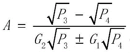 and obtaining the normalized amplitude ratio A between the I-path component and the Q-path component of the local oscillation signal.
Wherein the obtaining the first amplitude adjustment value obtained based on the normalized amplitude ratio between the I-path component and the Q-path component of the local oscillation signal includes: the acquisition is based on the formula: qmc _ gainA is a · 1024, and the first amplitude adjustment value qmc _ gainA is obtained.
Wherein the normalized amplitude ratio between the I-path component and the Q-path component of the local oscillation signal comprises: a first normalized amplitude ratio and a second normalized amplitude ratio; respectively obtaining a third amplitude adjustment value and a fourth amplitude adjustment value corresponding to the first normalized amplitude ratio and the second normalized amplitude ratio; respectively acquiring a first leakage power value and a second leakage power value of the mirror image leakage signal in the IQ modulator corresponding to the third amplitude adjustment value and the fourth amplitude adjustment value; a corresponding amplitude adjustment value for the lesser of the first and second leakage power values is obtained and is used as the first amplitude adjustment value that is ultimately set to the DAC.
Wherein the preset value is 1024.
An embodiment of the present invention further provides a setting apparatus, configured to set a mirror image suppression parameter used in IQ modulation, including: a first processing module for presetting the phase offset of IQ signal of IQ modulator And
And and is obtained at
 And
And the power P of the mirror leakage signal of the IQ modulator1And P2(ii) a A second processing module for presetting a normalized amplitude ratio G between the I-path component and the Q-path component in the IQ signal of the IQ modulator1And G2And is obtained at G1And G2The power P of the mirror leakage signal of the IQ modulator3And P4(ii) a And a third processing module for obtaining a data stream based on the data stream
 P1And P2Obtaining a phase adjustment value in the image rejection parameter; a fourth processing module for obtaining a signal based on the G1、G2、P3And P4Obtaining a first amplitude adjustment value in the image rejection parameter, and obtaining the image with a preset valueA second amplitude adjustment value in the suppression parameter; and a setting module, configured to set the phase adjustment value, the first amplitude adjustment value, and the second amplitude adjustment value to a DAC, where the DAC is a front-end circuit of the IQ modulator.
The third processing module is specifically configured to: a first obtaining unit for obtaining the data based on the P1And P2Obtaining the quadrature phase error between the I path component and the Q path component of the local oscillation signal used in the in-phase quadrature IQ modulator; and a second acquisition unit configured to acquire the phase adjustment value obtained based on a quadrature phase error between the I-path component and the Q-path component of the local oscillation signal.
The first obtaining unit is specifically configured to obtain, according to a formula: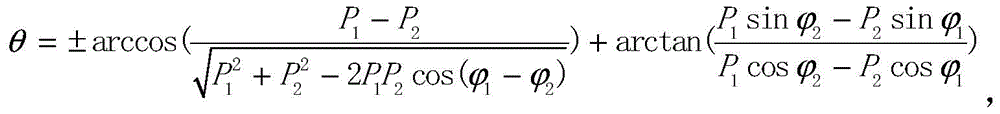 and the quadrature phase error theta between the I-path component and the Q-path component of the local oscillation signal is obtained.
The second obtaining unit is specifically configured to obtain, according to a formula: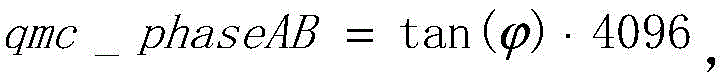 the resulting phase adjustment value qmc _ phaseAB, where,
 is a quadrature phase error between an I-path component and a Q-path component of an IQ signal supplied to the IQ modulator, and
 equal to the quadrature phase error between the I and Q components.
Wherein the quadrature phase error comprises: a first quadrature phase error and a second quadrature phase error; the second obtaining unit is specifically configured to: obtaining a first phase adjustment value and a second phase adjustment value which are obtained respectively based on the first quadrature phase error and the second quadrature phase error; acquiring a first leakage power value and a second leakage power value of the mirror image leakage signal of the IQ modulator corresponding to the first phase adjustment value and the second phase adjustment value; and acquiring a phase adjustment value corresponding to the smaller one of the first leakage power value and the second leakage power value, and taking the phase adjustment value as the phase adjustment value finally set to the DAC.
Wherein, the fourth processing module comprises: a third acquisition unit for acquiring the data based on the G1、G2、P3And P4Obtaining the normalized amplitude ratio between the I-path component and the Q-path component of the local oscillation signal used in the IQ modulator; and a fourth acquisition unit configured to acquire the first amplitude adjustment value obtained based on a normalized amplitude ratio between the I-path component and the Q-path component of the local oscillation signal.
The third obtaining unit is specifically configured to obtain a formula-based: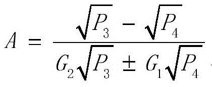 and obtaining the normalized amplitude ratio A between the I-path component and the Q-path component of the local oscillation signal.
The fourth obtaining unit is specifically configured to obtain a formula-based: qmc _ gainA is a · 1024, and the first amplitude adjustment value qmc _ gainA is obtained.
Wherein the normalized amplitude ratio between the I-path component and the Q-path component of the local oscillation signal comprises: a first normalized amplitude ratio and a second normalized amplitude ratio; the fourth obtaining unit is specifically configured to: respectively obtaining a third amplitude adjustment value and a fourth amplitude adjustment value corresponding to the first normalized amplitude ratio and the second normalized amplitude ratio; respectively acquiring a first leakage power value and a second leakage power value of the mirror image leakage signal in the IQ modulator corresponding to the third amplitude adjustment value and the fourth amplitude adjustment value; a corresponding amplitude adjustment value for the lesser of the first and second leakage power values is obtained and is used as the first amplitude adjustment value that is ultimately set to the DAC.
An embodiment of the present invention further provides a remote radio unit, including: the digital-to-analog converter comprises an IQ modulator, a DAC and the setting device, wherein the DAC is connected with the IQ modulator and is used for transmitting a baseband signal to the IQ modulator for IQ modulation after the baseband signal is processed; wherein, this DAC includes: the phase adjustment register, the first gain adjustment register and the second gain adjustment register; and the setting device is used for setting the phase adjustment value of the phase adjustment register, the first amplitude adjustment value of the first gain adjustment register and the second amplitude adjustment value of the second gain adjustment register.
The invention has the beneficial effects that:
the method, the apparatus and the remote radio unit utilize the predetermined phase offset of the IQ signal of the IQ modulator And
And and the power of its corresponding image leakage signal; and a preset normalized amplitude ratio G between the I-path component and the Q-path component in the IQ signal of the IQ modulator1And G2And the power of the image leakage signal corresponding to the phase adjustment value and the amplitude adjustment value are obtained, so that the test times for determining the image rejection parameter can be simplified, and the complexity for determining the image rejection parameter is reduced.
Drawings
Fig. 1 is a schematic diagram of IQ modulation principles according to an embodiment of the present invention;
FIG. 2 is a schematic diagram illustrating image rejection by a DAC according to an embodiment of the present invention;
fig. 3 is a schematic flow chart illustrating a method for setting mirror image suppression parameters in IQ modulation according to an embodiment of the present invention;
FIG. 4 is a schematic structural diagram of a setting device according to an embodiment of the present invention;
FIG. 5 is a schematic diagram of an embodiment of a third processing module shown in FIG. 4;
FIG. 6 is a block diagram of an embodiment of a fourth processing module of FIG. 4; and
fig. 7 is a schematic structural diagram of a remote radio unit according to an embodiment of the present invention.
Detailed Description
In order to make the objects, technical solutions and advantages of the present invention more apparent, embodiments of the present invention will be described in detail below with reference to the accompanying drawings. However, it will be appreciated by those of ordinary skill in the art that numerous technical details are set forth in order to provide a better understanding of the present application in various embodiments of the present invention. However, the technical solutions claimed in the claims of the present application can be implemented without these technical details and with various changes and modifications based on the following embodiments.
In the embodiment of the present invention, the principle of IQ modulation may be referred to as shown in fig. 1. The principle of IQ modulation of the embodiment of the present invention is: the IQ signal can inhibit local oscillation (local oscillation) leakage and image signals of the signal after being modulated by the IQ modulator, and only a desired single sideband signal is reserved. A simplified block diagram of IQ modulation is shown in fig. 1, where signals i (t) and q (t) are the in-phase and quadrature components of the IQ signal, respectively, and signals i (t) and q (t) are themselves in quadrature. The local oscillator signal LO passes through a 90 ° phase shifter 103 to produce two orthogonal signals cos (ω)LOt) and sin (ω)LOt) which are mixed with i (t) and q (t), respectively, and then combined, for example, by multipliers 101 and 102, and then combined by adder 103 to obtain rf signal fo(t)。
The principle of IQ modulation is explained below from the signal point of view, assuming that the IQ signals are respectively represented as follows:

ideally, the signals I (t) and Q (t) are orthogonal, and the I component f _ (LO _ I (t)) and Q component f _ (LO _ Q (t)) of the local oscillator signal LO are also completely orthogonal. However, in practical situations, there are amplitude and phase imbalances and dc offset errors in the i (t), q (t), and f _ (LO _ i (t)), f _ (LO _ q (t)), so that the IQ signal cannot suppress the image signal after IQ modulation, and as a result, the spurious level of the rf signal output by the RRU (radio remote unit) cannot pass the test requirement at the frequency point of the image signal.
Since the image signal is caused by the imbalance of the amplitudes and phases of the IQ signal and the local oscillator signal, the suppression of the image signal also needs to be achieved by adjusting the amplitudes and phases of the IQ signal and the local oscillator signal. In general, the amplitude and phase of the quadrature local oscillator signal of the IQ modulator are limited by hardware circuit implementation and cannot be adjusted. The IQ signal injected into the IQ modulator is generated by a DAC (Digital to Converter), and its amplitude and phase are adjustable. Therefore, by adjusting the IQ signal in the DAC, suppression of the mirror signal can be achieved. Therefore, the suppression of the mirror image signal can carry out error compensation on the IQ signal entering the IQ modulator in advance through a DAC chip at the front end of the IQ modulator, thereby suppressing the mirror image signal.
Specifically, before the IQ signal passes through the IQ Modulator, the DAC converts the baseband signal into two IQ analog high-intermediate frequency signals, and a QMC (Quadrature modulation Correction) chip in the DAC chip is used to perform image rejection. The structure of the DAC can be shown in fig. 2, where QMC includes three parts: an I-path QMC gain register (QMC _ GA)205, a Q-path QMC gain register (QMC _ GB)207, and a phase adjustment register (QMC _ PAB) 206. The I-path QMC gain register 205 and the Q-path QMC gain register 207 are used to adjust the amplitude imbalance, and the phase adjustment register 206 is used to adjust the phase imbalance. By reasonably and correctly setting the I-path QMC gain register 205, the Q-path QMC gain register 207 and the phase adjusting register 206 in the DAC, the imbalance of the amplitude and the phase of the signal in the IQ modulation process and the DC offset error can be compensated.
As shown in fig. 2, both the I-way QMC gain register 205 and the Q-way QMC gain register 207 are 11-bit 2-ary registers, where 1 bit is the sign bit and the phase adjustment register 206 is a 12-bit 2-ary register. In one embodiment, the values of the three registers may be set multiple times in a dichotomy in the IQ rejection adjustment, and the power of the image leakage signal is read from the test meter each time the setting is made. The value of the next setting register is the middle value of the last two setting values with lower mirror image leakage signal power until the mirror image leakage signal power of the mirror image point meets the design requirement after a certain setting, and then three values of the I path gain adjustment value, the Q path gain adjustment value and the phase adjustment value found in the last setting are written into corresponding registers. Then, in practical applications, the I-path component (a) in the baseband signal is multiplied by the value of the I-path QMC gain register 205 in the multiplier 201, and then output to the adder 204 for combining, and then the compensated I-path component (C) is output. The Q-path component (B) of the baseband signal is multiplied by the value of the Q-path QMC gain register 207 in the multiplier 202, and then the compensated Q-path signal (D) is output, and the Q-path component (B) is multiplied by the phase adjustment value of the phase adjustment register 206 in the multiplier 203, and then the result is input to the adder 204 for combining.
However, the determination of the IQ suppression parameters is time-consuming and inefficient because the number of settings and tests is too large, and satisfactory results are generally obtained only by at least 30 tests.
Therefore, another way of determining the image suppression parameters in IQ modulation can be referred to below, and first to facilitate understanding of the present invention by those skilled in the art, the principle of this way will be explained.
The first step is as follows: the relationship of the leaked image signal to the amplitude and phase is calculated.
Ideally, the signals I (t), Q (t) are orthogonal, and the local oscillator signal fLO_I(t)、fLO_Q(t)And are also completely orthogonal. However, in practice, I (t), Q (t) and fLO_I(t)、fLO_Q(t)The signal always has amplitude and phase imbalance and DC offset error.
To facilitate the analysis of the problem, assume the actual signals I (t), Q (t), and fLO_I(t)、fLO_Q(t)Respectively as follows:

in the formula, G represents, d is normalized amplitude ratio, quadrature phase error and direct current offset error between I (t) and Q (t) signals respectively; a, theta, E are each fLO_I(t)、fLO_Q(t)Normalized amplitude ratio between signals, quadrature phase error, and dc offset error. Ideally, a-G-1,
 D=E=0。
wherein the output signal f of the IQ modulator0(t) can be expressed as:

equation 3 is a mathematical expression of the channel model of the IQ calibration channel. In the above formula, the first and second carbon atoms are,

is the wanted upper sideband modulated signal fHSB(t),

Is a leaked lower sideband unwanted signal fLSB(t),
DAcos(ωct+θ)
Is a leaked local oscillator signal.
EG cos(ωt+θ)+ED
Are the direct current component of the leakage and the low frequency component.
Leaked lower sideband unwanted signal fLSB(t) is the leaked image signal, which can be known from equation 3
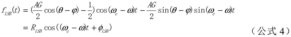
Equation 4 is an expression for calculating the amplitude and phase of the leaked image signal, where:

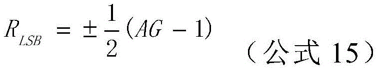
r in equation 5LSBIs the amplitude of the image signal, phiLSBIs the phase of the image signal. It can be seen that the unwanted sidebands are due to amplitude and phase imbalance of the IQ signal and the quadrature local oscillator signal.
The second step is that: determining a phase adjustment value required for image rejection
If the image leakage signal is to be eliminated, only the amplitude R of the image signal is requiredLSBIt is sufficient if 0.
Since the imbalance of the phase has a significant effect on the image rejection, it is assumed that the imbalance of the amplitude is negligible, i.e. the value of A, G enables AG- > 1.
Substituting AG 1 into equation 5, we get the amplitude equation of the image signal:
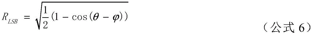
the output image signal energy can be seen It is related.
Since energy is proportional to the square of the amplitude, the power of the image signal can be expressed by equation 7:

wherein R is a fixed coefficient.
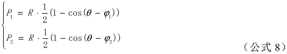
It is assumed that the phases of the IQ signals are respectively set so that the corresponding phase shifts are respectively Phase shift
 And
And the power of the corresponding image leakage signal can be measured and measured, and is set as P1And P2Formula 8 can be obtained by substituting formula 7:
solving equation 8 can yield fLO_I(t)、fLO_Q(t)Quadrature phase error between signals, equation 9:

according to equation 6, in order to make the amplitude R of the image signal LSB0, the following equation 10 can be obtained:
and thirdly, qmc _ phaseAB is calculated according to the DAC image suppression realization method.
The process of adjusting image rejection in a DAC is. There is a QMC in the DAC to perform image rejection. QMC comprises three parts: an I-way QMC gain register, a Q-way QMC gain register, and a phase adjustment register, for example, as shown in fig. 2. The I-path QMC gain register and the Q-path QMC gain register are used for adjusting amplitude imbalance, and the phase adjusting register is used for adjusting phase imbalance. The gain adjustment is a multiplier and the phase adjustment is performed by multiplying the Q-path signal by a coefficient and adding the multiplied signal to the I-path signal, which is noted to cause a change in the amplitude of the I-path signal, so that the amplitude effect is negligible when the coefficient is small enough and is not negligible when the coefficient is large.
The principle of phase adjustment is to multiply the signal of the Q path by a coefficient x and add it to the I path, as shown below.
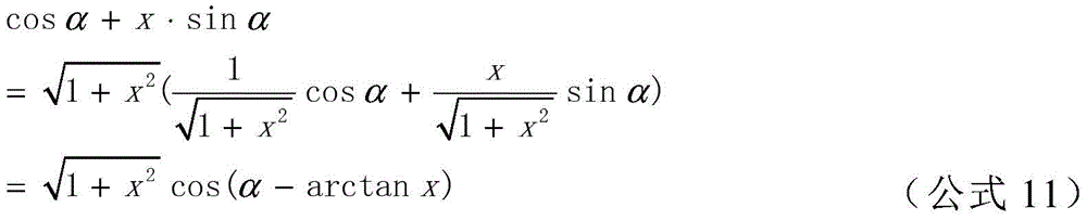
Cos α and sin α in equation 11 are expressions of a pair of quadrature modulated signals. And x is a coefficient for regulating the Q-path signal. The influence of the coefficient x on the phase and amplitude can be seen.
Since the coefficient x is small in value, x2Towards 0, equation 11 can be expressed as
cos α + x sin α ═ cos (α -arctan x) (equation 12)
From equation 12, the phase shift generated by the coefficient x
γ ═ arctan x (equation 13)
According to the DAC implementation principle:
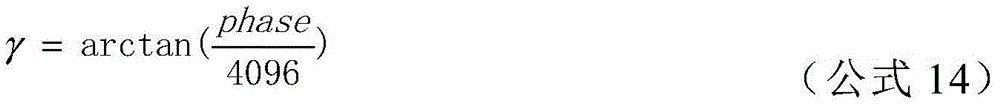
where γ is the phase shift, i.e. in equation 2 phase is the value of phase adjust register qmc _ phaseAB.
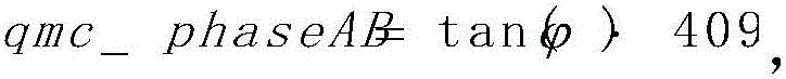
Transform equation 14 and calculate from equation 10 After the values are substituted, the value qmc _ phaseAB of the register is obtained as:

the phase adjustment value required for image rejection can be obtained.
Because of the fact thatObtained by The process can obtain two phase adjustment values. Therefore, the test can be set twice under the two phase adjustment values respectively, and the phase adjustment value with the lower leakage power value of the image leakage signal is taken as the optimal phase adjustment value and is set to the DAC.
The fourth step: and solving the amplitude adjustment value of image rejection.
Substituting equation 10 into equation 5 reduces to the following equation.
Since the energy is proportional to the square of the amplitude, the equation 15 is used to obtain
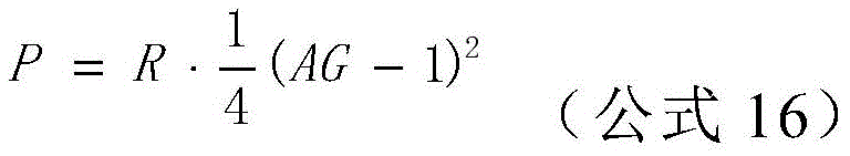
Wherein R is a fixed coefficient.
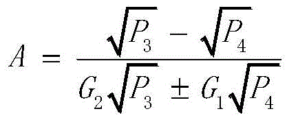
Similarly, let two amplitudes be G1、G2With the corresponding mirror leakage signal measured as P3、P4Substituting into equation 16 then yields the equation
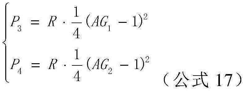
Solving equation 17 yields:

according to the DAC implementation principle:
qmc _ gainA ═ a 1024 (equation 19)
The amplitude adjustment value of the I-path signal can be obtained by substituting the value obtained by equation 18 into equation 19.
Since the obtained a is positive and negative values, equation 19 can obtain two amplitude adjustment values, and then the power values of the image leakage signal can be tested at the two amplitude adjustment values, respectively, and then the amplitude adjustment value of one of the image leakage signal and the leakage power value lower is taken as the amplitude adjustment value of the I-path signal and set to the DAC.
In addition, the amplitude adjustment value of the Q-path signal may be set such that the gain is 1, i.e., 1024. The values of all three registers in the DAC are now available.
Then, the three values are set in corresponding registers in the DAC, so that IQ image rejection of the RRU can reach a better level, and spurious indexes of corresponding frequency points are also better.
The principle of the present invention is explained above, and the method and apparatus for setting the mirror suppression parameter in IQ modulation according to the present invention are explained below.
Please refer to fig. 3, which is a flowchart illustrating a method for setting mirror image suppression parameters in IQ modulation according to an embodiment of the present invention. It includes:
step 31: presetting the phase offset of IQ signal of IQ modulator And
And and is obtained at
 And
And the power P of the mirror leakage signal of the IQ modulator1And P2。
Step 32: presetting a normalized amplitude ratio G between an I-path component and a Q-path component in an IQ signal of the IQ modulator1And G2And is obtained at G1And G2The power P of the mirror leakage signal of the IQ modulator3And P4。
Step 33: acquisition is based on P1And P2And a phase adjustment value in the image rejection parameter is obtained.
Step 34: acquisition is based on this G1、G2、P3And P4And obtaining a first amplitude adjustment value in the image rejection parameter, and obtaining a second amplitude adjustment value in the image rejection parameter which is a preset value. And
step 35: the phase adjust value qmc _ phaseAB, the first amplitude adjust value qmc _ gainA, and the second amplitude adjust value qmc _ gainB are set to an analog-to-digital converter DAC, wherein the DAC is a front-end circuit of the IQ modulator.
Wherein, in step 31, the phase offsets of the IQ signals input to the IQ modulator can be respectively set to And
And then testing at the same time
 And
And the power P of the mirror leakage signal of the IQ modulator1And P2(ii) a Finally according to P1And P2The quadrature phase error θ is calculated. Specifically, in calculating the quadrature phase error θ, the aforementioned formula (9) may be employed.
Here, in step 33, the aforementioned formula (10) and formula (14) may be adopted to calculate the phase adjustment value qmc _ phaseAB in the image rejection parameter.
As can be seen from equation (9), the quadrature phase error θ may include: first quadrature phase error theta1And a second quadrature phase error theta2. Then, at this point, the first quadrature phase error θ may be based1And a second quadrature phase error theta2Respectively calculating phase adjustment values to obtain a first phase adjustment value and a second phase adjustment value; then setting the first phase adjustment value and the second phase adjustment value to the DAC respectively, and then testing and obtaining the leakage power value of the mirror image leakage signal of the IQ modulator respectively to obtain a first leakage power value and a second leakage power value; and finally, taking the phase adjustment value corresponding to the smaller one of the first leakage power value and the second leakage power value as the phase adjustment value finally set to the DAC.
In steps 32 and 34, the IQ signal to the IQ modulator may be set such that the normalized amplitude ratio between the I-path component and the Q-path component in the IQ signal is G1And G2(ii) a Then at G1And G2Then, the power of the mirror leakage signal of the IQ modulator is respectively tested to obtain the power P3And P4(ii) a Finally according to G1、G2And P3And P4And calculating the normalized amplitude ratio A. Specifically, the normalized amplitude ratio a may be calculated by the aforementioned equation (17).
In step 34, the first amplitude adjustment value qmc _ gainA may be calculated according to the aforementioned formula (18), and then the second amplitude adjustment value qmc _ gainB is set to 1024.
Specifically, as shown in equation (17), the normalized amplitude ratio a may include: a first normalized amplitude ratio a1 and a second normalized amplitude ratio a 2. Then, the first amplitude adjustment value qmc _ gainA calculated according to a1 and a2 may be set to the DAC, respectively, and then the leakage power values of the mirror leakage signals in the IQ modulator may be tested, respectively, to obtain a first leakage power value corresponding to a1 and a second leakage power value corresponding to a 2; finally, the corresponding first amplitude adjustment value qmc _ gainA for the smaller of the first and second leakage power values is taken as the first amplitude adjustment value that is ultimately set to the DAC.
The method greatly reduces the times of testing the image leakage signal power, for example, eight times of tests can calculate the reasonable setting values of the DAC image suppression adjusting registers qmc _ gainA, qmc _ gainB and qmc _ phaseAB, thereby completing the adjustment of the image suppression parameters.
Fig. 4 is a schematic structural diagram of an embodiment of the setting device for mirror suppression parameters in IQ modulation according to the present invention. It includes:
a first processing module 41 for presetting the phase offset of the IQ signal of the IQ modulator And
And and is obtained at
 And
And the power P of the mirror leakage signal of the IQ modulator1And P2。
A second processing module 42 for presetting a normalized amplitude ratio G between the I-path component and the Q-path component in the IQ signal of the IQ modulator1And G2And is obtained at G1And G2The power P of the mirror leakage signal of the IQ modulator3And P4。
A third processing module 43 for obtaining a value based thereon P1And P2And a phase adjustment value in the image rejection parameter is obtained.
A fourth processing module 44 for obtaining a signal based on the G1、G2、P3And P4And obtaining a first amplitude adjustment value in the image rejection parameter, and obtaining a second amplitude adjustment value in the image rejection parameter which is a preset value.
A setting module 45, configured to set the phase adjustment value qmc _ phaseAB, the first amplitude adjustment value qmc _ gainA and the second amplitude adjustment value qmc _ gainB to an analog-to-digital converter DAC, wherein the DAC is a front-end circuit of the IQ modulator.
As shown in fig. 5, the third processing module 43 specifically includes: a first obtaining unit 431 for obtaining the data based on the P1And P2Obtaining the quadrature phase error between the I path component and the Q path component of the local oscillation signal used in the in-phase quadrature IQ modulator; and a
 second acquisition unit 432 for acquiring the phase adjustment value obtained based on a quadrature phase error between the I-path component and the Q-path component of the local oscillation signal.
In addition, from the previous analysis, the quadrature phase error θ acquired by the first acquiring unit 431 may include: first quadrature phase error theta1And a second quadrature phase error theta2. Therefore, the second obtaining unit 432 may obtain a first phase adjustment value and a second phase adjustment value obtained based on the first quadrature phase error and the second quadrature phase error, respectively; acquiring a first leakage power value and a second leakage power value of the mirror image leakage signal of the IQ modulator corresponding to the first phase adjustment value and the second phase adjustment value; and acquiring a phase adjustment value corresponding to the smaller one of the first leakage power value and the second leakage power value, and taking the phase adjustment value as the phase adjustment value finally set to the DAC.
As shown in fig. 6, the fourth processing module 44 includes: a third obtaining unit 441 for obtaining a value based on the G1、G2、P3And P4Obtaining the normalized amplitude ratio between the I-path component and the Q-path component of the local oscillation signal used in the IQ modulator; and a fourth obtaining unit 442 for obtaining the first amplitude adjustment value based on the normalized amplitude ratio between the I-path component and the Q-path component of the local oscillation signal.
As can be seen from the foregoing, the normalized amplitude ratio a acquired by the third acquisition unit 441 includes: a first normalized amplitude ratio a1 and a second normalized amplitude ratio a 2. Therefore, the fourth obtaining unit 442 may obtain a third amplitude adjustment value and a fourth amplitude adjustment value corresponding to the first normalized amplitude ratio and the second normalized amplitude ratio, respectively; respectively acquiring a first leakage power value and a second leakage power value of the mirror image leakage signal in the IQ modulator corresponding to the third amplitude adjustment value and the fourth amplitude adjustment value; and obtaining a corresponding amplitude adjustment value of the smaller one of the first leakage power value and the second leakage power value as the first amplitude adjustment value finally set to the DAC.
Fig. 7 is a schematic structural diagram of an embodiment of a remote radio unit according to the present invention, where the remote radio unit includes: an IQ modulator 100, a DAC200 and a setting device 300, wherein the DAC200 is connected to the IQ modulator 100, and is configured to process a baseband signal and transmit the processed baseband signal to the IQ modulator for IQ modulation. The DAC200 may include: a phase adjustment register 202, a first gain adjustment register 201, and a second gain adjustment register 203; and the setting means 300 may be used to set the values in the phase adjustment register, the first gain adjustment register and the second gain adjustment register in the DAC. Wherein, the specific structure of the IQ modulator 100 can be as shown in fig. 1, the specific structure of the DAC200 can be as shown in fig. 2, and the structure of the setting apparatus 300 can be as shown in fig. 4.
In the above embodiments, the number of times of testing the power of the image leakage signal can be greatly reduced, for example, the phase adjustment value and the two gain adjustment values in the DAC can be set by testing the power value of the image leakage signal for eight times.
It should be noted that all modules related to the present invention are logic modules, and in practical applications, one logic unit may be one physical unit, may also be a part of one physical unit, and may also be implemented by a combination of multiple physical units. In addition, in order to highlight the innovative part of the present invention, elements that are not so closely related to solving the technical problems proposed by the present invention are not introduced in the present embodiment, but this does not indicate that other elements are not present in the present embodiment.
It will be understood by those skilled in the art that all or part of the processes of the methods of the above embodiments may be implemented by a computer program, which can be stored in a computer-readable storage medium, and when executed, can include the processes of the embodiments of the methods described above. The storage medium may be a magnetic disk, an optical disk, a Read-Only Memory (ROM), a Random Access Memory (RAM), or the like.
It will be understood by those of ordinary skill in the art that the foregoing embodiments are specific examples for carrying out the invention, and that various changes in form and details may be made therein without departing from the spirit and scope of the invention in practice.
Claims (21)


Priority Applications (1)
| Application Number | Priority Date | Filing Date | Title |
|---|---|---|---|
| CN201610482310.0A CN107547458B (en) | 2016-06-28 | 2016-06-28 | Method, device and remote radio unit for setting image suppression parameters in IQ modulation |
Applications Claiming Priority (1)
| Application Number | Priority Date | Filing Date | Title |
|---|---|---|---|
| CN201610482310.0A CN107547458B (en) | 2016-06-28 | 2016-06-28 | Method, device and remote radio unit for setting image suppression parameters in IQ modulation |
Publications (2)
| Publication Number | Publication Date |
|---|---|
| CN107547458A CN107547458A (en) | 2018-01-05 |
| CN107547458B true CN107547458B (en) | 2021-04-20 |
Family
ID=60961516
Family Applications (1)
| Application Number | Title | Priority Date | Filing Date |
|---|---|---|---|
| CN201610482310.0A Active CN107547458B (en) | 2016-06-28 | 2016-06-28 | Method, device and remote radio unit for setting image suppression parameters in IQ modulation |
Country Status (1)
| Country | Link |
|---|---|
| CN (1) | CN107547458B (en) |
Families Citing this family (5)
| Publication number | Priority date | Publication date | Assignee | Title |
|---|---|---|---|---|
| CN108040029B (en) | 2018-01-12 | 2020-06-02 | 深圳锐越微技术有限公司 | Method, device and equipment for compensating IQ two-path imbalance of receiver |
| CN110868227B (en) * | 2018-08-28 | 2022-02-25 | 瑞昱半导体股份有限公司 | Transmission circuit capable of measuring image rejection ratio of transmission end |
| CN112671681B (en) * | 2020-02-03 | 2022-03-01 | 腾讯科技(深圳)有限公司 | Sideband suppression method, apparatus, computer equipment and storage medium |
| CN114531331B (en) * | 2022-02-07 | 2024-07-19 | 北京奕斯伟计算技术股份有限公司 | IQ signal calibration method and device |
| CN114944845B (en) * | 2022-06-16 | 2023-03-10 | 北京大有半导体有限责任公司 | Image interference suppression method and device, electronic equipment and low/zero intermediate frequency receiver |
Family Cites Families (4)
| Publication number | Priority date | Publication date | Assignee | Title |
|---|---|---|---|---|
| CN101075816B (en) * | 2006-05-19 | 2012-05-23 | 大唐移动通信设备有限公司 | Method for inhibiting digital frequency-variable image |
| US8064550B2 (en) * | 2007-03-09 | 2011-11-22 | Qualcomm, Incorporated | Quadrature imbalance estimation using unbiased training sequences |
| CN102025666B (en) * | 2010-12-15 | 2015-06-03 | 中兴通讯股份有限公司 | Method and device for realizing IQ signal correction in base station transmitter equipment |
| US20130128931A1 (en) * | 2011-11-17 | 2013-05-23 | Aviacomm Inc. | On-chip radio calibration |
-
2016
- 2016-06-28 CN CN201610482310.0A patent/CN107547458B/en active Active
Also Published As
| Publication number | Publication date |
|---|---|
| CN107547458A (en) | 2018-01-05 |
Similar Documents
| Publication | Publication Date | Title |
|---|---|---|
| TWI551038B (en) | Apparatus and method for amplitude modulation to phase modulation (ampm) distortion compensation | |
| CN107547458B (en) | Method, device and remote radio unit for setting image suppression parameters in IQ modulation | |
| CN100481828C (en) | Amplitude imbalance compensation of quadrature modulator | |
| US9749172B2 (en) | Calibration method and calibration apparatus for calibrating mismatch between first signal path and second signal path of transmitter/receiver | |
| CN101815056B (en) | IQ unbalanced calibration method and equipment of baseband signals in wireless communication receiving machine | |
| TWI416899B (en) | Method and apparatus for correcting mismatch between in-phase/orthogonal signals in a communication circuit | |
| CN105282062B (en) | Method and apparatus for correcting mismatch between signal paths of transmitter/receiver | |
| JPH07105775B2 (en) | Vector modulator calibration method | |
| US10374643B2 (en) | Transmitter with compensating mechanism of pulling effect | |
| US8224269B2 (en) | Vector modulator calibration system | |
| CN114374593A (en) | IQ imbalance compensation method for WiFi broadband transceiving path and application | |
| US8831076B2 (en) | Transceiver IQ calibration system and associated method | |
| CN1649334B (en) | Apparatus and method for adjusting quadrature modulator, and communication apparatus | |
| US11671131B2 (en) | Transmitter circuit, compensation value calibration device and method for calibrating IQ imbalance compensation values | |
| CN108040029B (en) | Method, device and equipment for compensating IQ two-path imbalance of receiver | |
| US20190190451A1 (en) | Methods, circuits, and apparatus for calibrating an in-phase and quadrature imbalance | |
| US9385822B2 (en) | Wideband calibration method and wideband calibration apparatus for calibrating mismatch between first signal path and second signal path of transmitter/receiver | |
| CN103023834A (en) | Unbalance compensator, unbalance compensation method and direct down-conversion receiving device | |
| CN104821826A (en) | Method and system for automatic correction of broadband vector signal | |
| CN104811215B (en) | A kind of IQ imbalance compensations apparatus and method | |
| CN101442511A (en) | Method and apparatus for improving radio frequency index of zero intermediate frequency transmitter | |
| US20230253994A1 (en) | Transmitter circuit, compensation value calibration device and method for calibrating compensation values | |
| WO2020125790A1 (en) | Polar transmitter with feedthrough compensation | |
| CN100508411C (en) | Correcting unit and method for mismatching of in-phase signal and quadrature-phase signal | |
| CN109379146B (en) | A Circuit Parameter Correction Method of Quadrature Modulator |
Legal Events
| Date | Code | Title | Description |
|---|---|---|---|
| PB01 | Publication | ||
| PB01 | Publication | ||
| SE01 | Entry into force of request for substantive examination | ||
| SE01 | Entry into force of request for substantive examination | ||
| GR01 | Patent grant | ||
| GR01 | Patent grant |