CN107527336B - Lens relative position calibration method and device - Google Patents
Lens relative position calibration method and device Download PDFInfo
- Publication number
- CN107527336B CN107527336B CN201610460780.7A CN201610460780A CN107527336B CN 107527336 B CN107527336 B CN 107527336B CN 201610460780 A CN201610460780 A CN 201610460780A CN 107527336 B CN107527336 B CN 107527336B
- Authority
- CN
- China
- Prior art keywords
- lenses
- calibration plate
- lens
- panoramic image
- image formed
- Prior art date
- Legal status (The legal status is an assumption and is not a legal conclusion. Google has not performed a legal analysis and makes no representation as to the accuracy of the status listed.)
- Active
Links
- 238000000034 method Methods 0.000 title claims abstract description 38
- 238000003384 imaging method Methods 0.000 claims abstract description 163
- 238000012545 processing Methods 0.000 claims abstract description 23
- 230000000007 visual effect Effects 0.000 claims abstract description 11
- 239000011159 matrix material Substances 0.000 claims description 25
- 239000003550 marker Substances 0.000 claims description 10
- 230000001131 transforming effect Effects 0.000 claims description 4
- 238000012937 correction Methods 0.000 claims description 3
- 230000006870 function Effects 0.000 description 18
- 238000010586 diagram Methods 0.000 description 16
- 230000003287 optical effect Effects 0.000 description 10
- 238000004590 computer program Methods 0.000 description 9
- 230000008569 process Effects 0.000 description 8
- 238000005516 engineering process Methods 0.000 description 5
- 238000004519 manufacturing process Methods 0.000 description 4
- 230000004048 modification Effects 0.000 description 3
- 238000012986 modification Methods 0.000 description 3
- 238000001514 detection method Methods 0.000 description 2
- 230000005540 biological transmission Effects 0.000 description 1
- 230000008859 change Effects 0.000 description 1
- 238000011161 development Methods 0.000 description 1
- 230000000694 effects Effects 0.000 description 1
- 230000006872 improvement Effects 0.000 description 1
- 238000013507 mapping Methods 0.000 description 1
- 239000007787 solid Substances 0.000 description 1
- 230000003068 static effect Effects 0.000 description 1
Images


Landscapes
- Studio Devices (AREA)
- Stereoscopic And Panoramic Photography (AREA)
Abstract
The application discloses a method and a device for calibrating relative positions of lenses. The calibration method comprises the following steps: acquiring a calibration plate image formed by shooting a calibration plate by each lens in at least two lenses with relative position relation to be calibrated, wherein the calibration plate is positioned in a visual field overlapping area of the at least two lenses, and mark points are arranged on the calibration plate; carrying out panoramic image expansion processing on the calibration plate image formed by each lens to obtain a target imaging position of the mark point in the panoramic image corresponding to the calibration plate image formed by each lens; and aligning the target imaging positions of the mark points in the panoramic image corresponding to the calibration plate image formed by the lenses so as to determine the relative position relationship among the lenses. The method and the device can calibrate the relative position between the lenses in the panoramic camera more accurately, and further improve the image quality obtained by splicing the images based on the calibration result.
Description
Technical Field
The present application relates to the field of digital image processing technologies, and in particular, to a method and an apparatus for calibrating a relative position of a lens.
Background
With the development of visual image technology and video acquisition technology, video acquisition has been developed from acquiring videos at common viewing angles, to wide-angle videos, and further to panoramic videos at 360 degrees in the horizontal direction and 360 degrees in the vertical direction. In order to acquire a panoramic image, a panoramic camera is composed of two or more lenses, and images in multiple directions shot by the two or more lenses are spliced into the panoramic image.
In a panoramic camera consisting of two wide-angle lenses, two imaging modules are included back-to-back, wherein the field of view of the wide-angle lens in each imaging module exceeds 180 degrees. In the production and assembly process of the panoramic camera, due to the error of assembly precision, the optical center of the wide-angle lens and the center of an imaging image are not necessarily completely coincident, and relative rotation also exists between the imaging planes of the two wide-angle lenses. It is therefore necessary to calibrate the relative position between the two wide-angle lenses during production.
In the prior art, a real scene is shot, an angular point in the real scene in an image is detected, matching is performed between imaging of two lenses, a relative position between the two lenses is determined, and then the image is stretched based on the relative position to complete compensation of assembly errors between the lenses. However, because the distances from the corner points in the real scene to the lenses are different, the relative positions between the lenses cannot be accurately calibrated by the existing scheme, and therefore ghost areas and blind areas of the spliced images are obvious based on the calibration result.
Disclosure of Invention
Aspects of the present disclosure provide a method and an apparatus for calibrating relative positions of lenses, which are used to calibrate relative positions of lenses in a panoramic camera more accurately, so as to improve image quality obtained by image stitching based on a calibration result.
The embodiment of the application provides a method for calibrating relative positions of lenses, which comprises the following steps:
acquiring a calibration plate image formed by shooting a calibration plate by each lens in at least two lenses with relative position relation to be calibrated, wherein the calibration plate is positioned in a visual field overlapping area of the at least two lenses, and mark points are arranged on the calibration plate;
carrying out panoramic image expansion processing on the calibration plate image formed by each lens to obtain a target imaging position of the mark point in the panoramic image corresponding to the calibration plate image formed by each lens;
and aligning the target imaging positions of the mark points in the panoramic image corresponding to each calibration plate image to determine the relative position relationship among the lenses.
The embodiment of the present application further provides a lens relative position calibration apparatus, including:
the calibration plate image acquisition module is used for acquiring a calibration plate image formed by shooting a calibration plate by each lens in at least two lenses with relative position relation to be calibrated, the calibration plate is positioned in a visual field overlapping area of the at least two lenses, and the calibration plate is provided with mark points;
the imaging position acquisition module is used for carrying out panoramic image expansion processing on the calibration plate image formed by each lens so as to obtain a target imaging position of the mark point in the panoramic image corresponding to the calibration plate image formed by each lens;
and the position relation calibration module is used for aligning the target imaging positions of the mark points in the panoramic image corresponding to each calibration plate image so as to determine the relative position relation among the lenses.
In the process of calibrating the relative position relationship between the lenses according to the embodiment of the application, the calibration plate located in the overlapping area of the visual fields of at least two lenses to be calibrated to the relative position relationship is used to replace a real scene, the calibration plate image formed by shooting the calibration plate by each lens is expanded into a panoramic image, and the alignment relationship of the imaging positions of the mark points on the calibration plate in the panoramic image corresponding to the calibration plate image formed by each lens is used to determine the relative position relationship between the lenses, so that the problem of inconsistent distances from the corner points to the lenses in the real scene is solved, the relative position relationship between the calibrated lenses has high precision, and the image quality obtained by image splicing based on the calibration result is improved.
Drawings
The accompanying drawings, which are included to provide a further understanding of the application and are incorporated in and constitute a part of this application, illustrate embodiment(s) of the application and together with the description serve to explain the application and not to limit the application. In the drawings:
fig. 1 is a schematic flowchart of a method for calibrating a relative position of a lens according to an embodiment of the present application;
FIG. 2 is a schematic diagram illustrating a positioning of a calibration plate in an overlapping area of the fields of view of the lenses according to another embodiment of the present disclosure;
FIG. 3 is a schematic view of a checkerboard pattern employed by a calibration plate provided in accordance with yet another embodiment of the present application;
FIG. 4 is a schematic diagram of equidistant dot patterns used in a calibration plate according to yet another embodiment of the present application;
FIG. 5 is a schematic flow chart diagram illustrating one implementation of step 103 provided by yet another embodiment of the present application;
FIG. 6 is a schematic diagram of an imaging circle of a detection lens according to yet another embodiment of the present application;
FIG. 7 is a schematic diagram of an imaging model of each lens according to yet another embodiment of the present application;
fig. 8 is a schematic structural diagram of a lens relative position calibration apparatus according to another embodiment of the present application;
fig. 9 is a schematic structural diagram of a lens relative position calibration apparatus according to yet another embodiment of the present application.
Detailed Description
In order to make the objects, technical solutions and advantages of the present application more apparent, the technical solutions of the present application will be described in detail and completely with reference to the following specific embodiments of the present application and the accompanying drawings. It should be apparent that the described embodiments are only some of the embodiments of the present application, and not all of the embodiments. All other embodiments, which can be derived by a person skilled in the art from the embodiments given herein without making any creative effort, shall fall within the protection scope of the present application.
In the prior art, a real scene is shot, matching is performed between lens images based on angular points in the real scene, the relative position between lenses is determined, and then the images are stretched based on the relative position, so that the assembly error between lenses is compensated. However, because the distances from the corner points in the real scene to the lenses are different, the relative position precision between the lenses calibrated by the existing method is poor, and the ghost regions and blind regions of the spliced images based on the calibration result are obvious.
In view of the above problems, an embodiment of the present application provides a solution, and the main principle is: the calibration plates are placed in the overlapped areas of the visual fields of at least two lenses of which the relative position relations are to be calibrated, the calibration plates are used for replacing a real scene, the alignment relations of the mark points on the calibration plates in the imaging positions of the panoramic image corresponding to the calibration plate image formed by each lens are used for determining the relative position relations among the lenses, the problem that the distances from the corner points in the real scene to the lenses are different is solved, the relative position relations among the calibrated lenses are high in precision, and the image quality obtained by image splicing based on the calibration results is improved.
The technical solutions provided by the embodiments of the present application are described in detail below with reference to the accompanying drawings.
Fig. 1 is a schematic flow chart of a lens relative position calibration method according to an embodiment of the present application. As shown in fig. 1, the method includes:
101. the method comprises the steps of obtaining a calibration plate image formed by shooting a calibration plate by each lens in at least two lenses with relative position relation to be calibrated, wherein the calibration plate is positioned in a visual field overlapping area of the at least two lenses, and mark points are arranged on the calibration plate.
103. And carrying out panoramic image expansion processing on the calibration plate image formed by each lens to obtain the target imaging position of the mark point in the panoramic image corresponding to the calibration plate image formed by each lens.
105. And aligning the target imaging positions of the mark points in the panoramic image corresponding to each calibration plate image to determine the relative position relationship among the lenses.
In practical applications, in order to acquire a panoramic image, panoramic photographing apparatuses, such as a panoramic camera, and the like, have appeared. The panoramic shooting devices comprise at least two lenses, and during production and assembly, due to errors of assembly precision, the lenses are rotated relatively, namely, imaging planes of the lenses are rotated relatively, but not located on the same plane. Therefore, the relative position between the lenses in the panorama photographing apparatus needs to be calibrated. The method provided by the embodiment can be used for calibrating the relative position relationship between the lenses in the panoramic shooting equipment. Of course, besides the application scene of the panoramic shooting device, the method provided by the embodiment may also be adopted for other application scenes that need to calibrate the relative external relationship between the lenses.
It should be noted that the present embodiment does not limit the type of the at least two lenses to be calibrated in terms of relative position. Optionally, the at least two lenses to be determined with the relative position relationship may be wide-angle lenses, such as fisheye lenses, but not limited thereto.
In this embodiment, a calibration plate is placed in an overlapping area of the fields of view of at least two lenses to be calibrated in a relative position relationship, so as to ensure that each lens in the at least two lenses can shoot the calibration plate. Thus, each lens of the at least two lenses can shoot the calibration plate at the same time to form respective calibration plate images.
Optionally, the calibration plate is not only located in the overlapping area of the fields of view of the at least two lenses, but also a line connecting the center of the calibration plate and the optical center of the imaging device formed by the at least two lenses is perpendicular to the calibration plate. The following description will be made of the placement of the calibration plate with reference to fig. 2:
assuming that the lens 22 and the lens 23 are two lenses to be calibrated in a relative positional relationship, the lens 22 and the lens 23 are assembled back-to-back. The calibration plate 21 is placed in the overlapping area of the fields of view of the lens 22 and the lens 23, and it is ensured that a line connecting the center of the calibration plate 21 and the optical center of the imaging device constituted by the lens 22 and the lens 23 is perpendicular to the calibration plate 21. The broken line in fig. 2 indicates a line connecting the center of the calibration plate 21 and the optical center of the imaging device constituted by the lens 22 and the lens 23, which line is perpendicular to the calibration plate 21 as shown in fig. 2.
Optionally, in consideration of that at least two lenses to be calibrated in relative position relationship are provided, and an imaging device formed by the at least two lenses has a characteristic of wide shooting visual angle, so that a calibration plate can be placed at least three specified positions, and thus the imaging device can be ensured to shoot images of the calibration plate from multiple angles.
In an alternative embodiment, the same calibration plate may be placed in each of at least three positions in advance, so that each of at least two lenses to be calibrated in a relative position relationship may capture multiple calibration plate images at one time, and the efficiency of obtaining the calibration plate images is high. It should be noted that for each of the at least three calibration plates, the calibration plate is located in the overlapping area of the fields of view of the at least two lenses. Further optionally, a line connecting the center of each calibration plate and the optical center of the imaging device formed by the at least two lenses is perpendicular to the calibration plate.
In another alternative embodiment, a single calibration plate may be used, and a rotating jig is used to rotate at least two lenses to be calibrated in a relative position relationship for multiple times, so that the calibration plate is located at least three designated positions, and for the at least two lenses, the calibration plate is photographed when the calibration plate is located at different positions. This way the number of calibration plates can be reduced.
Based on the above, the obtaining of the calibration plate image in the step 101 specifically includes: each of the at least two lenses to be calibrated in the relative position relationship may acquire at least three calibration plate images obtained by the lens shooting the calibration plate at the specified at least three positions.
Further, in subsequent steps 103 and 105, the relative position relationship between the lenses can be calibrated according to the calibration plate images shot by the lenses from different angles, so as to further improve the accuracy of the calibration result.
In addition, the calibration plate of the present embodiment is provided with a marking point. The calibration plate image formed by each lens comprises the imaging position of the mark point. Alternatively, the calibration plate may adopt a checkerboard pattern, the checkerboard pattern is shown in fig. 3, and part or all of the checkerboards in the checkerboard pattern may be used as the mark points. Alternatively, the calibration plate may adopt an equidistant dot pattern as shown in fig. 4, and some or all of the dots in the equidistant dot pattern may be used as the marking points.
With continued reference to fig. 1, after the calibration board images formed by the respective lenses are acquired, step 103 is executed, in which the panoramic image expansion processing is performed on the calibration board images formed by the respective lenses to obtain target imaging positions of the mark points in the panoramic image corresponding to the calibration board images formed by the respective lenses.
Consider that some lenses, such as fisheye lenses, have significant imaging distortion. If the lenses to be calibrated in the relative position relationship comprise the lenses with larger imaging distortion, the distortion of the calibration plate images shot by the lenses is larger, so that the relative position relationship between the lenses is calibrated directly according to the imaging positions of the calibration points in the calibration plate images, and the precision is lower. Therefore, in the embodiment, the calibration board image formed by each lens is expanded into the panoramic image, and the relative position relationship between the lenses is calibrated based on the imaging position of the mark point in the panoramic image, so that the precision of the calibration result is improved.
As shown in fig. 5, an alternative implementation of step 103 includes:
1031. and according to the appointed panorama expansion model, carrying out panorama expansion processing on the calibration plate image formed by each lens to obtain the initial imaging position of the mark point in the panorama image corresponding to the calibration plate image formed by each lens.
For each shot, it involves two coordinate systems. One is the imaging coordinate system of the lens, called the imaging plane coordinate system, and one is the spatial coordinate system in which the lens is located. The imaging model of the lens is mainly used for reflecting the mapping relation between a space point in a space coordinate system and an imaging position in an imaging plane coordinate system, so that the imaging model of the lens can be constructed depending on the imaging plane coordinate system and the space coordinate system. The process of constructing the image model is as follows:
firstly, under the imaging plane coordinate system of the lens, imaging circle detection is carried out on an image of a specified object shot by the lens so as to determine the imaging circle of the lens.
Optionally, a designated object may be placed in front of the lens, and the lens may be used to capture the designated object to obtain an image of the designated object. In placing a specified object, the specified object is required to cover the field of view of the lens.
In addition, the present embodiment does not limit the designated object, for example, the designated object may be a bowl-shaped, cylindrical or square light source.
Further, one embodiment of the above determining the imaging circle of the lens includes:
determining a pixel position with a brightness value meeting a preset requirement as a boundary of an imaging circle according to the brightness of the image of the specified object; for example, a position where the luminance value changes steepest may be determined as the boundary of the imaging circle, or a position where the luminance value is smallest may be determined as the boundary of the imaging circle, or a center position where the luminance value changes most may be determined as the boundary of the imaging circle, or the like; according to the coordinates of at least two boundary points according to the formula And performing curve fitting to obtain the center and the radius of the imaging circle. As shown in fig. 6, a rectangular frame represents the image 1 of the specified object, and a circle within the rectangular frame represents the
 imaging circle 11. Alternatively to this, the first and second parts may,the luminance of the pixel can be detected gradually along a straight line from the center to the outside in fig. 6.
In the above formula, r0Is the radius of the imaging circle, (u)0,v0) The coordinates of the center of the imaging circle are obtained; (x)i,yi) And setting the number of the at least two boundary points as m, wherein i is more than or equal to 1 and less than or equal to m, and m is a natural number more than or equal to 2.
Optionally, the centers and the radii of the different lenses may be distinguished by a superscript, for example, the center of an imaging circle of a jth lens of at least two lenses may be marked as the center of a circle The radius is given as
 j is a natural number.
Then, an imaging model of the lens is constructed based on the space coordinate system of the lens and the imaging circle of the lens.
With reference to fig. 7, the correspondence between the spatial coordinate system and the imaging plane coordinate system is explained:
as shown in fig. 7, the spatial coordinate system and the imaging plane coordinate system both use the center O of the imaging circle 11 as the origin of coordinates; the X-axis and Y-axis of the spatial coordinate system correspond to the u-axis and v-axis of the imaging plane coordinate system, only the u-axis and v-axis being shown in fig. 7; the Z-axis of the space coordinate system is perpendicular to the u-axis and the v-axis, and the Z-axis is actually the optical axis direction of the lens.
To facilitate understanding of the concept of space, a half unit ball 2 is shown in fig. 7.
Optionally, an imaging model of each lens is as follows:

the principle of the above imaging model is explained with reference to fig. 7:
assuming that an imaging position of a spatial point P on the imaging circle 11 in the spatial coordinate system is Q (u, v), an included angle between a line connecting the spatial point P and a center O of the imaging circle 11 and the Z axis is theta, an intersection point between a line OP of the center O of the imaging circle 11 and the spatial point P and the unit sphere 2 is P', and an included angle between a line OQ of the center O of the imaging circle 11 and the imaging position Q of the spatial point P on the imaging circle 11 and the u axis (or X axis) is P
In the above imaging model, r (θ) represents the distance from the imaging position Q of the spatial point P within the imaging circle 11 to the center O of the imaging circle 11; k is a radical ofiIs the imaging coefficient; n is the order of the imaging model and n is a natural number.
In conjunction with the imaging model shown in fig. 7, the imaging positions of the marker points in the calibration plate image formed by each lens can be determined. For example, the imaging position of the landmark point in the calibration plate image formed by each lens may be automatically detected by a susan (small unambiguous segment assembling cycle) operator or a Harris operator, but is not limited thereto.
And finally, according to the appointed panoramic image expansion model, converting the imaging positions of the mark points in the calibration plate image formed by each lens to obtain the initial imaging positions of the mark points in the panoramic image corresponding to the calibration plate image formed by each lens.
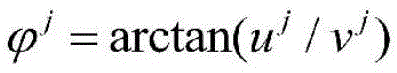
The coordinates of the image points in the calibration plate image are (u, v), and belong to an imaging plane coordinate system, namely a uv coordinate system; and the coordinate system of the panoramic image is Coordinate system, i.e. the coordinates of the panoramic image being
 Wherein,
 the value of theta can be determined according toThe same model.
For example, the calibration plate image may be expanded into a panoramic image using an isometric projection model or an isometric angle projection model. Wherein, the expansion formula of the equidistant projection model is as follows: r ═ f θ, and the expansion formula of the equal solid angle projection model is: r is 2fsin (θ/2). According to the expansion formula and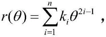 θ ═ f (r) can be obtained.
Wherein f is the focal length of each lens, and theta is the included angle between the mark point and the optical axis of each lens, namely the included angle between the connecting line of the mark point and the center of the imaging circle of each lens and the Z axis; r is the distance between the imaging position of the mark point in the calibration plate image and the center of the imaging circle of each lens; f represents a function represented by the above expansion formula and and (5) deducing the relation between theta and r.
Based on the above, the imaging position (u) of the marker point in the calibration plate image formed by the jth lensj,vj) The initial imaging position in the panoramic image can be converted according to the following formula

θj=F(rj)
1032. Taking any one of the at least two lenses as a reference lens, and directly taking the initial imaging position of the mark point in the panoramic image corresponding to the calibration plate image formed by the reference lens as the target imaging position of the mark point in the panoramic image corresponding to the calibration plate image formed by the reference lens.
After the initial imaging position of the mark point in the panoramic image corresponding to the calibration plate image formed by each lens is obtained, any lens can be selected from at least two lenses as a reference lens, and the panoramic image corresponding to the calibration plate image formed by the reference lens is used as a reference panoramic image, so that the panoramic images corresponding to the calibration plate images formed by other lenses are aligned with the reference panoramic image. Therefore, the initial imaging position of the panoramic image corresponding to the calibration plate image formed by the marker point in the reference lens can be directly used as the target imaging position of the marker point in the panoramic image corresponding to the calibration plate image formed by the reference lens.
1033. And correcting the initial imaging positions of the mark points in the panoramic image corresponding to the calibration plate image formed by the other lenses according to the rotation matrix representing the relative position relationship between the reference lens and the other lenses in the at least two lenses so as to obtain the target imaging positions of the mark points in the panoramic image corresponding to the calibration plate image formed by the other lenses.
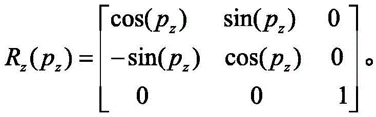
Based on the reference lens, the other lenses are rotated in position with respect to the reference lens. The rotation angle in three directions in the space coordinate system is used for representing the rotation relation of the other lenses and the reference lens in position. The rotation angles in the three directions are respectively expressed as: p is a radical ofx、pyAnd pzThen, the rotation matrix T representing the relative positional relationship between the reference lens and the other lenses is as follows:
T=RxRyRz
wherein,
the rotation matrixes representing the relative position relationship between the different lenses and the reference lens are different, and the different lenses can be distinguished through the upper corner mark. For example, forThe k lens, a rotation matrix representing the relative position relationship between the k lens and the reference lens can be recorded as The reference shot is a shot other than the k-th shot.
Considering that each rotation angle in the rotation matrix is in the space coordinate system, the correction of the initial imaging position can be accomplished by, but not limited to, the following ways:
firstly, converting an initial imaging position of a mark point in a panoramic image corresponding to a calibration plate image formed by other lenses into a coordinate position of the mark point in a space coordinate system;
optionally, the landmark point corresponds to a coordinate position in the spatial coordinate system, and may be represented as: the coordinate position of the intersection of the line connecting the landmark point and the center of the imaging circle and the unit sphere 2 in the spatial coordinate system is not limited thereto. For example, the imaging position in the panoramic image may be set in the following manner Transformed into the coordinate position (x, y, z) in the spatial coordinate system of the intersection of the connecting line of the landmark point and the center of the imaging circle and the unit sphere 2:


z=cos(θ)。
based on the above, the initial imaging position of the mark point in the panoramic image corresponding to the calibration board image formed by the k-th lens Transformation into a landmark point corresponds to a coordinate position (x) in a spatial coordinate systemk,yk,zk):


zk=cos(θk)。
Then, correcting the coordinate position of the mark point in the space coordinate system according to the rotation matrix to obtain the corrected coordinate position of the mark point in the space coordinate system;
for example, the rotation matrix may be directly multiplied by the index point to correspond to the coordinate position in the spatial coordinate system, and the multiplied result may be used as the index point to correspond to the corrected coordinate position in the spatial coordinate system. Taking the k lens as an example, the mark point corresponds to the corrected coordinate position in the space coordinate system
And finally, inversely transforming the coordinate position of the mark point after being corrected in the space coordinate system into the panoramic image corresponding to the calibration plate image formed by other lenses so as to obtain the target imaging position of the mark point in the panoramic image corresponding to the calibration plate image formed by other lenses.
Optionally, the above-mentioned correlation formula may be inversely transformed to obtain the target imaging position The formula of (1) is as follows:


taking the k-th lens as an example, the mark point is at the target imaging position in the panoramic image corresponding to the calibration plate image formed by the k-th lens The following were used:


with continued reference to fig. 1, after obtaining the target imaging positions of the mark points in the panoramic image corresponding to the calibration board image formed by each lens, step 103 is executed, i.e. the target imaging positions of the mark points in the panoramic image corresponding to the calibration board image formed by each lens are aligned to determine the relative position relationship between each lens.
For each lens, if there is no relative rotation between the lenses, the imaging planes of the lenses are on the same plane, and correspondingly, the panoramic images corresponding to the imaging planes of the lenses are also on the same plane. This means that the imaging positions of the same marker point in the calibration plate image made by each lens are aligned, and the imaging positions of the marker point in the panoramic image corresponding to the calibration plate image made by each lens are aligned. The alignment means that the coordinate values corresponding to the imaging positions are the same.
On the contrary, if there is a relative rotation between the lenses, there is a rotation between the imaging planes of the lenses, and correspondingly, there is a rotation between the panoramic images corresponding to the imaging planes of the lenses. This means that the imaging positions of the same marker point in the calibration plate image made by each lens are not aligned, and the imaging positions of the marker point in the panoramic image corresponding to the calibration plate image made by each lens are not aligned. The non-alignment means that the coordinate values corresponding to the imaging positions are different.
The misalignment relationship of the mark points in the imaging positions of the panoramic image corresponding to the calibration plate image formed by the lenses reflects the relative position relationship between the lenses. Based on the method, the target imaging positions of the mark points in the panoramic image corresponding to the calibration plate image formed by the lenses can be aligned to determine the relative position relationship between the lenses.
When determining the relative positional relationship between the lenses, it is necessary to select one lens as a reference lens. Any one of the at least two lenses may be used as a reference lens.
Based on the above, a rotation matrix representing the relative positional relationship between the reference lens and the other lens can be acquired. Constructing a distance error function by taking the rotation matrix as a variable according to a target imaging position of a mark point in a panoramic image corresponding to a calibration plate image formed by the reference lens and other lenses; and solving by taking the minimum distance error function as a target to obtain a rotation matrix representing the relative position relationship between the reference lens and other lenses.
For example, taking the reference lens and the kth lens as an example, the following distance error function may be constructed:

in the above formula, GkRepresenting a distance error function corresponding to the kth lens; n represents the total number of marker points; representing the target imaging position of the ith mark point in the panoramic image corresponding to the calibration plate image formed by the kth lens;
 and the target imaging position of the ith marking point in the panoramic image corresponding to the calibration plate image formed by the reference lens is shown. Wherein the rotation matrix between the kth lens and the reference lens is
 And
And see the above formula for details.
Further, if each lens captures calibration plates at least three specified positions to obtain at least three calibration plate images, the distance error functions for each calibration plate image may be added as a final distance error function. Still taking the reference lens and the kth lens as an example, in the case of capturing a plurality of calibration plate images, the following distance error function may be constructed:

in the above-mentioned formula, representing a final distance error function corresponding to the k lens; h represents the total number of the calibration board images;
 the distance error function corresponding to the 1 st calibration plate image formed by the kth lens is represented;
 the distance error function corresponding to the 2 nd calibration plate image formed by the kth lens is represented;
 and the distance error function corresponding to the h-th calibration plate image formed by the k-th lens is shown.
It should be noted that the above-mentioned obtaining of the rotation matrix representing the relative position relationship between the reference lens and the other lenses mainly means obtaining the rotation angles p in three directions in the rotation matrixx、pyAnd pz。
As can be seen from the above description, in the process of calibrating the relative position relationship between the lenses in the embodiment of the present application, the calibration plate located in the overlapping area of the fields of view of at least two lenses to be calibrated with respect to the relative position relationship is used to replace a real scene, an image of the calibration plate, which is obtained by shooting the calibration plate by each lens, is expanded into a panoramic image, and the relative position relationship between the lenses is determined by using the alignment relationship of the imaging positions of the mark points on the calibration plate in the panoramic image corresponding to the image of the calibration plate formed by each lens, so that the problem of different distances from the corner points in the real scene to the lenses is solved, and the precision of the relative position relationship between the calibrated lenses is high.
Further, after obtaining the relative positional relationship between the other lenses and the standard lens, the images shot by the lenses may be subjected to stitching processing according to the relative positional relationship to obtain a panoramic image. The splicing operation may be performed by a Field Programmable Gate Array (FPGA), a Central Processing Unit (CPU), or a Graphics Processing Unit (GPU), and output to a screen. Due to the fact that the relative position relation precision between the lenses calibrated by the method and the device is high, the image splicing effect based on the calibration result is good, and the quality of the spliced panoramic image is high.
It should be noted that the execution subjects of the steps of the method provided in embodiment 1 may be the same device, or different devices may be used as the execution subjects of the method. For example, the execution subject of steps 101 and 103 may be device a, and the execution subject of step 105 may be device B; for another example, the execution subject of step 101 may be device a, and the execution subjects of step 103 and step 105 may be device B; and so on.
Fig. 8 is a schematic structural diagram of a lens relative position calibration apparatus according to yet another embodiment of the present application. As shown in fig. 8, the apparatus includes: a calibration plate image acquisition module 81, an imaging position acquisition module 82, and a positional relationship calibration module 83.
And the calibration plate image acquisition module 81 is used for acquiring a calibration plate image formed by shooting the calibration plate by each lens in at least two lenses with relative position relation to be calibrated, the calibration plate is positioned in the visual field overlapping area of the at least two lenses, and the calibration plate is provided with mark points.
And the imaging position acquisition module 82 is configured to perform panoramic image unfolding processing on the calibration board image formed by each lens to obtain a target imaging position of the mark point in the panoramic image corresponding to the calibration board image formed by each lens.
And the position relationship calibration module 83 is configured to perform alignment processing on target imaging positions of the mark points in the panoramic image corresponding to each calibration board image to determine a relative position relationship between the lenses.
In an optional embodiment, the calibration board image obtaining module 81 is specifically configured to:
and acquiring at least three calibration plate images formed by shooting the calibration plates on at least three specified positions by the lens for each lens.
In an optional implementation, the position relationship calibration module 83 is specifically configured to:
taking any one of the at least two lenses as a reference lens, taking a rotation matrix representing the relative position relationship between the reference lens and other lenses of the at least two lenses as a variable, and constructing a distance error function according to a target imaging position of the mark point in a panoramic image corresponding to a calibration plate image formed by the reference lens and other lenses;
and solving by taking the minimum distance error function as a target to obtain a rotation matrix representing the relative position relation between the reference lens and other lenses.
In an alternative embodiment, as shown in fig. 9, one implementation of the imaging position acquisition module 82 includes: an initial acquisition submodule 821, a reference acquisition submodule 822, and a modified acquisition submodule 823.
The initial obtaining sub-module 821 is configured to perform panoramic image expansion processing on the calibration board image formed by each lens according to the specified panoramic image expansion model, so as to obtain an initial imaging position of the landmark point in the panoramic image corresponding to the calibration board image formed by each lens.
And the reference acquisition submodule 822 is configured to use any one of the at least two lenses as a reference lens, and directly use an initial imaging position of the mark point in the panoramic image corresponding to the calibration plate image formed by the reference lens as a target imaging position of the mark point in the panoramic image corresponding to the calibration plate image formed by the reference lens.
The correction obtaining sub-module 823 is configured to correct the initial imaging position of the mark point in the panoramic image corresponding to the calibration plate image formed by the other lenses according to the rotation matrix representing the relative position relationship between the reference lens and the other lenses of the at least two lenses, so as to obtain the target imaging position of the mark point in the panoramic image corresponding to the calibration plate image formed by the other lenses.
Further, the initial acquisition sub-module 821 is specifically configured to:
determining the imaging position in the calibration plate image formed by each lens of the mark point;
and according to the appointed panoramic image expansion model, converting the imaging positions of the mark points in the calibration plate image formed by each lens to obtain the imaging positions of the mark points in the panoramic image corresponding to the calibration plate image formed by each lens.
Further, the modification obtaining sub-module 823 is specifically configured to:
converting the initial imaging positions of the mark points in the panoramic image corresponding to the calibration plate image formed by other lenses into coordinate positions of the mark points in a space coordinate system;
correcting the coordinate position of the mark point in the space coordinate system according to the rotation matrix to obtain the corrected coordinate position of the mark point in the space coordinate system;
and inversely transforming the coordinate position of the mark point after being corrected in the space coordinate system into the panoramic image corresponding to the calibration plate image formed by other lenses so as to obtain the target imaging position of the mark point in the panoramic image corresponding to the calibration plate image formed by other lenses.
The device for calibrating the relative position of the lens provided by this embodiment may be implemented in an imaging device where at least two lenses to be calibrated in a relative position relationship are located, or may also be implemented as an independent device and communicate with the imaging device.
The calibration device for the relative positions of the lenses provided by this embodiment replaces a real scene with the calibration plate located in the overlapping area of the fields of view of at least two lenses with the relationship of the relative positions to be calibrated, develops an image of the calibration plate formed by shooting the calibration plate by each lens into a panoramic image, and determines the relationship of the relative positions between the lenses by using the alignment relationship of the imaging positions of the mark points on the calibration plate in the panoramic image corresponding to the image of the calibration plate formed by each lens.
As will be appreciated by one skilled in the art, embodiments of the present invention may be provided as a method, system, or computer program product. Accordingly, the present invention may take the form of an entirely hardware embodiment, an entirely software embodiment or an embodiment combining software and hardware aspects. Furthermore, the present invention may take the form of a computer program product embodied on one or more computer-usable storage media (including, but not limited to, disk storage, CD-ROM, optical storage, and the like) having computer-usable program code embodied therein.
The present invention is described with reference to flowchart illustrations and/or block diagrams of methods, apparatus (systems), and computer program products according to embodiments of the invention. It will be understood that each flow and/or block of the flow diagrams and/or block diagrams, and combinations of flows and/or blocks in the flow diagrams and/or block diagrams, can be implemented by computer program instructions. These computer program instructions may be provided to a processor of a general purpose computer, special purpose computer, embedded processor, or other programmable data processing apparatus to produce a machine, such that the instructions, which execute via the processor of the computer or other programmable data processing apparatus, create means for implementing the functions specified in the flowchart flow or flows and/or block diagram block or blocks.
These computer program instructions may also be stored in a computer-readable memory that can direct a computer or other programmable data processing apparatus to function in a particular manner, such that the instructions stored in the computer-readable memory produce an article of manufacture including instruction means which implement the function specified in the flowchart flow or flows and/or block diagram block or blocks.
These computer program instructions may also be loaded onto a computer or other programmable data processing apparatus to cause a series of operational steps to be performed on the computer or other programmable apparatus to produce a computer implemented process such that the instructions which execute on the computer or other programmable apparatus provide steps for implementing the functions specified in the flowchart flow or flows and/or block diagram block or blocks.
In a typical configuration, a computing device includes one or more processors (CPUs), input/output interfaces, network interfaces, and memory.
The memory may include forms of volatile memory in a computer readable medium, Random Access Memory (RAM) and/or non-volatile memory, such as Read Only Memory (ROM) or flash memory (flash RAM). Memory is an example of a computer-readable medium.
Computer-readable media, including both non-transitory and non-transitory, removable and non-removable media, may implement information storage by any method or technology. The information may be computer readable instructions, data structures, modules of a program, or other data. Examples of computer storage media include, but are not limited to, phase change memory (PRAM), Static Random Access Memory (SRAM), Dynamic Random Access Memory (DRAM), other types of Random Access Memory (RAM), Read Only Memory (ROM), Electrically Erasable Programmable Read Only Memory (EEPROM), flash memory or other memory technology, compact disc read only memory (CD-ROM), Digital Versatile Discs (DVD) or other optical storage, magnetic cassettes, magnetic tape magnetic disk storage or other magnetic storage devices, or any other non-transmission medium that can be used to store information that can be accessed by a computing device. As defined herein, a computer readable medium does not include a transitory computer readable medium such as a modulated data signal and a carrier wave.
It should also be noted that the terms "comprises," "comprising," or any other variation thereof, are intended to cover a non-exclusive inclusion, such that a process, method, article, or apparatus that comprises a list of elements does not include only those elements but may include other elements not expressly listed or inherent to such process, method, article, or apparatus. The use of the phrase "including a" does not exclude the presence of other, identical elements in the process, method, article, or apparatus that comprises the same element, whether or not the same element is present in all of the same element.
As will be appreciated by one skilled in the art, embodiments of the present application may be provided as a method, system, or computer program product. Accordingly, the present application may take the form of an entirely hardware embodiment, an entirely software embodiment or an embodiment combining software and hardware aspects. Furthermore, the present application may take the form of a computer program product embodied on one or more computer-usable storage media (including, but not limited to, disk storage, CD-ROM, optical storage, and the like) having computer-usable program code embodied therein.
The above description is only an example of the present application and is not intended to limit the present application. Various modifications and changes may occur to those skilled in the art. Any modification, equivalent replacement, improvement, etc. made within the spirit and principle of the present application should be included in the scope of the claims of the present application.
Claims (8)
1. A method for calibrating relative position of lens is characterized by comprising the following steps:
acquiring a calibration plate image formed by shooting a calibration plate by each lens in at least two lenses with relative position relation to be calibrated, wherein the calibration plate is positioned in a visual field overlapping area of the at least two lenses, and mark points are arranged on the calibration plate;
carrying out panoramic image expansion processing on the calibration plate image formed by each lens to obtain a target imaging position of the mark point in the panoramic image corresponding to the calibration plate image formed by each lens;
aligning the target imaging positions of the mark points in the panoramic image corresponding to the calibration plate image formed by the lenses to determine the relative position relationship among the lenses;
the expanding processing of the panoramic image of the calibration plate image formed by each lens is performed to obtain the target imaging position of the mark point in the panoramic image corresponding to the calibration plate image formed by each lens, and the expanding processing of the panoramic image comprises the following steps:
performing panoramic image expansion processing on the calibration plate image formed by each lens according to a specified panoramic image expansion model to obtain an initial imaging position of the mark point in the panoramic image corresponding to the calibration plate image formed by each lens;
taking any one of the at least two lenses as a reference lens, and directly taking the initial imaging position of the mark point in the panoramic image corresponding to the calibration plate image formed by the reference lens as the target imaging position of the mark point in the panoramic image corresponding to the calibration plate image formed by the reference lens;
and correcting the initial imaging position of the mark point in the panoramic image corresponding to the calibration plate image formed by the other lenses according to a rotation matrix representing the relative position relationship between the reference lens and the other lenses of the at least two lenses so as to obtain the target imaging position of the mark point in the panoramic image corresponding to the calibration plate image formed by the other lenses.
2. The method according to claim 1, wherein the acquiring a calibration plate image obtained by shooting a calibration plate by each lens of at least two lenses with relative position relationship to be calibrated comprises:
and acquiring at least three calibration plate images formed by shooting the calibration plates on at least three specified positions by the lens for each lens.
3. The method according to claim 1, wherein the aligning the target imaging positions of the marker points in the panoramic image corresponding to the calibration board image formed by the lenses to determine the relative position relationship between the lenses comprises:
taking any one of the at least two lenses as a reference lens, taking a rotation matrix representing the relative position relationship between the reference lens and other lenses of the at least two lenses as a variable, and constructing a distance error function according to the target imaging position of the mark point in the panoramic image corresponding to the calibration plate image formed by the reference lens and other lenses;
and solving by taking the minimum distance error function as a target to obtain a rotation matrix representing the relative position relation between the reference lens and the other lenses.
4. The method according to claim 1, wherein the correcting the initial imaging position of the mark point in the panoramic image corresponding to the calibration plate image formed by the other lens according to the rotation matrix representing the relative position relationship between the reference lens and the other lens of the at least two lenses to obtain the target imaging position of the mark point in the panoramic image corresponding to the calibration plate image formed by the other lens comprises:
converting the initial imaging position of the mark point in the panoramic image corresponding to the calibration plate image formed by the other lenses into a coordinate position of the mark point in a space coordinate system;
correcting the coordinate position of the mark point in the space coordinate system according to the rotation matrix so as to obtain the corrected coordinate position of the mark point in the space coordinate system; and inversely transforming the coordinate position of the mark point after being corrected in the space coordinate system into the panoramic image corresponding to the calibration plate image formed by the other lenses so as to obtain the target imaging position of the mark point in the panoramic image corresponding to the calibration plate image formed by the other lenses.
5. A lens relative position calibration device is characterized by comprising:
the calibration plate image acquisition module is used for acquiring a calibration plate image formed by shooting a calibration plate by each lens in at least two lenses with relative position relation to be calibrated, the calibration plate is positioned in a visual field overlapping area of the at least two lenses, and the calibration plate is provided with mark points;
the imaging position acquisition module is used for carrying out panoramic image expansion processing on the calibration plate image formed by each lens so as to obtain a target imaging position of the mark point in the panoramic image corresponding to the calibration plate image formed by each lens;
the position relation calibration module is used for aligning the target imaging positions of the mark points in the panoramic image corresponding to each calibration plate image so as to determine the relative position relation among the lenses;
the imaging position acquisition module includes: the initial acquisition submodule is used for carrying out panoramic image expansion processing on the calibration plate image formed by each lens according to a specified panoramic image expansion model so as to obtain an initial imaging position of the mark point in the panoramic image corresponding to the calibration plate image formed by each lens;
the reference acquisition submodule is used for taking any one of the at least two lenses as a reference lens, and directly taking the initial imaging position of the mark point in the panoramic image corresponding to the calibration plate image formed by the reference lens as the target imaging position of the mark point in the panoramic image corresponding to the calibration plate image formed by the reference lens;
and the correction acquisition submodule is used for correcting the initial imaging position of the mark point in the panoramic image corresponding to the calibration plate image formed by the other lenses according to the rotation matrix representing the relative position relationship between the reference lens and the other lenses in the at least two lenses so as to obtain the target imaging position of the mark point in the panoramic image corresponding to the calibration plate image formed by the other lenses.
6. The apparatus of claim 5, wherein the calibration plate image acquisition module is specifically configured to: and acquiring at least three calibration plate images formed by shooting the calibration plates on at least three specified positions by the lens for each lens.
7. The apparatus according to claim 5, wherein the positional relationship calibration module is specifically configured to: taking any one of the at least two lenses as a reference lens, taking a rotation matrix representing the relative position relationship between the reference lens and other lenses of the at least two lenses as a variable, and constructing a distance error function according to the target imaging position of the mark point in the panoramic image corresponding to the calibration plate image formed by the reference lens and other lenses;
and solving by taking the minimum distance error function as a target to obtain a rotation matrix representing the relative position relation between the reference lens and the other lenses.
8. The apparatus of claim 5, wherein the revision acquisition sub-module is specifically configured to: converting the initial imaging position of the mark point in the panoramic image corresponding to the calibration plate image formed by the other lenses into a coordinate position of the mark point in a space coordinate system; correcting the coordinate position of the mark point in the space coordinate system according to the rotation matrix so as to obtain the corrected coordinate position of the mark point in the space coordinate system; and inversely transforming the coordinate position of the mark point after being corrected in the space coordinate system into the panoramic image corresponding to the calibration plate image formed by the other lenses so as to obtain the target imaging position of the mark point in the panoramic image corresponding to the calibration plate image formed by the other lenses.
Priority Applications (1)
| Application Number | Priority Date | Filing Date | Title |
|---|---|---|---|
| CN201610460780.7A CN107527336B (en) | 2016-06-22 | 2016-06-22 | Lens relative position calibration method and device |
Applications Claiming Priority (1)
| Application Number | Priority Date | Filing Date | Title |
|---|---|---|---|
| CN201610460780.7A CN107527336B (en) | 2016-06-22 | 2016-06-22 | Lens relative position calibration method and device |
Publications (2)
| Publication Number | Publication Date |
|---|---|
| CN107527336A CN107527336A (en) | 2017-12-29 |
| CN107527336B true CN107527336B (en) | 2021-02-19 |
Family
ID=60734185
Family Applications (1)
| Application Number | Title | Priority Date | Filing Date |
|---|---|---|---|
| CN201610460780.7A Active CN107527336B (en) | 2016-06-22 | 2016-06-22 | Lens relative position calibration method and device |
Country Status (1)
| Country | Link |
|---|---|
| CN (1) | CN107527336B (en) |
Cited By (1)
| Publication number | Priority date | Publication date | Assignee | Title |
|---|---|---|---|---|
| TWI872568B (en) * | 2023-06-09 | 2025-02-11 | 晶睿通訊股份有限公司 | Resolution detection device |
Families Citing this family (7)
| Publication number | Priority date | Publication date | Assignee | Title |
|---|---|---|---|---|
| CN109285120A (en) * | 2018-11-21 | 2019-01-29 | 北京汽车研究总院有限公司 | A kind of image mosaic, image calibration method, vehicle and calibration facility |
| WO2020146965A1 (en) * | 2019-01-14 | 2020-07-23 | 广东省航空航天装备技术研究所 | Image refocusing control method and system |
| CN111698455B (en) * | 2019-03-13 | 2022-03-11 | 华为技术有限公司 | Method, device and medium for controlling linkage between ball machine and bolt |
| CN110207722A (en) * | 2019-06-11 | 2019-09-06 | 远形时空科技(北京)有限公司 | A kind of automation calibration for cameras mileage system and method |
| CN110300264B (en) * | 2019-06-28 | 2021-03-12 | Oppo广东移动通信有限公司 | Image processing method, device, mobile terminal and storage medium |
| CN112449100B (en) * | 2019-09-03 | 2023-11-17 | 中国科学院长春光学精密机械与物理研究所 | Stitching method, device, terminal and storage medium for aerial camera oblique images |
| WO2022120567A1 (en) * | 2020-12-08 | 2022-06-16 | 深圳先进技术研究院 | Automatic calibration system based on visual guidance |
Citations (3)
| Publication number | Priority date | Publication date | Assignee | Title |
|---|---|---|---|---|
| CN102810205A (en) * | 2012-07-09 | 2012-12-05 | 深圳泰山在线科技有限公司 | Method for calibrating camera shooting or photographing device |
| JP2013109416A (en) * | 2011-11-17 | 2013-06-06 | Ricoh Co Ltd | Camera calibration device, occupant support device and distortion coefficient generating method for camera calibration |
| CN105654502A (en) * | 2016-03-30 | 2016-06-08 | 广州市盛光微电子有限公司 | Panorama camera calibration device and method based on multiple lenses and multiple sensors |
-
2016
- 2016-06-22 CN CN201610460780.7A patent/CN107527336B/en active Active
Patent Citations (3)
| Publication number | Priority date | Publication date | Assignee | Title |
|---|---|---|---|---|
| JP2013109416A (en) * | 2011-11-17 | 2013-06-06 | Ricoh Co Ltd | Camera calibration device, occupant support device and distortion coefficient generating method for camera calibration |
| CN102810205A (en) * | 2012-07-09 | 2012-12-05 | 深圳泰山在线科技有限公司 | Method for calibrating camera shooting or photographing device |
| CN105654502A (en) * | 2016-03-30 | 2016-06-08 | 广州市盛光微电子有限公司 | Panorama camera calibration device and method based on multiple lenses and multiple sensors |
Cited By (1)
| Publication number | Priority date | Publication date | Assignee | Title |
|---|---|---|---|---|
| TWI872568B (en) * | 2023-06-09 | 2025-02-11 | 晶睿通訊股份有限公司 | Resolution detection device |
Also Published As
| Publication number | Publication date |
|---|---|
| CN107527336A (en) | 2017-12-29 |
Similar Documents
| Publication | Publication Date | Title |
|---|---|---|
| CN107527336B (en) | Lens relative position calibration method and device | |
| CN115830103B (en) | Transparent object positioning method and device based on monocular color and storage medium | |
| TWI771961B (en) | Calibration method, calibration device and non-volatile computer-readable storage medium | |
| CN109272478B (en) | Screen projection method and device and related equipment | |
| CN108257183B (en) | Method and device for calibrating optical axis of camera lens | |
| JP6859442B2 (en) | Calibration equipment, calibration system, and calibration method | |
| CN109064404A (en) | It is a kind of based on polyphaser calibration panorama mosaic method, panoramic mosaic system | |
| CN110782394A (en) | Panoramic video rapid splicing method and system | |
| CN111461963B (en) | Fisheye image stitching method and device | |
| CN110099267A (en) | Trapezoidal correcting system, method and projector | |
| CN112562014A (en) | Camera calibration method, system, medium and device | |
| CN106355550A (en) | Image stitching system and image stitching method | |
| CN111445537B (en) | Calibration method and system of camera | |
| Wang et al. | Out-of-focus color camera calibration with one normal-sized color-coded pattern | |
| CN106952219B (en) | Image generation method for correcting fisheye camera based on external parameters | |
| CN112465915A (en) | Vehicle-mounted panoramic system calibration method | |
| CN111429531A (en) | Calibration method, calibration device and non-volatile computer-readable storage medium | |
| EP4266239A1 (en) | Image splicing method, computer-readable storage medium, and computer device | |
| CN106886976B (en) | Image generation method for correcting fisheye camera based on internal parameters | |
| CN109146781A (en) | Method for correcting image and device, electronic equipment in laser cutting | |
| CN116245734B (en) | Panoramic image generation method, device, equipment and storage medium | |
| KR20060056050A (en) | Automated 360 ° Panorama Image Generation | |
| EP3547024B1 (en) | Mass production method and system for panorama camera | |
| CN108109111A (en) | Pass through the method for the more fish eye lens panorama cameras of software and hardware combining assembly and adjustment | |
| CN115439322A (en) | Vehicle-mounted all-round-looking splicing method and system based on deformable registration |
Legal Events
| Date | Code | Title | Description |
|---|---|---|---|
| PB01 | Publication | ||
| PB01 | Publication | ||
| SE01 | Entry into force of request for substantive examination | ||
| SE01 | Entry into force of request for substantive examination | ||
| GR01 | Patent grant | ||
| GR01 | Patent grant |