CN107469210B - Nasal mask interface assembly - Google Patents
Nasal mask interface assembly Download PDFInfo
- Publication number
- CN107469210B CN107469210B CN201710583295.3A CN201710583295A CN107469210B CN 107469210 B CN107469210 B CN 107469210B CN 201710583295 A CN201710583295 A CN 201710583295A CN 107469210 B CN107469210 B CN 107469210B
- Authority
- CN
- China
- Prior art keywords
- sealing member
- clip
- thickened
- seal
- interface assembly
- Prior art date
- Legal status (The legal status is an assumption and is not a legal conclusion. Google has not performed a legal analysis and makes no representation as to the accuracy of the status listed.)
- Active
Links
- 238000007789 sealing Methods 0.000 claims description 45
- 230000008719 thickening Effects 0.000 claims description 9
- 230000000295 complement effect Effects 0.000 claims description 6
- 239000007789 gas Substances 0.000 description 12
- 239000000463 material Substances 0.000 description 12
- 238000005096 rolling process Methods 0.000 description 10
- 230000007704 transition Effects 0.000 description 8
- 230000003434 inspiratory effect Effects 0.000 description 6
- XLYOFNOQVPJJNP-UHFFFAOYSA-N water Substances O XLYOFNOQVPJJNP-UHFFFAOYSA-N 0.000 description 6
- 230000009471 action Effects 0.000 description 5
- 230000008901 benefit Effects 0.000 description 5
- 238000006073 displacement reaction Methods 0.000 description 5
- 230000000694 effects Effects 0.000 description 4
- 210000003128 head Anatomy 0.000 description 4
- 229920001296 polysiloxane Polymers 0.000 description 4
- 238000010276 construction Methods 0.000 description 3
- 238000000034 method Methods 0.000 description 3
- 230000002093 peripheral effect Effects 0.000 description 3
- 239000004417 polycarbonate Substances 0.000 description 3
- 229920000515 polycarbonate Polymers 0.000 description 3
- 230000029058 respiratory gaseous exchange Effects 0.000 description 3
- 229920002334 Spandex Polymers 0.000 description 2
- 230000008859 change Effects 0.000 description 2
- 238000004891 communication Methods 0.000 description 2
- 230000006835 compression Effects 0.000 description 2
- 238000007906 compression Methods 0.000 description 2
- 210000001061 forehead Anatomy 0.000 description 2
- 230000006870 function Effects 0.000 description 2
- 238000010438 heat treatment Methods 0.000 description 2
- 230000006872 improvement Effects 0.000 description 2
- 238000004519 manufacturing process Methods 0.000 description 2
- 230000008569 process Effects 0.000 description 2
- 230000003014 reinforcing effect Effects 0.000 description 2
- 238000000926 separation method Methods 0.000 description 2
- 239000004759 spandex Substances 0.000 description 2
- 239000000758 substrate Substances 0.000 description 2
- 206010011985 Decubitus ulcer Diseases 0.000 description 1
- 208000004210 Pressure Ulcer Diseases 0.000 description 1
- 230000002411 adverse Effects 0.000 description 1
- XAGFODPZIPBFFR-UHFFFAOYSA-N aluminium Chemical compound [Al] XAGFODPZIPBFFR-UHFFFAOYSA-N 0.000 description 1
- 229910052782 aluminium Inorganic materials 0.000 description 1
- 238000005452 bending Methods 0.000 description 1
- 238000004140 cleaning Methods 0.000 description 1
- 230000005494 condensation Effects 0.000 description 1
- 238000009833 condensation Methods 0.000 description 1
- 238000011513 continuous positive airway pressure therapy Methods 0.000 description 1
- 238000010586 diagram Methods 0.000 description 1
- 210000005069 ears Anatomy 0.000 description 1
- 239000006260 foam Substances 0.000 description 1
- 238000003780 insertion Methods 0.000 description 1
- 230000037431 insertion Effects 0.000 description 1
- 230000014759 maintenance of location Effects 0.000 description 1
- 230000004048 modification Effects 0.000 description 1
- 238000012986 modification Methods 0.000 description 1
- 239000004033 plastic Substances 0.000 description 1
- 230000001105 regulatory effect Effects 0.000 description 1
- 230000002787 reinforcement Effects 0.000 description 1
- 230000000241 respiratory effect Effects 0.000 description 1
- 238000002644 respiratory therapy Methods 0.000 description 1
- 230000004044 response Effects 0.000 description 1
- 210000003625 skull Anatomy 0.000 description 1
- 238000012360 testing method Methods 0.000 description 1
- 238000002560 therapeutic procedure Methods 0.000 description 1
Images


Classifications
-
- A—HUMAN NECESSITIES
- A61—MEDICAL OR VETERINARY SCIENCE; HYGIENE
- A61M—DEVICES FOR INTRODUCING MEDIA INTO, OR ONTO, THE BODY; DEVICES FOR TRANSDUCING BODY MEDIA OR FOR TAKING MEDIA FROM THE BODY; DEVICES FOR PRODUCING OR ENDING SLEEP OR STUPOR
- A61M16/00—Devices for influencing the respiratory system of patients by gas treatment, e.g. ventilators; Tracheal tubes
- A61M16/06—Respiratory or anaesthetic masks
- A61M16/0605—Means for improving the adaptation of the mask to the patient
- A61M16/0616—Means for improving the adaptation of the mask to the patient with face sealing means comprising a flap or membrane projecting inwards, such that sealing increases with increasing inhalation gas pressure
-
- A—HUMAN NECESSITIES
- A61—MEDICAL OR VETERINARY SCIENCE; HYGIENE
- A61M—DEVICES FOR INTRODUCING MEDIA INTO, OR ONTO, THE BODY; DEVICES FOR TRANSDUCING BODY MEDIA OR FOR TAKING MEDIA FROM THE BODY; DEVICES FOR PRODUCING OR ENDING SLEEP OR STUPOR
- A61M16/00—Devices for influencing the respiratory system of patients by gas treatment, e.g. ventilators; Tracheal tubes
- A61M16/0057—Pumps therefor
-
- A—HUMAN NECESSITIES
- A61—MEDICAL OR VETERINARY SCIENCE; HYGIENE
- A61M—DEVICES FOR INTRODUCING MEDIA INTO, OR ONTO, THE BODY; DEVICES FOR TRANSDUCING BODY MEDIA OR FOR TAKING MEDIA FROM THE BODY; DEVICES FOR PRODUCING OR ENDING SLEEP OR STUPOR
- A61M16/00—Devices for influencing the respiratory system of patients by gas treatment, e.g. ventilators; Tracheal tubes
- A61M16/06—Respiratory or anaesthetic masks
- A61M16/0605—Means for improving the adaptation of the mask to the patient
- A61M16/0611—Means for improving the adaptation of the mask to the patient with a gusset portion
-
- A—HUMAN NECESSITIES
- A61—MEDICAL OR VETERINARY SCIENCE; HYGIENE
- A61M—DEVICES FOR INTRODUCING MEDIA INTO, OR ONTO, THE BODY; DEVICES FOR TRANSDUCING BODY MEDIA OR FOR TAKING MEDIA FROM THE BODY; DEVICES FOR PRODUCING OR ENDING SLEEP OR STUPOR
- A61M16/00—Devices for influencing the respiratory system of patients by gas treatment, e.g. ventilators; Tracheal tubes
- A61M16/06—Respiratory or anaesthetic masks
- A61M16/0605—Means for improving the adaptation of the mask to the patient
- A61M16/0616—Means for improving the adaptation of the mask to the patient with face sealing means comprising a flap or membrane projecting inwards, such that sealing increases with increasing inhalation gas pressure
- A61M16/0622—Means for improving the adaptation of the mask to the patient with face sealing means comprising a flap or membrane projecting inwards, such that sealing increases with increasing inhalation gas pressure having an underlying cushion
-
- A—HUMAN NECESSITIES
- A61—MEDICAL OR VETERINARY SCIENCE; HYGIENE
- A61M—DEVICES FOR INTRODUCING MEDIA INTO, OR ONTO, THE BODY; DEVICES FOR TRANSDUCING BODY MEDIA OR FOR TAKING MEDIA FROM THE BODY; DEVICES FOR PRODUCING OR ENDING SLEEP OR STUPOR
- A61M16/00—Devices for influencing the respiratory system of patients by gas treatment, e.g. ventilators; Tracheal tubes
- A61M16/06—Respiratory or anaesthetic masks
- A61M16/0605—Means for improving the adaptation of the mask to the patient
- A61M16/0633—Means for improving the adaptation of the mask to the patient with forehead support
-
- A—HUMAN NECESSITIES
- A61—MEDICAL OR VETERINARY SCIENCE; HYGIENE
- A61M—DEVICES FOR INTRODUCING MEDIA INTO, OR ONTO, THE BODY; DEVICES FOR TRANSDUCING BODY MEDIA OR FOR TAKING MEDIA FROM THE BODY; DEVICES FOR PRODUCING OR ENDING SLEEP OR STUPOR
- A61M16/00—Devices for influencing the respiratory system of patients by gas treatment, e.g. ventilators; Tracheal tubes
- A61M16/06—Respiratory or anaesthetic masks
- A61M16/0683—Holding devices therefor
-
- A—HUMAN NECESSITIES
- A61—MEDICAL OR VETERINARY SCIENCE; HYGIENE
- A61M—DEVICES FOR INTRODUCING MEDIA INTO, OR ONTO, THE BODY; DEVICES FOR TRANSDUCING BODY MEDIA OR FOR TAKING MEDIA FROM THE BODY; DEVICES FOR PRODUCING OR ENDING SLEEP OR STUPOR
- A61M16/00—Devices for influencing the respiratory system of patients by gas treatment, e.g. ventilators; Tracheal tubes
- A61M16/08—Bellows; Connecting tubes ; Water traps; Patient circuits
- A61M16/0816—Joints or connectors
-
- A—HUMAN NECESSITIES
- A61—MEDICAL OR VETERINARY SCIENCE; HYGIENE
- A61M—DEVICES FOR INTRODUCING MEDIA INTO, OR ONTO, THE BODY; DEVICES FOR TRANSDUCING BODY MEDIA OR FOR TAKING MEDIA FROM THE BODY; DEVICES FOR PRODUCING OR ENDING SLEEP OR STUPOR
- A61M16/00—Devices for influencing the respiratory system of patients by gas treatment, e.g. ventilators; Tracheal tubes
- A61M16/06—Respiratory or anaesthetic masks
- A61M16/0605—Means for improving the adaptation of the mask to the patient
- A61M16/0633—Means for improving the adaptation of the mask to the patient with forehead support
- A61M16/0638—Means for improving the adaptation of the mask to the patient with forehead support in the form of a pivot
-
- A—HUMAN NECESSITIES
- A61—MEDICAL OR VETERINARY SCIENCE; HYGIENE
- A61M—DEVICES FOR INTRODUCING MEDIA INTO, OR ONTO, THE BODY; DEVICES FOR TRANSDUCING BODY MEDIA OR FOR TAKING MEDIA FROM THE BODY; DEVICES FOR PRODUCING OR ENDING SLEEP OR STUPOR
- A61M16/00—Devices for influencing the respiratory system of patients by gas treatment, e.g. ventilators; Tracheal tubes
- A61M16/08—Bellows; Connecting tubes ; Water traps; Patient circuits
- A61M16/0816—Joints or connectors
- A61M16/0825—Joints or connectors with ball-sockets
-
- A—HUMAN NECESSITIES
- A61—MEDICAL OR VETERINARY SCIENCE; HYGIENE
- A61M—DEVICES FOR INTRODUCING MEDIA INTO, OR ONTO, THE BODY; DEVICES FOR TRANSDUCING BODY MEDIA OR FOR TAKING MEDIA FROM THE BODY; DEVICES FOR PRODUCING OR ENDING SLEEP OR STUPOR
- A61M16/00—Devices for influencing the respiratory system of patients by gas treatment, e.g. ventilators; Tracheal tubes
- A61M16/06—Respiratory or anaesthetic masks
- A61M2016/0661—Respiratory or anaesthetic masks with customised shape
-
- A—HUMAN NECESSITIES
- A61—MEDICAL OR VETERINARY SCIENCE; HYGIENE
- A61M—DEVICES FOR INTRODUCING MEDIA INTO, OR ONTO, THE BODY; DEVICES FOR TRANSDUCING BODY MEDIA OR FOR TAKING MEDIA FROM THE BODY; DEVICES FOR PRODUCING OR ENDING SLEEP OR STUPOR
- A61M2202/00—Special media to be introduced, removed or treated
- A61M2202/02—Gases
- A61M2202/0225—Carbon oxides, e.g. Carbon dioxide
-
- A—HUMAN NECESSITIES
- A61—MEDICAL OR VETERINARY SCIENCE; HYGIENE
- A61M—DEVICES FOR INTRODUCING MEDIA INTO, OR ONTO, THE BODY; DEVICES FOR TRANSDUCING BODY MEDIA OR FOR TAKING MEDIA FROM THE BODY; DEVICES FOR PRODUCING OR ENDING SLEEP OR STUPOR
- A61M2205/00—General characteristics of the apparatus
- A61M2205/42—Reducing noise
Landscapes
- Health & Medical Sciences (AREA)
- Emergency Medicine (AREA)
- Pulmonology (AREA)
- Engineering & Computer Science (AREA)
- Anesthesiology (AREA)
- Biomedical Technology (AREA)
- Heart & Thoracic Surgery (AREA)
- Hematology (AREA)
- Life Sciences & Earth Sciences (AREA)
- Animal Behavior & Ethology (AREA)
- General Health & Medical Sciences (AREA)
- Public Health (AREA)
- Veterinary Medicine (AREA)
- Respiratory Apparatuses And Protective Means (AREA)
- Orthopedics, Nursing, And Contraception (AREA)
- Seats For Vehicles (AREA)
Abstract
An interface assembly includes a nasal mask that includes a seal having a rolled portion. The rolled portion of the seal is rolled over a portion of a clip that secures the seal to a frame. The frame has a ball and socket type connection with a connector. The connector includes an elbow with an integrally formed vent and a swivel.
Description
The present application is a divisional application of an invention patent application entitled "nasal mask interface assembly," international application No. 2012/29/6/2012, international application No. PCT/NZ2012/000114, national application No. 201280040172.0.
Technical Field
The present invention generally relates to an interface assembly for positive pressure therapy. More particularly, the present invention relates to a nasal mask interface assembly and headgear.
Background
The interface may be used to provide breathing gas to a user under positive pressure. In a configuration in which the nose of a user is covered, the nasal mask will typically cover the bridge of the nose. In general, a single seal will encircle a portion of the nose of the user.
Typically such nasal masks are secured to the user's head with a headgear having a t-tube frame connected to a sealing member. To substantially reduce leakage, the headgear is typically tightened, which causes a raised pressure to be exerted on the bridge of the user's nose. In other words, because the headgear is tightened, the silicone seal typically applies a gradually increasing load to the bridge of the nose. Pressure can be a source of discomfort and in some cases, pressure sores can develop over time.
Disclosure of Invention
It is an object of the present disclosure to provide one or more configurations and/or methods that will improve the above at least to some extent or will at least provide the public or medical industry with a useful choice.
In one aspect, a seal member for an interface package includes a face contacting surface. The face contacting surface includes an edge at least partially defining an opening. The face-contacting surface also includes a first cheek surface and a second cheek surface. The first cheek surface includes a first thickened portion and the second cheek surface includes a second thickened portion.
Preferably, the first and second thickened portions are formed on an inner surface of the sealing member.
Preferably, a distal portion of the sealing member is overmolded onto a clip member. Preferably, the clip includes a feature that receives a complementary feature of an interface frame. Preferably, the clip element tapers in a distal direction.
In one aspect, a seal member for an interface package includes a face contacting surface. The face contacting surface includes an edge at least partially defining an opening. The face-contacting surface also includes an upper lip-contacting surface, a first cheek surface, and a second cheek surface. A sidewall extends distally of the face contacting surface. The sidewall includes a first lower corner at a transition from the upper lip surface to the first cheek surface. The sidewall includes a second lower corner at a transition from the upper lip surface to the second cheek surface. The first and second lower corners have a thicker cross-section than sidewall portions positioned vertically above the first and second lower corners.
Preferably, a distal portion of the sealing member is overmolded onto a clip member. Preferably, the clip includes a feature that receives a complementary feature of an interface frame. Preferably, the clip element tapers in a distal direction.
In one aspect, a seal member for an interface package includes a face contacting surface. The face contacting surface includes an edge at least partially defining an opening. The face-contacting surface also includes an upper lip-contacting surface, a first cheek surface, and a second cheek surface. A sidewall extends distally of the face contacting surface. The sidewall includes a first thickened band extending along a portion corresponding to the first cheek surface and a second thickened band extending along a portion corresponding to the second cheek surface.
Preferably, a distal portion of the sealing member is overmolded onto a clip member. Preferably, the clip includes a feature that receives a complementary feature of an interface frame. Preferably, the clip element tapers in a distal direction.
Preferably, the sidewall of the sealing member has a thicker cross-section at the distal end of the first and second thickened bands relative to a cross-section at the proximal end of the first and second thickened bands.
Preferably, a distal portion of the sealing member is overmolded onto a clip member. Preferably, the clip includes a feature that receives a complementary feature of an interface frame. Preferably, the clip element tapers in a distal direction.
In one aspect, a headgear for an interface assembly includes a body. A first lower strap and a second lower strap extend away from the body. A first upper strap and a second upper strap extend away from the body. The first lower strap includes a first lower strap centerline. The second lower strap includes a second lower strap centerline. A first upper strap includes a first upper strap centerline. The first and second lower strap centerlines cross each other and then cross the first upper strap centerline.
Preferably, the second upper strap includes a second upper strap centerline, and the first upper strap centerline corresponds to the second upper strap centerline.
Preferably, an intersection of the first lower strap centerline and the second lower strap centerline is offset from the first upper strap centerline by a distance of about 23 mm.
Preferably, the first lower strap centerline intersects the first upper strap centerline at a location approximately 43mm from the location where the second lower strap centerline intersects the first upper strap centerline.
Preferably, the first upper strap centerline and a second upper strap centerline are relative to each other and do not intersect the entire body of the headgear.
Preferably, the first lower strap centerline extends at an angle relative to the first upper strap centerline, wherein the angle is between about 20 degrees and about 50 degrees.
In one aspect, an elbow for use with an interface assembly includes a body having a proximal end and a distal end. The proximal end and the distal end are at an angle relative to each other and define a bend at the transition from the proximal end to the distal end. The curved portion includes a plurality of exhaust holes. The plurality of exhaust holes are integrally formed with the body of the elbow.
In one aspect, an elbow for use with an interface assembly includes a body having a proximal end and a distal end. The proximal end and the distal end are at an angle relative to each other and define a bend at the transition from the proximal end to the distal end. The curved portion includes a plurality of exhaust holes. One or more of the vent holes includes a conical first portion and a flared second portion.
Preferably, the conical first portion is an inner portion and the flared second portion is an outer portion.
Preferably, the vent holes are integrally formed in the body.
In one aspect, an interface assembly includes a frame, and a seal removably connected to the frame. The seal is configured in accordance with any of the descriptions and/or illustrations herein.
In one aspect, an interface assembly includes a frame, and headgear removably connected to the frame. The headset is configured in accordance with any of the contents described and/or shown herein.
In one aspect, an interface assembly includes a frame, and a conduit connector connected to the frame. The catheter connector comprises an elbow configured according to any of the aspects described and/or illustrated herein.
In one aspect, an interface assembly includes a frame, and a seal and headgear removably connected to the frame. The seal is configured in accordance with any of the contents described and/or illustrated herein and the headgear is configured in accordance with any of the contents described and/or illustrated herein.
In one aspect, an interface assembly includes a frame, and a seal connected to the frame and a conduit connector connected to the frame. The conduit connector includes an elbow. The seal is configured in accordance with any of the contents described and/or illustrated herein and the elbow is configured in accordance with any of the contents described and/or illustrated herein.
In one aspect, an interface assembly includes a frame, and headgear connected to the frame and a conduit connector connected to the frame. The conduit connector includes an elbow. The headgear is configured in accordance with any of the contents described and/or illustrated herein and the elbow is configured in accordance with any of the contents described and/or illustrated herein.
In one aspect, an interface assembly includes a frame, and a seal and headgear connected to the frame and a conduit connector connected to the frame. The conduit connector includes an elbow. The seal is configured in accordance with any of the descriptions and/or illustrations herein. The headset is configured in accordance with any of the contents described and/or shown herein. The elbow is configured in accordance with any of the aspects described and/or illustrated herein.
In this specification, where reference has been made to patent specifications, other external documents, or other sources of information, this is generally for the purpose of providing a context for discussing the features of the invention. Unless specifically stated otherwise, reference to such external documents is not to be construed as an admission that such documents, or such sources of information, are prior art, or form part of the common general knowledge in the art, in any jurisdiction.
Drawings
These and other features, aspects, and advantages of the present invention will now be described with reference to the drawings of a preferred embodiment, which is intended to illustrate and not to limit the invention, and in which:
FIG. 1 is a schematic view of a system for providing a heated, humidified gas flow to a user, such as a CPAP system, which may be used in conjunction with the interfaces of the preferred and alternative embodiments.
Fig. 2 is a perspective view of an interface package arranged and configured in accordance with certain features, aspects and advantages of the present invention.
Fig. 3 is a cross-sectional view of the interface package of fig. 2 taken along line 3-3.
Fig. 4 is a rear view of a sealing member and clip of the interface assembly of fig. 2.
Fig. 5 is a cross-sectional view of the interface package of fig. 4 taken along line 5-5.
Fig. 6 is a side view of the sealing member and clip of fig. 4, with a thickened portion shown in phantom and the rolling action of the sealing member shown in phantom.
FIG. 7 is a graphical representation of resistance as a function of displacement.
FIG. 8 is a perspective view of a seal member having three distinct portions shown in shaded areas.
Fig. 9 is a perspective view of the clip of fig. 4.
Fig. 10 is another perspective view of the clip of fig. 4.
Fig. 11 is a perspective view of the sealing member and clip of fig. 4 and a mask frame of the interface assembly of fig. 2.
Fig. 12 is a front view of an elbow of the interface assembly of fig. 2.
Figure 13 is a cross-sectional view of the elbow taken along line 13-13 of figure 12.
Figure 14 is an enlarged cross-sectional view of the elbow of figure 13 taken within the area defined by line 231.
FIG. 15 is a cross-sectional view of the interface assembly taken along line 15-15 in FIG. 2.
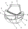
Fig. 16 is a diagram of a headgear assembly used with the interface assembly of fig. 2 prior to connection to the frame of the interface assembly of fig. 2.
Fig. 17 is a perspective view of an alternative interface assembly with the seal and clip separated from the frame.
Fig. 18 is a cross-sectional view of the interface assembly of fig. 17 taken along line 18-18 in fig. 17.
Fig. 19 is a cross-sectional view of the interface assembly of fig. 17 similar to fig. 18, with the seal and clip assembled to the frame.
Fig. 20 is a cross-sectional view of the seal and clip of the interface assembly of fig. 17 taken along line 20-20 in fig. 17.
Fig. 21 is a rear view of the frame of the interface package of fig. 17.
Fig. 22 is a front view of the frame of the interface package of fig. 17.
Figure 23 is a cross-sectional view of the frame of the interface package of figure 17 taken along line 23-23 in figure 21.
Detailed Description
An interface 20 arranged and configured in accordance with certain features, aspects and advantages of the present invention may provide improvements in, for example and without limitation, the delivery of CPAP therapy. In particular, the sealing interface 20 may exhibit improved sealing characteristics while limiting the pressure applied to the bridge of the nose of a user.
Overview of the System
It should be understood that the interface 20 may be used with any delivery device for respiratory care in general, including with a respirator, but the sealing interface 20 will be described with reference to use in a wet CPAP system. The delivery system may also be VPAP (variable positive airway pressure), BiPAP (bi-level positive airway pressure), or any other form suitable for use in respiratory therapy.
It should also be appreciated that the different features, aspects, and advantages of patient interface 20, although described in the context of a nasal mask, may be used with any other interface configuration, including, for example and without limitation, oral-nasal masks and full face masks that seal around the user's nose and mouth, oral masks that seal around the user's mouth, and nasal pillows or other types of masks that seal under the user's nose.
Referring to fig. 1, a wet Continuous Positive Airway Pressure (CPAP) system 22 is shown. The illustrated CPAP system 22 provides moist and pressurized gas to the user U through an interface 20 connected to a moist gas delivery path or inspiratory conduit 24.
The inspiratory conduit 24 is connected to an outlet 26 of a humidification chamber 30 that is adapted to contain a volume of water 32. Inspiratory conduit 24 may include, for example and without limitation, a heating arrangement (not shown), such as a heater wire. The heating arrangement may heat the walls of the inspiratory conduit 24 to reduce condensation of moisture gases within the inspiratory conduit 24.
The humidification chamber 30 is preferably formed of a plastic material and may have a highly thermally conductive substrate (e.g., an aluminum substrate) in direct contact with a heater plate 34 of a humidifier 36. The humidifier 36 employs a controller 40 or the like. The controller may comprise, for example and without limitation, a microprocessor-based controller that executes computer software commands stored in an associated memory.
The controller 40 receives input commands from a plurality of sources including a user input interface 42 (e.g., a dial). The user input interface 42 is capable of setting a predetermined value (e.g., a preset value) of the humidity, temperature or other characteristic of the gas supplied to the user U. The controller 40 may also receive input from other sources. For example, temperature and/or flow rate sensors 44, 46 connected by one connector 50 in the illustrated configuration may be in communication with the controller 40. In addition, a heater plate temperature sensor 52 may be in communication with the controller.
In response to a user-set humidity or temperature value, which may be input through the user interface 42, in combination with other inputs, the controller 40 determines when and/or at what level the heater plate 34 should be energized to properly heat the water 32 contained within the humidification chamber 30. As the volume of water 32 within the humidification chamber 30 is heated, water vapor begins to fill the volume above the surface of the water 32 in the humidification chamber 30. The water vapor exits the outlet 26 of the humidification chamber 30 with a flow of gas (e.g., air) provided from a gas supply 54 (e.g., a blower) and entering the humidification chamber 30 through an inlet 56.
The gas supply 54 preferably includes a gas flow generator 60, which may be a variable speed fan or may include a variable pressure regulator. In the illustrated configuration, the airflow generator 60 comprises a variable speed fan. The gas flow generator 60 preferably draws air or other gas through an inlet 62. The airflow generator 60 may be controlled by, for example, but not limited to, a controller 64 or may be controlled by the controller 40. The controller 64 may control the fan speed, regulated pressure, etc. according to any suitable criteria. For example, the controller 64 may be responsive to inputs from the controller 40 and a user setting (e.g., a preset value) of pressure and/or fan speed, which may be set using a user interface 66 (e.g., a dial).
Patient interface
Referring now to fig. 2 and 3, the interface 20 generally includes a mask assembly 100. The mask assembly 100 generally includes a frame 102, a seal 104, and a clip 106 for securing the seal 104 to the frame 102. The mask seal 104 and the clip 106 may be formed separately and secured together, or in some configurations, the mask seal 104 and the clip 106 may be integrated into a single assembly. In the configuration shown, the mask seal 104 is overmolded onto the mask seal clip 106. A connector 108 connects a breathing conduit (not shown) to the mask frame 102.
Referring now to fig. 4, the seal 104 is shown from the rear, which is the surface against the user's face. The seal 104 includes a face contacting surface 110. As shown in FIG. 4, the face contacting surface 110 preferably includes an edge 112 that at least partially defines an opening 114. In the configuration shown, the edge 112 encloses the opening 114. The opening 114 is designed to accommodate at least the lower portion and tip of the user's nose. Preferably, the opening 114 is generally T-shaped, although an inverted T-shape.
The face contacting surface 110 generally includes a lip surface 120 adapted to contact the user's face at a location above the lipped edge and below the nostrils. The face contacting surface 110 also includes two spaced-apart cheek surfaces 122 extending between the lip surface 120 of the face contacting surface 110 and a lateral surface 124 of the face contacting surface 110. Cheek surfaces 122 may contact a user's mid-cheek surface and/or a user's lateral nasal surface. Lateral surface 124 may extend over the nose of the user to connect the two cheek surfaces 122. Other configurations are possible.
As shown in the cross-sectional perspective view of fig. 5, the face-contacting surface 110 preferably comprises the thinnest cross-section of the material in the seal 104. Advantageously, the face-contacting surface 110 can be easily deformed to substantially seal against the contours of the user's face, including one or more of the upper lip, the middle of the cheeks, the sides of the nose, and the bridge of the nose. Advantageously, the thin cross-section of the face contacting surface 110 on the user's lips allows for increased stretchability and minimizes pressure applied to the area above the user's lips. The seal 104 may have any suitable configuration. In the illustrated embodiment, the seal 104 is inflatable. Thus, the pressure contained within the seal 104 may urge the face contacting surface 110 against the face of the user.
Referring again to fig. 4, the illustrated seal 104 also includes two thickened panels 130, which are shown in hidden lines. The panel 130 is generally positioned along an upper portion of the cheek surface 122, near the transition from the cheek surface 122 to the lateral surface 124. The face plate 130 may be formed on an inner surface of the seal 104. The panel 130 represents a locally thickened region that has been found to enhance the sealing ability of the seal 104. It is presently believed that the face plate 130 provides increased lateral pressure against the side surface of the user's nose, which allows the pressure from the seal 104 to better conform to the contour of the user's nose. In other words, the panel 130 may create a compression on the sides of the user's nose so that the pressure from the seal 104 better conforms to the contour of the user's nose.
Referring to fig. 5 and 6, the inner surface of the seal 104 further includes at least one thickened band 132. While a single thickened band 132 is shown in fig. 5 and 6, in some configurations, two or more thickened bands or thickened regions may be provided, taking into account the need to implement the features provided by the thickened band 132.
The thickened band 132 is shown positioned along one sidewall 134 of the seal 104. The sidewall 134 extends forward from the face contacting surface 110. The band 132 preferably includes a larger lower region 136 on the inside of each side of the seal 104 and a thinner connecting rib 140 that extends between the lower regions 136 by wrapping around the upper portion of the inside of the seal 104. Thickened band 132 helps to reduce the likelihood and/or extent of outward bulging of sidewall 134 as seal 104 receives pressure from system 22. The outward bulging of the sidewalls 134 may cause an undesirable change in the shape of the seal 104, which may adversely affect the performance of the seal 104.
Referring to fig. 5, the sidewall 134 preferably includes a thin-walled proximal portion 142 (i.e., proximal to the user's face) and a thin-walled distal portion 144 (i.e., distal to the user's face). Thin-walled proximal portion 142 is connected to thin-walled distal portion 144 with thickened band 132. Preferably, face contacting surface 110 forms a flange that curls inward from thin-walled proximal portion 142. More preferably, the face contacting surface 110 tapers away from the proximal portion 142 of the sidewall 134.
Still referring to fig. 5, the thin-walled distal portion 144 is crimped inwardly toward the clip 106 at a shoulder 146. In some configurations, thin-walled distal portion 144 is curled inward at shoulder 146 toward a rim 150. In the configuration shown, the rim 150 is overmolded with a portion of the clip 106.
The shoulder in combination with thin walled distal portion 144 and thickened band 132 allows seal 104 to exhibit a rolling action similar to that disclosed in the following patents: united states provisional patent application No. 61/476,188 filed on day 4/15 of 2011, 61/504,295 filed on day 7/4 of 2011, 61/553,067 filed on day 28 of 2011, 61/553,872 filed on day 31 of 2011, and international patent application No. PCT/IB2012/000858 filed on day 13 of 2012, which are incorporated herein by reference in their entirety. The rolling action is rather schematically represented in fig. 6 by a dash-dot line and indicated by the reference letter R. The distal part of the seal 104 can be rotated about a hinge point H while the most distal part will roll itself in the shoulder area as indicated by the roll-up portion R shown in dotted lines in fig. 6.
The tighter radius of thin walled distal portion 144 and shoulder 146 helps to allow controlled bending and rolling of seal 104. Further, when under pressure of the system 22, the internal pressure facilitates the rolling action by reducing the likelihood of the seal sticking to itself in the rolling region. Also, the reinforcing band 132 extends downward toward the hinge point H, but need not extend below the hinge point H. Reinforcing band 132 also acts as a limit to the extent thin walled distal portion 144 can be rolled and deformed. Thus, thin-walled distal portion 144 can only be rolled until thickened band 132 abuts rim 150.
Further, by having the thin-walled proximal portion 142 positioned between the reinforcement band 132 and the face-contacting surface 110, the thin-walled proximal portion 142 may deform slightly during donning of the mask assembly 100. Preferably, thin-walled proximal portion 142 can be deformed to some extent before thin-walled distal portion 144. The rolling effect provides an enhanced level of comfort for the user. Advantageously, the rolling effect allows the shape of the seal 104 to be changed to accommodate a wide range of nasal bridge heights while maintaining minimal change to load.
Referring to FIG. 7, a graphical depiction of test data is provided showing the differences provided by the rolling effect. Two shades, one from Fisher medical company&Paykel Healthcare) under the trademark ZestTMThe sold prior art nose mask compares to a technical prototype mask with a roll-up effect. The deformation of the mask in the nasal bridge region is shown as the force required to create the deformation. As shown, the technical prototype mask maintains a force well below 1.5N over the full range of deformation, whereas the prior art mask exceeds 4N over the same range of deformation. Moreover, as shown in FIG. 7, the technical prototype mask is much lower than the prior art mask at all deformation distances. Thus, the total force of the technical prototype mask from no displacement to full displacement is about 1N. Also, the increase in force experienced in the last 7mm (e.g., 13mm to 20mm displacement) displacement is less than about 0.3N.
Referring to fig. 17-23, an alternative embodiment of an interface package 100 includes a seal 104 having at least one lower thickened band 300 in addition to or in place of thickened band 132. The interface assembly 100 of fig. 17-23 is the same as or similar to the interface assembly 100 of fig. 2-16, except for at least one lower thickening band 300 and other features described below. Thus, in both embodiments, the same reference numerals are used to refer to the same or corresponding components or features. With particular reference to FIG. 20, a lower thickening band 300 is preferably provided in addition to thickening band 132. The lower thickened band 300 is positioned within a lower portion of the seal 104 and preferably within a lower half of the seal 104 and/or below the thickened band 132. Thickened band 300 is positioned along a lower portion of sidewall 134 of seal 104 and is preferably generally or substantially aligned in the fore-aft direction with thickened band 132. However, in other arrangements, the bands 132, 300 may be offset from each other in the fore-aft direction. In other alternative arrangements, a portion or all of thickened bands 132 and/or 300 may be arranged generally or substantially in a horizontal plane when seal 104 is in an upright position (as oriented in fig. 20). In some such arrangements, one or more thickening bands 132 and/or 300 may extend generally or substantially in the transverse direction of the seal 104. For example, a single thickened band 132 or 300 may be provided, which in some arrangements may be located generally or substantially at the midline of the seal 104. Alternatively, two or more thickened bands 132 or 300 may be provided, for example, which may be spaced above and below the midline of the seal 104. Further, a combination of one or more generally or substantially transverse bands and one or more generally or substantially vertical or circumferential bands may be provided.
The illustrated band 300 preferably includes a larger upper region 302 on the inside of each side of the seal 104 and a thinner connecting rib 304 extending between the larger upper regions 302. The upper region 302 and/or connecting ribs 304 are preferably generally similar in shape to the lower region 136 and ribs 140 of the band 132. However, in the arrangement shown, the band 300 is scaled down to a slightly smaller dimension than the band 132 to correspond with a lower portion of the seal 104 that is slightly thinner (in the fore-aft direction) than an upper portion of the seal 104. Preferably, the belt 300 performs substantially similar or identical functions as the belt 132. For example, the band 300 preferably reduces the likelihood and/or extent of outward bulging of the side walls 134 and causes a lower portion of the seal 104 to exhibit a rolling action in a manner similar or identical to that described above with respect to the band 132.
Referring now to fig. 8, three different cross-sections on a lower right portion of the illustrated seal 104 are illustrated. A lowermost cross-section near a corner of the illustrated seal 104 carries the reference letter a. One slightly higher section carries the reference letter B and one even higher section carries the reference letter C. As shown, the middle section B is substantially thicker than the two adjacent sections A, C. Although the three sections A, B, C are relatively close together, the large difference in thickness creates the ability to create a localized load against the user's face.
It is currently believed that the user's face may endure greater loads or stresses in certain areas than in others. By increasing the thickness of the side walls 134, the force may be better transmitted from the clip 106 to the face contacting surface 110 through the side walls 134. Similarly, the reduced thickness of the side walls 134 allows less force to be transmitted between the clip 106 and the face-contacting surface 110 through the side walls. In some configurations, it is believed that the user's face may better tolerate pressure in the maxillary region just below the zygomatic process. For this reason, the lower corner region 152 includes a region of increased thickness (e.g., portion B). When connected with a forehead contact point provided by the frame 102, a triangular support may be defined between the two lower regions 152 of the seal 104 and the forehead contact point. The triangular support provides a stable platform on the face that can help resist movement during use.
To permanently attach the seal 104 to the clip 106, overmolding may be used. Referring to fig. 9, the clip 106 is shown without the seal 104 attached. The clip 106 may be formed of any suitable rigid or semi-rigid material. In one configuration, the clip 106 is formed from a polycarbonate material. Because the seal 104 is preferably formed of a silicone material and because the clip 106 is formed of a polycarbonate material, a retention structure 160 has been provided on the clip 106 to allow the seal 104 to be secured and overmolded to the clip 106. In other words, the silicone material of the seal 104 generally does not adhere to the polycarbonate material of the clip 106, thus retaining the seal 104 on the clip 106 by positively locking the silicone material around features of the retaining structure 160.
The retaining structure 160 of the clip 106 is formed at a proximal end 162 of the clip 106. Although the retaining structure 160 is shown as being integrally formed with the clip 106, the two may be separately formed and secured together in any suitable manner. However, the integrated construction provides improved manufacturability and a more durable finished product.
The retaining structure 160 includes a plurality of posts 164 defining a plurality of slots 166. Preferably, the posts 164 are spaced about a peripheral surface 168 that defines an opening 170 at the proximal end of the clip 106. More preferably, the posts 164 are substantially equally spaced about the peripheral surface 168. Even more preferably, the posts 164 are spaced about the peripheral surface 168 such that a ratio of approximately 1:2 is defined between the posts 164 and the intermediate slots 166. A ratio of 1:2 has been found to maximize the strength of the connection between the seal 104 and the clip 106.
With continued reference to fig. 9 and 10, the retaining structure 160 preferably includes at least one distal surface 172 and at least one proximal surface 174 that are generally parallel to one another. In the illustrated configuration, the at least one distal surface 172 comprises an annular surface that encompasses the proximal end 162 of the clip 106, while the at least one proximal surface 174 comprises the ends of the posts 164. The parallel surfaces 172, 174 help to minimize compression and distortion due to clamping forces experienced during the overmolding process.
Moreover, as shown in fig. 9 and 10, the slot 166 is generally sealed by a ring 176. In the illustrated configuration, the ring 176 encircles the exterior of the post 164 at the distal end of the post 164. Other configurations may also be possible. However, the configuration shown makes the manufacturing configuration simple.
Referring to fig. 10, a distal portion 180 of the clip 106 is configured to be mounted to the frame 102. Preferably, the clip 106 is easily mounted to the frame 102 and easily removed from the frame 102, such that cleaning of the clip 106 and the attached seal 104 may be facilitated. More preferably, the distal portion 180 is adapted to seal with a surface of the frame 102. Even more preferably, a distal surface 182 is adapted to seal against a surface of the frame 102.
Still referring to fig. 10, the distal portion 180 of the clip 106 includes one or more recesses 184. Preferably, the recess 184 is also designed to seal with the frame 102. Specifically, the low-profile frame 102 includes one or more protrusions 190 extending rearward toward the clip 106. To provide a tight fit and reduce the profile of the assembly 100, the recesses 184 in the clip 106 advantageously accommodate these protrusions.
Referring to fig. 3 and 11, the frame 102 and clip 106 are preferably coupled together in an airtight or sealed relationship. In the illustrated configuration, the frame 102 includes a mounting boss 192 that extends toward the clip 106. The mounting boss 192 includes an outer surface 194 on which an inner surface 196 of the distal portion 180 of the clip 106 slides. Preferably, the connection between the bump 192 and the distal portion 180 of the clip 106 is a tapered fit. More preferably, the connection comprises a 1:40 medical taper providing a sealing surface to minimize leakage between the two components. Even more preferably, the tapered connection includes an interference fit wherein the travel is 2mm as measured from the rear face 200 of the frame 102 to the distal surface 182 of the clip 106. While the outer surface 194 of the illustrated protuberance 192 and the inner surface 196 of the illustrated distal portion 180 are generally cylindrical, other shapes are possible.
Referring to fig. 17-23, the alternative interface assembly 100 includes an improvement in a removable mounting arrangement between the clip 106 and the frame 102. Specifically, the mounting boss 192 includes a wall portion that is discontinuous or discontinuous about its circumference. Preferably, a proximal end (i.e., near the user) includes at least one and preferably a plurality of recesses or grooves 310 that extend toward a distal end of the mounting boss 192 to facilitate attachment of the clip 106 to the frame 102. Specifically, grooves 310 cause the wall portions of ridges 192 to flex inwardly between grooves 310 to effectively reduce the diameter of mounting ridges 192 during assembly of clip 106 to frame 102. In the illustrated arrangement, the grooves 310 are generally or substantially triangular in shape and four grooves 310 are provided. However, other shapes (e.g., generally or substantially rectangular, square, trapezoidal, semi-circular) and numbers (e.g., 2, 3, 5, 6, or more) of grooves 301 may be used. Further, preferably, the grooves 310 are unevenly spaced about the circumference of the mounting boss 192. In the illustrated arrangement, the grooves 310 are arranged in an upper pair and a lower pair, wherein the circumferential distance between the individual grooves 310 of the upper and lower pair is less than the circumferential distance between one groove 310 of the upper pair and the adjacent groove 310 of the lower pair. Preferably, in other respects, the mounting bosses 192 of the interface package 100 of fig. 17-23 are similar to the mounting bosses 192 of the interface package 100 of fig. 2-16, including, for example, a tapered fit.
The clip 106 and frame 102 of fig. 17-23 preferably also include an interference or interlock arrangement 320 that helps maintain the connection between the clip 106 and the frame 102 and/or increases the force required to detach the clip 106 from the frame 102. This arrangement desirably reduces the likelihood of inadvertent or undesired separation of the clip 106 from the frame 102. Preferably, one of the clip 106 and the frame 102 includes at least one protrusion, while the other of the clip 106 and the frame 102 includes at least one recess sized and shaped to receive the protrusion. In the illustrated arrangement, the clip 106 includes a pair of protrusions 322, while the frame 102 includes a pair of complementary recesses 324; however, this arrangement may also be reversed. Preferably, the protrusions 322 are positioned at the top and bottom of the inner surface 196 of the distal portion 180 of the clip 106, while the recesses 324 are positioned at the top and bottom of the outer surface 194 of the mounting boss 192 of the frame 102. In the illustrated arrangement, the protrusion 322 and recess 324 are diametrically opposed to each other and are each elongated in the circumferential direction of the corresponding surfaces 196 and 194 to maximize the length of the interference or interlocking surfaces that tend to inhibit separation of the frame 102 and clip 106 and minimize the length in the axial direction.
Preferably, the frame 102 of the interface assembly 100 of fig. 17-23 includes at least one recess 330 that, in use, receives the distal portion 180 of the clip 106. In the illustrated arrangement, the frame 102 includes a pair of recesses 330 positioned on opposite sides of the mounting boss 192 and that interact with the clip 106 to inhibit or prevent the clip 106 from rotating relative to the frame 102. Preferably, the lower end of the depression 330 is located proximate the mounting protuberance 192, while the upper end of the depression 330 extends laterally outward away from the mounting protuberance 192. At least a portion of the circumference of the distal portion 180 of the clip 106 of fig. 17-23 has a smaller wall thickness than the clip 106 of fig. 2-16. The clip 106 of fig. 17-23 transitions at a shoulder 332 to a greater wall thickness portion that defines a distal facing surface 334. Preferably, as shown in fig. 19, surface 334 contacts one end surface 336 of recess 330 in addition to distal surface 182 contacting frame 102 to help form a seal between clip 106 and frame 102. In addition, the contact between the surface 334 and the end surface 336 may define a fully connected position between the clip 106 and the frame 102. The shoulder 332 may be defined by the recess 184 of the clip 106, and thus may be coextensive with the recess 184. The engagement of the recess 184 with the recess 330 may inhibit or prevent the clip 106 from rotating relative to the frame 102. In other arrangements, the shoulder 332 may encircle a greater distance than the recess 184 or a single shoulder 332 may encircle the entire distal portion 180.
Referring to fig. 3 and 11, the protuberance 192 preferably encloses an inner surface that defines a socket 202 for a ball fitting 204 of the connector 108. In the illustrated configuration, the connector 108 generally includes an elbow 206 and a swivel 210. The swivel joint 210 may be used to connect to an inspiratory conduit 24 or other breathing tube. Preferably, the elbow 206 is connected to the frame 102 by a joint defined by the ball 204 and socket 202, and the swivel 204 is connected to the elbow with a cantilevered tab arrangement 212.
The engagement defined by the ball 204 and socket 202 preferably enables a limited range of rotational movement. In some configurations, the ball 204 may rotate up to about 30 degrees relative to the socket 202. Other ranges of rotational movement may also be defined as necessary.
In the illustrated configuration, the ball 204 is pressed into the socket 202 of the frame 102. In other words, the bend 206 enters through the socket 202 and the ball 204 is pressed into engagement with the socket 202. In this configuration, elbow 206 is less likely to be easily removed from frame 102 by a user.
Swivel joint 210, on the other hand, is designed to be easily removed from elbow 206. Preferably, the swivel joint 210 is fully rotatable about its axis relative to the elbow 206 and as little as about 30N of the swivel joint 210 may be usedThe force is removed axially from the bend 206. Also, the connection between the elbow 206 and the swivel 210 is preferably designed to reduce leakage at the connection. In the configuration shown, the leakage is at 10cm H2Maintained at less than about 0.05 to about 0.4L/min under O.
Referring to fig. 3, a distal end 214 of the bend 206 preferably includes two or more cut-out regions or depressions 216. The recess 216 may have any suitable shape, and in the illustrated configuration, the recess 216 comprises a semi-circular configuration that extends upwardly into the distal end 214 of the elbow 206. The distal end 214 of the bend 206 also includes at least one tab 220, and preferably two or more tabs 220. Preferably, each of the tabs 220 extends around an arc of about 70 degrees. More preferably, each of the bumps 220 is generally centered in two of the recesses 216, and each of the bumps 220 extends about 70 degrees around an outer surface of the distal end 214 of the bend 206.
The rotary joint 210 is preferably generally cylindrical in configuration. As shown in fig. 3, the swivel joint 210 has an inwardly extending ridge 222. The ridge 222 preferably circumscribes the entire inner surface. In some configurations, the ridges 222 may be interrupted. Preferably, however, the ridge 222 does not have any interruption large enough to accommodate the entire tab 220, such that the ridge 222 and the tab 220 can cooperate to keep the swivel 210 mounted on the distal end 214 of the elbow 206. When the swivel 210 is assembled to the elbow 206, the depression 216 deflects the tab 220 inwardly so that the tab 220 can slide over the ridge 222 and then snap back outwardly to secure the tab 220 under the ridge 222. For this reason, the distance from a shoulder 224 (see fig. 12) to the top of the tab 220 (shown as X in fig. 12) is substantially equal to or slightly greater than the distance from a proximal end 226 (see fig. 3) of the swivel to the bottom edge of the ridge 220.
Referring now to fig. 12, elbow 206 preferably includes a plurality of integrally formed exhaust holes 230. While the vent 230 may be formed on a separate insert that is secured to the elbow 206, integrally forming the vent 230 provides a cleaner aesthetic appearance and provides for simplified assembly of the interface assembly 100. The vent hole is preferably formed on one surface of the elbow 206 that is on the outside of the turn from the proximal end with the ball 204 toward the distal end 214. Other configurations are possible.
Referring to fig. 13, the vent 230 preferably comprises a two-part configuration. A proximal end 232 of the one or more vent holes 230 forms a conical recess into an inner surface 234. In other words, the proximal end 232 of one or more vent holes 230 includes a countersunk surface. A distal end 236 of the one or more exhaust apertures 230 includes a flared surface. In other words, the distal end of the one or more vent holes 230 comprises a portion of an hourglass shape. Preferably, the conical shape of the proximal end 232 and the flared shape of the distal end 236 are generally axially aligned and have a smooth transition between the two shapes. More preferably, all or substantially all of the exhaust holes 230 have this configuration. Even more preferably, the axial centerlines of all or substantially all of the exhaust holes 230 are generally parallel to each other.
With continued reference to fig. 13, the proximal end 232 of the vent hole 230 preferably defines a conical surface that is substantially parallel to an axial centerline CL of the proximal end of the elbow when viewed in cross-section. In other words, the axial centerline CL is generally related to the direction in which a mold or insert is inserted and removed during manufacture. More preferably, the proximal end 232 of the vent has at least one sidewall (when viewed in cross-section) that will extend generally parallel (see reference line PL) or generally obliquely relative to parallel when viewed in cross-section, such that the surface extends away from parallel when moved in the proximal direction (i.e., when the proximal end 232 is expanded). In this manner, all or a substantial portion of the proximal end 232 of the vent hole 230 may be formed from a single insert, while allowing for easy withdrawal of the insert. In some configurations, an insert or mold may be withdrawn through the distal end 214 of the elbow and the vent holes 230, and the vent holes 230 have surfaces appropriately configured for the direction of insertion and removal of such an insert.
Preferably, the wall thickness (i.e., the distance between the inner surface 234 and the outer surface 240) is approximately 1.5 mm. In this configuration, the proximal end 232 (i.e., the conical portion in fig. 14) is approximately 0.5mm, while the distal end 236 (i.e., the flared portion in fig. 14) is approximately 1.0 mm. Other sizes and configurations are possible. The configuration shown has been found to suitably reduce the noise level associated with the air flow exiting the exhaust vent 230.
Referring again to fig. 2, one or more headgear clips 250 are shown attached to the frame 102. In the configuration shown, two headgear clips 250 are secured to the frame 102. The frame 102 generally includes an ear 252 associated with each headgear clip 250. The ear 252 preferably extends generally laterally outward from the inner surface of the socket 202 defining the elbow 206.
As illustrated in fig. 15, each of the ears 252 includes a post 254, while each clip 250 includes a hook 256. The hook 256 and post 254 provide an easily connectable and disconnectable arrangement. Preferably, the clips 250 are symmetrical so that a single clip can be used on both the left and right sides of the frame 102.
In some configurations, a slight interference may be provided between the hook 256 and the post 254, making the hook 256 less likely to inadvertently become disengaged during use. In some configurations, the hook 256 and post 254 can be shaped such that the hook 256 is easier to disengage upward at certain angles around the post 254 (e.g., rotating the hook 256 around the post 254 and away from the seal 106 can allow easier disengagement due to the profile of the post 254). Also, because the hook 256 is able to rotate relative to the post 254, the angular orientation of the clip 250 relative to the frame 102 can be changed so that different head shapes can be easily accommodated.
Each clip 250 includes a slot 260 defined through the entire body 262 of the clip 250. Slot 260 is sized and configured to receive a lower strap 264 of a headgear assembly 266. Preferably, lower strap 264 is looped through slot 260 and folded back on itself. More preferably, lower strap 264 includes a hook and loop fastener portion such that lower strap 264 is looped through slot 260, folded back on itself and secured to itself. Other configurations may also be used.
The headgear assembly 266 also includes a pair of top straps 270 and a pair of upper straps 272. Top strap 270, upper strap 272, and bottom strap 264 preferably meet at a central body 274. Moreover, each of straps 264, 270, 272 preferably terminates in a projection 276, which may form part of a hook and loop fastener. The projections 276 may be ultrasonically welded to the ends of the straps 264, 270, 272.
The top strap 270 may be connected with a latch that will generally rest on top of the head. When combined with the fastener, the top strap 270 generally defines a crown strap. Upper straps 272 are looped through slots 280 (see fig. 2) formed in one t-shaped tube portion of frame 102 and lower straps 264 are looped through clip 250 as described above. In some configurations, slot 280 in the t-tube portion of frame 102 has an interruption in the material defining slot 280, such that the loop defined by upper strap 272 can be attached and detached from frame 102 without requiring protrusion 276 to be detached from the portion of strap 272 that is attached to protrusion 276 with a hook and loop fastener.
In the alternative interfacing arrangement 100 of fig. 17-23, the slot 280 defines an opening 340 at a bottom end of the slot 280 and has a closed end 342 at a top end thereof. Specifically, one central portion 344 of the frame 102 extends along the inside of the slot 280 and transitions into an upper portion 346 that defines the closed end 342 of the slot 280. The outer portion 350 extends along the outside of the slot 280 and terminates in an inwardly extending projection 352 that extends toward the central portion 344 but stops a short distance therefrom to define the opening 340 of the slot 280. The upper closed end 342 prevents the upper strap 272 from disconnecting in an upward direction from the frame 102, while the tab 352 inhibits the upper strap 272 from unintentionally or undesirably disconnecting in a downward direction from the frame 102.
In the configuration shown, lower strap centerline LS intersects at a location between main body 274 and upper strap centerline US. In some configurations, lower strap centerline LS intersects the same side of upper strap centerline US as lower strap 264 is positioned. In some configurations, the intersection of the lower strap centerline LS is offset from the upper strap centerline US by a distance N. Preferably, the distance N is about 23 mm. In some configurations, lower strap centerline LS intersects upper strap centerline US at a location spaced apart by distance M. Preferably, the distance M is about 43 mm. Other configurations are also possible.
Although the present invention has been described with respect to a certain embodiment, other embodiments apparent to those of ordinary skill in the art are also within the scope of the present invention. Accordingly, various changes and modifications may be made without departing from the spirit and scope of the invention. For example, different components may be repositioned as desired. Moreover, not all features, aspects, and advantages may be required to practice the present invention. Accordingly, the scope of the invention is intended to be defined only by the following claims.
Claims (24)
1. A seal member for an interface assembly, the seal member comprising:
a side wall;
a flange extending inwardly from the sidewall, the flange including a face contacting surface, the face contacting surface including:
an edge at least partially defining an opening;
a first buccal surface; and
a second cheek surface configured to contact a mid-cheek surface and/or a side surface of a respective side of the nose of the patient in use; and
a first thickened panel and a second thickened panel,
wherein the first and second thickened panels comprise locally thickened regions of the first and second cheek surfaces, each of the thickened panels extending from or from about a respective portion of the rim.
2. The seal member of claim 1, wherein first and second thickened panels are formed on an inner surface of the seal member.
3. The seal member of claim 1, wherein first and second thickened panels do not extend to the sidewall of the seal member.
4. The sealing member of claim 1, wherein the sidewall includes a first thin-walled portion at a proximal portion of the sealing member relative to the flange and a second thin-walled portion at a distal portion of the sealing member relative to the flange.
5. The seal member of claim 4, wherein the second thin wall portion is curled inwardly toward the rim at a shoulder.
6. The sealing member of claim 1, wherein a portion of the sealing member is rotatable about a hinge point and/or is configured to roll itself up.
7. The sealing member of any preceding claim, wherein an inner surface of the sealing member comprises a first thickened band extending along the sidewall.
8. The seal member of claim 7, wherein:
the first thickened band is located in an upper portion of the sealing member, the upper portion including a nose bridge portion.
9. The seal member of claim 7, wherein the first thickened band includes first and second lower regions and a connecting rib extending between the first and second lower regions, the connecting rib being thinner than the first and second lower regions and wrapping around an upper portion of the inside of the seal member.
10. The sealing member of claim 7, comprising a second thickened band in a lower portion of the sealing member.
11. The seal member of claim 4, comprising:
a first thickening band in an upper portion of the sealing member, the upper portion including a nose bridge portion; and
a second thickening band located in a lower portion of the sealing member,
wherein the first and second thin wall portions are connected to the first thickened band.
12. The seal member of claim 1, wherein the seal member is configured to be connected to a clip member.
13. An interface assembly, comprising:
a frame; and
the sealing member according to any one of claims 1-6 connected to the frame.
14. The interface assembly according to claim 13, including a mask sealing clip securing the sealing member to the frame and having increased rigidity relative to the sealing member.
15. The interface assembly of claim 14, wherein the sealing member covers at least a portion of the mask sealing clip when a portion of the sealing member is rolled.
16. The interface assembly of claim 13, wherein a portion of the sealing member is overmolded onto a clip member.
17. The interface assembly of claim 16, wherein:
the side wall of the sealing member includes a first thin-walled portion and a second thin-walled portion, the first thin-walled portion being located at a proximal end portion of the sealing member with respect to the flange, and the second thin-walled portion being located at a distal end portion of the sealing member with respect to the flange,
the second thin-walled portion is curled inward toward the rim at a shoulder portion, and
the rim is overmolded with a portion of the clip member.
18. The interface assembly of claim 17, wherein the clip member includes a feature that receives a complementary feature of the frame.
19. The interface assembly of claim 17, wherein the clip member tapers from a larger configuration at a proximal end of a seal member to a smaller configuration at a distal end of a seal member.
20. The interface assembly of claim 13, wherein the inner surface of the sealing member includes a first thickened band disposed along the sidewall.
21. The interface assembly of claim 20, wherein:
the first thickened band is located in an upper portion of the sealing member, the upper portion including a nose bridge portion.
22. The interface assembly of claim 20, wherein the first thickening band includes first and second lower regions and a connecting rib extending between the first and second lower regions, the connecting rib being thinner than the first and second lower regions and wrapping around an upper portion inside a sealing member.
23. The interface assembly of claim 20, comprising a second thickened band in a lower portion of the sealing member.
24. The interface assembly of claim 17, comprising:
a first thickening band in an upper portion of the sealing member, the upper portion including a nose bridge portion; and
a second thickening band located in a lower portion of the sealing member,
wherein the first and second thin wall portions are connected to the first thickened band.
Applications Claiming Priority (3)
| Application Number | Priority Date | Filing Date | Title |
|---|---|---|---|
| US201161504061P | 2011-07-01 | 2011-07-01 | |
| US61/504,061 | 2011-07-01 | ||
| CN201280040172.0A CN103732281B (en) | 2011-07-01 | 2012-06-29 | Nose cup interface package |
Related Parent Applications (1)
| Application Number | Title | Priority Date | Filing Date |
|---|---|---|---|
| CN201280040172.0A Division CN103732281B (en) | 2011-07-01 | 2012-06-29 | Nose cup interface package |
Publications (2)
| Publication Number | Publication Date |
|---|---|
| CN107469210A CN107469210A (en) | 2017-12-15 |
| CN107469210B true CN107469210B (en) | 2021-02-02 |
Family
ID=47421843
Family Applications (5)
| Application Number | Title | Priority Date | Filing Date |
|---|---|---|---|
| CN201710583278.XA Active CN107469208B (en) | 2011-07-01 | 2012-06-29 | Nasal mask interface assembly |
| CN201280040172.0A Active CN103732281B (en) | 2011-07-01 | 2012-06-29 | Nose cup interface package |
| CN201710583293.4A Active CN107469209B (en) | 2011-07-01 | 2012-06-29 | Nasal mask interface assembly |
| CN201710583294.9A Active CN107469218B (en) | 2011-07-01 | 2012-06-29 | Nasal mask interface assembly |
| CN201710583295.3A Active CN107469210B (en) | 2011-07-01 | 2012-06-29 | Nasal mask interface assembly |
Family Applications Before (4)
| Application Number | Title | Priority Date | Filing Date |
|---|---|---|---|
| CN201710583278.XA Active CN107469208B (en) | 2011-07-01 | 2012-06-29 | Nasal mask interface assembly |
| CN201280040172.0A Active CN103732281B (en) | 2011-07-01 | 2012-06-29 | Nose cup interface package |
| CN201710583293.4A Active CN107469209B (en) | 2011-07-01 | 2012-06-29 | Nasal mask interface assembly |
| CN201710583294.9A Active CN107469218B (en) | 2011-07-01 | 2012-06-29 | Nasal mask interface assembly |
Country Status (9)
| Country | Link |
|---|---|
| US (4) | US10653854B2 (en) |
| EP (4) | EP2726132B1 (en) |
| JP (5) | JP6227528B2 (en) |
| CN (5) | CN107469208B (en) |
| AU (5) | AU2012278416B2 (en) |
| ES (1) | ES2704823T3 (en) |
| FR (2) | FR2977164B1 (en) |
| GB (5) | GB2563704B (en) |
| WO (1) | WO2013006065A1 (en) |
Families Citing this family (62)
| Publication number | Priority date | Publication date | Assignee | Title |
|---|---|---|---|---|
| USD695887S1 (en) | 2010-09-10 | 2013-12-17 | Resmed Limited | Respiratory mask |
| EP3231470B1 (en) | 2010-09-30 | 2023-01-11 | ResMed Pty Ltd | Mask system |
| AU2011342900A1 (en) | 2010-12-17 | 2013-07-18 | Intellijoint Surgical Inc. | Method and system for aligning a prosthesis during surgery |
| US10603456B2 (en) | 2011-04-15 | 2020-03-31 | Fisher & Paykel Healthcare Limited | Interface comprising a nasal sealing portion |
| GB2532395B (en) | 2011-04-15 | 2016-07-06 | Fisher & Paykel Healthcare Ltd | Interface comprising a rolling nasal bridge portion |
| JP6227528B2 (en) | 2011-07-01 | 2017-11-08 | フィッシャー アンド ペイケル ヘルスケア リミテッド | Nasal mask interface assembly |
| USD693459S1 (en) | 2011-09-16 | 2013-11-12 | Fisher & Paykel Healthcare Limited | Patient interface assembly |
| US9867958B2 (en) * | 2012-04-20 | 2018-01-16 | Koninklijke Philips N.V. | Auto-adjusting membrane for respiratory interface device |
| WO2014038959A1 (en) | 2012-09-04 | 2014-03-13 | Fisher & Paykel Healthcare Limited | Valsalva mask |
| US10589046B2 (en) | 2012-10-17 | 2020-03-17 | Fisher & Paykel Healthcare Limited | Interface comprising a nasal sealing portion and a rolling hinge |
| US10821250B2 (en) | 2012-11-16 | 2020-11-03 | Fisher & Paykel Healthcare Limited | Nasal seal and respiratory interface |
| US20140166016A1 (en) * | 2012-12-14 | 2014-06-19 | Hsiner Co., Ltd. | Respiratory Mask |
| WO2014110626A1 (en) * | 2013-01-16 | 2014-07-24 | Resmed Limited | Patient interface and method for making same |
| JP6921916B2 (en) * | 2013-01-16 | 2021-08-18 | レスメド・プロプライエタリー・リミテッド | Patient interface and methods for forming the patient interface |
| NZ714593A (en) | 2013-04-12 | 2017-08-25 | Resmed Ltd | Neck strap, crown strap assembly and headgear for a breathing mask |
| CN105722544B (en) | 2013-11-11 | 2018-01-19 | 皇家飞利浦有限公司 | Snap-in bend pipe for patient interface mask |
| CN106029144B (en) | 2013-11-15 | 2018-06-12 | 瑞思迈有限公司 | Patient interface and the method for manufacturing it |
| EP3079745B1 (en) | 2013-12-11 | 2019-12-11 | Fisher & Paykel Healthcare Limited | Respiratory interface |
| GB2521644B (en) | 2013-12-24 | 2020-03-11 | Intersurgical Ag | Improvements relating to respiratory masks |
| CN110876828A (en) | 2014-06-17 | 2020-03-13 | 费雪派克医疗保健有限公司 | Patient interface |
| CN104107494B (en) * | 2014-07-23 | 2016-08-24 | 李涛平 | A kind of nasal mask of band nasogastric tube passage |
| AU2015307325A1 (en) * | 2014-08-25 | 2017-04-06 | Fisher & Paykel Healthcare Limited | Respiratory mask and related portions, components or sub-assemblies |
| CN104208789B (en) * | 2014-09-01 | 2018-05-29 | 北京怡和嘉业医疗科技股份有限公司 | Breathing mask |
| WO2016119018A1 (en) | 2015-01-30 | 2016-08-04 | Resmed Asia Operations Pty Limited | Patient interface comprising a gas washout vent |
| CN107530518B (en) * | 2015-03-04 | 2020-09-08 | 费雪派克医疗保健有限公司 | Mask system head-wearing tool |
| WO2016157040A1 (en) * | 2015-03-27 | 2016-10-06 | Fisher & Paykel Healthcare Limited | Patient interface and aspects thereof |
| US10716912B2 (en) | 2015-03-31 | 2020-07-21 | Fisher & Paykel Healthcare Limited | User interface and system for supplying gases to an airway |
| CN104906676B (en) * | 2015-06-23 | 2017-11-14 | 北京怡和嘉业医疗科技股份有限公司 | A kind of face shield assembly |
| WO2017042717A1 (en) * | 2015-09-11 | 2017-03-16 | Fisher & Paykel Healthcare Limited | Nasal seal, mask and respiratory interface assembly |
| EP4043057B1 (en) * | 2015-09-23 | 2024-01-03 | ResMed Pty Ltd | Patient interface with a seal-forming structure having varying thickness |
| EP3352828B1 (en) * | 2015-09-23 | 2022-06-01 | ResMed Pty Ltd | Patient interface with a seal-forming structure having varying thickness |
| NZ780421A (en) * | 2015-09-23 | 2024-07-05 | ResMed Pty Ltd | Patient interface with a seal-forming structure having varying thickness |
| USD782031S1 (en) * | 2015-09-25 | 2017-03-21 | Fisher & Paykel Healthcare Limited | Face mask cushion and frame assembly |
| USD784516S1 (en) | 2015-09-25 | 2017-04-18 | Fisher & Paykel Healthcare Limited | Face mask frame |
| USD782030S1 (en) | 2015-09-25 | 2017-03-21 | Fisher & Paykel Healthcare Limited | Face mask |
| USD800895S1 (en) * | 2015-09-25 | 2017-10-24 | Fisher & Paykel Healthcare Limited | Face mask cushion |
| USD828917S1 (en) | 2015-09-25 | 2018-09-18 | Fisher & Paykel Healthcare Limited | Vent diffuser |
| USD784515S1 (en) | 2015-09-25 | 2017-04-18 | Fisher & Paykel Healthcare Limited | Headgear |
| USD790054S1 (en) * | 2015-09-25 | 2017-06-20 | Fisher & Paykel Healthcare Limitied | Swivel connector |
| SG10202010420TA (en) | 2016-04-22 | 2020-11-27 | Fisher & Paykel Healthcare Ltd | Patient interface and aspects thereof |
| USD882066S1 (en) | 2016-05-13 | 2020-04-21 | Fisher & Paykel Healthcare Limited | Frame for a breathing mask |
| US11324908B2 (en) | 2016-08-11 | 2022-05-10 | Fisher & Paykel Healthcare Limited | Collapsible conduit, patient interface and headgear connector |
| WO2018064712A2 (en) | 2016-10-04 | 2018-04-12 | Resmed Asia Operations Pty Ltd | Patient interface with movable frame |
| USD823455S1 (en) | 2017-02-23 | 2018-07-17 | Fisher & Paykel Healthcare Limited | Cushion assembly for breathing mask assembly |
| USD823454S1 (en) | 2017-02-23 | 2018-07-17 | Fisher & Paykel Healthcare Limited | Cushion assembly for breathing mask assembly |
| USD824020S1 (en) | 2017-02-23 | 2018-07-24 | Fisher & Paykel Healthcare Limited | Cushion assembly for breathing mask assembly |
| USD901673S1 (en) | 2017-03-09 | 2020-11-10 | Fisher & Paykel Healthcare Limited | Frame and breathing tube assembly for a nasal mask |
| USD874646S1 (en) | 2017-03-09 | 2020-02-04 | Fisher & Paykel Healthcare Limited | Headgear component for a nasal mask assembly |
| USD875242S1 (en) | 2017-09-20 | 2020-02-11 | Fisher & Paykel Healthcare Limited | Nasal mask and breathing tube set |
| USD855793S1 (en) | 2017-09-20 | 2019-08-06 | Fisher & Paykel Healthcare Limited | Frame for a nasal mask |
| ES2877713T3 (en) * | 2017-10-11 | 2021-11-17 | Air Liquide Medical Systems | Respirator with rotating elbow connector and cover |
| AU2019231515A1 (en) * | 2018-03-07 | 2020-10-15 | Fisher & Paykel Healthcare Limited | Patient interface |
| US11679220B2 (en) * | 2018-04-12 | 2023-06-20 | Loewenstein Medical Technology S.A. | Mask bead |
| TWI737934B (en) * | 2018-09-14 | 2021-09-01 | 雃博股份有限公司 | Respiratory mask |
| WO2020079617A1 (en) * | 2018-10-16 | 2020-04-23 | ResMed Pty Ltd | Patient interface |
| USD892307S1 (en) * | 2018-12-29 | 2020-08-04 | Bmc Medical Co., Ltd. | Patient interface |
| JPWO2020217798A1 (en) * | 2019-04-23 | 2021-12-23 | 株式会社村田製作所 | CPAP device |
| US11819612B2 (en) | 2019-10-10 | 2023-11-21 | Fisher & Paykel Healthcare Limited | Respiratory mask system |
| US11426551B1 (en) * | 2020-06-23 | 2022-08-30 | Lisa M. Butler, Esquire | Nasal ventilation mask |
| GB2597515A (en) * | 2020-07-24 | 2022-02-02 | Flexicare Group Ltd | Nasal Cannula |
| WO2022051336A1 (en) * | 2020-09-01 | 2022-03-10 | Arizona Board Of Regents On Behalf Of Arizona State University | Device and method for mitigating aerosol release from nebulization or respiratory system |
| JP7564026B2 (en) * | 2021-03-12 | 2024-10-08 | 日本光電工業株式会社 | mask |
Citations (9)
| Publication number | Priority date | Publication date | Assignee | Title |
|---|---|---|---|---|
| CN1681553A (en) * | 2002-09-06 | 2005-10-12 | 雷斯梅德有限公司 | Cushion for a respiratory mask assembly |
| WO2006074513A1 (en) * | 2005-01-12 | 2006-07-20 | Resmed Limited | Cushion for patient interface |
| AU2006284507A1 (en) * | 2005-08-22 | 2007-03-01 | Compumedics Limited | Mask assembly |
| WO2007145534A1 (en) * | 2006-06-16 | 2007-12-21 | Fisher & Paykel Healthcare Limited | Breathing assistance apparatus |
| CN101119763A (en) * | 2005-01-12 | 2008-02-06 | 雷斯梅德有限公司 | Reinforcement for patient interface |
| CN101861180A (en) * | 2007-11-15 | 2010-10-13 | 雷斯梅德有限公司 | a buffer structure |
| CN101954140A (en) * | 2002-06-14 | 2011-01-26 | Map医药-技术有限责任公司 | Mask cushioning and forehead pad for a respiratory mask, respiratory mask, manufacturing mould and method for producing the same |
| CN102046233A (en) * | 2008-05-29 | 2011-05-04 | 雷斯梅德有限公司 | Flexible structure for mask, and method and apparatus for evaluating performance of a mask in use |
| WO2011077254A2 (en) * | 2009-12-23 | 2011-06-30 | Fisher & Paykel Healthcare Limited | Patient interface and headgear |
Family Cites Families (164)
| Publication number | Priority date | Publication date | Assignee | Title |
|---|---|---|---|---|
| US2228218A (en) | 1936-11-25 | 1941-01-07 | Hygeia Filtering Corp | Respirator |
| US2415846A (en) | 1944-10-23 | 1947-02-18 | Randall Francis Eugene | Oronasal mask |
| US3037501A (en) * | 1959-02-02 | 1962-06-05 | Scott Aviation Corp | Quick-donning breathing mask |
| US4167185A (en) | 1977-04-18 | 1979-09-11 | A-T-O Inc. | Face mask seal |
| US4384577A (en) | 1981-04-03 | 1983-05-24 | Moldex/Metric Products, Inc. | Disposable face mask |
| WO1992000120A1 (en) * | 1990-06-26 | 1992-01-09 | Cam Lock (Uk) Ltd. | Improved breathing equipment for aircrew |
| FR2682043A1 (en) * | 1991-10-03 | 1993-04-09 | Intertechnique Sa | RESPIRATORY EQUIPMENT WITH ORO-NASAL MASK. |
| DE4138172C2 (en) * | 1991-11-21 | 1994-06-09 | Draegerwerk Ag | Half mask |
| EP0634186B1 (en) | 1993-06-18 | 2000-08-23 | Resmed Limited | Facial breathing mask |
| USD377089S (en) | 1995-06-06 | 1996-12-31 | Respironics, Inc. | Respiratory mask facial seal |
| USD498529S1 (en) | 1996-07-26 | 2004-11-16 | Resmed Limited | Portion of a cushion for use with a mask assembly in the application of continuous positive airway pressure (CPAP) |
| US5921239A (en) | 1997-01-07 | 1999-07-13 | Sunrise Medical Hhg Inc. | Face mask for patient breathing |
| US6374826B1 (en) | 1999-03-18 | 2002-04-23 | Resmed Limited | Mask and headgear connector |
| US6412488B1 (en) | 1999-05-12 | 2002-07-02 | Respironics, Inc. | Low contact nasal mask and system using same |
| US6439230B1 (en) | 1999-06-18 | 2002-08-27 | Resmed Limited | Mask with recess including at least one mask port |
| US6269814B1 (en) | 1999-06-18 | 2001-08-07 | Accu-Med Technologies, Inc. | Sleep apnea headgear |
| US6467483B1 (en) | 1999-07-28 | 2002-10-22 | Respironics, Inc. | Respiratory mask |
| AUPQ382299A0 (en) | 1999-11-03 | 1999-11-25 | Australian Centre For Advanced Medical Technology Ltd | Mask |
| EP1900388B1 (en) * | 2000-02-25 | 2013-06-05 | ResMed R&D Germany GmbH | Seal device for a respiratory mask |
| ATE551090T1 (en) | 2000-12-12 | 2012-04-15 | Resmed Ltd | HEAD HOLDER |
| US6626178B2 (en) * | 2001-01-12 | 2003-09-30 | Kirby Morgan Dive Systems, Inc. | Full face mask with face seal and removable adaptors allowing full access to separate spaces |
| US7007696B2 (en) * | 2001-05-18 | 2006-03-07 | Tiara Medical Systems, Inc. | Mask cushion and method of using same |
| US6823869B2 (en) * | 2001-09-07 | 2004-11-30 | Resmed Limited | Mask assembly |
| USD468823S1 (en) | 2001-09-25 | 2003-01-14 | Resmed Limited | Nasal mask |
| US6851428B2 (en) * | 2002-01-08 | 2005-02-08 | Carnell K. Dennis | Respiratory mask |
| US7069932B2 (en) | 2002-09-06 | 2006-07-04 | Ric Investments, Llc. | Patient interface with forehead support system |
| GB2393126B (en) * | 2002-09-18 | 2004-11-03 | Joseph Anthony Griffiths | High G oxygen mask for aircrew |
| NZ591788A (en) * | 2002-11-06 | 2012-10-26 | Resmed Ltd | Layered mask cushion assembly |
| USD486226S1 (en) | 2002-11-08 | 2004-02-03 | Resmed Limited | Mask assembly |
| WO2004041341A1 (en) | 2002-11-08 | 2004-05-21 | Resmed Limited | Headgear assembly for a respiratory mask assembly |
| US20050199240A1 (en) * | 2003-01-09 | 2005-09-15 | Matthew Hall | Flexible full-face mask for CPAP treatment |
| WO2004071565A1 (en) * | 2003-02-12 | 2004-08-26 | Fisher & Paykel Healthcare Limited | Patient interface |
| US7621274B2 (en) * | 2003-03-22 | 2009-11-24 | Invacare Corporation | Nasal mask |
| EP1624919B1 (en) * | 2003-05-02 | 2014-01-29 | ResMed Limited | A mask system |
| AU2003902098A0 (en) | 2003-05-02 | 2003-05-22 | Resmed Limited | A mask system |
| US7267693B1 (en) * | 2003-12-08 | 2007-09-11 | Orthopedic Source, Inc. | Locking ring for liner of acetabular cup |
| CN1905918B (en) * | 2004-01-16 | 2010-10-06 | 雷斯梅德有限公司 | Headgear connection assembly for a respiratory mask assembly |
| DE102004002870B4 (en) * | 2004-01-19 | 2017-01-19 | Löwenstein Medical Technology S.A. | Respiratory mask with forehead support |
| US7640933B1 (en) | 2004-02-13 | 2010-01-05 | RIC Investment, Inc. | Hybrid textured/polished respiratory mask seal and respiratory mask using same |
| WO2005094928A1 (en) * | 2004-04-02 | 2005-10-13 | Fisher & Paykel Healthcare Limited | Breathing assistance apparatus |
| PT1582231E (en) | 2004-04-02 | 2012-09-27 | Intersurgical Ag | Improvements relating to respiratory masks |
| US9072852B2 (en) * | 2004-04-02 | 2015-07-07 | Fisher & Paykel Healthcare Limited | Breathing assistance apparatus |
| USD542912S1 (en) | 2004-05-28 | 2007-05-15 | Resmed Limited | Mask |
| EP2236166A2 (en) | 2004-06-03 | 2010-10-06 | Compumedics Limited | Adaptable breathing mask |
| CN101389369B (en) | 2004-06-16 | 2013-03-06 | 雷斯梅德有限公司 | Cushion for a respiratory mask assembly |
| USD584400S1 (en) | 2004-07-29 | 2009-01-06 | Fisher & Paykel Healthcare Limited | Face mask |
| US8127764B2 (en) * | 2004-11-05 | 2012-03-06 | Ric Investments Llc | Respiratory mask cushion and mask using same |
| USD535023S1 (en) | 2004-11-08 | 2007-01-09 | Resmed Limited | Elbow of a full face mask |
| US7237551B2 (en) * | 2004-12-22 | 2007-07-03 | Ric Investments, Llc. | Cushion for a patient interface |
| AU2006206042B2 (en) * | 2005-01-12 | 2012-04-26 | ResMed Pty Ltd | Respiratory masks with gusseted cushions |
| US7546837B2 (en) * | 2005-03-16 | 2009-06-16 | Ric Investments, Llc | Interface with rolling diaphragm |
| WO2006099658A1 (en) * | 2005-03-22 | 2006-09-28 | Resmed Limited | Nasal dilator |
| CN107320833B (en) | 2005-06-06 | 2022-06-03 | 瑞思迈私人有限公司 | Mask system |
| DE102005033648B4 (en) * | 2005-07-19 | 2016-05-04 | Resmed R&D Germany Gmbh | Respiratory mask device and method of making the same |
| US8245711B2 (en) * | 2005-08-15 | 2012-08-21 | Ric Investments, Llc | Patient interface with adjustable cushion |
| US20080190432A1 (en) * | 2005-08-22 | 2008-08-14 | Compumedics Limited | Mask Assembly |
| US8171933B2 (en) | 2005-08-25 | 2012-05-08 | 3M Innovative Properties Company | Respirator having preloaded nose clip |
| USD549322S1 (en) | 2005-09-26 | 2007-08-21 | Resmed Limited | Mask frame |
| NZ591992A (en) * | 2005-10-14 | 2012-11-30 | Resmed Ltd | Breathing mask with cushion attached to frame via lip of cushion engaging within recess between frame outer and inner walls, and guided in via angled protrusion of frame inner wall |
| US7448386B2 (en) * | 2005-12-07 | 2008-11-11 | Ric Investments, Llc | Full face respiratory mask with integrated nasal interface |
| WO2007068044A1 (en) * | 2005-12-16 | 2007-06-21 | Resmed Ltd | Bladder cushion, forehead cushion, headgear straps, headgear cap and/or chinstrap |
| US7743768B2 (en) | 2005-12-20 | 2010-06-29 | Ric Investments, Llc | Patient interface device with dampening cushion |
| US20070163600A1 (en) | 2006-01-11 | 2007-07-19 | Leslie Hoffman | User interface and head gear for a continuous positive airway pressure device |
| USD586906S1 (en) | 2006-01-12 | 2009-02-17 | Resmed Limited | Frame for respiratory mask |
| USD558334S1 (en) | 2006-01-12 | 2007-12-25 | Resmed Limited | Respiratory mask |
| USD586458S1 (en) | 2006-04-07 | 2009-02-10 | Resmed Limited | Respiratory mask |
| NZ578010A (en) * | 2006-06-16 | 2011-05-27 | Resmed Ltd | Forehead support for facial masks extendable and contratable with the use of an adjustment knob |
| US20110072553A1 (en) | 2006-09-07 | 2011-03-31 | Peter Chi Fai Ho | Headgear Assembly |
| US7861718B2 (en) | 2006-09-19 | 2011-01-04 | Nellcor Puritan Bennett Llc | Adjustment system for a mask apparatus for use in a breathing assistance system |
| EP2073881A4 (en) * | 2006-09-28 | 2013-08-21 | Au Ct Advanced Med Technology | Improved respirator mask |
| US8402971B2 (en) | 2006-10-02 | 2013-03-26 | Resmed Limited | Cushion for mask system |
| USD635661S1 (en) | 2006-11-14 | 2011-04-05 | Resmed Limited | Frame for respiratory mask |
| US9486597B2 (en) * | 2007-01-30 | 2016-11-08 | Ric Investments, Llc | Aerosol delivery mask |
| US8517023B2 (en) * | 2007-01-30 | 2013-08-27 | Resmed Limited | Mask system with interchangeable headgear connectors |
| AU317125S (en) | 2007-03-07 | 2007-11-28 | Teijin Ltd | A mask for a respirator |
| TW200838572A (en) | 2007-03-16 | 2008-10-01 | Hsiner Co Ltd | Nose mask for breathing use |
| US20080289633A1 (en) * | 2007-04-11 | 2008-11-27 | Resmed Limited | Mask with gel component |
| NZ589685A (en) * | 2007-04-19 | 2012-06-29 | Resmed Ltd | Cushion for patient breathing interface with variable density foam supported membrane |
| CN101301505A (en) * | 2007-04-19 | 2008-11-12 | 雷斯梅德有限公司 | Cushion and cushion to frame assembly mechanism for patient interface |
| US20080271739A1 (en) | 2007-05-03 | 2008-11-06 | 3M Innovative Properties Company | Maintenance-free respirator that has concave portions on opposing sides of mask top section |
| US8875709B2 (en) * | 2007-05-10 | 2014-11-04 | Resmed Limited | Mask assembly |
| USD595840S1 (en) | 2007-05-10 | 2009-07-07 | Resmed Limited | Respiratory mask |
| US9707367B2 (en) * | 2007-06-21 | 2017-07-18 | Resmed Limited | Auto-adjusting mask stabilizer |
| CN101455871B (en) * | 2007-07-30 | 2016-01-27 | 瑞思迈有限公司 | Patient interface |
| NZ706053A (en) | 2007-11-05 | 2016-10-28 | Resmed Ltd | Patient interface |
| WO2009026627A1 (en) | 2007-08-31 | 2009-03-05 | Resmed Ltd | Respiratory mask with textile features |
| EP2147769B1 (en) | 2008-07-22 | 2013-02-13 | MAP Medizin-Technologie GmbH | Cushion, method of and apparatus for molding a cushion for a respiratory mask |
| EP2481438B1 (en) * | 2007-11-19 | 2015-09-23 | Koninklijke Philips N.V. | A patient interface device including a coating adhesive layer |
| CN101450239B (en) | 2007-12-04 | 2012-06-06 | 新广业股份有限公司 | Headgear for wearing an anesthesia or breathing mask |
| USD597660S1 (en) | 2008-01-15 | 2009-08-04 | Resmed Limited | Frame for a mask |
| AU2009207376A1 (en) * | 2008-01-22 | 2009-07-30 | Ric Investments Llc | Face mask |
| DE202009018943U1 (en) * | 2008-03-04 | 2014-08-25 | Resmed Ltd. | mask system |
| US8950403B2 (en) * | 2008-03-04 | 2015-02-10 | Resmed Limited | Mask system and method for constructing the same |
| USD652505S1 (en) | 2008-05-02 | 2012-01-17 | Resmed Limited | Left and right side strap and yoke for a mask |
| US10258757B2 (en) | 2008-05-12 | 2019-04-16 | Fisher & Paykel Healthcare Limited | Patient interface and aspects thereof |
| US9901699B2 (en) | 2008-06-04 | 2018-02-27 | Resmed Limited | Pad for a mask |
| AU2014202233B2 (en) | 2008-07-18 | 2015-09-17 | Fisher & Paykel Healthcare Limited | Breathing assistance apparatus |
| EP2145645B1 (en) * | 2008-07-18 | 2012-01-04 | Fisher & Paykel Healthcare Limited | Breathing assistance apparatus |
| NZ738034A (en) | 2008-09-12 | 2019-06-28 | ResMed Pty Ltd | A foam-based interfacing structure method and apparatus |
| USD595841S1 (en) | 2008-10-10 | 2009-07-07 | Fisher & Paykel Healthcare Limited | Full face mask |
| USD597661S1 (en) | 2008-10-20 | 2009-08-04 | Resmed Limited | Respiratory mask |
| USD624642S1 (en) | 2008-10-22 | 2010-09-28 | Mergenet Solutions, Inc. | Mask assembly |
| USD612483S1 (en) | 2008-12-04 | 2010-03-23 | Hsiner Co., Ltd. | Face mask |
| CN102245250A (en) | 2008-12-10 | 2011-11-16 | 雷斯梅德有限公司 | Headgear for masks |
| CA2747433C (en) * | 2008-12-17 | 2017-06-06 | Fisher & Paykel Healthcare Limited | Respiratory mask sealing interface |
| EP2213324B1 (en) * | 2009-01-30 | 2016-07-27 | ResMed R&D Germany GmbH | Patient interface structure and method/tool for manufacturing same |
| CN111991669B (en) * | 2009-05-12 | 2023-11-17 | 费雪派克医疗保健有限公司 | Patient interface and aspects thereof |
| EP3636309B1 (en) | 2009-05-29 | 2025-01-01 | ResMed Pty Ltd | Nasal mask system |
| CN103961775B (en) | 2009-06-02 | 2017-04-12 | 瑞思迈有限公司 | Unobtrusive nasal mask |
| US10201678B2 (en) | 2009-06-24 | 2019-02-12 | Resmed Limited | Adjustable mask system and related methods |
| PL2281596T3 (en) | 2009-08-06 | 2013-02-28 | Air Liquide Medical Systems | Respiratory nasal mask with improved headgear connections |
| CN106075683B (en) * | 2009-08-28 | 2019-02-19 | 瑞思迈有限公司 | PAP system |
| CN102049080A (en) * | 2009-11-10 | 2011-05-11 | 崇仁(厦门)医疗器械有限公司 | Breathing mask |
| WO2011060479A1 (en) | 2009-11-20 | 2011-05-26 | Resmed Ltd | Mask system |
| USD639932S1 (en) | 2010-01-08 | 2011-06-14 | Resmed Limited | Frame for respiratory mask |
| USD639419S1 (en) | 2010-01-08 | 2011-06-07 | Resmed Limited | Cushion for respiratory mask |
| US9186474B1 (en) | 2010-04-06 | 2015-11-17 | Rollins Medical Solutions, Inc. | Multi-function oxygen mask |
| US10181600B2 (en) | 2010-06-29 | 2019-01-15 | Umicore | Submicron sized silicon powder with low oxygen content |
| NZ729437A (en) | 2010-09-01 | 2018-08-31 | ResMed Pty Ltd | Mask system |
| USD695887S1 (en) | 2010-09-10 | 2013-12-17 | Resmed Limited | Respiratory mask |
| NZ728600A (en) * | 2010-09-30 | 2018-10-26 | ResMed Pty Ltd | Patient interface systems |
| EP3928820B1 (en) | 2010-10-08 | 2023-12-20 | ResMed Pty Ltd | Headgear with first and second adjustment device |
| US20120125341A1 (en) * | 2010-11-19 | 2012-05-24 | 3M Innovative Properties Company | Filtering face-piece respirator having an overmolded face seal |
| US20120234326A1 (en) | 2011-01-14 | 2012-09-20 | Resmed Limited | Mask system |
| GB2532395B (en) * | 2011-04-15 | 2016-07-06 | Fisher & Paykel Healthcare Ltd | Interface comprising a rolling nasal bridge portion |
| USD685463S1 (en) | 2011-05-05 | 2013-07-02 | ResMed Limitd | Respiratory mask |
| BR112013032370A2 (en) | 2011-06-17 | 2017-01-03 | Nostrum Tech Llc | MASK FOR INHALED MEDICATION ADMINISTRATION |
| JP6227528B2 (en) | 2011-07-01 | 2017-11-08 | フィッシャー アンド ペイケル ヘルスケア リミテッド | Nasal mask interface assembly |
| USD693459S1 (en) | 2011-09-16 | 2013-11-12 | Fisher & Paykel Healthcare Limited | Patient interface assembly |
| EP3848078B1 (en) | 2011-10-31 | 2024-06-19 | Fisher & Paykel Healthcare Limited | Interface comprising a nasal sealing portion |
| CN103906546A (en) | 2011-11-03 | 2014-07-02 | 皇家飞利浦有限公司 | Patient interface having headgear post for clip or strap cross-reference to related applications |
| WO2013128324A2 (en) | 2012-02-27 | 2013-09-06 | Koninklijke Philips N.V. | Lower mount flexing oral-nasal mask |
| TWM441485U (en) | 2012-05-31 | 2012-11-21 | Galemed Corp | Adjustable breathing facial mask |
| US10589046B2 (en) | 2012-10-17 | 2020-03-17 | Fisher & Paykel Healthcare Limited | Interface comprising a nasal sealing portion and a rolling hinge |
| EP2943241B1 (en) | 2013-01-10 | 2019-05-15 | Rollins Medical Solutions, Inc. | Multi-function oxygen mask |
| USD730511S1 (en) | 2013-02-05 | 2015-05-26 | Abio, Inc. | Mask seal |
| WO2014129913A1 (en) | 2013-02-21 | 2014-08-28 | Fisher & Paykel Healthcare Limited | Patient interface with venting |
| US10456540B2 (en) | 2013-03-15 | 2019-10-29 | ResMed Pty Ltd | Patient interface systems for ensuring effective seal |
| USD751188S1 (en) | 2013-03-27 | 2016-03-08 | ResMes Limited | Patient interface |
| DE202013005712U1 (en) | 2013-06-26 | 2013-09-06 | Weinmann Geräte für Medizin GmbH + Co. KG | Headband for positioning a patient interface |
| EP2818194A1 (en) | 2013-06-27 | 2014-12-31 | Air Liquide Medical Systems | Nasal respiratory mask integrally made of silicone |
| CN105992603B (en) | 2013-10-18 | 2019-07-19 | 费雪派克医疗保健有限公司 | Wear tool |
| USD740935S1 (en) | 2013-12-12 | 2015-10-13 | Resmed Limited | Frame for patient interface |
| USD716506S1 (en) | 2013-12-16 | 2014-10-28 | Tecmen Electronics Co., Ltd. | Air supply attachment for a head belt of a welding helmet |
| USD716505S1 (en) | 2013-12-16 | 2014-10-28 | Tecmen Electronics Co., Ltd. | Air supply attachment for a head belt of a welding helmet |
| USD760379S1 (en) | 2014-01-31 | 2016-06-28 | Resmed Limited | Headgear connector for patient interface |
| USD769440S1 (en) | 2014-03-14 | 2016-10-18 | Resmed Limited | Patient interface |
| USD771239S1 (en) | 2014-05-08 | 2016-11-08 | Fisher & Paykel Healthcare Limited | Crown strap of a headgear assembly for a breathing interface |
| USD754328S1 (en) | 2014-05-22 | 2016-04-19 | Intersurgical Ag | Respiratory mask |
| CN110876828A (en) | 2014-06-17 | 2020-03-13 | 费雪派克医疗保健有限公司 | Patient interface |
| EP4209241A1 (en) | 2014-07-18 | 2023-07-12 | Fisher & Paykel Healthcare Limited | Connection system |
| AU2015307325A1 (en) | 2014-08-25 | 2017-04-06 | Fisher & Paykel Healthcare Limited | Respiratory mask and related portions, components or sub-assemblies |
| CN204050593U (en) | 2014-09-01 | 2014-12-31 | 北京怡和嘉业医疗科技有限公司 | A kind of framework for breathing mask and comprise its breathing mask |
| WO2016092462A1 (en) | 2014-12-09 | 2016-06-16 | Koninklijke Philips N.V. | Adjustable tension device for cpap mask |
| CN107920608A (en) | 2015-07-24 | 2018-04-17 | 瑞思迈有限公司 | Headband with covering edge |
| US20190001095A1 (en) | 2015-07-31 | 2019-01-03 | Fisher & Paykel Healthcare Limited | An elbow assembly of a patient interface, an anti-asphyxia valve for an elbow assembly and a connector |
| WO2017042717A1 (en) | 2015-09-11 | 2017-03-16 | Fisher & Paykel Healthcare Limited | Nasal seal, mask and respiratory interface assembly |
| USD784515S1 (en) | 2015-09-25 | 2017-04-18 | Fisher & Paykel Healthcare Limited | Headgear |
| AU2017292403B2 (en) | 2016-07-06 | 2022-10-13 | Fisher & Paykel Healthcare Limited | Respiratory interface |
| WO2018064712A2 (en) | 2016-10-04 | 2018-04-12 | Resmed Asia Operations Pty Ltd | Patient interface with movable frame |
| USD874646S1 (en) | 2017-03-09 | 2020-02-04 | Fisher & Paykel Healthcare Limited | Headgear component for a nasal mask assembly |
| USD868959S1 (en) | 2017-05-02 | 2019-12-03 | Fisher & Paykel Healtcare Limited | Headgear for a patient interface |
| USD870266S1 (en) | 2017-05-02 | 2019-12-17 | Fisher & Paykel Healthcare Limited | Headgear for a patient interface |
| USD942614S1 (en) | 2018-07-10 | 2022-02-01 | ResMed Pty Ltd | Combined cushion and frame module for patient interface |
-
2012
- 2012-06-29 JP JP2014518473A patent/JP6227528B2/en active Active
- 2012-06-29 GB GB1802388.7A patent/GB2563704B/en active Active
- 2012-06-29 AU AU2012278416A patent/AU2012278416B2/en active Active
- 2012-06-29 US US14/127,940 patent/US10653854B2/en active Active
- 2012-06-29 EP EP12807770.8A patent/EP2726132B1/en active Active
- 2012-06-29 CN CN201710583278.XA patent/CN107469208B/en active Active
- 2012-06-29 CN CN201280040172.0A patent/CN103732281B/en active Active
- 2012-06-29 EP EP18191822.8A patent/EP3473288B1/en active Active
- 2012-06-29 CN CN201710583293.4A patent/CN107469209B/en active Active
- 2012-06-29 GB GB1802258.2A patent/GB2563111B/en active Active
- 2012-06-29 CN CN201710583294.9A patent/CN107469218B/en active Active
- 2012-06-29 GB GB1802158.4A patent/GB2562337B/en active Active
- 2012-06-29 ES ES12807770T patent/ES2704823T3/en active Active
- 2012-06-29 CN CN201710583295.3A patent/CN107469210B/en active Active
- 2012-06-29 WO PCT/NZ2012/000114 patent/WO2013006065A1/en active Application Filing
- 2012-06-29 EP EP20206892.0A patent/EP3831435A1/en active Pending
- 2012-06-29 GB GB1401283.5A patent/GB2506331B/en active Active
- 2012-06-29 EP EP19176041.2A patent/EP3566736B1/en active Active
- 2012-06-29 GB GB1802336.6A patent/GB2563703B/en active Active
- 2012-07-02 FR FR1256321A patent/FR2977164B1/en active Active
-
2015
- 2015-04-30 FR FR1553942A patent/FR3016295B1/en active Active
-
2017
- 2017-02-20 AU AU2017201124A patent/AU2017201124B2/en active Active
- 2017-05-17 JP JP2017098273A patent/JP6619383B2/en active Active
- 2017-05-31 US US15/610,484 patent/US10413693B2/en active Active
-
2018
- 2018-10-12 AU AU2018247311A patent/AU2018247311B2/en active Active
-
2019
- 2019-11-14 JP JP2019206159A patent/JP6964119B2/en active Active
-
2020
- 2020-04-23 US US16/857,043 patent/US11786686B2/en active Active
-
2021
- 2021-02-15 AU AU2021200973A patent/AU2021200973B2/en active Active
- 2021-10-15 JP JP2021169861A patent/JP7376550B2/en active Active
-
2023
- 2023-06-01 AU AU2023203431A patent/AU2023203431A1/en active Pending
- 2023-09-12 US US18/465,945 patent/US20240091479A1/en active Pending
- 2023-10-26 JP JP2023183859A patent/JP2024012383A/en active Pending
Patent Citations (10)
| Publication number | Priority date | Publication date | Assignee | Title |
|---|---|---|---|---|
| CN101954140A (en) * | 2002-06-14 | 2011-01-26 | Map医药-技术有限责任公司 | Mask cushioning and forehead pad for a respiratory mask, respiratory mask, manufacturing mould and method for producing the same |
| CN1681553A (en) * | 2002-09-06 | 2005-10-12 | 雷斯梅德有限公司 | Cushion for a respiratory mask assembly |
| WO2006074513A1 (en) * | 2005-01-12 | 2006-07-20 | Resmed Limited | Cushion for patient interface |
| CN101119763A (en) * | 2005-01-12 | 2008-02-06 | 雷斯梅德有限公司 | Reinforcement for patient interface |
| CN101155610A (en) * | 2005-01-12 | 2008-04-02 | 雷斯梅德有限公司 | Cushion for patient interface |
| AU2006284507A1 (en) * | 2005-08-22 | 2007-03-01 | Compumedics Limited | Mask assembly |
| WO2007145534A1 (en) * | 2006-06-16 | 2007-12-21 | Fisher & Paykel Healthcare Limited | Breathing assistance apparatus |
| CN101861180A (en) * | 2007-11-15 | 2010-10-13 | 雷斯梅德有限公司 | a buffer structure |
| CN102046233A (en) * | 2008-05-29 | 2011-05-04 | 雷斯梅德有限公司 | Flexible structure for mask, and method and apparatus for evaluating performance of a mask in use |
| WO2011077254A2 (en) * | 2009-12-23 | 2011-06-30 | Fisher & Paykel Healthcare Limited | Patient interface and headgear |
Also Published As
Similar Documents
| Publication | Publication Date | Title |
|---|---|---|
| CN107469210B (en) | Nasal mask interface assembly | |
| JP2014520587A5 (en) | ||
| JP6683614B2 (en) | Respiratory mask improvements | |
| US20220370747A1 (en) | Nasal cannula and securement system |
Legal Events
| Date | Code | Title | Description |
|---|---|---|---|
| PB01 | Publication | ||
| PB01 | Publication | ||
| SE01 | Entry into force of request for substantive examination | ||
| SE01 | Entry into force of request for substantive examination | ||
| GR01 | Patent grant | ||
| GR01 | Patent grant |