CN107284679B - System and method for providing pilot feedback on aircraft autoflight capability - Google Patents
System and method for providing pilot feedback on aircraft autoflight capability Download PDFInfo
- Publication number
- CN107284679B CN107284679B CN201710228947.1A CN201710228947A CN107284679B CN 107284679 B CN107284679 B CN 107284679B CN 201710228947 A CN201710228947 A CN 201710228947A CN 107284679 B CN107284679 B CN 107284679B
- Authority
- CN
- China
- Prior art keywords
- flight
- enable signal
- feedback
- processor
- resolution
- Prior art date
- Legal status (The legal status is an assumption and is not a legal conclusion. Google has not performed a legal analysis and makes no representation as to the accuracy of the status listed.)
- Active
Links
Images


Classifications
-
- G—PHYSICS
- G05—CONTROLLING; REGULATING
- G05D—SYSTEMS FOR CONTROLLING OR REGULATING NON-ELECTRIC VARIABLES
- G05D1/00—Control of position, course, altitude or attitude of land, water, air or space vehicles, e.g. using automatic pilots
- G05D1/10—Simultaneous control of position or course in three dimensions
- G05D1/101—Simultaneous control of position or course in three dimensions specially adapted for aircraft
-
- B—PERFORMING OPERATIONS; TRANSPORTING
- B64—AIRCRAFT; AVIATION; COSMONAUTICS
- B64D—EQUIPMENT FOR FITTING IN OR TO AIRCRAFT; FLIGHT SUITS; PARACHUTES; ARRANGEMENT OR MOUNTING OF POWER PLANTS OR PROPULSION TRANSMISSIONS IN AIRCRAFT
- B64D43/00—Arrangements or adaptations of instruments
-
- G—PHYSICS
- G01—MEASURING; TESTING
- G01C—MEASURING DISTANCES, LEVELS OR BEARINGS; SURVEYING; NAVIGATION; GYROSCOPIC INSTRUMENTS; PHOTOGRAMMETRY OR VIDEOGRAMMETRY
- G01C23/00—Combined instruments indicating more than one navigational value, e.g. for aircraft; Combined measuring devices for measuring two or more variables of movement, e.g. distance, speed or acceleration
- G01C23/005—Flight directors
-
- G—PHYSICS
- G06—COMPUTING OR CALCULATING; COUNTING
- G06F—ELECTRIC DIGITAL DATA PROCESSING
- G06F3/00—Input arrangements for transferring data to be processed into a form capable of being handled by the computer; Output arrangements for transferring data from processing unit to output unit, e.g. interface arrangements
- G06F3/01—Input arrangements or combined input and output arrangements for interaction between user and computer
- G06F3/016—Input arrangements with force or tactile feedback as computer generated output to the user
-
- G—PHYSICS
- G06—COMPUTING OR CALCULATING; COUNTING
- G06F—ELECTRIC DIGITAL DATA PROCESSING
- G06F3/00—Input arrangements for transferring data to be processed into a form capable of being handled by the computer; Output arrangements for transferring data from processing unit to output unit, e.g. interface arrangements
- G06F3/14—Digital output to display device ; Cooperation and interconnection of the display device with other functional units
-
- G—PHYSICS
- G06—COMPUTING OR CALCULATING; COUNTING
- G06F—ELECTRIC DIGITAL DATA PROCESSING
- G06F3/00—Input arrangements for transferring data to be processed into a form capable of being handled by the computer; Output arrangements for transferring data from processing unit to output unit, e.g. interface arrangements
- G06F3/01—Input arrangements or combined input and output arrangements for interaction between user and computer
- G06F3/048—Interaction techniques based on graphical user interfaces [GUI]
- G06F3/0484—Interaction techniques based on graphical user interfaces [GUI] for the control of specific functions or operations, e.g. selecting or manipulating an object, an image or a displayed text element, setting a parameter value or selecting a range
- G06F3/04842—Selection of displayed objects or displayed text elements
Landscapes
- Engineering & Computer Science (AREA)
- Physics & Mathematics (AREA)
- General Physics & Mathematics (AREA)
- Radar, Positioning & Navigation (AREA)
- Remote Sensing (AREA)
- Aviation & Aerospace Engineering (AREA)
- General Engineering & Computer Science (AREA)
- Theoretical Computer Science (AREA)
- Automation & Control Theory (AREA)
- Human Computer Interaction (AREA)
- Traffic Control Systems (AREA)
- Navigation (AREA)
Abstract
系统和方法向飞机飞行员提供飞机自动飞行能力反馈,以从而防止或至少抑制可能造成操作错误的潜在忽略错误。该系统和方法使用以自然地符合视觉皮质如何处理图形信息以及头脑如何做出关于信息的快速且潜意识的判断的方式细微地且在背景中传送的图形。该系统还可以使用听觉和触觉反馈。
Systems and methods provide aircraft pilots with feedback on the aircraft's automatic flight capabilities to thereby prevent, or at least suppress, potential overlooked errors that could result in operational errors. The systems and methods use graphics that are conveyed subtly and in the background in a manner that naturally matches how the visual cortex processes graphical information and how the mind makes quick and subconscious judgments about the information. The system can also use auditory and haptic feedback.
Description
Technical Field
The present invention relates generally to providing feedback to aircraft pilots, and more particularly to systems and methods for providing aircraft auto-flight capability feedback to pilots.
Background
Numerous aircraft avionics systems, such as automatic flight and flight management systems (FMS 110), are flooded with numerous modes of operation. The permutation of these modes of operation may result in some uncertainty as to what these systems are currently doing and/or what these systems may do next. To help mitigate this uncertainty, most aircraft include a display called a Flight Mode Annunciator (FMA).
The basic function of FMA has not changed for more than 50 years. For complex route management in modern national air traffic control systems (NAS), FMA may not reveal enough information quickly enough to ensure that the pilot does not make a route error. Moreover, FMA designs do not naturally deliver what the aircraft system will do. This may result in an error being ignored, which may cause an operational bias because the system has no way to (or to communicate about) what it should do for its semi-knowledge and semi-solution. For example, in modern commercial aircraft, the probability of missing a descending target increases.
In most systems, setting the descent target requires the pilot to perform a 3-step process regardless of the manufacturer or implementation (e.g., graphical or via MCDU). First, the constraints at a given waypoint are set. Second, the altitude target is set via, for example, ASEL (altitude selection), which gives the aircraft "permission" to descend. Third and finally, an arm Vertical Navigation (VNAV) function is equipped. Completion of any of these steps may cause the pilot to feel that they have completed the process. However, because only one step of the process is completed, the aircraft will not maneuver to the descent target. Since the system is not configured to provide aircraft auto-flight capability feedback to the pilot (e.g., revealing what the aircraft will do and will not do), the potential ignore error is hidden from view until it becomes an operational error.
Thus, there is a need for a system and method that provides aircraft auto-flight capability feedback to the pilot to the aircraft pilot to thereby prevent or at least inhibit potential missed errors that may cause operational errors. The present invention addresses at least this need.
Disclosure of Invention
This summary is provided to describe in simplified form select concepts that are further described in the detailed description. This summary is not intended to identify key features or essential features of the claimed subject matter, nor is it intended to be used as an aid in determining the scope of the claimed subject matter.
In one embodiment, a system for providing aircraft auto-flight capability feedback to a pilot includes a plurality of display devices, a user interface, and a processor. Each display device is configured to reproduce an image at a nominal resolution and a degraded resolution, wherein the degraded resolution is less than the nominal resolution. The user interface is configured to receive a user input representative of a flight constraint value. The processor is in operable communication with the display device and the user interface and is coupled to selectively receive a first enable signal indicating that the restriction selection function has been enabled and a second enable signal indicating that the automatic flight equipment function has been enabled. The processor is configured to: the method includes determining when a flight constraint value has been entered via a user interface, determining which images rendered on one or more of a plurality of display devices are associated with the entered flight constraint value, commanding the one or more of the plurality of display devices to render at least a portion of the images associated with the flight constraint value at a degraded resolution, determining when both a first enable signal and a second enable signal have been received, and commanding the one or more of the plurality of display devices to render the images associated with the flight constraint value at a nominal resolution only when both the first enable signal and the second enable signal have been received.
In another embodiment, a method for providing aircraft auto-flight capability feedback to a pilot via a plurality of display devices that render images at a nominal resolution includes, determining, in the processor, when a flight constraint value has been entered via the user interface, determining, in the processor, which images rendered on one or more of the plurality of display devices are associated with the flight constraint value, rendering at least a portion of an image associated with the flight constraint value on the one or more of the plurality of display devices at a degraded resolution, the degraded resolution being less than the nominal resolution, determining in the processor whether both the constraint selection function and the automatic flight equipment function have been enabled, and only if it is determined that both the constraint selection function and the automatic flight equipment function have been enabled, rendering an image associated with the flight constraint value at the nominal resolution on the one or more of the plurality of display devices.
In yet another embodiment, a system for providing aircraft auto-flight capability feedback to a pilot includes a plurality of display devices, a first user interface, an Altitude Selection (ASEL) function, a Vertical Navigation (VNAV) selection function, and a processor. Each display device is configured to reproduce an image at a nominal resolution and a degraded resolution, wherein the degraded resolution is less than the nominal resolution. The first user interface is configured to receive user input representative of a flight constraint value. The ASEL function is configured to supply a first enable signal indicating that the constraint selection function has been enabled. The VNAV selection function is configured to supply a second enable signal indicating that the automatic flight equipment function has been enabled. The processor is in operable communication with the display device and the user interface and is coupled to selectively receive the first enable signal and the second enable signal. The processor is configured to: the method includes determining when a flight constraint value has been entered via a user interface, determining which images rendered on one or more of a plurality of display devices are associated with the entered flight constraint value, commanding the one or more of the plurality of display devices to render at least a portion of the images associated with the flight constraint value at a degraded resolution, determining when both a first enable signal and a second enable signal have been received, and commanding the one or more of the plurality of display devices to render the images associated with the flight constraint value at a nominal resolution only when both the first enable signal and the second enable signal have been received.
Additionally, other desirable features and characteristics of the aircraft automatic flight capability feedback system and method will become apparent from the subsequent detailed description and the appended claims, taken in conjunction with the accompanying drawings and the foregoing background.
Drawings
The present invention will hereinafter be described in conjunction with the following drawing figures, wherein like numerals denote like elements, and wherein:
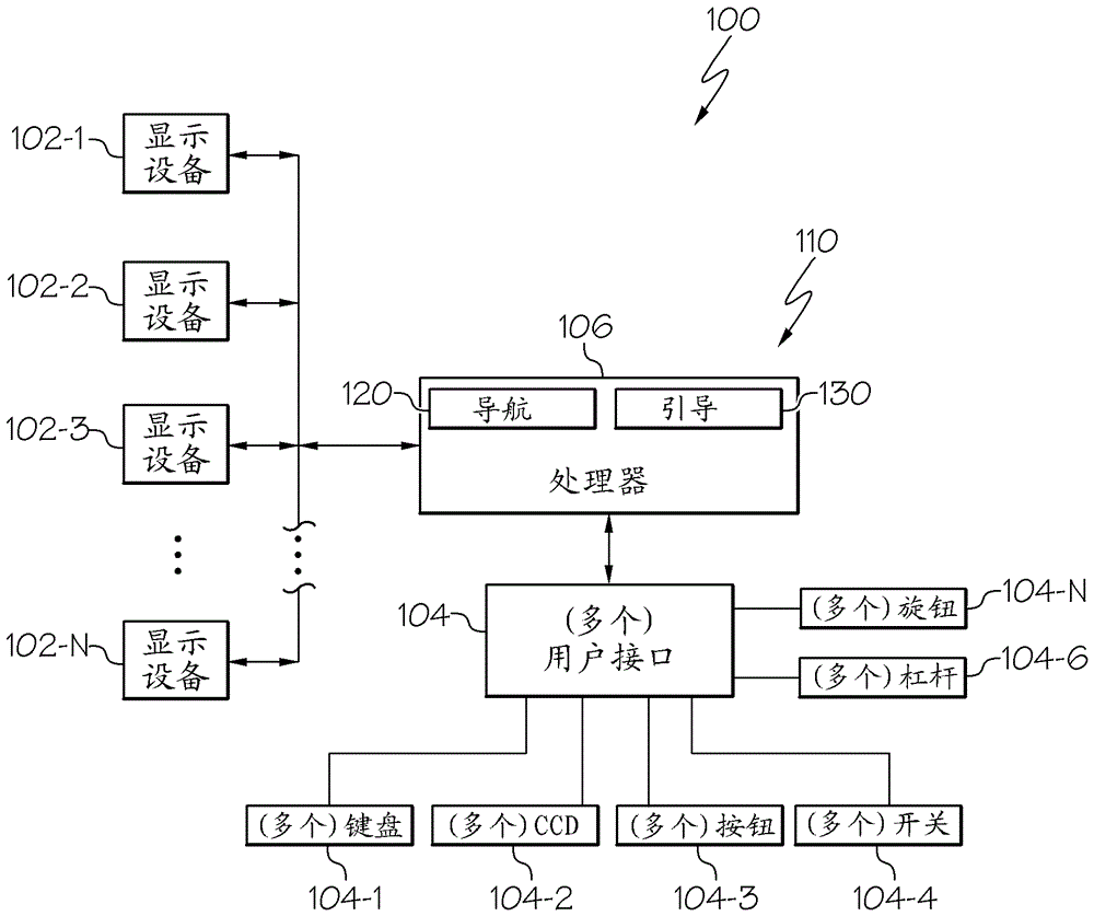
FIG. 1 is a functional block diagram of one embodiment of an aircraft system for providing automatic flight capability feedback to a pilot;
FIG. 2 depicts in flow chart form a process for providing automatic flight capability feedback that may be implemented in the system of FIG. 1; and
fig. 3 and 4 diagrammatically depict one instantiation of the process of fig. 2 that may be implemented by the system of fig. 1.
Detailed Description
The following detailed description is merely exemplary in nature and is not intended to limit the invention or the application and uses of the invention. As used herein, the word "exemplary" means "serving as an example, instance, or illustration. Thus, any embodiment described herein as "exemplary" is not necessarily to be construed as preferred or advantageous over other embodiments. All of the embodiments described herein are exemplary embodiments provided to enable persons skilled in the art to make or use the invention and not to limit the scope of the invention which is defined by the claims. Furthermore, there is no intention to be bound by any expressed or implied theory presented in the preceding technical field, background, brief summary or the following detailed description.
Referring initially to FIG. 1, a functional block diagram of one embodiment of an aircraft system 100 for providing automatic flight capability feedback to a pilot is depicted and includes a plurality of display devices 102 (102-1, 102-2 … … 102-N), one or more user interfaces 104 (104-1, 104-2 … … 104-N), and a processor 106. Each display device 102 is configured to reproduce various types of images in response to image reproduction display commands received from the processor 106. As will be described in more detail further below, the image may be reproduced at both the nominal resolution and the degraded resolution. As used herein, the term "degraded resolution" is a resolution that is less than the nominal resolution.
The display devices 102 may vary in number, configuration, and implementation. For example, the display device 102 may be configured as any of numerous types of aircraft avionics displays, including but not limited to: a multifunction display (MFD), a Primary Flight Display (PFD), a horizontal position indicator (HSI), or an Engine Indicating and Crew Alerting System (EICAS) displays a plurality of display devices. Moreover, the display device may be implemented using any of a number of types of display technologies, including, but not limited to, various Cathode Ray Tube (CRT) displays, various Liquid Crystal Displays (LCD), various Light Emitting Diode (LED) displays, various plasma displays, various heads-up displays (HUD), various projection displays, and various head-up displays (HUD), to name a few. Regardless of number, configuration, and implementation.
The user interface 104 is configured to receive user input from a user, such as, for example, a pilot. The user input may vary in type, but includes data such as flight plans and various flight constraint values associated therewith. One or more of the user interfaces 104 may also be used to supply various other types of signals in response to user input. For example, and as will be described further below, one of the user interfaces 104 may be used to supply a first signal indicating that the restriction selection function has been enabled, and the same or another user interface 104 may be configured to supply a second signal indicating that the automatic flight equipment function has been enabled.
Although the user interface 104 is illustrated using a single functional block for clarity and ease of depiction, it will be appreciated that the user interface 104 may be implemented using multiple user interfaces that may vary in configuration and implementation and may include any suitable hardware and software components that enable a pilot to interface with the system 100. As depicted, such components may include keyboards, cursor control devices, buttons, switches, levers, and knobs, to name a few. One or more of the user interfaces 104 may also include a display unit capable of displaying various types of computer-generated symbols and information, such as various CRT or flat panel display systems, such as LCD, OLED displays, projection displays, plasma displays, HDD, HUD, etc., and may be implemented as part of one or more of the display devices 102.
One or more of the user interfaces 104 may also be configured to supply tactile and/or audible feedback to a user (e.g., a pilot). For example, when implemented as a button, switch, lever, or knob, the user interface 104 may provide tactile feedback and/or audible (e.g., a "clicking" sound) feedback when manipulated.
The processor 106 is in operable communication with the display device 102 and the user interface 104. The processor 106 is coupled to receive various signals from one or more of the user interfaces 104 and is configured to, among other functions, provide automatic flight capability feedback in response to the received signals. The automatic flight capability feedback function will be described in more detail shortly. Before doing so, however, it should be appreciated that although the processor 106 is depicted in FIG. 1 using a single functional block, the illustrative embodiments are not so limited. Indeed, in some embodiments, the processor 106 may be implemented using multiple processors, components, or subcomponents of various systems located on or outside of the aircraft. Additionally, the systems and methods described herein are not limited to manned aircraft, and may also be implemented for other types of vehicles, such as, for example, space vehicles or unmanned vehicles.
Further, it should be appreciated that the processor 106 may be configured to implement any of a number of functions in an aircraft. However, in the depicted embodiment, the processor 106 is configured to implement a Flight Management System (FMS) 110. As is generally known, and as further depicted in fig. 1, the FMS 110 includes a navigation system 120 and a guidance system 130. The system 100 is specifically discussed as controlling the aircraft during a vertical descent or deceleration leg, although the exemplary embodiments discussed herein are equally applicable to other flight legs and scenarios.
The FMS 110, as is generally known, is configured to perform a wide variety of in-flight tasks during operation of the aircraft. These tasks include aircraft navigation and guidance, which are implemented by navigation system 120 and guidance system 130, respectively. Although not specifically shown, the FMS 110 may additionally include a database having any elements necessary for the operation of the aircraft and the creation and implementation of a flight plan (including waypoints, airports, terrain information, and applicable flight rules).
The navigation system 120 determines the current kinematic state of the aircraft. As such, in the exemplary embodiment, navigation system 120 includes any suitable position and orientation determining device, such as an Inertial Reference System (IRS), an airborne data orientation reference system (AHRS), a radio navigation assistance, or a Global Navigation Satellite System (GNSS). For example, the navigation system 120 provides at least the current position and velocity of the aircraft to the guidance system 130. Other navigation information may include current heading, current course, current trajectory, altitude, pitch angle, and any desired flight information.
The guidance system 130 uses various flight and engine models and algorithms to construct lateral and vertical profiles for the various legs that make up the flight plan based on navigation information received from the navigation system 120 (e.g., current position and velocity) and inputs from the pilot or other sources (e.g., desired destination). As an example, guidance system 130 may generate a flight plan based on considerations for timing, location, altitude, speed targets, and fuel economy. The guidance system 130 may also take into account aircraft specific parameters such as weight, fuel, and atmospheric conditions. In one scenario, aspects of a flight plan may be specified by Air Traffic Control (ATC), Federal Aviation Administration (FAA) rules, or European Aviation Safety Agency (EASA) rules.
The flight plan may include a number of legs between waypoints, each leg having an associated position, altitude, speed, and time at which the aircraft is scheduled to fly. As such, guidance system 130 generally constructs a flight plan leg from a first state (e.g., a current or future position, altitude, speed, and/or time) to a second state (e.g., a subsequent position, altitude, speed, and/or time). The guidance system 130 provides the flight plan in the form of guidance commands to a autopilot system, for example, not shown. For example, the commands generated by guidance system 130 associated with the flight plan may include pitch angle commands, pitch rate commands, roll angle commands, and velocity targets, which operate to achieve lateral and vertical profiles. In response to these pilot commands, the autopilot system generates appropriate actuator commands that function to control the flight characteristics of the aircraft via various actuators, not shown.
As noted above, the processor 106 is configured to implement a process for providing automatic flight capability feedback to the pilot in addition to the functions described above. The process, depicted in flow chart form in fig. 2, includes the processor 106 determining when a flight constraint value has been entered via one of the user interfaces 104 in response to various signals received from the user interfaces 104 (202). The processor 106 then determines which of the images rendered on one or more of the display devices 102 are associated with the entered flight constraint values (204). After determining which of the rendered images are associated with the entered flight constraint values, the processor 106 commands one or more of the display devices 102 to render at least a portion of the image associated with the flight constraint values at a degraded resolution (206). Before continuing, it is again noted that the term "degraded resolution" as used herein is a resolution that is less than the nominal resolution of the display device 102.
The processor 106 then determines whether both the constraint selection function and the automatic flight equipment function have been enabled (208, 210). If not, the processor 106 continues to command the display device 102 to render the image associated with the flight constraint value at the degraded resolution. However, if both the constraint selection function and the automatic flight equipment function have been enabled, the processor 106 commands the display device 102 to render the image associated with the flight constraint value at the nominal resolution (212).
To implement the processes described above, the processor 106, as may be appreciated, is coupled to at least selectively receive the constraint value signal, the first enable signal, and the second enable signal from one or more of the user interfaces 104. The constraint value signal represents a flight constraint value, the first enable signal indicates that the constraint selection function has been enabled, and the second enable signal indicates that the automatic flight equipment function has been enabled. It will be appreciated that the particular user interface 104 used to supply these signals may vary. Further, it will be appreciated that the image associated with the entered flight constraint value may vary.
To describe and depict the automatic flight capability feedback function of system 100 even more clearly, one particular instantiation of the process depicted in FIG. 2 will now be described. This particular instantiation is associated with the setting of the descent target such that the navigation system 120 is able to reach the descent target when armed and the navigation system 120 is armed to descend to the target. For this particular instantiation, the flight constraint value entered by the aircraft pilot is the descent target (e.g., 14,000 feet) at the particular waypoint.
As depicted in fig. 3, the processor 106 has determined that the image associated with the entered flight constraint value includes at least a portion 302 of a flight plan dialog box in which the descent target is entered, an altitude display 304 adjacent an altitude selection user interface (ASEL) 305, and a vertical position display (VSD) 306 depicting a vertical flight plan of the aircraft. As also depicted in fig. 3, all or part of these images 302, 304, 306 are rendered at a degraded resolution. For ease of illustration, dashed lines are used in the drawing to convey degraded resolution. These images are rendered with sufficient resolution to provide clear readability, but degraded resolution provides feedback to the pilot that something is more needed to do in order to reach the descent goal.
As is generally known, after a descent target is entered, the ASEL 305 turns to an altitude constraint (e.g., 14,000 feet) and is then pressed to supply a first enable signal. Preferably, any haptic and/or auditory feedback associated with manipulation of the ASEL 305 is also degraded. That is, any tactile and/or audible clicks/twitches are finely degraded relative to the nominal tactile and/or audible feedback, again alerting the pilot to the need to do more. Until the navigation system 120 is armed, for example, by pressing a VNAV on the appropriate user interface 104, the processor 106 further commands the VSD 306 to reproduce the desired, maximum, and minimum descent route angles and rates that may satisfy the constraints along with the current flight route (showing the flight route stroking the desired route), at a degraded resolution, so the pilot remains aware of the window of possibilities. As also depicted in fig. 3, in some embodiments, various other graphical elements, such as a Vertical Trajectory Alert (VTA) 308, and their associated sounds, will be rendered at a reduced resolution until the navigation system 120 is armed.
When the pilot does press the VNAV on the appropriate user interface 104 to arm the navigation system 120, the press is accompanied by nominal (as opposed to degraded) tactile and/or audible feedback, and as depicted in fig. 4, the flight plan dialog box 302, the altitude display 304, the flight plan and VTA 308 on the VSD 306 (and all associated tactile and/or audible feedback) are all rendered at the nominal resolution.
The systems and methods described herein provide aircraft autopilot capability feedback to aircraft pilots to thereby prevent or at least inhibit potential override errors that may cause operational errors. The system and method uses graphics that are finely and contextually conveyed in a manner that naturally conforms to how the visual cortex handles graphical information and how the mind makes a quick and subconscious decision about the information. The system may also use audible and tactile feedback.
Degradation described herein spans multiple modalities-thus an audible alert has a normal state and a degraded state, a visual component has a nominal state and a degraded state, and these are asserted on the underlying logic being satisfied, which can be several if-then-else statements (e.g., 1 constraint applied, 2-ASEL set, 3-VNAV equipment). The degraded state also spans all associated displays until the logic is satisfied, so the flight crew will see the degraded state across the cockpit and have a greater chance of catching the error (e.g., 1-see it in the constraint GUI, 2-see it with ASEL).
Those of skill in the art would appreciate that the various illustrative logical blocks, modules, circuits, and algorithm steps described in connection with the embodiments disclosed herein may be implemented as electronic hardware, computer software, or combinations of both. Some of the embodiments and implementations are described above in terms of functional and/or logical block components (or modules) and various processing steps. However, it should be appreciated that such block components (or modules) may be realized by any number of hardware, software, and/or firmware components configured to perform the specified functions. To clearly illustrate this interchangeability of hardware and software, various illustrative components, blocks, modules, circuits, and steps have been described above generally in terms of their functionality. Whether such functionality is implemented as hardware or software depends upon the particular application and design constraints imposed on the overall system. Skilled artisans may implement the described functionality in varying ways for each particular application, but such implementation decisions should not be interpreted as causing a departure from the scope of the present invention. For example, an embodiment of a system or component may employ various integrated circuit components, e.g., memory elements, digital signal processing elements, logic elements, look-up tables, or the like, which may carry out a variety of functions under the control of one or more microprocessors or other control devices. Furthermore, those skilled in the art will appreciate that the embodiments described herein are merely exemplary implementations.
The various illustrative logical blocks, modules, and circuits described in connection with the embodiments disclosed herein may be implemented or performed with the following: a general purpose processor, a Digital Signal Processor (DSP), an Application Specific Integrated Circuit (ASIC), a Field Programmable Gate Array (FPGA) or other programmable logic device, discrete gate or transistor logic, discrete hardware components, or any combination thereof designed to perform the functions described herein. A general purpose processor may be a microprocessor, but in the alternative, the processor may be any conventional processor, controller, microcontroller, or state machine. A processor may also be implemented as a combination of computing devices, e.g., a combination of a DSP and a microprocessor, a plurality of microprocessors, one or more microprocessors in conjunction with a DSP core, or any other such configuration.
The steps of a method or algorithm described in connection with the embodiments disclosed herein may be embodied directly in hardware, in a software module executed by a processor, or in a combination of the two. A software module may reside in RAM memory, flash memory, ROM memory, EPROM memory, EEPROM memory, registers, hard disk, a removable disk, a CD-ROM, or any other form of storage medium known in the art. An exemplary storage medium is coupled to the processor such the processor can read information from, and write information to, the storage medium. In the alternative, the storage medium may be integral to the processor. The processor and the storage medium may reside in an ASIC. The ASIC may reside in a user terminal. In the alternative, the processor and the storage medium may reside as discrete components in a user terminal.
In this document, relational terms such as first and second, and the like may be used solely to distinguish one entity or action from another entity or action without necessarily requiring or implying any actual such relationship or order between such entities or actions. Numerical orders such as "first," "second," "third," and the like, simply denote different singles of a plurality and do not imply any order or sequence unless specifically defined by the claim language. The order of text in any claims does not imply that the process steps must be performed in a temporal or logical order according to such order, unless specifically defined by the language of the claims. The process steps may be interchanged in any order without departing from the scope of the invention as long as such an interchange does not contradict the claim language and is not logically meaningful.
In addition, depending on the context, words such as "connected" or "coupled" used in describing relationships between different elements do not imply that a direct physical connection must be made between the elements. For example, two elements may be connected to each other physically, electronically, logically, or in any other manner, through one or more additional elements.
While at least one exemplary embodiment has been presented in the foregoing detailed description of the invention, it should be appreciated that a vast number of variations exist. It should also be appreciated that the exemplary embodiment or exemplary embodiments are only examples, and are not intended to limit the scope, applicability, or configuration of the invention in any way. Rather, the foregoing detailed description will provide those skilled in the art with a convenient road map for implementing an exemplary embodiment of the invention. It being understood that various changes may be made in the function and arrangement of elements described in an exemplary embodiment without departing from the scope of the invention as set forth in the appended claims.
Claims (11)
Applications Claiming Priority (2)
| Application Number | Priority Date | Filing Date | Title |
|---|---|---|---|
| US15/095310 | 2016-04-11 | ||
| US15/095,310 US10318003B2 (en) | 2016-04-11 | 2016-04-11 | System and method for providing aircraft autoflight capability feedback to a pilot |
Publications (2)
| Publication Number | Publication Date |
|---|---|
| CN107284679A CN107284679A (en) | 2017-10-24 |
| CN107284679B true CN107284679B (en) | 2022-08-12 |
Family
ID=58387649
Family Applications (1)
| Application Number | Title | Priority Date | Filing Date |
|---|---|---|---|
| CN201710228947.1A Active CN107284679B (en) | 2016-04-11 | 2017-04-10 | System and method for providing pilot feedback on aircraft autoflight capability |
Country Status (3)
| Country | Link |
|---|---|
| US (1) | US10318003B2 (en) |
| EP (1) | EP3232162B1 (en) |
| CN (1) | CN107284679B (en) |
Families Citing this family (29)
| Publication number | Priority date | Publication date | Assignee | Title |
|---|---|---|---|---|
| US10321587B2 (en) * | 2017-02-03 | 2019-06-11 | Google Llc | Integrated connector receptacle device |
| US11790789B2 (en) | 2020-06-05 | 2023-10-17 | Honeywell International Inc. | Gliding vertical margin guidance methods and systems |
| US12202616B2 (en) | 2021-11-04 | 2025-01-21 | General Electric Company | Relight of a propulsion system with a fuel cell |
| US11794912B2 (en) | 2022-01-04 | 2023-10-24 | General Electric Company | Systems and methods for reducing emissions with a fuel cell |
| US11719441B2 (en) | 2022-01-04 | 2023-08-08 | General Electric Company | Systems and methods for providing output products to a combustion chamber of a gas turbine engine |
| US12123361B2 (en) | 2022-01-04 | 2024-10-22 | General Electric Company | Systems and methods for providing output products to a combustion chamber of a gas turbine engine |
| US12037952B2 (en) | 2022-01-04 | 2024-07-16 | General Electric Company | Systems and methods for providing output products to a combustion chamber of a gas turbine engine |
| US11933216B2 (en) | 2022-01-04 | 2024-03-19 | General Electric Company | Systems and methods for providing output products to a combustion chamber of a gas turbine engine |
| US11970282B2 (en) | 2022-01-05 | 2024-04-30 | General Electric Company | Aircraft thrust management with a fuel cell |
| US12034298B2 (en) | 2022-01-10 | 2024-07-09 | General Electric Company | Power source for an aircraft |
| US12074350B2 (en) | 2022-01-21 | 2024-08-27 | General Electric Company | Solid oxide fuel cell assembly |
| US12037124B2 (en) | 2022-01-21 | 2024-07-16 | General Electric Company | Systems and method of operating a fuel cell assembly |
| US12351329B2 (en) | 2022-01-21 | 2025-07-08 | General Electric Company | Systems and method of operating a fuel cell assembly |
| US11804607B2 (en) | 2022-01-21 | 2023-10-31 | General Electric Company | Cooling of a fuel cell assembly |
| US11967743B2 (en) | 2022-02-21 | 2024-04-23 | General Electric Company | Modular fuel cell assembly |
| US12170390B2 (en) | 2022-02-21 | 2024-12-17 | General Electric Company | Systems and method of operating a fuel cell assembly, a gas turbine engine, or both |
| US12129789B2 (en) | 2022-02-21 | 2024-10-29 | General Electric Company | Systems and method of operating a fuel cell assembly, a gas turbine engine, or both |
| US12025061B2 (en) | 2022-04-04 | 2024-07-02 | General Electric Company | Gas turbine engine with fuel cell assembly |
| US12412914B2 (en) | 2022-05-16 | 2025-09-09 | General Electric Company | Environmental control system having a fuel cell assembly |
| US12428164B2 (en) | 2022-05-16 | 2025-09-30 | General Electric Company | Environmental control system having a fuel cell assembly |
| US12043406B2 (en) | 2022-05-27 | 2024-07-23 | General Electric Company | Method of operating a fuel cell assembly for an aircraft |
| US11817700B1 (en) | 2022-07-20 | 2023-11-14 | General Electric Company | Decentralized electrical power allocation system |
| US12301002B2 (en) | 2022-08-26 | 2025-05-13 | General Electric Company | Power dispatch control system for multiple power generation sources |
| US11923586B1 (en) | 2022-11-10 | 2024-03-05 | General Electric Company | Gas turbine combustion section having an integrated fuel cell assembly |
| US12078350B2 (en) | 2022-11-10 | 2024-09-03 | General Electric Company | Gas turbine combustion section having an integrated fuel cell assembly |
| US12240613B2 (en) | 2022-11-10 | 2025-03-04 | General Electric Company | Gas turbine combustion section having an integrated fuel cell assembly |
| US11859820B1 (en) | 2022-11-10 | 2024-01-02 | General Electric Company | Gas turbine combustion section having an integrated fuel cell assembly |
| CN118532265A (en) | 2023-02-23 | 2024-08-23 | 通用电气公司 | Gas turbine engine and fuel cell assembly |
| CN118532263A (en) | 2023-02-23 | 2024-08-23 | 通用电气公司 | Gas turbine engine and fuel cell assembly |
Citations (4)
| Publication number | Priority date | Publication date | Assignee | Title |
|---|---|---|---|---|
| GB9118513D0 (en) * | 1991-08-29 | 1991-10-16 | British Aerospace | An eye-slaved panoramic display apparatus |
| CN105222805A (en) * | 2009-07-26 | 2016-01-06 | 阿斯潘航空电子有限公司 | Avionics devices, systems and methods |
| CN105278362A (en) * | 2015-01-16 | 2016-01-27 | 深圳一电科技有限公司 | Unmanned reconnaissance system control method, device and system |
| CN105389407A (en) * | 2014-08-21 | 2016-03-09 | 波音公司 | integrated visualization and analysis of a complex system |
Family Cites Families (10)
| Publication number | Priority date | Publication date | Assignee | Title |
|---|---|---|---|---|
| FR2935180B1 (en) | 2008-08-20 | 2010-12-03 | Airbus France | INTERACTIVE DEVICE FOR CONTROLLING SERVITUDES IN AN AIRCRAFT |
| US8369693B2 (en) * | 2009-03-27 | 2013-02-05 | Dell Products L.P. | Visual information storage methods and systems |
| US20110246002A1 (en) | 2010-04-02 | 2011-10-06 | Cloudahoy Inc. | Systems and methods for aircraft flight tracking and analysis |
| US9424753B2 (en) | 2011-07-08 | 2016-08-23 | General Electric Company | Simplified user interface for an aircraft |
| US9054516B2 (en) * | 2011-07-20 | 2015-06-09 | Siemens Industry, Inc. | Circuit breaker trip notification systems and methods |
| US20130211635A1 (en) * | 2011-11-29 | 2013-08-15 | Airbus Operations (Sas) | Interactive dialog devices and methods for an operator of an aircraft and a guidance system of the aircraft |
| US9723300B2 (en) * | 2014-03-17 | 2017-08-01 | Spatial Intelligence Llc | Stereoscopic display |
| BR112017002615A2 (en) * | 2014-09-03 | 2017-12-05 | Quaero Ltd | a human machine interface device for aircraft |
| US10540007B2 (en) * | 2016-03-04 | 2020-01-21 | Rockwell Collins, Inc. | Systems and methods for delivering imagery to head-worn display systems |
| US10091466B2 (en) * | 2016-03-18 | 2018-10-02 | Motorola Solutions, Inc. | Visual perception determination system and method |
-
2016
- 2016-04-11 US US15/095,310 patent/US10318003B2/en active Active
-
2017
- 2017-03-15 EP EP17161151.0A patent/EP3232162B1/en active Active
- 2017-04-10 CN CN201710228947.1A patent/CN107284679B/en active Active
Patent Citations (4)
| Publication number | Priority date | Publication date | Assignee | Title |
|---|---|---|---|---|
| GB9118513D0 (en) * | 1991-08-29 | 1991-10-16 | British Aerospace | An eye-slaved panoramic display apparatus |
| CN105222805A (en) * | 2009-07-26 | 2016-01-06 | 阿斯潘航空电子有限公司 | Avionics devices, systems and methods |
| CN105389407A (en) * | 2014-08-21 | 2016-03-09 | 波音公司 | integrated visualization and analysis of a complex system |
| CN105278362A (en) * | 2015-01-16 | 2016-01-27 | 深圳一电科技有限公司 | Unmanned reconnaissance system control method, device and system |
Also Published As
| Publication number | Publication date |
|---|---|
| EP3232162A1 (en) | 2017-10-18 |
| US20170293358A1 (en) | 2017-10-12 |
| EP3232162B1 (en) | 2020-06-17 |
| US10318003B2 (en) | 2019-06-11 |
| CN107284679A (en) | 2017-10-24 |
Similar Documents
| Publication | Publication Date | Title |
|---|---|---|
| CN107284679B (en) | System and method for providing pilot feedback on aircraft autoflight capability | |
| US9501936B2 (en) | Aircraft systems and methods for displaying spacing information | |
| US9126694B2 (en) | Display systems and methods for providing displays having an integrated autopilot functionality | |
| US10540902B2 (en) | Flight planning and communication | |
| US8121747B2 (en) | Flight management system, process, and program product enabling dynamic switching between non-precision approach modes | |
| US9499279B2 (en) | System and method for displaying runway approach information | |
| US9043043B1 (en) | Autonomous flight controls for providing safe mode navigation | |
| CN107014383A (en) | The display of meteorological data in aircraft | |
| US10971155B2 (en) | Aircraft systems and methods for monitoring onboard communications | |
| US20160264254A1 (en) | Methods and systems for integrating auto pilot functions on a display | |
| AU2016355179B2 (en) | System and method for aircraft operations including path guidance panel with conditional waypoints | |
| US20160123763A1 (en) | Methods and systems for displaying flight information | |
| CN104575107B (en) | For metering needle to the system and method for the alarm of expected runway | |
| CN113284368B (en) | Apparatus, method and aircraft for displaying future waypoints and constraints | |
| US20170349295A1 (en) | System and method for providing aircraft lateral navigation capability feedback to a pilot | |
| US9254911B2 (en) | Fault tolerant lateral waypoint sequencing system and method | |
| EP3578925A1 (en) | Automatic from-waypoint updating system and method | |
| EP4358067A1 (en) | Methods and systems for aircraft procedure verification using a virtual cursor | |
| US11769417B2 (en) | Methods and systems for representing flight mode annunciation information on a cockpit display | |
| EP3951323A1 (en) | Methods and systems for representing flight mode annunciation information on a cockpit display |
Legal Events
| Date | Code | Title | Description |
|---|---|---|---|
| PB01 | Publication | ||
| PB01 | Publication | ||
| SE01 | Entry into force of request for substantive examination | ||
| SE01 | Entry into force of request for substantive examination | ||
| GR01 | Patent grant | ||
| GR01 | Patent grant |