Disclosure of Invention
The invention mainly aims to provide a battery pack device, aiming at solving the technical problems that the existing battery pack device is unreliable in heat dissipation and insulation design scheme and is easy to cause safety accidents.
The present invention proposes a battery pack device comprising: a plurality of substantially parallel units, a heat sink, a bus bar, and an insulating member;
the bus connecting bar is positioned between the radiator and the plurality of basic parallel units and is connected with the radiator through a radiator screw; the bus connecting bar is positioned at the top end of the end surface where the lugs of the basic parallel units are positioned, and the lugs of the basic parallel units are connected to form parallel connection;
a plurality of the basic parallel units are connected in series to form a series body; each of said basic parallel units including a voltage acquisition terminal, said voltage acquisition terminal being secured to said basic parallel unit through said buss connection bar;
the insulating member includes a first insulating member, a second insulating member, and a third insulating member; the first insulating member is fixed between the bus bar and the heat sink by the heat sink screw; the second insulating member is located around the radiator screw; the third insulating member is located at the boundary of the voltage collecting terminal corresponding to the heat sink.
Preferably, the basic parallel unit comprises a plurality of single battery cells, a plurality of insulating supports and one or more tab fixing strips;
the basic parallel unit is formed by arranging a plurality of insulating supports and a plurality of single battery cells at intervals in sequence, and the insulating supports are arranged at two ends of the basic parallel unit;
the lugs of the two adjacent monomer cells are bent and then clamped in parallel on the insulating support between the two adjacent monomer cells and are fixed through the lug fixing strips.
Preferably, the single battery cell is a soft-package battery cell; the positive electrode lugs and the negative electrode lugs of the single battery cells are respectively distributed at two opposite ends or two same ends of the single battery cells; a plurality of through holes are respectively distributed on the positive electrode lug and the negative electrode lug; fixing holes corresponding to the positive and negative pole lug through holes are distributed on the lug fixing strip; the radiator screw and the voltage acquisition terminal respectively pass through the through hole and the fixing hole at corresponding positions.
Preferably, the radiator comprises an air-cooled radiator or a liquid-cooled radiator;
the air-cooled radiator includes: a tooth-shaped heat-conducting plate, wherein the opening direction between teeth of the tooth-shaped heat-conducting plate is far away from the serial body;
the liquid cooling radiator comprises: the liquid cooling pipeline assembly is arranged in a preset groove body on the heat conduction plate, and the heat conduction plate is sealed with the liquid cooling pipeline through a heat conduction material.
Preferably, the first insulating member includes: one of a ceramic substrate or a thermally conductive adhesive cover.
Preferably, the first insulating member further includes: and the heat conduction insulating film is closely attached to one surface, close to the bus connecting bar, of the first insulating part.
Preferably, the second insulating member includes: an insulating sleeve and an insulating washer;
the insulating sleeve sleeves the part of the radiator screw in the radiator; the insulating washer is positioned on a contact surface of the radiator screw which is close to the radiator end when the radiator screw passes through the first insulating part.
Preferably, the third insulating member includes: one of an insulating film or a thermally conductive gum cover;
preferably, the insulating member further includes: a fourth insulating member;
the fourth insulating member is located between two adjacent basic parallel units, and separates the bus connecting bars which are not required to be connected when the two adjacent basic parallel units form a series connection relationship;
the fourth insulating component is an insulating material isolation sleeve.
Preferably, the bus connecting bar is connected with the lugs of the plurality of basically parallel units through pit laser welding; the basic parallel unit is connected with the bus connecting bar in parallel by laser welding the lugs; and the adjacent basically parallel units are connected in series with the bus connecting bar through laser welding of the lugs.
The invention has the beneficial technical effects that: in the multi-lug power battery cell, the lugs are directly conducted with the current collector, and the heat transfer by the lugs is very effective for controlling the internal temperature environment of the battery cell. But since the tabs are also the current paths, the electrical isolation between the heat sink and the substantially parallel cells is critical. The delicate and tight electrical insulation design between the basic parallel unit and the radiator ensures the electrical safety of the whole battery pack device. Meanwhile, the basic parallel unit tabs and the bus connecting bars are connected in a double mode such as welding and threaded connection, and the structural stability of the whole battery pack device is guaranteed. According to the invention, a special welding process is adopted between the bus connecting bar and the lugs of the basic parallel units, so that the welding performance and the smoothness of the surface of the welded bus connecting bar are ensured, and the electric insulation performance between the radiator and the basic parallel units is ensured on the premise of ensuring effective heat conduction and electric conduction connection. The lithium ion battery pack device reliably solves the problem of electric insulation between the radiator and the basic parallel unit while utilizing the tabs to transfer heat, and improves the use safety.
Detailed Description
It should be understood that the specific embodiments described herein are merely illustrative of the invention and are not intended to limit the invention.
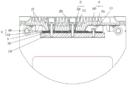
Referring to fig. 1, 3 and 4, an embodiment of the present invention provides a battery pack apparatus including: a plurality of basic parallel units 1, a heat sink 2, a bus bar 3, and an insulating member;
the bus connecting bar 3 is positioned between the radiator 2 and the plurality of basic parallel units 1 and is connected through radiator screws 20; the bus connecting bar 3 is positioned at the top end of the end surface where the lugs 10 of the basic parallel unit 1 are positioned, and the lugs 10 of the basic parallel unit 1 are connected to form parallel connection;
a plurality of the basic parallel units 1 are connected in series to form a series body; each of the basic parallel units 1 includes a voltage collecting terminal 11, and the voltage collecting terminal 11 is fixed on the basic parallel unit 1 through the bus connecting bar 3;
the insulating member includes a first insulating member 4, a second insulating member 5, and a third insulating member 6; the first insulating member 4 is fixed between the bus bar 3 and the radiator 2 by the radiator screw 20; the second insulating member 5 is positioned around the radiator screw 20; the third insulating member 6 is located at a boundary between the region where the voltage collecting terminal 11 is located and the heat sink 2.
In the embodiment of the invention, the multi-lug power battery cell is a lithium ion battery cell with a soft package structure, the lugs are directly conducted with each layer of current collector, and the heat transfer of the lugs is utilized to ensure that the internal temperature environment of the battery cell is more effective. The embodiment of the invention realizes the parallel connection inside the basic parallel units 1 through the bus connecting bar 3, and simultaneously realizes the series connection between the adjacent basic parallel units 1; the bus bar 3 is located at the top end of the end surface of the basic parallel unit 1 where the tab 10 is located, the top end being the upper portion when the end surface where the tab 10 is located faces upward. However, the tab is also a channel for conducting current inside and outside the battery cell, so that the electrical insulation between the heat sink and the tab of the battery cell is very critical. The lithium ion battery pack device of the embodiment of the invention reliably solves the electrical insulation problem between the radiator and the basic parallel units by arranging the delicate insulation component while utilizing the tabs to transfer heat, and ensures the use safety of the whole battery pack device by the precise and strict electrical insulation design between the serial body formed by the plurality of basic parallel units and the radiator.
Referring to fig. 2, the basic parallel unit includes a plurality of unit cells 12, a plurality of insulating supports 13, and one or more tab fixing strips 14;
the basic parallel unit 1 is formed by sequentially arranging a plurality of insulating supports 13 and a plurality of single battery cells 12 at intervals, and the insulating supports 13 are arranged at two ends;
the tabs 10 of two adjacent single battery cells 12 are bent and then clamped in parallel on the insulating support 13 between the two single battery cells and fixed by the tab fixing strips 14.
The battery assembly in the embodiment of the present invention is an assembly of the soft package core 4P12S, but is not limited to the above combination. The basic parallel unit 1 in the embodiment of the invention is composed of four soft-package single battery cells 12, five insulating supports 13 and two tab fixing strips 14, wherein the insulating supports are two thick and thin plastic supports in the embodiment of the invention. The positive pole lug 10 of negative pole of monomer electricity core 12 is respectively at its both ends, through punching a hole and bend back positive pole lug and positive pole lug, negative pole lug and negative pole lug two liang of relative, the homopolar utmost point lug 10 card of two adjacent monomer electricity cores 12 is on being located its middle thick plastic support, two liang of electric cores are kept apart through thick plastic support insulation, the both sides terminal surface of parallelly connected unit 1 is thin plastic support basically to under the prerequisite of guaranteeing internal insulation and keeping apart, save group battery device space volume. The tab fixing strips 14 are also clamped on the thick plastic support and under the paired bent tabs 10, and are used for fixing the tabs 10 and the parts on the tabs, such as the radiator 2 and the like. The internal insulation of the battery pack device is ensured while providing better mechanical strength. When the basic parallel unit 1 is a dual-cell parallel body, the basic parallel unit 1 only needs one tab fixing strip 14 to fix the single cell 12 on the insulating support 13.
Further, the single battery cell 12 is a soft-package lithium ion battery cell; the positive and negative electrode tabs of the single battery cells 12 are respectively distributed at two opposite ends or two same ends of the single battery cells 12; a plurality of through holes 100 are respectively distributed on the positive and negative electrode tabs 10; fixing holes 140 corresponding to the through holes 100 of the positive and negative electrode tabs 10 are distributed on the tab fixing strip 14; the heat sink screw 20 and the voltage collecting terminal 11 are inserted into the through hole 100 and the fixing hole 140 at corresponding positions, respectively.
In the embodiment of the invention, the single battery cell 12 is a soft-packaged battery cell in which the positive electrode tab 10 and the negative electrode tab 10 are respectively distributed at two opposite ends of the single battery cell 12, the tabs 10 of the soft-packaged battery cell are in contact with each layer of current collector, which is favorable for heat conduction and heat dissipation, and realizes effective control of the heat inside the battery cell, and the positive electrode tab 10 and the negative electrode tab 10 of the soft-packaged battery cell are designed at two opposite ends of the soft-packaged single battery cell 12, which is more favorable for heat exchange between the heat inside the single battery cell 12 and the radiator 2 through the tabs 10, so that heat conduction and heat. The heat sink 2 passes through the heat sink screw through holes 202 of the heat sink 2, so that the heat sink screws 20 are fastened to the tab fixing bars 14 through the corresponding through holes 100 and the fixing holes 140, thereby facilitating heat exchange between the battery pack device and the heat sink 2 and ensuring structural stability of the entire battery pack device. Meanwhile, the battery pack in the embodiment of the invention is designed to further improve the structural stability of the battery pack device, and meanwhile, the whole battery pack device is fixed together by arranging the pull rod screws at four corners of the battery pack device.
Further, the radiator 2 includes an air-cooled radiator 21 or a liquid-cooled radiator 22;
the air-cooled radiator 21 includes: a tooth-shaped heat-conducting plate, wherein the opening direction between teeth of the tooth-shaped heat-conducting plate is far away from the serial body;
the liquid cooling radiator 22 includes: the liquid cooling device comprises a heat conduction plate 220 and a plurality of liquid cooling pipelines 221, wherein the plurality of liquid cooling pipelines 221 are assembled on the heat conduction plate 220 and are preset in a groove body, and the heat conduction plate 220 and the liquid cooling pipelines 221 are sealed through a heat conduction material 222.
In the embodiment of the present invention, the radiator 2 is an air-cooled radiator 21 composed of a toothed heat conducting plate, the structure is simple, heat exchange is conveniently realized, the material of the toothed heat conducting plate is a metal material with high heat conductivity coefficient, such as copper, aluminum, etc., and the embodiment of the present invention preferably uses metal aluminum.
Referring to fig. 7, the radiator 2 in another embodiment of the present invention is changed from an air-cooled radiator 21 to a liquid-cooled radiator 22, and the rest is not changed. The liquid cooling pipes 221 are assembled in the grooves of the heat conducting plate 220, sealed with a material having a good heat conducting property such as heat conducting cement 222, and then fastened by a structural member. When higher temperature liquid is introduced into the liquid cooling radiator 22, the battery cell can be heated, and the liquid cooling radiator is used as a heating component for using the battery pack device in a low temperature environment.
Further, the first insulating member 4 includes: one of a ceramic substrate 40 or a thermally conductive gel jacket 42.
Further, the first insulating member 4 further includes: and a heat conductive insulating film 41, wherein the heat conductive insulating film 41 is in close contact with one surface of the first insulating member 4 close to the bus bar 3.
Referring to fig. 3 and 4, in the embodiment of the present invention, a double insulation measure is provided between the heat sink 2 and the charged bus bar 3, and the ceramic substrate 40 and the heat conductive insulating film 41 with good heat conductivity are used, so that the heat sink 2 is in insulated contact with the bus bar 3, and the heat conductive insulating film 41 can enhance the heat transfer effect between the heat sink 2 and the battery pack device.
Referring to fig. 5 and 6, a double insulation measure between the heat sink 2 and the bus bar 3 in another embodiment of the present invention uses a thermally conductive adhesive cover 42 and a thermally conductive insulating film 41. The heat-conducting rubber sleeve 42 is made of high polymer materials such as rubber, plastic and the like with good insulating property and moderate heat-conducting property. The heat conducting rubber sleeve 42 covers the part of the radiator 2 facing the bus connecting bar 3, and although the heat conducting and radiating performance of the heat conducting rubber sleeve 42 is not as good as that of the ceramic substrate 40, the assembly is convenient, and the insulation protection is simpler.
Further, the second insulating member 5 includes: an insulating sleeve 50 and an insulating washer 51; the insulating sleeve 50 covers the part of the radiator screw 20 in the radiator 2; the insulating washer 51 is positioned on a contact surface of the radiator screw 20 which is close to the end of the radiator 2 when passing through the first insulating member 4.
In the embodiment of the invention, the radiator 2 is fastened on the lug fixing strip 14 by the radiator screw 20, and the electric insulation protection is carried out between the radiator screw 20 and the radiator 2 by the insulating sleeve 50 and the insulating washer 51, so that the battery pack device is ensured to have better mechanical strength, and the insulation protection is improved.
Further, the third insulating member 6 includes: one of the insulating film 60 or the thermally conductive adhesive cover 42;
in the embodiment of the present invention, the boundary of the voltage collecting terminal 11 corresponding to the heat sink 2 is insulated and protected by an insulating film 60. On the lower surface of the above-mentioned voltage collecting terminal 11 corresponding to the heat sink 2, an insulating film 60 is fixed with a plastic screw 61 to secure a sufficient insulation distance. The voltage collecting terminal 11 is located at the end of each basic parallel unit 1, the battery pack in the embodiment of the present invention is 4P12S, and there are twelve basic parallel units 1, so the total voltage collecting terminal is added in the embodiment of the present invention, and the third insulating member 6 has thirteen positions, so the insulating protection layout of the third insulating member 6 also has important significance.
In another embodiment of the present invention, the third insulating member 6 employs the heat conductive rubber sleeve 42, so that the first insulating member 4 and the third insulating member 6 can be designed in a continuous layout, the structure is simpler and more convenient, and the operation is convenient.
Further, the insulating member further includes: a fourth insulating member 7;
the fourth insulating member 7 is located between two adjacent basic parallel units 1, and separates the bus connecting bar 3 which is not required to be connected when the two adjacent basic parallel units 1 form a series connection relationship; the fourth insulating component is an insulating material isolation sleeve.
In the embodiment of the invention, the tabs 10 of the positive electrode and the negative electrode of the soft-package single battery cell 12 are respectively positioned at two opposite sides, so that the tabs 10 of the basic parallel units 1 after being connected in parallel are also positioned at two opposite end surfaces, the bus connection bars 3 are respectively positioned at the external opposite sides of the two opposite end surfaces to ensure the parallel connection in the basic parallel units 1, and then the bus connection bars 3 are separated by distributing fourth insulating parts 7 at intervals from top to bottom, so that the bus connection bars 3 of the positive electrode and the negative electrode of twelve basic parallel units 1 are sequentially connected to form series connection. In another embodiment of the present invention, the tabs 10 of the positive electrode and the negative electrode of the soft-package single battery cell 12 are respectively located at two sides of the boundary at the same end, the bus bar 3 is disposed on the top of the end surface where the tab end of the basic parallel unit 1 is located, the battery pack device is defined to be placed in a direction that the end surface where the tab end is located faces upwards, the internal parts of the basic parallel units 1 are connected in parallel, and adjacent basic parallel units 1 are connected in series. In the embodiment of the invention, the insulating material isolation sleeve is a rubber isolation sleeve which isolates the ceramic substrate 40, the heat-conducting insulating film 41 and the bus connecting bar 3 which is not required to be connected in series. The two ends of the part of the rubber isolation sleeve extending into the radiator 2 are distributed with insulating films to strengthen the insulation.
In another embodiment of the present invention, the rubber isolation sleeve isolates the bus bar 3 which is not required to be connected in the series connection, the heat conductive rubber sleeve 42 extends from the first insulating member 4, and is bent into an L shape along the contact surface with the rubber isolation sleeve to extend and arrange in the direction of the heat sink, the heat conductive insulating film 41 is tightly attached to the opposite surface of the heat conductive rubber sleeve 42 away from the heat sink, and is folded into a zigzag shape at the corner in contact with the rubber isolation sleeve, so that the heat conductive insulating film 41 is tightly attached and contacted between the heat conductive rubber sleeve 42 and the rubber isolation sleeve, and the insulation protection effect is better.
Referring to fig. 8, the busbar 3 is connected to a plurality of tabs 10 of the basic parallel unit 1 by laser welding through a sink 8; the basic parallel unit 1 is connected with the bus connecting bar 3 in parallel through laser welding lugs 10; the adjacent substantially parallel units 1 are connected in series with the busbar 3 by laser welding tabs 10.
In the embodiment of the invention, two oppositely bent homopolar lugs 10 of two adjacent cells and a bus connecting bar 3 are divided into three layers, laser welding is carried out twice, the two oppositely bent homopolar lugs 10 of the two adjacent cells are firstly connected in parallel in pairs by laser welding, and then the bus connecting bar 3 and the lugs 10 are connected by laser welding through the sunk pits 8 to form a parallel connection body of four cells. Since the upper surface of the bus bar 3 needs to be covered with a thin heat conductive insulating film 41, in order to prevent the film from being punctured, the top of the bus bar 3 is designed with a sunken hole 8 and a protection round corner 81 during welding. The material thickness at the bottom of the pit 8 is close to the thickness of the pole lug so as to facilitate laser welding. The depth of the sunken hole 8 ensures that the laser welding spot and welding spatter are not higher than the top surface of the bus bar 3, so as to prevent the heat-conducting insulating film 41 from being punctured due to uneven upper surface of the bus bar 3. The two oppositely bent tabs 10 and the bus bar 3 are also assembled with the radiator 2, the tab fixing strip 14 and the like into a whole through the radiator screws 20, so that double stable connection is realized. Radiator screw through holes 201 are distributed between adjacent sunken pits 8 distributed on the bus connecting bar 3, so that the radiator 2 and the bus connecting bar 3 are connected through radiator screws 20.
The embodiment of the invention has the following beneficial technical effects: in the battery assembly in the embodiment of the invention, the tabs 10 of the soft-packaged single battery cell 12 are directly conducted with each layer of current collector, and the invention utilizes the positive and negative tabs of the single battery cell 12 to radiate or heat, thereby effectively controlling the temperature inside the single battery cell 12. But since the tabs 10 are also the channels for the current, the electrical insulation between the heat sink 2 and the substantially parallel unit 1 is very critical. The basic parallel unit 1 and the radiator 2 of the embodiment of the invention are designed in an exquisite and strict electric insulation manner, so that the electric safety of the whole battery pack device is ensured. Meanwhile, in the embodiment of the invention, the battery cell tabs 10 in the battery pack device are connected with the bus connecting bar 3 by welding, screw connection and other double connections, so that the structural stability of the whole battery pack device is ensured. According to the embodiment of the invention, a special pit-sinking type laser welding process is adopted between the bus connecting bar 3 and the lugs of the basic parallel unit 1, so that the welding performance and the smoothness of the surface of the welded bus connecting bar 3 are ensured, and the electric insulation performance between the radiator 2 and the basic parallel unit 1 is ensured on the premise of ensuring effective heat conduction and electric conduction connection. The lithium ion battery pack device of the embodiment of the invention reliably solves the problem of electric insulation between the radiator 2 and the basic parallel unit 1 while transferring heat by utilizing the tabs.
The above description is only a preferred embodiment of the present invention, and not intended to limit the scope of the present invention, and all modifications of equivalent structures and equivalent processes, which are made by using the contents of the present specification and the accompanying drawings, or directly or indirectly applied to other related technical fields, are included in the scope of the present invention.