CN107179627B - Light source module and display device - Google Patents
Light source module and display device Download PDFInfo
- Publication number
- CN107179627B CN107179627B CN201610131382.0A CN201610131382A CN107179627B CN 107179627 B CN107179627 B CN 107179627B CN 201610131382 A CN201610131382 A CN 201610131382A CN 107179627 B CN107179627 B CN 107179627B
- Authority
- CN
- China
- Prior art keywords
- light
- guide plate
- light guide
- light source
- source module
- Prior art date
- Legal status (The legal status is an assumption and is not a legal conclusion. Google has not performed a legal analysis and makes no representation as to the accuracy of the status listed.)
- Active
Links
- 230000003287 optical effect Effects 0.000 claims description 18
- 238000009826 distribution Methods 0.000 description 62
- 238000004088 simulation Methods 0.000 description 55
- 238000010586 diagram Methods 0.000 description 38
- 239000010408 film Substances 0.000 description 19
- 230000000694 effects Effects 0.000 description 17
- 238000012545 processing Methods 0.000 description 8
- 239000004973 liquid crystal related substance Substances 0.000 description 6
- 239000012788 optical film Substances 0.000 description 5
- 230000000981 bystander Effects 0.000 description 4
- 238000000034 method Methods 0.000 description 4
- 238000012986 modification Methods 0.000 description 3
- 230000004048 modification Effects 0.000 description 3
- 101001012219 Escherichia coli (strain K12) Insertion element IS1 1 protein InsA Proteins 0.000 description 2
- 101000852833 Escherichia coli (strain K12) Insertion element IS1 1 protein InsB Proteins 0.000 description 2
- 101001012223 Escherichia coli (strain K12) Insertion element IS1 2 protein InsA Proteins 0.000 description 2
- 101000852832 Escherichia coli (strain K12) Insertion element IS1 2 protein InsB Proteins 0.000 description 2
- 101001012227 Escherichia coli (strain K12) Insertion element IS1 3 protein InsA Proteins 0.000 description 2
- 101000852831 Escherichia coli (strain K12) Insertion element IS1 3 protein InsB Proteins 0.000 description 2
- 230000007423 decrease Effects 0.000 description 2
- 238000013461 design Methods 0.000 description 2
- 238000005516 engineering process Methods 0.000 description 2
- 238000009792 diffusion process Methods 0.000 description 1
- 230000009977 dual effect Effects 0.000 description 1
- 238000011160 research Methods 0.000 description 1
Images


Classifications
-
- G—PHYSICS
- G02—OPTICS
- G02B—OPTICAL ELEMENTS, SYSTEMS OR APPARATUS
- G02B6/00—Light guides; Structural details of arrangements comprising light guides and other optical elements, e.g. couplings
- G02B6/0001—Light guides; Structural details of arrangements comprising light guides and other optical elements, e.g. couplings specially adapted for lighting devices or systems
- G02B6/0011—Light guides; Structural details of arrangements comprising light guides and other optical elements, e.g. couplings specially adapted for lighting devices or systems the light guides being planar or of plate-like form
- G02B6/0033—Means for improving the coupling-out of light from the light guide
- G02B6/005—Means for improving the coupling-out of light from the light guide provided by one optical element, or plurality thereof, placed on the light output side of the light guide
- G02B6/0053—Prismatic sheet or layer; Brightness enhancement element, sheet or layer
-
- G—PHYSICS
- G02—OPTICS
- G02F—OPTICAL DEVICES OR ARRANGEMENTS FOR THE CONTROL OF LIGHT BY MODIFICATION OF THE OPTICAL PROPERTIES OF THE MEDIA OF THE ELEMENTS INVOLVED THEREIN; NON-LINEAR OPTICS; FREQUENCY-CHANGING OF LIGHT; OPTICAL LOGIC ELEMENTS; OPTICAL ANALOGUE/DIGITAL CONVERTERS
- G02F1/00—Devices or arrangements for the control of the intensity, colour, phase, polarisation or direction of light arriving from an independent light source, e.g. switching, gating or modulating; Non-linear optics
- G02F1/01—Devices or arrangements for the control of the intensity, colour, phase, polarisation or direction of light arriving from an independent light source, e.g. switching, gating or modulating; Non-linear optics for the control of the intensity, phase, polarisation or colour
- G02F1/13—Devices or arrangements for the control of the intensity, colour, phase, polarisation or direction of light arriving from an independent light source, e.g. switching, gating or modulating; Non-linear optics for the control of the intensity, phase, polarisation or colour based on liquid crystals, e.g. single liquid crystal display cells
- G02F1/133—Constructional arrangements; Operation of liquid crystal cells; Circuit arrangements
- G02F1/1333—Constructional arrangements; Manufacturing methods
- G02F1/1335—Structural association of cells with optical devices, e.g. polarisers or reflectors
- G02F1/1336—Illuminating devices
- G02F1/133615—Edge-illuminating devices, i.e. illuminating from the side
-
- G—PHYSICS
- G02—OPTICS
- G02B—OPTICAL ELEMENTS, SYSTEMS OR APPARATUS
- G02B6/00—Light guides; Structural details of arrangements comprising light guides and other optical elements, e.g. couplings
- G02B6/0001—Light guides; Structural details of arrangements comprising light guides and other optical elements, e.g. couplings specially adapted for lighting devices or systems
- G02B6/0011—Light guides; Structural details of arrangements comprising light guides and other optical elements, e.g. couplings specially adapted for lighting devices or systems the light guides being planar or of plate-like form
- G02B6/0033—Means for improving the coupling-out of light from the light guide
- G02B6/0035—Means for improving the coupling-out of light from the light guide provided on the surface of the light guide or in the bulk of it
- G02B6/0038—Linear indentations or grooves, e.g. arc-shaped grooves or meandering grooves, extending over the full length or width of the light guide
-
- G—PHYSICS
- G02—OPTICS
- G02B—OPTICAL ELEMENTS, SYSTEMS OR APPARATUS
- G02B6/00—Light guides; Structural details of arrangements comprising light guides and other optical elements, e.g. couplings
- G02B6/0001—Light guides; Structural details of arrangements comprising light guides and other optical elements, e.g. couplings specially adapted for lighting devices or systems
- G02B6/0011—Light guides; Structural details of arrangements comprising light guides and other optical elements, e.g. couplings specially adapted for lighting devices or systems the light guides being planar or of plate-like form
- G02B6/0033—Means for improving the coupling-out of light from the light guide
- G02B6/005—Means for improving the coupling-out of light from the light guide provided by one optical element, or plurality thereof, placed on the light output side of the light guide
-
- G—PHYSICS
- G02—OPTICS
- G02B—OPTICAL ELEMENTS, SYSTEMS OR APPARATUS
- G02B6/00—Light guides; Structural details of arrangements comprising light guides and other optical elements, e.g. couplings
- G02B6/0001—Light guides; Structural details of arrangements comprising light guides and other optical elements, e.g. couplings specially adapted for lighting devices or systems
- G02B6/0011—Light guides; Structural details of arrangements comprising light guides and other optical elements, e.g. couplings specially adapted for lighting devices or systems the light guides being planar or of plate-like form
- G02B6/0066—Light guides; Structural details of arrangements comprising light guides and other optical elements, e.g. couplings specially adapted for lighting devices or systems the light guides being planar or of plate-like form characterised by the light source being coupled to the light guide
- G02B6/0068—Arrangements of plural sources, e.g. multi-colour light sources
-
- G—PHYSICS
- G02—OPTICS
- G02B—OPTICAL ELEMENTS, SYSTEMS OR APPARATUS
- G02B6/00—Light guides; Structural details of arrangements comprising light guides and other optical elements, e.g. couplings
- G02B6/0001—Light guides; Structural details of arrangements comprising light guides and other optical elements, e.g. couplings specially adapted for lighting devices or systems
- G02B6/0011—Light guides; Structural details of arrangements comprising light guides and other optical elements, e.g. couplings specially adapted for lighting devices or systems the light guides being planar or of plate-like form
- G02B6/0075—Arrangements of multiple light guides
- G02B6/0076—Stacked arrangements of multiple light guides of the same or different cross-sectional area
-
- G—PHYSICS
- G02—OPTICS
- G02F—OPTICAL DEVICES OR ARRANGEMENTS FOR THE CONTROL OF LIGHT BY MODIFICATION OF THE OPTICAL PROPERTIES OF THE MEDIA OF THE ELEMENTS INVOLVED THEREIN; NON-LINEAR OPTICS; FREQUENCY-CHANGING OF LIGHT; OPTICAL LOGIC ELEMENTS; OPTICAL ANALOGUE/DIGITAL CONVERTERS
- G02F1/00—Devices or arrangements for the control of the intensity, colour, phase, polarisation or direction of light arriving from an independent light source, e.g. switching, gating or modulating; Non-linear optics
- G02F1/01—Devices or arrangements for the control of the intensity, colour, phase, polarisation or direction of light arriving from an independent light source, e.g. switching, gating or modulating; Non-linear optics for the control of the intensity, phase, polarisation or colour
- G02F1/13—Devices or arrangements for the control of the intensity, colour, phase, polarisation or direction of light arriving from an independent light source, e.g. switching, gating or modulating; Non-linear optics for the control of the intensity, phase, polarisation or colour based on liquid crystals, e.g. single liquid crystal display cells
- G02F1/133—Constructional arrangements; Operation of liquid crystal cells; Circuit arrangements
- G02F1/1333—Constructional arrangements; Manufacturing methods
- G02F1/1335—Structural association of cells with optical devices, e.g. polarisers or reflectors
- G02F1/1336—Illuminating devices
- G02F1/133602—Direct backlight
- G02F1/133606—Direct backlight including a specially adapted diffusing, scattering or light controlling members
- G02F1/133607—Direct backlight including a specially adapted diffusing, scattering or light controlling members the light controlling member including light directing or refracting elements, e.g. prisms or lenses
Landscapes
- Physics & Mathematics (AREA)
- General Physics & Mathematics (AREA)
- Optics & Photonics (AREA)
- Nonlinear Science (AREA)
- Mathematical Physics (AREA)
- Chemical & Material Sciences (AREA)
- Crystallography & Structural Chemistry (AREA)
- Planar Illumination Modules (AREA)
Abstract
一种光源模块,包括第一导光板、第一光源、第二导光板、第二光源以及转向膜。第一导光板与第二导光板层叠设置。第二导光板配置于第一导光板以及转向膜之间。转向膜具有多个棱镜柱,这些棱镜柱面向第二导光板。第一导光板包括第一出光面,第一出光面位于第一导光板面向转向膜的一侧且具有多个柱状透镜结构。这些柱状透镜结构沿着第一方向排列,且这些透镜结构沿着与第一方向垂直的第二方向延伸。另外,一种显示装置也被提出。

A light source module includes a first light guide plate, a first light source, a second light guide plate, a second light source and a steering film. The first light guide plate and the second light guide plate are stacked. The second light guide plate is arranged between the first light guide plate and the steering film. The steering film has a plurality of prism columns, which face the second light guide plate. The first light guide plate includes a first light emitting surface, which is located on a side of the first light guide plate facing the steering film and has a plurality of cylindrical lens structures. The cylindrical lens structures are arranged along a first direction, and the lens structures extend along a second direction perpendicular to the first direction. In addition, a display device is also proposed.
Description
技术领域technical field
本发明涉及一种光源模块以及显示装置,且特别涉及一种具有双导光板的光源模块以及显示装置。The present invention relates to a light source module and a display device, and in particular, to a light source module and a display device with dual light guide plates.
背景技术Background technique
液晶显示器(Liquid Crystal Display,LCD)已广泛地应用在日常生活中的各个层面中,例如是笔记本电脑、液晶监视器、可携式消费型影音产品、行动电话以及液晶电视机等资讯家电。由于液晶显示器的显示屏不会自己发光,因此提供光源的光源模块(lightsource module)为液晶显示器的关键零组件之一。Liquid Crystal Display (LCD) has been widely used in various aspects of daily life, such as notebook computers, LCD monitors, portable consumer audio and video products, mobile phones and LCD TVs and other information appliances. Since the display screen of the liquid crystal display does not emit light by itself, a light source module that provides a light source is one of the key components of the liquid crystal display.
近年来显示器的相关研究领域中,显示器的防窥功能逐渐受到重视。人们希望使用相关产品的同时,也可以保护个人的隐私,因此帮自己的荧幕加上防窥功能的人越来越多,且防窥的适用范围也由笔记本电脑、液晶监视器朝向可携式消费型影音产品,如行动电话、平板等。目前防窥设计的主流的做法是外加防窥片来遮蔽大角度光线,以避免旁人观看。然而,它会使正视画面的亮度变暗,并使其显示锐利度下降。另外,使用者必须随身携带防窥片,而造成使用上的不便。另有技术提出在荧幕不同的区块上利用TN(twist nematic)液晶的螺旋性,使观看者在不同角度下会看到不同亮度,而达成防窥效果。然而要控制液晶分子于不同显示区域形成不同的倾角,其制程控制难度较高。另有技术提出利用VA(vertical alignment)液晶光学特性来产生造型防窥图案应用于手机上,以干扰旁观者观看画面。然而,此技术会造成手机的显示亮度下降,且造型防窥图案不能完全遮蔽画面。因此,显示器的防窥效果不佳。In recent years, in the related research fields of displays, the privacy-preventing function of displays has gradually been paid more and more attention. People want to protect their privacy while using related products, so more and more people add privacy protection to their screens, and privacy protection is also applicable to laptops and LCD monitors. Consumer audio and video products, such as mobile phones, tablets, etc. At present, the mainstream practice of anti-peep design is to add anti-peep films to block large-angle light to prevent others from watching. However, it dims the brightness of the front view and makes its display less sharp. In addition, users must carry the privacy sheet with them, which causes inconvenience in use. Another technique proposes to use the helicity of TN (twist nematic) liquid crystals on different areas of the screen, so that viewers can see different brightness at different angles, thereby achieving privacy protection. However, it is difficult to control the process of controlling the liquid crystal molecules to form different tilt angles in different display areas. Another technique proposes to use the optical properties of VA (vertical alignment) liquid crystal to generate a privacy-preventing pattern and apply it to a mobile phone, so as to interfere with bystanders from viewing the screen. However, this technology will cause the display brightness of the mobile phone to decrease, and the privacy protection pattern cannot completely cover the screen. Therefore, the privacy protection of the display is not good.
除此之外,人们也希望可以自由地选择是否要开启防窥。在开启防窥的时候保有自己的隐私,而在不开启防窥的时候让其他人也可以观看到显示器的画面。因此,如何使显示器具有良好的防窥效果,且可以自由地选择是否要开启防窥,实为本领域研究人员致力研究的课题之一。In addition, people also want to be able to freely choose whether to turn on privacy protection. Keep your privacy when privacy protection is turned on, and allow others to view the screen when privacy protection is not turned on. Therefore, how to enable the display to have a good privacy protection effect and freely choose whether to turn on the privacy protection is one of the topics that researchers in the field are devoted to studying.
“背景技术”段落只是用来帮助了解本发明内容,因此在“背景技术”段落所揭露的内容可能包含一些没有构成本领域技术人员所知道的已知技术。在“背景技术”段落所揭露的内容,不代表该内容或者本发明一个或多个实施例所要解决的问题,在本发明申请前已被本领域技术人员所知晓或认知。The "Background Art" paragraph is only used to help understand the content of the present invention, so the content disclosed in the "Background Art" paragraph may contain some known technologies that are not known to those skilled in the art. The content disclosed in the "Background Art" paragraph does not represent the content or the problem to be solved by one or more embodiments of the present invention, and has been known or recognized by those skilled in the art before the application of the present invention.
发明内容SUMMARY OF THE INVENTION
本发明提供一种光源模块,其可以选择出射光发散角度较小的光,而使显示装置具有防窥的效果。The present invention provides a light source module, which can select light with a smaller divergence angle of the outgoing light, so that the display device has the effect of preventing privacy.
本发明提供一种显示装置,其具有防窥的效果。The present invention provides a display device, which has the effect of preventing privacy.
本发明的其他目的和优点可以从本发明所揭露的技术特征中得到进一步的了解。Other objects and advantages of the present invention can be further understood from the technical features disclosed in the present invention.
为达上述之一或部份或全部目的或是其他目的,本发明的一实施例提出一种光源模块。光源模块包括第一导光板、第一光源、第二导光板、第二光源以及转向膜。第一光源配置于第一导光板旁。第一导光板与第二导光板层叠设置。第二光源配置于第二导光板旁。第二导光板配置于第一导光板以及转向膜之间。转向膜具有多个棱镜柱,这些棱镜柱面向第二导光板。第一导光板包括第一出光面,第一出光面位于第一导光板面向转向膜的一侧且具有多个柱状透镜结构。这些柱状透镜结构沿着第一方向排列,且这些柱状透镜结构沿着与第一方向垂直的第二方向延伸。To achieve one or part or all of the above objectives or other objectives, an embodiment of the present invention provides a light source module. The light source module includes a first light guide plate, a first light source, a second light guide plate, a second light source and a turning film. The first light source is disposed beside the first light guide plate. The first light guide plate and the second light guide plate are stacked and arranged. The second light source is disposed beside the second light guide plate. The second light guide plate is disposed between the first light guide plate and the turning film. The turning film has a plurality of prismatic columns facing the second light guide plate. The first light guide plate includes a first light emitting surface, and the first light emitting surface is located on the side of the first light guide plate facing the turning film and has a plurality of cylindrical lens structures. The lenticular lens structures are arranged along a first direction, and the lenticular lens structures extend along a second direction perpendicular to the first direction.
为达上述之一或部份或全部目的或是其他目的,本发明的一实施例提出一种显示装置。显示装置包括显示屏以及光源模块。光源模块用以提供光线至显示屏。光源模块包括第一导光板、第一光源、第二导光板、第二光源以及转向膜。第一光源配置于第一导光板旁。第一导光板与第二导光板层叠设置。第二光源配置于第二导光板旁。第二导光板配置于第一导光板以及转向膜之间。转向膜具有多个棱镜柱,这些棱镜柱面向第二导光板。第一导光板包括出光面,位于第一导光板面向转向膜的一侧。出光面具有多个柱状透镜结构。这些透镜结构沿着第一方向排列,且这些柱状透镜结构沿着与第一方向垂直的第二方向延伸。To achieve one or part or all of the above objectives or other objectives, an embodiment of the present invention provides a display device. The display device includes a display screen and a light source module. The light source module is used for providing light to the display screen. The light source module includes a first light guide plate, a first light source, a second light guide plate, a second light source and a turning film. The first light source is disposed beside the first light guide plate. The first light guide plate and the second light guide plate are stacked and arranged. The second light source is disposed beside the second light guide plate. The second light guide plate is disposed between the first light guide plate and the turning film. The turning film has a plurality of prismatic columns facing the second light guide plate. The first light guide plate includes a light emitting surface and is located on the side of the first light guide plate facing the turning film. The light emitting surface has a plurality of cylindrical lens structures. The lens structures are arranged along a first direction, and the lenticular lens structures extend along a second direction perpendicular to the first direction.
基于上述,本发明的实施例至少具有以下其中一个优点或功效。在本发明实施例的光源模块以及显示装置中,第一导光板与第二导光板层叠设置,且第二导光板配置于第一导光板以及转向膜之间。第一光源配置于第一导光板旁,且第二光源配置于第二导光板旁。第一导光板包括第一出光面,第一出光面位于第一导光板面向转向膜的一侧且具有多个柱状透镜结构。这些柱状透镜结构沿着第一方向排列,且这些柱状透镜结构沿着与第一方向垂直的第二方向延伸。这些柱状透镜结构可以收敛来自第一光源的光线的光发散角度。因此,本发明实施例的光源模块可以选择出射光发散角度较小的光,而使显示装置具有防窥的效果。Based on the above, the embodiments of the present invention have at least one of the following advantages or effects. In the light source module and the display device according to the embodiments of the present invention, the first light guide plate and the second light guide plate are stacked and disposed, and the second light guide plate is disposed between the first light guide plate and the turning film. The first light source is arranged beside the first light guide plate, and the second light source is arranged beside the second light guide plate. The first light guide plate includes a first light emitting surface, and the first light emitting surface is located on the side of the first light guide plate facing the turning film and has a plurality of cylindrical lens structures. The lenticular lens structures are arranged along a first direction, and the lenticular lens structures extend along a second direction perpendicular to the first direction. These lenticular lens structures can converge the light divergence angle of the light from the first light source. Therefore, the light source module of the embodiment of the present invention can select light with a smaller divergence angle of the emitted light, so that the display device has the effect of preventing privacy.
为让本发明的上述特征和优点能更明显易懂,下文特举实施例,并配合所附附图作详细说明如下。In order to make the above-mentioned features and advantages of the present invention more obvious and easy to understand, the following embodiments are given and described in detail with the accompanying drawings as follows.
附图说明Description of drawings
图1A示出本发明一实施例的光源模块的剖面示意图。FIG. 1A shows a schematic cross-sectional view of a light source module according to an embodiment of the present invention.
图1B示出图1A实施例的光源模块沿着线段A-A’的剖面示意图。Fig. 1B shows a schematic cross-sectional view of the light source module of the embodiment of Fig. 1A along the line segment A-A'.
图1C示出图1A实施例的光源模块的第一导光板的一部分的立体示意图。FIG. 1C is a schematic perspective view of a part of the first light guide plate of the light source module of the embodiment of FIG. 1A .
图1D至图1F示出本发明一些实施例的柱状透镜结构配置于第一导光板的剖面示意图。1D to FIG. 1F are schematic cross-sectional views illustrating a lenticular lens structure disposed on a first light guide plate according to some embodiments of the present invention.
图1G至图1I示出本发明一些实施例的柱状透镜结构的剖面示意图。1G to FIG. 1I illustrate schematic cross-sectional views of lenticular lens structures according to some embodiments of the present invention.
图1J示出图1A实施例的光源模块于广视角模式的视角分布模拟图。FIG. 1J shows a simulation diagram of the viewing angle distribution of the light source module of the embodiment of FIG. 1A in a wide viewing angle mode.
图1K示出图1A实施例的光源模块于防窥模式的视角分布模拟图。FIG. 1K shows a simulated view of the distribution of viewing angles of the light source module of the embodiment of FIG. 1A in a privacy protection mode.
图2A示出本发明另一实施例的光源模块的剖面示意图。FIG. 2A shows a schematic cross-sectional view of a light source module according to another embodiment of the present invention.
图2B示出图2A实施例的光源模块于防窥模式的视角分布模拟图。FIG. 2B shows a simulation diagram of the viewing angle distribution of the light source module of the embodiment of FIG. 2A in a privacy protection mode.
图2C示出图2A实施例的光源模块于广视角模式的视角分布模拟图。FIG. 2C shows a simulation diagram of viewing angle distribution of the light source module of the embodiment of FIG. 2A in a wide viewing angle mode.
图3A示出本发明又一实施例的光源模块的剖面示意图。FIG. 3A shows a schematic cross-sectional view of a light source module according to still another embodiment of the present invention.
图3B示出图3A实施例的光源模块于防窥模式的视角分布模拟图。FIG. 3B shows a simulation diagram of the viewing angle distribution of the light source module of the embodiment of FIG. 3A in a privacy protection mode.
图3C示出图3A实施例的光源模块于广视角模式的视角分布模拟图。FIG. 3C shows a simulation diagram of viewing angle distribution of the light source module of the embodiment of FIG. 3A in a wide viewing angle mode.
图4A示出本发明再一实施例的光源模块的剖面示意图。FIG. 4A shows a schematic cross-sectional view of a light source module according to still another embodiment of the present invention.
图4B示出图4A实施例的光源模块于防窥模式的视角分布模拟图。FIG. 4B shows a simulation diagram of the viewing angle distribution of the light source module of the embodiment of FIG. 4A in a privacy protection mode.
图4C示出图4A实施例的光源模块于广视角模式的视角分布模拟图。FIG. 4C shows a simulation diagram of the viewing angle distribution of the light source module of the embodiment of FIG. 4A in a wide viewing angle mode.
图5A示出本发明又一实施例的导光板的一部分的立体示意图。FIG. 5A shows a schematic perspective view of a part of a light guide plate according to another embodiment of the present invention.
图5B示出本发明再一实施例的导光板的一部分的俯视示意图。FIG. 5B shows a schematic top view of a part of a light guide plate according to still another embodiment of the present invention.
图5C示出本发明另一实施例的导光板的一部分的俯视示意图。FIG. 5C shows a schematic top view of a part of a light guide plate according to another embodiment of the present invention.
图6A示出本发明一实施例的具有单一导光板的光源模块的视角分布模拟图。FIG. 6A shows a simulation diagram of viewing angle distribution of a light source module with a single light guide plate according to an embodiment of the present invention.
图6B示出本发明另一实施例的具有单一导光板的光源模块的视角分布模拟图。FIG. 6B shows a simulation diagram of viewing angle distribution of a light source module with a single light guide plate according to another embodiment of the present invention.
图6C示出本发明又一实施例的具有单一导光板的光源模块的视角分布模拟图。FIG. 6C shows a simulation diagram of viewing angle distribution of a light source module with a single light guide plate according to another embodiment of the present invention.
图6D示出本发明再一实施例的具有单一导光板的光源模块的视角分布模拟图。FIG. 6D shows a simulation diagram of viewing angle distribution of a light source module having a single light guide plate according to yet another embodiment of the present invention.
图6E示出本发明另一实施例的具有单一导光板的光源模块的视角分布模拟图。FIG. 6E shows a simulation diagram of viewing angle distribution of a light source module with a single light guide plate according to another embodiment of the present invention.
图6F示出本发明又一实施例的具有单一导光板的光源模块的视角分布模拟图。FIG. 6F shows a simulation diagram of viewing angle distribution of a light source module with a single light guide plate according to another embodiment of the present invention.
图6G示出本发明再一实施例的具有单一导光板的光源模块的视角分布模拟图。FIG. 6G shows a simulation diagram of viewing angle distribution of a light source module with a single light guide plate according to yet another embodiment of the present invention.
图6H示出本发明另一实施例的具有单一导光板的光源模块的视角分布模拟图。FIG. 6H shows a simulation diagram of viewing angle distribution of a light source module with a single light guide plate according to another embodiment of the present invention.
图7示出本发明一实施例的显示装置的剖面示意图。FIG. 7 is a schematic cross-sectional view of a display device according to an embodiment of the present invention.
具体实施方式Detailed ways
有关本发明的前述及其他技术内容、特点与功效,在以下配合参考附图的一优选实施例的详细说明中,将可清楚地呈现。以下实施例中所提到的方向用语,例如:上、下、左、右、前或后等,仅是参考附图的方向。因此,使用的方向用语是用来说明并非用来限制本发明。The foregoing and other technical contents, features and effects of the present invention will be clearly presented in the following detailed description of a preferred embodiment with reference to the accompanying drawings. The directional terms mentioned in the following embodiments, such as: up, down, left, right, front or rear, etc., are only referring to the directions of the drawings. Accordingly, the directional terms used are illustrative and not limiting of the present invention.
图1A示出本发明一实施例的光源模块的剖面示意图,而图1B示出图1A实施例的光源模块沿着线段A-A’的剖面示意图,请参考图1A 以及图1B。在本实施例中,光源模块100包括第一导光板110、第二导光板120、第一光源130、第二光源140以及转向膜(turning film)150。第一导光板110与第二导光板120层叠设置,且第二导光板120 配置于第一导光板110以及转向膜150之间。另外第一光源130配置于第一导光板旁110,而第二光源140配置于第二导光板120旁。具体而言,第一导光板110包括第一出光面ES1、第一底面BS1、连接第一出光面ES1与第一底面BS1的第一入光面IS1以及与第一入光面 IS1相对的第一侧表面SS1。第一底面BS1与第一出光面ES1位于第一导光板110相对的两侧。1A shows a schematic cross-sectional view of a light source module according to an embodiment of the present invention, and FIG. 1B shows a schematic cross-sectional view of the light source module in the embodiment of FIG. 1A along line A-A'. Please refer to FIGS. 1A and 1B . In this embodiment, the
此外,在本实施例中,第二导光板120包括第二出光面ES2、第二底面BS2、连接第二出光面ES2与第二底面BS2的第二入光面IS2 以及与第二入光面IS2相对的第二侧表面SS2。第二底面BS2与第二出光面ES2位于第二导光板120相对的两侧。在本实施例中,第二底面BS2与第一出光面ES1相邻设置,且第二底面BS2面对第一出光面 ES1。具体而言,本实施例的第一导光板110与第二导光板120之间没有光学膜存在。然而在一些实施例中,也可以依据实际光学需求,而在第一导光板110与第二导光板120之间设置光学膜,本发明并不限于此。In addition, in this embodiment, the second
请继续参考图1A,在本实施例中,第一光源130发出的光线经由第一入光面IS1进入第一导光板110,且第二光源140发出的光线经由第二入光面IS2进入第二导光板120。具体而言,第一光源130与第二光源140分别具有相互平行的光轴OA1与光轴OA2。光源模块100例如是处于由第一方向D1、第二方向D2以及第三方向D3所建构的空间中,其中第二方向D2与光轴OA1方向平行,也与光轴OA2 方向平行。另外,第二导光板120与第一导光板110依序排列的排列方向与第三方向D3平行。第二方向D2沿着水平方向延伸,第三方向 D3垂直于第二方向D2且沿着垂直方向延伸。此外,第一方向D1垂直于第二方向D2也垂直于第三方向D3。在本实施例中,第一光源130 与第二光源140例如是多个发光二极管(Light-EmittingDiode,LED),且这些发光二极管沿着第一方向D1排列。然而在其他实施例中,第一光源130与第二光源140也可以依据光源模块100的光学需求,而采用有机发光二极管(OrganicLight Emitting Diode,OLED)或其他类型适于发光的元件,本发明并不限于此。Please continue to refer to FIG. 1A , in this embodiment, the light emitted by the first
在本实施例中,第一导光板110的第一底面BS1以及第二导光板 120的第二底面BS2的至少其中之一具有多个底面微结构。具体而言,第一底面BS1具有多个第一底面微结构114,且各第一底面微结构114 为内凹结构CCS。各第一底面微结构114的内凹结构CCS具有相连接的第一表面S1以及第二表面S2,且各第一表面S1面向第一光源130。另外,第二底面BS2具有多个第二底面微结构124,且各第二底面微结构124也为内凹结构CCS。各第二底面微结构124的内凹结构CCS 具有相连接的第一表面S3以及第二表面S4,且各第一表面S3面向第二光源140。具体而言,第一导光板110与第二导光板120的形状相同或相似,且第一底面微结构114相同或相似于第二底面微结构124。在其他实施例中,第一底面微结构114以及第二底面微结构124也可以为外凸结构,各外凸结构具有相连接的第一表面以及第二表面,且各第一表面面向第一光源130。另外,第一底面微结构114可以是相异于第二底面微结构124,本发明并不限于此。In this embodiment, at least one of the first bottom surface BS1 of the first
在本实施例中,第一光源130发出的光线L1由第一入光面IS1 进入第一导光板110。光线L1在第一导光板110中以全反射(total reflection)的方式传递。当光线L1传递至这些第一底面微结构114时,光线L1会在这些第一底面微结构114的第一表面S1上发生反射并于第一出光面ES1折射至第一导光板110之外。具体而言,由于各第一底面微结构114的第一表面S1以及第二表面S2为平面,这些第一底面微结构114不会使光线发生散射。相同地,第二光源140发出的光线L2由第二入光面IS2进入第二导光板120。当光线L2以全反射的方式传递至这些第二底面微结构124时,光线L2会在这些第二底面微结构124的第一表面S3上发生反射而在第二出光面ES2折射至第二导光板120之外。在一些实施例中,可以于第一导光板110的第一底面BS1一侧配置反射元件。在这些实施例中,即使光线在导光板中无法以全反射的方式传递(例如光线在底面的入射角小于临界角),光线依然可借助反射元件反射至对应的出光面。In this embodiment, the light L1 emitted by the first
在本实施例中,转向膜150例如是具有沿一方向排列的多个棱镜柱152的逆棱镜片(reverse prism sheet),这些棱镜柱152面向第二导光板210的第二出光面ES2,逆棱镜片的作用是将大角度入射逆棱镜片的光线导往正向出射,以及将正向或小角度入射逆棱镜片的光线导向大角度出射。介于正向(或小角度)以及大角度之间的角度的入射光线则会被逆棱镜片的表面反射或是在逆棱镜片内部反射。在一些实施例中,转向膜150例如可采用逆棱镜片、正棱镜片或者是其他类型的棱镜片,本发明并不限于此。另外,光源模块100更可以依据光学需求,配置扩散片于第二导光板120的上方。扩散片用以使光线L1 以及光线L2的出光更为均匀,而使得光源模块100具有良好的光学效果。或者,光源模块100也可以包括其他类型的光学膜片,来对光线L1以及光线L2作适切的光学调整。此外,光源模块100可以包括其他类型的光学膜片,配置于第一导光板110与第二导光板120之间,以避免第一导光板110与第二导光板120发生互相吸附的现象,本发明并不限于此。In this embodiment, the turning
图1C示出图1A实施例的光源模块的第一导光板的一部分的立体示意图,请参考图1C,并且对照地参考图1A以及图1B。在本实施例中,第一出光面ES1位于第一导光板110面向转向膜150的一侧且具有多个柱状(lenticular)透镜结构112。这些柱状透镜结构112沿着第一方向D1排列,且这些柱状透镜结构112沿着第二方向D2延伸。具体而言,这些柱状透镜结构112为外凸结构CVS,且这些柱状透镜结构112的表面为圆弧状。当光线L1在第一底面微结构114发生反射后,其通过这些柱状透镜结构112并折射至第一导光板110之外。进一步而言,柱状透镜结构112可以使光线L1在第三方向D3上较大角度出射的部分转成较小角度出射或者是正向出射。FIG. 1C is a schematic perspective view of a portion of the first light guide plate of the light source module of the embodiment of FIG. 1A , please refer to FIG. 1C , and refer to FIGS. 1A and 1B for comparison. In this embodiment, the first light emitting surface ES1 is located on the side of the first
接着,请参考图1B,为了清楚示出光线的光发散角度,图1B仅示例性地示出在第一方向D1上第一出光面ES1的出光边缘处的光线 L1,以及示例性地示出在第一方向D1上第二出光面ES2的出光边缘处的光线L2。在本实施例中,光线L1在第一底面微结构114发生反射后,其在第一方向D1上整体的光发散角度为光发散角度θ1。光线 L2在第二底面微结构124发生反射后,其在第一方向D1上整体的光发散角度为光发散角度θ2。具体而言,光发散角度θ1与光发散角度θ2相同。接着,光线L1会通过柱状透镜结构112并由第一出光面ES1 发出,而柱状透镜结构112可以使光线L1在第三方向D3上较大角度出射的部分转成较小角度出射或者是正向出射,进而收敛光线L1在第三方向D3上整体的的光发散角度至光发散角度θ3。相对地,光线 L2在由第二出光面ES2发出之后,并不会通过柱状透镜结构。因此,由第二出光面ES2发出的光线L2在第三方向D3(即垂直于第一出光面ES1与第二出光面ES2的方向)上整体的光发散角度为光发散角度θ4,且光发散角度θ3小于光发散角度θ4。Next, please refer to FIG. 1B , in order to clearly show the light divergence angle of the light, FIG. 1B only exemplarily shows the ray L1 at the light emitting edge of the first light emitting surface ES1 in the first direction D1 , and exemplarily shows The light L2 at the light emitting edge of the second light emitting surface ES2 in the first direction D1. In this embodiment, after the light L1 is reflected by the first
请继续参考图1C,在本实施例中,这些柱状透镜结构112具有相同的高度h1以及曲率半径。可以依据实际光学需求,设计这些柱状透镜结构112适合的高度h1以及曲率半径。在一些实施例中,柱状透镜结构112的表面也可以是棱柱状,或是其他的形状。另外,柱状透镜结构112可以是内凹结构,凹陷于第一出光面ES1。此外,可以依据实际光学需求,设置这些柱状透镜结构112布满整个第一出光面ES1,或者是设置这些柱状透镜结构112不布满整个第一出光面ES1,本发明并不限于此。此外,在其他实施例中,这些柱状透镜结构112的高度以及曲率半径可以作适当的调整,例如是这些柱状透镜结构112的高度可以在第一方向D1上渐变。除此之外,在其他实施例中,第二导光板120的第二出光面ES2也可以具有类似于柱状透镜结构112的柱状透镜结构,本发明也不限于此。Please continue to refer to FIG. 1C , in this embodiment, the
图1D至图1F示出本发明一些实施例的柱状透镜结构配置于第一导光板的剖面示意图,请参考图1D至图1F。在图1A的实施例中,柱状透镜结构112例如是在第二方向D2上等高。然而柱状透镜结构 112在第二方向D2上的高度可根据设计需求而调整。在图1D的实施例中,第一导光板110a的各该柱状透镜结构112a可以是高度渐变,例如由第一入光面IS1一侧往远离第一入光面IS1的方向(即第二方向D2)上,各该柱状透镜结构112a的高度逐渐变高。另外,在图1E 的实施例中,第一导光板110b的各该柱状透镜结构112b仅部分高度渐变。举例而言,各该柱状透镜结构112b的高度由第一入光面IS1一侧往远离第一入光面IS1的方向(即第二方向D2)上逐渐变高,于一定高度后维持等高。此外,在图1F的实施例中,第一导光板110c的各该柱状透镜结构112c的高度也可以是多段式变化。举例而言,由第一入光面IS1一侧往远离第一入光面IS1的方向(即第二方向D2)上,第一导光板110c的各该柱状透镜结构112c的高度逐渐变矮,于一定高度后,改为逐渐变高,并于一定高度后维持等高。具体而言,前述关于各柱状透镜结构的高度变化仅为一些实施例,本发明并不限于此。FIGS. 1D to 1F are schematic cross-sectional views illustrating a lenticular lens structure disposed on the first light guide plate according to some embodiments of the present invention. Please refer to FIGS. 1D to 1F . In the embodiment of FIG. 1A , the
图1G至图1I示出本发明一些实施例的柱状透镜结构的剖面示意图,请参考图1G至图1I。具体而言,这些实施例的柱状透镜结构的剖面平行于第一方向D1与第三方向D3所构成的平面。在这些实施例中,柱状透镜结构的形状不限于圆弧状。在图1G的实施例中,各柱状透镜结构112d的剖面的形状为一圆弧形与梯形的二侧边相连接而形成的形状。在图1H的实施例中,各柱状透镜结构112e的剖面的形状为梯形。另外,在图1I的实施例中,各柱状透镜结构112f的剖面的形状为锯尺状。举例而言,各柱状透镜结构112f的立体形状例如是棱柱状。在本发明的其他实施例中,柱状透镜结构的形状可以依据实际光学需求而设计,本发明并不限于此。FIGS. 1G to 1I are schematic cross-sectional views of lenticular lens structures according to some embodiments of the present invention. Please refer to FIGS. 1G to 1I . Specifically, the cross-sections of the lenticular lens structures of these embodiments are parallel to the plane formed by the first direction D1 and the third direction D3. In these embodiments, the shape of the lenticular lens structure is not limited to a circular arc shape. In the embodiment of FIG. 1G , the cross-sectional shape of each
请参考图1A,在本实施例中,光源模块100更包括处理单元160。处理单元160用以控制第一光源130以及第二光源140。举例而言,光源模块100包括广视角模式以及防窥模式。在光源模块100于广视角模式时,处理单元160控制第二光源140发光,而控制第一光源130 不发光。此时,光源模块100的出光即来自于光线L2,其于水平方向 (第一方向D1)上具有适于正常使用的光发散角度。此外,在本实施例中,在光源模块100于防窥模式时,处理单元160控制第一光源130 发光,而控制第二光源140不发光。此时,光源模块100的出光即来自于光线L1。由于光线L1在水平方向上整体的光发散角度θ3小于光线L2在水平方向上整体的光发散角度θ4,因此光源模块100于防窥模式下的出光于水平方向上具有较小的光发散角度。也就是说,当使用者在观看光源模块100应用的相关产品,例如是行动电话的显示装置时,显示装置的显示画面只能由与显示装置的显示画面方向上一小角度范围内的使用者所观看到。Referring to FIG. 1A , in this embodiment, the
也就是说,在防窥模式下,使用者可以正常观看到显示装置的显示画面。然而,当旁人位于与显示装置的显示画面方向上超过一定角度时,由于光源模块100提供的出光无以进入旁人的眼睛,因此旁人无法观看到显示装置的显示画面,而使显示装置具有防窥的效果。另外,在广视角模式下,由于光源模块100的出光于水平方向上具有适于正常使用的光发散角度,因此显示装置的显示画面可以由与显示装置的垂直于显示画面方向上较大角度范围内的使用者所观看到,使得旁人也可以观看到显示装置的显示画面。That is to say, in the privacy protection mode, the user can normally view the display screen of the display device. However, when a bystander is positioned at an angle with the display screen direction of the display device beyond a certain angle, since the light provided by the
在本实施例中,通过处理单元160的控制,广视角模式使用者可以自由地选择开启防窥模式或者广视角模式,而达到更方便的使用性。另外,在本实施例中,可以依据实际需求,而设计光源模块100于广视角模式或防窥模式时,处理单元160控制不同的第一光源130以及第二光源140。举例而言,处理单元160可以于广视角模式时,控制第一光源13的以及第二光源140发光,而使得光源模块100的出光于水平方向上具有适于正常使用的光发散角度,且由于同时开启第一光源130强化正向出光的亮度,因而在棱镜片出光面的中央具有较高的亮度。另外,在本实施例中,在采用相同的第一光源130以及第二光源140的情况下,光源模块100于防窥模式时的出光辉度值较光源模块100于广视角模式时的出光辉度值高。举例而言,光源模块100于防窥模式(点亮第一光源130)时的出光辉度值与光源模块100于广视角模式时的出光辉度值,二者的比值例如是1.669。在一些实施例中,可以适当地调降第一光源130的出光亮度,而使得光源模块100于防窥模式时的出光辉度值相等于光源模块100于广视角模式时的出光辉度值。如此一来,使用者在防窥模式以及广视角模式下,不会感受到光源模块100出光辉度值的差异,且光源模块100在防窥模式下可以达到节能的效果,例如可节能约40%。另外,在本实施例中,由于第一导光板110与第二导光板120之间无须配置额外的光学膜,因此光源模块100的成本较低。In this embodiment, through the control of the
图1J示出图1A实施例的光源模块于广视角模式的视角分布模拟图,而图1K示出图1A实施例的光源模块于防窥模式的视角分布模拟图,请参考图1J以及图1K。图1J以及图1K实施例的光源模块视角分布模拟结果中,不同的灰阶分布呈现光源模块100于各视角的辉度分布情形。在本实施例中,光源模块100于广视角模式下的垂直视角 (也就是于第二方向D2上的视角)例如是18.70度(°),而光源模块 100于防窥模式下的垂直视角例如是19.28度。另外,光源模块100 于广视角模式下的水平视角(也就是于第一方向D1上的视角)例如是64.07度,而光源模块100于防窥模式下的水平视角例如是34.78 度。值得注意的是,图1D至图1E示出的视角分布模拟图、后述的其他视角分布模拟图(图2B至图2C示出的视角分布模拟图、图3B至图3C示出的视角分布模拟图、图4B至图4C示出的视角分布模拟图以及图6A至图6H示出的视角分布模拟图),以及相关的模拟实验数据仅为本发明的一些实施例,并非用以限定本发明。任何本领域技术人员在参照本发明之后,当可应用本发明的原则对其参数或设定作适当的更动,以致使其设定的数据改变,然而其仍应属于本发明的范畴内。1J shows a simulation diagram of the viewing angle distribution of the light source module of the embodiment of FIG. 1A in a wide viewing angle mode, and FIG. 1K shows a simulation diagram of the viewing angle distribution of the light source module of the embodiment of FIG. 1A in a privacy mode. Please refer to FIG. 1J and FIG. 1K . In the simulation results of the viewing angle distribution of the light source module in the embodiments of FIG. 1J and FIG. 1K , different grayscale distributions represent the luminance distribution of the
图2A示出本发明另一实施例的光源模块的剖面示意图,请参考图2A。光源模块200类似于图1A实施例的光源模块100。光源模块 200的构件以及相关叙述可以参考图1A实施例的光源模块100的构件以及相关叙述,在此不再赘述。光源模块200与光源模块100的不同之处如下所述。在本实施例中,第二导光板220的第二出光面ES2具有多个柱状透镜结构212,且第一导光板210的第一出光面ES1并不具有柱状透镜结构。具体而言,这些柱状透镜结构212类似于图1A 实施例的这些柱状透镜结构112。当由第一光源130发出的光线L3在第一底面微结构114发生反射后,其于第一出光面ES1出射至第一导光板210之外。另外,当由第二光源140发出的光线L4在第二底面微结构124发生反射后,其通过这些柱状透镜结构212并折射至第二导光板220之外。在本实施例中,柱状透镜结构212收敛光线L4在第一方向D1上整体的光发散角度,而使得光线L4在第一方向D1上整体的光发散角度小于光线L3在第一方向D1上整体的光发散角度。具体而言,本实施例的光源模块200也可以如图1A实施例的光源模块100,使显示装置具有防窥的效果。另外,使用者可以自由地选择开启防窥模式或者广视角模式,而达到更方便的使用性。FIG. 2A is a schematic cross-sectional view of a light source module according to another embodiment of the present invention, please refer to FIG. 2A . The
图2B示出图2A实施例的光源模块于防窥模式的视角分布模拟图,而图2C示出图2A实施例的光源模块于广视角模式的视角分布模拟图,请参考图2B以及图2C。图2B以及图2C实施例的光源模块视角分布模拟结果中,不同的颜色分布呈现光源模块200视角的分布情形。在本实施例中,光源模块200于广视角模式下的垂直视角例如是 20.18度,而光源模块200于防窥模式下的垂直视角例如是16.31度。另外,光源模块200于广视角模式下的水平视角例如是48.43度,而光源模块200于防窥模式下的水平视角例如是35.26度。由前述图1J、1K以及图2B、2C可知,柱状透镜结构具有收敛发散角的效果,因此设置有柱状透镜结构的导光板可视作供应防窥模式的光源组件,未设置有柱状透镜结构的导光板则可视作供应广视角模式的光源组件。前述光源模块200中,相较于前述光源模块100,将有柱状透镜结构的导光板设置于层叠设置的两导光板中的上层。当下层的导光板做为广视角模式的光源组件的光线出射经上层作为防窥模式的光源组件的导光板出光面的柱状透镜结构时,会受柱状透镜结构的影响而收敛第一方向D1上的发散角,因此光源模块200于广视角模式时在第一方向 D1的发散角度会小于光源模块100于广视角模式时在第一方向D1的发散角度。具体而言,将叠置于下方的第一导光板210的第一出光面 ES1设置有柱状透镜结构于广视角模式会有较宽的视角,因此在广视角模式与防窥模式下会有较明显的视角变化。FIG. 2B shows a simulation diagram of the viewing angle distribution of the light source module of the embodiment of FIG. 2A in the privacy mode, and FIG. 2C is a simulation diagram of the viewing angle distribution of the light source module of the embodiment of FIG. 2A in the wide viewing angle mode. Please refer to FIG. 2B and FIG. 2C . In the simulation results of the viewing angle distribution of the light source module in the embodiment of FIG. 2B and FIG. 2C , different color distributions represent the distribution of the viewing angle of the
图3A示出本发明又一实施例的光源模块的剖面示意图,请参考图3A。光源模块300类似于图1A实施例的光源模块100。光源模块 300的构件以及相关叙述可以参考图1A实施例的光源模块100的构件以及相关叙述,在此不再赘述。光源模块300与光源模块100的不同之处如下所述。在本实施例中,第二导光板320的第二底面BS2具有多个第二底面微结构324,且各第二底面微结构324为散射微结构MS。具体而言,由第二光源140发出的光线L5在第二导光板320中以全反射的方式传递。当光线L5传递至这些第二底面微结构324时,第二底面微结构324会使光线L5发生散射。至少部分发生散射的光线 L5于第二出光面ES2出射至第二导光板320之外。在本实施例中,第二底面微结构324既发散光线L5在第一方向D1上整体的光发散角度,也发散光线L5在第二方向D2上整体的光发散角度。具体而言,光线 L1第一方向D1上整体的光发散角度小于光线L5在第一方向D1上整体的光发散角度。因此,本实施例的光源模块300也可以如图1A实施例的光源模块100,使显示装置具有防窥的效果。另外,使用者可以自由地选择开启防窥模式或者广视角模式,而达到更方便的使用性。本实施例中,相较于前述两实施例,由于在广视角模式下,第二底面微结构324会发散光线L5在第二方向D2上的光发散角度,因此使得本实施例在第二方向D2上于防窥模式与广视角模式的发散角度有明显差异,因此本实施例在第二方向D2上也具有防窥模式与广视角模式的切换效果。在一些实施例中,可以依据实际光学需求,设计这些第二底面微结构324(散射微结构MS)适合的高度以及曲率半径。另外,在本实施例中,这些第二底面微结构324外凸于第二底面BS2。然而在其他实施例中,这些第二底面微结构324也可以内凹于第二底面BS2。FIG. 3A is a schematic cross-sectional view of a light source module according to another embodiment of the present invention, please refer to FIG. 3A . The
图3B示出图3A实施例的光源模块于防窥模式的视角分布模拟图,而图3C示出图3A实施例的光源模块于广视角模式的视角分布模拟图,请参考图3B以及图3C。图3B以及图3C实施例的光源模块视角分布模拟结果中,不同的颜色分布呈现光源模块300视角的分布情形。在本实施例中,光源模块300于广视角模式下的垂直视角例如是 33.92度,而光源模块300于防窥模式下的垂直视角例如是19.90度。另外,光源模块300于广视角模式下的水平视角例如是51.84度,而光源模块300于防窥模式下的水平视角例如是34.41度。由前述图1J、1K以及图3B、3C可知,第二底面微结构324会发散光线L5在第二方向D2上的光发散角度。前述光源模块300中,相较于前述光源模块100,当位于上层的第二导光板320中的光线L5传递至这些第二底面微结构324时,第二底面微结构324会使光线L5发生散射时而发散第二方向D2上的发散角,因此光源模块300于广视角模式时在第二方向D2的发散角度会大于光源模块100于广视角模式时在第二方向D2的发散角度。具体而言,将叠置于上方的第二导光板320的第二底面BS2设置有第二底面微结构324于广视角模式时,在第二方向 D2上会有较宽的视角,因此在广视角模式与防窥模式下会有较明显的视角变化。前述实施例中光源模块100、200、300中的第一光源130 与第二光源140不限制在同一侧,也可以在不同侧。FIG. 3B shows a simulation diagram of the viewing angle distribution of the light source module of the embodiment of FIG. 3A in the privacy mode, and FIG. 3C is a simulation diagram of the viewing angle distribution of the light source module of the embodiment of FIG. 3A in the wide viewing angle mode. Please refer to FIG. 3B and FIG. 3C . In the simulation results of the viewing angle distribution of the light source module in the embodiment of FIG. 3B and FIG. 3C , different color distributions represent the distribution of the viewing angle of the
图4A示出本发明再一实施例的光源模块的剖面示意图,请参考图4A。光源模块400类似于图1A实施例的光源模块100。光源模块 400的构件以及相关叙述可以参考图1A实施例的光源模块100的构件以及相关叙述,在此不再赘述。光源模块400与光源模块100的不同之处如下所述。在本实施例中,第二导光板420的第二底面BS2具有多个第二底面微结构424,且各第二底面微结构424为内凹结构CCS,例如为V-Cut(V形切口)状。具体而言,第二底面微结构424的表面为棱镜面。当由第二光源140发出的光线L6在第二底面微结构424 发生反射后,其通过第二出光面ES2而出射至第二导光板420之外。第二底面微结构424既发散光线L6在第一方向D1上整体的光发散角度,也发散光线L6在第二方向D2上整体的光发散角度。具体而言,光线L1第一方向D1上整体的光发散角度小于光线L6在第一方向D1 上整体的光发散角度。因此,本实施例的光源模块400也可以如图1A 实施例的光源模块100,使显示装置具有防窥的效果。另外,使用者可以自由地选择开启防窥模式或者广视角模式,而达到更方便的使用性。FIG. 4A is a schematic cross-sectional view of a light source module according to still another embodiment of the present invention, please refer to FIG. 4A . The
图4B示出图4A实施例的光源模块于防窥模式的视角分布模拟图,而图4C示出图4A实施例的光源模块于广视角模式的视角分布模拟图,请参考图4B以及图4C。图4B以及图4C实施例的光源模块视角分布模拟结果中,不同的颜色分布呈现光源模块400视角的分布情形。在本实施例中,光源模块400于广视角模式下的垂直视角例如是 61.27度,而光源模块400于防窥模式下的垂直视角例如是19.38度。另外,光源模块400于广视角模式下的水平视角例如是78.63度,而光源模块400于防窥模式下的水平视角例如是33.71度。由前述图1J、1K以及图4B、4C可知,第二底面微结构424会发散光线L6在第二方向D2上的光发散角度。前述光源模块400中,相较于前述光源模块100,将叠置于上方的第二导光板420的第二底面BS2设置有第二底面微结构424于广视角模式时,在第一方向D1以及第二方向D2上都会有较宽的视角,因此在广视角模式与防窥模式下会有较明显的视角变化。4B shows a simulation diagram of the viewing angle distribution of the light source module of the embodiment of FIG. 4A in the privacy mode, and FIG. 4C shows the simulation diagram of the viewing angle distribution of the light source module of the embodiment of FIG. 4A in the wide viewing angle mode. Please refer to FIG. 4B and FIG. 4C . In the simulation results of the viewing angle distribution of the light source module in the embodiments of FIGS. 4B and 4C , different color distributions represent the distribution of the viewing angle of the
图5A示出本发明又一实施例的导光板的一部分的立体示意图,请参考图5A。具体而言,在本发明的相关实施例中,光源模块的第一导光板的第一入光面与第二导光板的第二入光面的至少其中之一具有多个微结构。这些微结构沿着第一方向D1排列,且这些微结构沿着第三方向D3延伸。以下以图5A的导光板510a示例性地说明这些微结构。导光板510a可以例如是光源模块的第一导光板或者是第二导光板。在本实施例中,导光板510a类似于图1A实施例的第二导光板120。导光板510a的构件以及相关叙述可以参考图1A实施例的第二导光板 120的构件以及相关叙述,在此不再赘述。导光板510a与第二导光板 120的不同之处如下所述。导光板510a的入光面IS1a具有多个微结构 516a。这些微结构516a沿着第一方向D1排列,且这些微结构516a 沿着第三方向D3延伸。具体而言,各微结构516a为柱状结构PS,例如是棱柱状结构。柱状结构PS连接出光面ES1a以及底面BS1a。在采用导光板510a作为其第二导光板的光源模块中,第二光源所发出的光线经由这些微结构516a进入导光板510a。各微结构516a的柱状结构PS具有两个表面,一表面用以将此光线正向入射的一部分朝第一方向D1偏折,另一表面用以将此光线正向入射的另一部分朝与第一方向D1相反的方向偏折。因此,通过这些微结构516a进入导光板510a 的此光线在第一方向D1上发散,而使得第二光源的光线在经由导光板510a的出光面ES1a发出后,其在第一方向D1上整体的光发散角度增加。FIG. 5A is a schematic perspective view of a part of a light guide plate according to another embodiment of the present invention, please refer to FIG. 5A . Specifically, in a related embodiment of the present invention, at least one of the first light incident surface of the first light guide plate and the second light incident surface of the second light guide plate of the light source module has a plurality of microstructures. The microstructures are arranged along the first direction D1, and the microstructures extend along the third direction D3. These microstructures are exemplified below with the
在一些实施例中,可以依据实际的光学需求,选择性地以光源模块的第一导光板或第二导光板设置如导光板510a的微结构516a,而使得来自于第一光源的光线在第一方向D1上整体的光发散角度与来自于第二光源的光线在第一方向D1上整体的光发散角度相异。这些实施例的光源模块可以如图1A实施例的光源模块100,使显示装置具有防窥的效果。另外,使用者可以自由地选择开启防窥模式或者广视角模式,而达到更方便的使用性。另外,在其他实施例中,这些微结构516a可以例如是圆柱状结构,其表面形状为圆弧形。或者,这些微结构516a可以是其他形状的柱状结构。此外,这些微结构516a可以是内凹结构或者是外凸结构,本发明并不限于此。In some embodiments, according to actual optical requirements, the first light guide plate or the second light guide plate of the light source module can be selectively provided with the
图5B示出本发明再一实施例的导光板的一部分的俯视示意图,而图5C示出本发明另一实施例的导光板的一部分的俯视示意图。图 5B实施例的导光板510b以及图5C实施例的导光板510c类似于图5A 实施例的导光板510a。导光板510b以及导光板510c的构件以及相关叙述可以参考图5A实施例的导光板510a的构件以及相关叙述,在此不再赘述。请先参考图5B,导光板510b与导光板510a的不同之处如下所述。在本实施例中,导光板510b的入光面IS1b具有多个微结构 516b。各微结构516b为柱状结构PS,且此柱状结构PS的顶角为倒圆角。也就是说,此柱状结构PS的顶角具有一圆弧的形状。具体而言,此顶角的夹角角度θa例如是100度。另外,此柱状结构PS的高度h2 例如是20微米。然而在其他实施例中,柱状结构PS的顶角也可以具有其他的夹角角度,且柱状结构PS也可以具有其他的高度。此外,在其他实施例中,这些柱状结构PS的高度h2可以是相等或者是不相等的。举例而言,这些柱状结构PS的高度h2可以沿着第一方向D1 渐变,或者是沿着其他方向渐变,本发明并不限于此。接着,请参考图5C,导光板510c与导光板510a的不同之处如下所述。在本实施例中,导光板510c的入光面IS1c具有多个微结构516c。各微结构516c 为柱状结构PS,且此柱状结构PS的顶角为倒圆角。另外,相邻二微结构516c具有间距G,且间距G实质上等于各微结构516c的底面宽度Wb。具体而言,各微结构516c沿着第二方向D2在与第二方向D2 垂直的一平面上的投影,其在第一方向D1上的长度即为底面宽度Wb。在其他实施例中,也可以依据实际光学需求设计适当的间距G以及底面宽度Wb。举例而言,在其他实施例中,各相邻二微结构516c之间的间距可以是相等或是不相等,另外,这些微结构516c的底面宽度 Wb可以是相等或是不相等,本发明也不限于此。5B shows a schematic top view of a part of a light guide plate according to still another embodiment of the present invention, and FIG. 5C shows a schematic top view of a part of a light guide plate according to another embodiment of the present invention. The
图6A示出本发明一实施例的具有单一导光板的光源模块的视角分布模拟图,图6B示出本发明另一实施例的具有单一导光板的光源模块的视角分布模拟图,图6C示出本发明又一实施例的具有单一导光板的光源模块的视角分布模拟图,且图6D示出本发明再一实施例的具有单一导光板的光源模块的视角分布模拟图。另外,以下表一举出图6A至图6D实施例中具有单一导光板的光源模块的视角分布模拟结果。具体而言,这些实施例的单一导光板的底面都具有如图1A实施例的第一底面微结构114。需注意的是,下述的表一所列的资料并非用以限定本发明,任何熟知本技术领域的人员在参照本发明之后,当可应用本发明的原则对其参数或设定作适当的更动,以致使其设定的数据改变,然而其仍应属于本发明的范畴内。6A shows a simulation diagram of the viewing angle distribution of a light source module with a single light guide plate according to an embodiment of the present invention, FIG. 6B shows a simulation diagram of the viewing angle distribution of a light source module with a single light guide plate according to another embodiment of the present invention, and FIG. 6C shows A simulation diagram of viewing angle distribution of a light source module with a single light guide plate according to another embodiment of the present invention is shown, and FIG. 6D shows a simulation diagram of viewing angle distribution of a light source module with a single light guide plate according to still another embodiment of the present invention. In addition, the following Table 1 lists the simulation results of the viewing angle distribution of the light source module with a single light guide plate in the embodiments of FIGS. 6A to 6D . Specifically, the bottom surface of the single light guide plate of these embodiments has the first
(表一)(Table I)
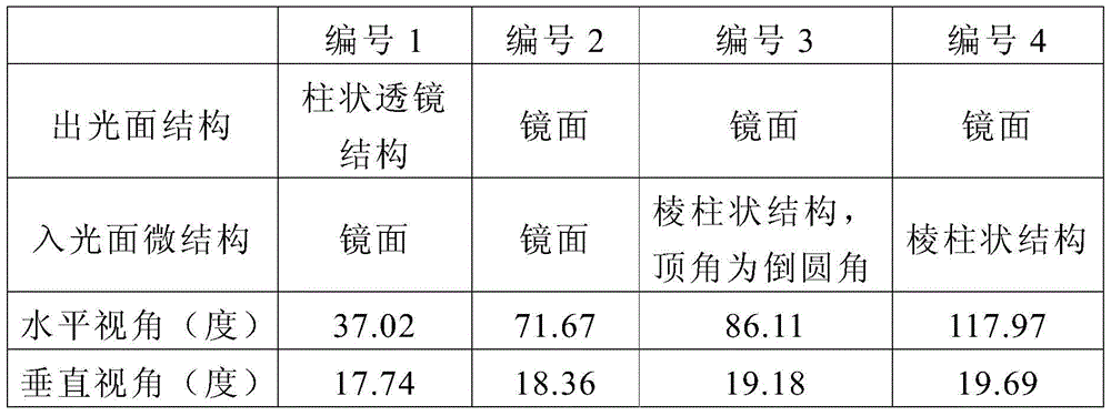
请参考表一,在本实施例中,编号1至编号4分别为具有单一导光板的光源模块的一实施例,其视角分布模拟结果。编号1的实施例对应于图6A的实施例,在编号1的实施例中,出光面结构为“柱状透镜结构”,表示其采用如图1A实施例的柱状透镜结构112于导光板的出光面。具体而言,柱状透镜结构的曲率半径为30微米,而高度为 7微米。另外,入光面微结构为“镜面”表示其导光板的入光面并不具有微结构。在本实施例的视角分布模拟结果中,光源模块的水平视角为37.02度,而光源模块的垂直视角为17.74度。另外,编号2的实施例对应于图6B的实施例,在编号2的实施例中,出光面结构为“镜面”,表示其导光板的出光面并不具有柱状透镜结构。入光面微结构为“镜面”表示其导光板的入光面并不具有微结构。在本实施例的视角分布模拟结果中,光源模块的水平视角为71.67度,而光源模块的垂直视角为18.36度。Please refer to Table 1. In this embodiment, No. 1 to No. 4 are respectively an embodiment of a light source module having a single light guide plate, and the simulation results of the viewing angle distribution. The embodiment numbered 1 corresponds to the embodiment of FIG. 6A . In the embodiment numbered 1, the light-emitting surface structure is a “cylindrical lens structure”, which means that the
另外,编号3的实施例对应于图6C的实施例,在编号3的实施例中,出光面结构为“镜面”,表示其导光板的出光面并不具有柱状透镜结构。入光面微结构为“棱柱状结构,顶角为倒圆角”表示其采用如图5B实施例的微结构516b于导光板的入光面。具体而言,微结构516b的顶角具有倒圆角,此倒圆角的曲率半径为5微米。微结构516b 的顶角的曲率半径为100微米,且微结构516b的高度为20微米。在本实施例的视角分布模拟结果中,光源模块的水平视角为86.11度,而光源模块的垂直视角为19.18度。另外,编号4的实施例对应于图 6D的实施例,在编号4的实施例中,出光面结构为“镜面”,表示其导光板的出光面并不具有柱状透镜结构。入光面微结构为“棱柱状结构”表示其采用如图5A实施例的微结构516a于导光板的入光面。具体而言,微结构516a的顶角的曲率半径为100微米,且微结构516a 的高度为20微米。在本实施例的视角分布模拟结果中,光源模块的水平视角为117.97度,而光源模块的垂直视角为19.69度。In addition, the embodiment numbered 3 corresponds to the embodiment of FIG. 6C . In the embodiment numbered 3, the light exit surface structure is a “mirror surface”, which means that the light exit surface of the light guide plate does not have a cylindrical lens structure. The microstructure of the light incident surface is “prismatic structure with rounded corners”, which means that the
图6E示出本发明另一实施例的具有单一导光板的光源模块的视角分布模拟图,图6F示出本发明又一实施例的具有单一导光板的光源模块的视角分布模拟图,图6G示出本发明再一实施例的具有单一导光板的光源模块的视角分布模拟图,而图6H示出本发明另一实施例的具有单一导光板的光源模块的视角分布模拟图。另外,以下表二举出图6E至图6H实施例中具有单一导光板的光源模块的视角分布模拟结果。具体而言,这些实施例的单一导光板的底面都具有如图3A实施例的第二底面微结构324(散射微结构MS)。需注意的是,下述的表二所列的资料并非用以限定本发明,任何熟知本技术领域的人员在参照本发明之后,当可应用本发明的原则对其参数或设定作适当的更动,以致使其设定的数据改变,然而其仍应属于本发明的范畴内。FIG. 6E shows a simulation diagram of viewing angle distribution of a light source module with a single light guide plate according to another embodiment of the present invention, FIG. 6F shows a simulation diagram of viewing angle distribution of a light source module with a single light guide plate according to another embodiment of the present invention, and FIG. 6G A simulation diagram of viewing angle distribution of a light source module with a single light guide plate according to another embodiment of the present invention is shown, and FIG. 6H is a simulation diagram of a viewing angle distribution of a light source module with a single light guide plate according to another embodiment of the present invention. In addition, Table 2 below shows the simulation results of the viewing angle distribution of the light source module with a single light guide plate in the embodiments of FIGS. 6E to 6H . Specifically, the bottom surfaces of the single light guide plates of these embodiments all have the second bottom surface microstructures 324 (scattering microstructures MS) as in the embodiment of FIG. 3A . It should be noted that the data listed in the following Table 2 are not intended to limit the present invention. Anyone skilled in the art can make appropriate parameters or settings by applying the principles of the present invention after referring to the present invention. Modification, so that the set data is changed, however, it should still belong to the scope of the present invention.
(表二)(Table II)

请参考表二,在本实施例中,编号5至编号8分别为具有单一导光板的光源模块的一实施例,其视角分布模拟结果。编号5的实施例对应于图6E的实施例,在编号5的实施例中,出光面结构为“镜面”,表示其导光板的出光面并不具有柱状透镜结构。入光面微结构为“镜面”表示其导光板的入光面并不具有微结构。在本实施例的视角分布模拟结果中,光源模块的水平视角为58.67度,而光源模块的垂直视角为26.51度。另外,编号6的实施例中,出光面结构为“镜面”,表示其导光板的出光面并不具有柱状透镜结构。入光面微结构为“棱柱状结构”表示其采用如图5A实施例的微结构516a于导光板的入光面。具体而言,微结构516a的顶角的曲率半径为100微米,且微结构516a 的高度为20微米。在本实施例的视角分布模拟结果中,光源模块的水平视角为80.77度,而光源模块的垂直视角为31.94度。Please refer to Table 2. In this embodiment,
另外,编号7的实施例对应于图6G的实施例,在编号7的实施例中,出光面结构为“镜面”,表示其导光板的出光面并不具有柱状透镜结构。入光面微结构为“棱柱状结构”表示其采用如图5A实施例的微结构516a于导光板的入光面。具体而言,微结构516a的顶角的曲率半径为20微米,且微结构516a的高度为20微米。在本实施例的视角分布模拟结果中,光源模块的水平视角为69.39度,而光源模块的垂直视角为29.73度。另外,编号8的实施例对应于图6H的实施例,在编号8的实施例中,出光面结构为“镜面”,表示其导光板的出光面并不具有柱状透镜结构。入光面微结构为“棱柱状结构,具有间距”表示其采用如图5C实施例的微结构516c于导光板的入光面。具体而言,微结构516c的顶角的曲率半径为100微米,且微结构516c的高度为20微米。相邻二微结构516c具有间距G,且间距G实质上等于各微结构516c的底面宽度Wb(如图5C所示出)。在本实施例的视角分布模拟结果中,光源模块的水平视角为65.16度,而光源模块的垂直视角为28.40度。In addition, the embodiment numbered 7 corresponds to the embodiment of FIG. 6G . In the embodiment numbered 7, the light emitting surface structure is “mirror surface”, which means that the light emitting surface of the light guide plate does not have a cylindrical lens structure. The microstructure of the light incident surface is "prismatic structure", which means that the
图7示出本发明一实施例的显示装置的剖面示意图,请参考图7。在本实施例中,显示装置700包括显示屏710以及图1A实施例的光源模块100。光源模块100用以提供光线L1以及光线L2至显示屏710。具体而言,显示屏710例如是穿透式显示屏或是其他类型的显示屏。另外,光源模块100至少也可以采用图2A实施例的光源模块200、图 3A实施例的光源模块300、图4A实施例的光源模块400或是其他类型的光源模块。另外,本实施例光源模块100的第一导光板110与第二导光板120的至少其中之一可以采用图5A实施例的导光板510a、图5B实施例的导光板510b、图5C实施例的导光板510c或是其他类型的导光板,本发明并不限于此。在本实施例中,由于这些柱状透镜结构112可以收敛来自第一光源130的光线L1的光发散角度。因此,本发明实施例的光源模块100可以选择出射光发散角度较小的光,而使显示装置700具有防窥的效果。另外,使用者可以自由地选择开启防窥模式或者广视角模式,而达到更方便的使用性。FIG. 7 is a schematic cross-sectional view of a display device according to an embodiment of the present invention. Please refer to FIG. 7 . In this embodiment, the
综上所述,本发明的实施例至少具有以下其中一个优点或功效。本发明实施例的光源模块以及显示装置中,第一导光板与第二导光板层叠设置,且第二导光板配置于第一导光板以及转向膜之间。第一光源配置于第一导光板旁,且第二光源配置于第二导光板旁。第一导光板包括第一出光面,第一出光面位于第一导光板面向转向膜的一侧且具有多个柱状透镜结构。这些柱状透镜结构沿着第一方向排列,且这些柱状透镜结构沿着与第一方向垂直的第二方向延伸。这些柱状透镜结构可以收敛来自第一光源的光线的光发散角度。因此,本发明实施例的光源模块可以选择出射光发散角度较小的光,而使显示装置具有防窥的效果。To sum up, the embodiments of the present invention have at least one of the following advantages or effects. In the light source module and the display device according to the embodiments of the present invention, the first light guide plate and the second light guide plate are stacked and disposed, and the second light guide plate is disposed between the first light guide plate and the turning film. The first light source is arranged beside the first light guide plate, and the second light source is arranged beside the second light guide plate. The first light guide plate includes a first light emitting surface, and the first light emitting surface is located on the side of the first light guide plate facing the turning film and has a plurality of cylindrical lens structures. The lenticular lens structures are arranged along a first direction, and the lenticular lens structures extend along a second direction perpendicular to the first direction. These lenticular lens structures can converge the light divergence angle of the light from the first light source. Therefore, the light source module of the embodiment of the present invention can select light with a smaller divergence angle of the emitted light, so that the display device has the effect of preventing privacy.
以上所述仅为本发明的优选实施例而已,当不能以此限定本发明实施的范围,即所有依本发明权利要求书及说明书所作的简单的等效变化与修改,都仍属本发明专利覆盖的范围内。另外本发明的任一实施例或权利要求不须实现本发明所揭露的全部目的或优点或特点。此外,摘要和发明名称仅是用来辅助专利文件检索之用,并非用来限制本发明的权利范围。此外,本说明书或权利要求书中提及的“第一”、“第二”等用语仅用以命名元件(element)的名称或区别不同实施例或范围,而并非用来限制元件数量上的上限或下限。The above descriptions are only preferred embodiments of the present invention, and should not limit the scope of implementation of the present invention, that is, all simple equivalent changes and modifications made according to the claims and the description of the present invention still belong to the patent of the present invention within the scope of coverage. Furthermore, it is not necessary for any embodiment or claim of the present invention to achieve all of the objects or advantages or features disclosed herein. In addition, the abstract and the title of the invention are only used to assist the retrieval of patent documents, not to limit the scope of rights of the present invention. In addition, the terms such as "first" and "second" mentioned in this specification or the claims are only used to name the elements or to distinguish different embodiments or ranges, and are not used to limit the number of elements. upper or lower limit.
附图标记说明Description of reference numerals
100、200、300、400:光源模块100, 200, 300, 400: light source module
110、110a、110b、110c、310、410:第一导光板110, 110a, 110b, 110c, 310, 410: first light guide plate
112、112a、112b、112c、112d、112e、112f、212:柱状透镜结构112, 112a, 112b, 112c, 112d, 112e, 112f, 212: cylindrical lens structure
114:第一底面微结构114: First Bottom Surface Microstructure
120、320、420:第二导光板120, 320, 420: the second light guide plate
124、324、424:第二底面微结构124, 324, 424: Second bottom surface microstructure
130:第一光源130: First light source
140:第二光源140: Second light source
150:转向膜150: Turning film
152:棱镜柱152: Prismatic Column
160:处理单元160: Processing Unit
510a、510b、510c:导光板510a, 510b, 510c: light guide plate
516a、516b、516c:微结构516a, 516b, 516c: Microstructures
700:显示装置700: Display device
710:显示屏710: Display
A-A’:线段A-A': line segment
BS1:第一底面BS1: First Bottom Side
BS1a:底面BS1a: Underside
BS2:第二底面BS2: Second Bottom Surface
CCS:内凹结构CCS: Concave Structure
CVS:外凸结构CVS: Convex Structure
D1:第一方向D1: first direction
D2:第二方向D2: second direction
D3:第三方向D3: third direction
ES1:第一出光面ES1: The first light-emitting surface
ES1a:出光面ES1a: light-emitting surface
ES2:第二出光面ES2: The second light-emitting surface
G:间距G: Gap
h1、h2:高度h1, h2: height
IS1:第一入光面IS1: The first light incident surface
IS1a、IS1b、IS1c:入光面IS1a, IS1b, IS1c: light incident surface
IS2:第二入光面IS2: The second light incident surface
L1、L2、L3、L4、L5、L6、L7:光线L1, L2, L3, L4, L5, L6, L7: Light
MS:散射微结构MS: Scattering Microstructure
OA1、OA2:光轴OA1, OA2: Optical axis
PS:棱柱状结构PS: Prismatic structure
S1、S3:第一表面S1, S3: first surface
S2、S4:第二表面S2, S4: second surface
SS1:第一侧表面SS1: First side surface
SS2:第二侧表面SS2: Second side surface
Wb:底面宽度Wb: Bottom width
θ1、θ2、θ3、θ4:光发散角度θ 1 , θ 2 , θ 3 , θ 4 : light divergence angles
θa:夹角角度θ a : included angle
Claims (11)
Priority Applications (2)
| Application Number | Priority Date | Filing Date | Title |
|---|---|---|---|
| CN201610131382.0A CN107179627B (en) | 2016-03-09 | 2016-03-09 | Light source module and display device |
| US15/448,613 US10705283B2 (en) | 2016-03-09 | 2017-03-03 | Light source module and display apparatus |
Applications Claiming Priority (1)
| Application Number | Priority Date | Filing Date | Title |
|---|---|---|---|
| CN201610131382.0A CN107179627B (en) | 2016-03-09 | 2016-03-09 | Light source module and display device |
Publications (2)
| Publication Number | Publication Date |
|---|---|
| CN107179627A CN107179627A (en) | 2017-09-19 |
| CN107179627B true CN107179627B (en) | 2020-10-23 |
Family
ID=59788596
Family Applications (1)
| Application Number | Title | Priority Date | Filing Date |
|---|---|---|---|
| CN201610131382.0A Active CN107179627B (en) | 2016-03-09 | 2016-03-09 | Light source module and display device |
Country Status (2)
| Country | Link |
|---|---|
| US (1) | US10705283B2 (en) |
| CN (1) | CN107179627B (en) |
Cited By (1)
| Publication number | Priority date | Publication date | Assignee | Title |
|---|---|---|---|---|
| US12228763B2 (en) | 2022-10-12 | 2025-02-18 | Darwin Precisions Corporation | Switchable backlight module |
Families Citing this family (27)
| Publication number | Priority date | Publication date | Assignee | Title |
|---|---|---|---|---|
| CN108292062B (en) | 2015-11-27 | 2019-12-13 | 矽光学有限公司 | Displays for free-running and restricted-running modes |
| DE102017006285A1 (en) | 2017-06-30 | 2019-01-03 | Sioptica Gmbh | Screen for a free and restricted view mode |
| DE102017007669A1 (en) | 2017-08-14 | 2019-02-14 | Sioptica Gmbh | Free and restricted viewing mode screen and use of same |
| TWI649592B (en) * | 2018-01-15 | 2019-02-01 | 友達光電股份有限公司 | Display device |
| CN108363241B (en) * | 2018-02-12 | 2021-06-29 | 深圳创维-Rgb电子有限公司 | A backlight module and a liquid crystal display having the backlight module |
| CN108397701A (en) * | 2018-03-02 | 2018-08-14 | 深圳创维-Rgb电子有限公司 | A kind of backlight module and display equipment |
| CN110568657A (en) * | 2018-06-05 | 2019-12-13 | 中强光电股份有限公司 | display device |
| CN108897092B (en) * | 2018-09-03 | 2020-06-02 | 合肥京东方光电科技有限公司 | Light guide structure, manufacturing method thereof, light source assembly and display device |
| CN110308512B (en) * | 2019-07-30 | 2020-09-29 | 昆山龙腾光电股份有限公司 | Backlight module, display device and manufacturing method of light guide plate |
| CN110658583A (en) * | 2019-11-06 | 2020-01-07 | 合肥京东方光电科技有限公司 | Light guide plate, backlight module and display device |
| CN111158188B (en) * | 2020-01-03 | 2022-06-24 | 京东方科技集团股份有限公司 | A display panel and display device |
| CN111176016B (en) * | 2020-01-07 | 2022-10-18 | 京东方科技集团股份有限公司 | Backlight module and display device |
| FI20206056A1 (en) * | 2020-10-26 | 2022-04-27 | Teknologian Tutkimuskeskus Vtt Oy | Screen with a selectable visual sector |
| CN112882286A (en) * | 2020-12-15 | 2021-06-01 | 马鞍山晶智科技有限公司 | Peep-proof backlight module |
| WO2022168407A1 (en) * | 2021-02-05 | 2022-08-11 | 株式会社ジャパンディスプレイ | Illumination device and display device |
| EP4314638A1 (en) | 2021-03-30 | 2024-02-07 | Sioptica GmbH | Lighting device for a free viewing mode and a restricted viewing mode |
| WO2022222083A1 (en) * | 2021-04-21 | 2022-10-27 | 京东方科技集团股份有限公司 | Backlighting module and display apparatus |
| CN115561854B (en) * | 2021-07-02 | 2025-08-26 | 瀚宇彩晶股份有限公司 | Anti-peeping backlight module |
| WO2023279224A1 (en) * | 2021-07-05 | 2023-01-12 | 瑞仪光电(苏州)有限公司 | Backlight module and display apparatus |
| CN115576133A (en) * | 2021-07-05 | 2023-01-06 | 瑞仪光电(苏州)有限公司 | Backlight module and display device |
| CN113655559B (en) * | 2021-09-06 | 2022-12-13 | 扬昕科技(苏州)有限公司 | Light-collecting light guide plate and display device |
| KR102522095B1 (en) | 2021-09-29 | 2023-04-17 | 엘지디스플레이 주식회사 | Display Device |
| CN116774480A (en) * | 2022-03-08 | 2023-09-19 | 海信视像科技股份有限公司 | Display device |
| US12130463B2 (en) | 2022-03-25 | 2024-10-29 | Beijing Boe Display Technology Co., Ltd. | Backlight module and display device |
| CN114967224B (en) * | 2022-04-07 | 2024-01-30 | 武汉华星光电技术有限公司 | Backlight module and display device |
| CN117538975A (en) * | 2022-08-02 | 2024-02-09 | 苏州佳世达电通有限公司 | Display device |
| CN118778283A (en) * | 2024-05-07 | 2024-10-15 | 达运精密工业股份有限公司 | Backlight module and naked-eye stereoscopic display device using the same |
Family Cites Families (45)
| Publication number | Priority date | Publication date | Assignee | Title |
|---|---|---|---|---|
| US5897184A (en) * | 1996-07-02 | 1999-04-27 | Dimension Technologies, Inc. | Reduced-thickness backlighter for autostereoscopic display and display using the backlighter |
| TW518440B (en) * | 1998-03-25 | 2003-01-21 | Enplas Corp | Surface light source device of side light type and liquid crystal display |
| JP3452137B2 (en) * | 2001-02-09 | 2003-09-29 | オムロン株式会社 | Light guide plate, surface light source device, image display device, mobile phone, and information terminal |
| TWI257015B (en) * | 2002-12-20 | 2006-06-21 | Hon Hai Prec Ind Co Ltd | Light guide plate and back light system with the same |
| GB2410116A (en) * | 2004-01-17 | 2005-07-20 | Sharp Kk | Illumination system and display device |
| JP4485999B2 (en) * | 2004-07-09 | 2010-06-23 | スタンレー電気株式会社 | Surface light source device |
| TWI263845B (en) | 2004-11-19 | 2006-10-11 | Au Optronics Corp | Viewing-angle adjustable liquid crystal display and method of the same |
| JP4533728B2 (en) * | 2004-11-29 | 2010-09-01 | 株式会社 日立ディスプレイズ | Liquid crystal display |
| CN100410767C (en) * | 2005-01-28 | 2008-08-13 | 友达光电股份有限公司 | Backlight assembly and stereoscopic image imaging apparatus and method using the same |
| JP4771065B2 (en) * | 2005-09-30 | 2011-09-14 | ゲットナー・ファンデーション・エルエルシー | Light source device, display device, and terminal device |
| TWI321694B (en) | 2005-12-23 | 2010-03-11 | Innolux Display Corp | Backlight module and liquid crystal display module |
| CN100498389C (en) * | 2006-03-25 | 2009-06-10 | 鸿富锦精密工业(深圳)有限公司 | Light conducting plate and back light module |
| US7478913B2 (en) * | 2006-11-15 | 2009-01-20 | 3M Innovative Properties | Back-lit displays with high illumination uniformity |
| JP4748684B2 (en) * | 2006-11-15 | 2011-08-17 | シチズン電子株式会社 | Backlight unit and display device |
| CN100582831C (en) * | 2006-12-22 | 2010-01-20 | 鸿富锦精密工业(深圳)有限公司 | Light conducting plate and back light module unit |
| JP4513918B2 (en) * | 2008-06-03 | 2010-07-28 | エプソンイメージングデバイス株式会社 | Illumination device and electro-optical device |
| CN101684927B (en) * | 2008-09-22 | 2011-11-16 | 财团法人工业技术研究院 | High-collimation direct light source module and light emitting method thereof |
| JP5143770B2 (en) * | 2009-03-02 | 2013-02-13 | 株式会社ジャパンディスプレイイースト | Liquid crystal display |
| CN102472456A (en) * | 2009-11-30 | 2012-05-23 | 夏普株式会社 | Planar lighting device and display device having same |
| DE112010004660T5 (en) * | 2009-12-02 | 2012-10-11 | Mitsubishi Electric Corporation | Liquid crystal display device |
| CN102168841A (en) * | 2010-02-26 | 2011-08-31 | 中强光电股份有限公司 | Light guide plate and backlight module |
| TWI429971B (en) | 2010-04-27 | 2014-03-11 | Univ Nat Kaohsiung 1St Univ Sc | Integral light guide plate with axial light collection effect |
| KR101747297B1 (en) * | 2010-08-04 | 2017-06-27 | 삼성전자주식회사 | Backlight unit and 2D and 3D image display system |
| JP4825926B1 (en) * | 2010-10-29 | 2011-11-30 | 株式会社東芝 | Display device |
| KR20120110446A (en) * | 2011-03-29 | 2012-10-10 | 삼성디스플레이 주식회사 | Back-light unit, method of fabricating the same and display apparutus having back-light unit |
| JP2012215666A (en) * | 2011-03-31 | 2012-11-08 | Panasonic Corp | Image display device, and computer device using the same |
| WO2012144449A1 (en) * | 2011-04-22 | 2012-10-26 | シャープ株式会社 | Backlight unit and display device |
| JP5649526B2 (en) * | 2011-07-01 | 2015-01-07 | 株式会社ジャパンディスプレイ | Display device |
| US8797480B2 (en) * | 2011-10-18 | 2014-08-05 | Dai Nippon Printing Co., Ltd. | Light guide plate, surface light source device, and display device |
| TWI485453B (en) * | 2014-01-02 | 2015-05-21 | Radiant Opto Electronics Corp | Light guide plate |
| TWI481915B (en) * | 2013-08-20 | 2015-04-21 | Radiant Opto Electronics Corp | Light guide plate with multidirectional structures |
| TWI539211B (en) * | 2012-04-30 | 2016-06-21 | 中強光電股份有限公司 | Light guide plate and backlight module using the same |
| KR101481677B1 (en) * | 2012-11-30 | 2015-01-13 | 엘지디스플레이 주식회사 | Back Light Unit and Liquid Crystal Display device Comprising The Same And Fabricating Method thereof |
| US20160054507A1 (en) * | 2013-03-29 | 2016-02-25 | Sharp Kabushiki Kaisha | Lighting device and display device |
| TWI507786B (en) | 2013-05-09 | 2015-11-11 | Chi Lin Optoelectronics Co Ltd | Display apparatus and side edge type backlight module thereof |
| CN103292219A (en) * | 2013-06-04 | 2013-09-11 | 北京京东方光电科技有限公司 | Backlight module and display device |
| CA2917851C (en) * | 2013-06-13 | 2017-07-11 | Kuraray Co., Ltd. | Lighting device |
| JP2015090959A (en) * | 2013-11-07 | 2015-05-11 | ソニー株式会社 | Light-emitting device and display device |
| JP6586092B2 (en) * | 2013-12-19 | 2019-10-02 | コーニング インコーポレイテッド | Relief surface for display applications |
| CN104848052A (en) * | 2014-02-13 | 2015-08-19 | 扬升照明股份有限公司 | Backlight module |
| CN104932140B (en) * | 2014-03-21 | 2017-12-26 | 扬升照明股份有限公司 | Backlight module |
| WO2016017492A1 (en) * | 2014-07-29 | 2016-02-04 | シャープ株式会社 | Illumination device and display device |
| US20170010407A1 (en) * | 2015-07-09 | 2017-01-12 | Apple Inc. | Displays With Multimode Backlight Units |
| TWI589957B (en) * | 2015-07-15 | 2017-07-01 | 友達光電股份有限公司 | Peep-proof display system and display method thereof |
| KR20170079443A (en) * | 2015-12-30 | 2017-07-10 | 엘지디스플레이 주식회사 | Backlight unit and autostereoscopic 3d display device including the same |
-
2016
- 2016-03-09 CN CN201610131382.0A patent/CN107179627B/en active Active
-
2017
- 2017-03-03 US US15/448,613 patent/US10705283B2/en active Active
Cited By (1)
| Publication number | Priority date | Publication date | Assignee | Title |
|---|---|---|---|---|
| US12228763B2 (en) | 2022-10-12 | 2025-02-18 | Darwin Precisions Corporation | Switchable backlight module |
Also Published As
| Publication number | Publication date |
|---|---|
| US10705283B2 (en) | 2020-07-07 |
| US20170261672A1 (en) | 2017-09-14 |
| CN107179627A (en) | 2017-09-19 |
Similar Documents
| Publication | Publication Date | Title |
|---|---|---|
| CN107179627B (en) | Light source module and display device | |
| US10816834B2 (en) | Backlight module, display device and driving method thereof | |
| US9709722B2 (en) | Backlight module having a prism structure | |
| CN211236517U (en) | Backlight module and display device | |
| US10008164B2 (en) | Variable viewing angle optical systems | |
| TWI729317B (en) | Light guide plate and backlight module using the same | |
| US20080266904A1 (en) | Optical film having a surface with rounded structures | |
| CN207301564U (en) | Light source module | |
| US20070035940A1 (en) | Direct backlight module | |
| CN111527344A (en) | Mode-selectable backlight panel, privacy display and method | |
| US20240192434A1 (en) | Anti-peep light source module and anti-peep display device | |
| US9952373B2 (en) | Light source module and display apparatus | |
| US7199930B2 (en) | Light modulation element | |
| TWM628809U (en) | Backlight module and display apparatus | |
| US20220043303A1 (en) | Light source module and dual display device | |
| US9442242B2 (en) | Backlight module and liquid crystal display | |
| US9964682B2 (en) | Light source module and display apparatus | |
| CN116300209A (en) | Backlight module and display device thereof | |
| US8118469B2 (en) | Surface illuminating device and image display apparatus | |
| US20180003886A1 (en) | Ligth source module and light guide plate | |
| CN117950223A (en) | Light source module and display device | |
| TWI657277B (en) | Display device | |
| US10942393B2 (en) | Light source assembly, backlight module and display device | |
| TW202417955A (en) | Light source module and display device | |
| CA2820819C (en) | Backlight module having a prism structure |
Legal Events
| Date | Code | Title | Description |
|---|---|---|---|
| PB01 | Publication | ||
| PB01 | Publication | ||
| SE01 | Entry into force of request for substantive examination | ||
| SE01 | Entry into force of request for substantive examination | ||
| TA01 | Transfer of patent application right | ||
| TA01 | Transfer of patent application right |
Effective date of registration: 20181224 Address after: Hsinchu Science Park, Taiwan, China Applicant after: Coretronic Corp. Address before: Hsinchu Science Park, Taiwan, China Applicant before: Yangsheng Lighting Co.,Ltd. |
|
| TA01 | Transfer of patent application right | ||
| TA01 | Transfer of patent application right |
Effective date of registration: 20190402 Address after: Taiwan County, Hsinchu, China Hukou Feng Village Road, No. 5 Culture Applicant after: Taiwan young Co.,Ltd. Address before: Hsinchu Science Park, Taiwan, China Applicant before: Coretronic Corp. |
|
| GR01 | Patent grant | ||
| GR01 | Patent grant | ||
| TR01 | Transfer of patent right | ||
| TR01 | Transfer of patent right |
Effective date of registration: 20240106 Address after: Hsinchu Science Park, Taiwan, China, No. 11 Li Li Road, Hsinchu Patentee after: Coretronic Corp. Address before: Taiwan County, Hsinchu, China Hukou Feng Village Road, No. 5 Culture Patentee before: Taiwan young Co.,Ltd. |