CN107168305B - Bezier and VFH-based unmanned vehicle track planning method under intersection scene - Google Patents
Bezier and VFH-based unmanned vehicle track planning method under intersection scene Download PDFInfo
- Publication number
- CN107168305B CN107168305B CN201710214224.6A CN201710214224A CN107168305B CN 107168305 B CN107168305 B CN 107168305B CN 201710214224 A CN201710214224 A CN 201710214224A CN 107168305 B CN107168305 B CN 107168305B
- Authority
- CN
- China
- Prior art keywords
- trajectory
- point
- sector
- curve
- bezier
- Prior art date
- Legal status (The legal status is an assumption and is not a legal conclusion. Google has not performed a legal analysis and makes no representation as to the accuracy of the status listed.)
- Expired - Fee Related
Links
Images


Classifications
-
- G—PHYSICS
- G05—CONTROLLING; REGULATING
- G05D—SYSTEMS FOR CONTROLLING OR REGULATING NON-ELECTRIC VARIABLES
- G05D1/00—Control of position, course, altitude or attitude of land, water, air or space vehicles, e.g. using automatic pilots
- G05D1/02—Control of position or course in two dimensions
- G05D1/021—Control of position or course in two dimensions specially adapted to land vehicles
- G05D1/0212—Control of position or course in two dimensions specially adapted to land vehicles with means for defining a desired trajectory
- G05D1/0217—Control of position or course in two dimensions specially adapted to land vehicles with means for defining a desired trajectory in accordance with energy consumption, time reduction or distance reduction criteria
Landscapes
- Engineering & Computer Science (AREA)
- Aviation & Aerospace Engineering (AREA)
- Radar, Positioning & Navigation (AREA)
- Remote Sensing (AREA)
- Physics & Mathematics (AREA)
- General Physics & Mathematics (AREA)
- Automation & Control Theory (AREA)
- Control Of Position, Course, Altitude, Or Attitude Of Moving Bodies (AREA)
Abstract
本发明提供一种路口场景下基于Bezier和VFH的无人车轨迹规划方法。包括:1)获取本次轨迹规划的起始点位姿P0(x0,y0,θ0)和目标点位姿P3(x3,y3,θ3);2)采用三阶Bezier曲线模型生成从起始点P0到目标点P3的轨迹簇A1;3)依据最大曲率约束对轨迹簇进行筛选得到轨迹簇A2,对A2进行碰撞检测,得到无碰轨迹簇A3;4)若A3非空,在A3中依据轨迹最平滑原则选择最优轨迹输出给控制层,结束;否则,转步骤5;5)对原始VFH算法中的活动区域进行改善,建立扇形活动区域;6)利用障碍物信息建立栅格图;7)将扇形活动区域划分成多个扇区,判断是否有障碍物;8)与Bezier曲线相结合选择最优轨迹点;9)步骤8生成的离散点集做控制点生成B样条曲线作为无人车最终轨迹。

The present invention provides a trajectory planning method for unmanned vehicles based on Bezier and VFH in an intersection scene. Including: 1) Obtain the starting point pose P 0 (x 0 , y 0 , θ 0 ) and the target point pose P 3 (x 3 , y 3 , θ 3 ) of this trajectory planning; 2) Use the third-order Bezier The curve model generates the trajectory cluster A 1 from the starting point P 0 to the target point P 3 ; 3) According to the maximum curvature constraint, the trajectory cluster is screened to obtain the trajectory cluster A 2 , and the collision detection is performed on A 2 to obtain the collision-free trajectory cluster A 3 4) If A 3 is not empty, select the optimal trajectory to output to the control layer according to the principle of the smoothest trajectory in A 3 , and end; otherwise, go to step 5; 5) Improve the active area in the original VFH algorithm, and establish a sector Active area; 6) Use obstacle information to build a grid map; 7) Divide the sector-shaped active area into multiple sectors to determine whether there are obstacles; 8) Combine with Bezier curve to select the optimal trajectory point; 9) Step 8 The generated discrete point set is used as the control point to generate a B-spline curve as the final trajectory of the unmanned vehicle.
Description
技术领域technical field
本发明涉及智能交通系统技术领域,特别涉及无人驾驶车辆在路口这样的复杂交通场景下的实时轨迹规划方法。The invention relates to the technical field of intelligent transportation systems, and in particular, to a real-time trajectory planning method for unmanned vehicles in complex traffic scenarios such as intersections.
背景技术Background technique
随着汽车产业和计算机技术的飞速发展,无人驾驶车辆在机器人领域里取得了空前的进步。决策系统做为无人驾驶车辆的“大脑”,在感知系统认知周围环境后,需要做出安全可执行的决策,确定当前的有效行为及行为的目标状态,然后规划运动轨迹。路口是交通网络拓扑结构的节点,是交通事故的频发地段。所以,解决无人车在路口处的轨迹规划问题意义重大。经典的轨迹规划方法分为两大类,一类是直接有解析解,基于多项式、正弦曲线、回旋曲线、Bezier曲线等方法确定参数直接生成轨迹的解析解;第二类方法是基于采样的方式生成由离散点组成的轨迹,有A*、RRT、人工势场法,VFH等多种方法解决不同环境中的轨迹规划问题。With the rapid development of the automobile industry and computer technology, unmanned vehicles have made unprecedented progress in the field of robotics. As the "brain" of an unmanned vehicle, the decision-making system needs to make safe and executable decisions after perceiving the system's cognition of the surrounding environment, determine the current effective behavior and the target state of the behavior, and then plan the movement trajectory. The intersection is the node of the topological structure of the traffic network and the frequent traffic accident area. Therefore, it is of great significance to solve the trajectory planning problem of unmanned vehicles at intersections. Classical trajectory planning methods are divided into two categories, one is the analytical solution that directly has an analytical solution, and the parameters are determined based on polynomial, sinusoidal, clothoid, Bezier curve and other methods to directly generate the analytical solution of the trajectory; the second method is based on sampling. To generate trajectories composed of discrete points, there are A*, RRT, artificial potential field method, VFH and other methods to solve trajectory planning problems in different environments.
Bezier是解析法生成轨迹的典型方法。其优点是在无障碍物或者障碍物稀疏时,生成轨迹快且平滑性好。缺点在于障碍物密集时难于通过调整参数获得有效轨迹[1]。Bezier is a typical method for generating trajectories analytically. Its advantage is that when there are no obstacles or sparse obstacles, the generated trajectory is fast and smooth. The disadvantage is that it is difficult to obtain an effective trajectory by adjusting the parameters when the obstacles are dense [1].
A*算法是经典的运动规划算法,其优点是具有启发性,能够较快的得到全局最优轨迹,然而其搜索步长难以确定,在复杂并且范围较大的规划环境中效率低下[2]。The A* algorithm is a classic motion planning algorithm. Its advantage is that it is enlightening and can quickly obtain the global optimal trajectory. However, its search step size is difficult to determine, and it is inefficient in a complex and large-scale planning environment [2] .
RRT算法是由美国UIUC教授S.M.LaValle提出的,该算法在扩展节点时考虑了运动系统的运动学微分方程约束,因此,生成的运动轨迹满足全局最优约束和系统自身微分约束,可见,RRT算法可以很好的解决高维度、动态环境、含有微分约束的运动规划问题,然而,其需要确定的参数数量较多,要达到比较好的规划效果,往往难度较大[3]。The RRT algorithm was proposed by S.M.LaValle, a professor at UIUC in the United States. The algorithm considers the kinematics differential equation constraints of the kinematic system when expanding nodes. Therefore, the generated motion trajectory satisfies the global optimal constraints and the system's own differential constraints. It can be seen that the RRT algorithm It can well solve motion planning problems with high dimensions, dynamic environments, and differential constraints. However, it requires a large number of parameters to be determined, and it is often difficult to achieve a better planning effect [3].
人工势场法是轨迹规划算法中较成熟且高效的规划方法,它将环境信息转化为引力场和斥力场模型。人工势场法的一个缺陷就是当目标在障碍物的影响范围内时,整个势场中除目标点外还可能存在其它的局部极小点,机器人可能陷入局部极小点而不能达到目标点。此外,轨迹经过障碍物附近时由于合力方向变化产生抖动现象。Artificial potential field method is a more mature and efficient planning method in trajectory planning algorithm, which converts environmental information into gravitational and repulsive field models. A defect of the artificial potential field method is that when the target is within the influence range of the obstacle, there may be other local minima in the whole potential field besides the target point, and the robot may fall into the local minima and cannot reach the target point. In addition, when the trajectory passes near the obstacle, the jitter phenomenon occurs due to the change of the direction of the resultant force.
VFH算法将机器人的工作环境分解为具有二值信息的栅格单元,每个矩形栅格中有一个累积值,表示在此处存在障碍物的可信度,高的累积值表示存在障碍物的可信度高。栅格选得小,环境信息存储量大,决策速度慢;栅格选得大,环境分辨率下降,在障碍物环境中发现轨迹的能力减弱[4]。The VFH algorithm decomposes the working environment of the robot into grid cells with binary information. There is a cumulative value in each rectangular grid, indicating the reliability of the existence of obstacles here, and a high cumulative value indicates the existence of obstacles. High reliability. If the grid is selected small, the storage capacity of environmental information will be large, and the decision-making speed will be slow; if the grid is selected large, the environmental resolution will be reduced, and the ability to find trajectories in the obstacle environment will be weakened [4].
VFH算法具有很强的避障能力,能够在复杂多障碍物环境中找到无碰撞的运动轨迹;在路口这样复杂的环境下适合使用栅格图进行环境建模,而VFH算法恰好是基于障碍物栅格表示的运动规划方法;VFH算法的规划空间是连续的,这方便将车辆的运动学约束加进来[5]。The VFH algorithm has strong obstacle avoidance ability and can find collision-free motion trajectories in complex multi-obstacle environments; it is suitable to use grid maps for environmental modeling in complex environments such as intersections, and the VFH algorithm happens to be based on obstacles. The motion planning method represented by the grid; the planning space of the VFH algorithm is continuous, which facilitates the addition of the kinematic constraints of the vehicle [5].
然而,VFH算法是为移动机器人设计的,直接使用在无人驾驶车辆上往往达不到预期的目标,主要有以下三个问题:原始VFH算法是一种基于感知数据的实时运动规划方法,直接使用必然导致运动轨迹不平滑而出现“震荡”现象[6];原始VFH算法活动区域中的部分运动状态点对无人驾驶车辆来讲是不可达的;VFH算法得到的是稀疏的位置点集,缺乏其它运动状态信息,不能引导车辆行驶[7]。However, the VFH algorithm is designed for mobile robots, and it often fails to achieve the expected goals when used directly on unmanned vehicles. There are three main problems: the original VFH algorithm is a real-time motion planning method based on perception data. Using it will inevitably lead to the unsmooth motion trajectory and the phenomenon of "oscillation" [6]; some motion state points in the active area of the original VFH algorithm are unreachable for unmanned vehicles; the VFH algorithm obtains a sparse set of position points , lack of other motion state information, can not guide the vehicle [7].
以下给出检索的相关文献:The relevant literature searched is given below:
[1]L.Han,H.Yashiro,H.T.N.Nejad,Q.H.Do,and S.Mita,“Bezier curve basedpath planning for autonomous vehicle in urban environment,”in 2010IEEEIntelligent Vehicles Symposium(IV).IEEE,2010,pp.1036–1042.[1] L.Han, H.Yashiro, H.T.N.Nejad, Q.H.Do, and S.Mita, "Bezier curve basedpath planning for autonomous vehicles in urban environment," in 2010IEEEIntelligent Vehicles Symposium(IV).IEEE,2010,pp.1036 –1042.
[2]Huyn N,Dechter R,Pearl J.Probabilistic analysis of the complexityof A*[J].Artificial Intelligence,1980.15(3):241~254.[2] Huyn N, Dechter R, Pearl J. Probabilistic analysis of the complexity of A*[J].Artificial Intelligence,1980.15(3):241~254.
[3]La Valle S M,Kuffner J J.Rapidly-exploring random trees:Progressand prospects[C]//4th International Workshop on Algorithmic Foundation ofRobotics.Wellesley,USA:A K Pe-ters,2000:293-308.[3] La Valle S M, Kuffner J J. Rapidly-exploring random trees: Progress and prospects [C]//4th International Workshop on Algorithmic Foundation of Robotics. Wellesley, USA: A K Pe-ters, 2000: 293-308.
[4]J.Borenstein and Y.Koren,“The vector field histogram-fast obstacleavoidance for mobile robots,”IEEE Transactions on Robotics and Automation,vol.7,no.3,pp.278–288,1991.[4] J. Borenstein and Y. Koren, "The vector field histogram-fast obstacleavoidance for mobile robots," IEEE Transactions on Robotics and Automation, vol.7, no.3, pp.278–288, 1991.
[5]I.Ulrich and J.Borenstein,“VFH+:Reliable obstacle avoidance forfast mobile robots,”in 1998IEEE International Conference on Robotics andAutomation.IEEE,1998,pp.1572–1577.[5] I. Ulrich and J. Borenstein, "VFH+: Reliable obstacle avoidance for fast mobile robots," in 1998IEEE International Conference on Robotics and Automation.IEEE, 1998, pp.1572–1577.
[6]I.Ulrich and J.Borenstein,“VFH*:Local obstacle avoidance withlook-ahead verification,”in 2000IEEE International Conference on Robotics andAutomation.IEEE,2000,pp.2505–2511.[6] I. Ulrich and J. Borenstein, "VFH*: Local obstacle avoidance with look-ahead verification," in 2000 IEEE International Conference on Robotics and Automation. IEEE, 2000, pp. 2505–2511.
[7]D.Jiea,M.Xueming,and P.Kaixiang,“IVFH*:Real-time dynamic obstacleavoidance for mobile robots,”in 2010 11th International Conference on ControlAutomation Robotics and Vision(ICARCV).IEEE,2010,pp.844–847.[7]D.Jiea,M.Xueming,and P.Kaixiang,“IVFH*:Real-time dynamic obstacleavoidance for mobile robots,”in 2010 11th International Conference on ControlAutomation Robotics and Vision(ICARCV).IEEE,2010,pp. 844–847.
发明内容SUMMARY OF THE INVENTION
本发明的目的在于提供一种路口场景下基于Bezier曲线和VFH方法的无人车实时轨迹规划方法,解决上述现有理论与技术上存在的缺陷或不足。本发明用三阶Bezier曲线做为无人驾驶车辆的行驶轨迹;同时对传统VFH算法做出改进,将VFH算法和Bezier曲线相结合,克服VFH算法的缺陷;并且用分层的思想将两种运动规划方法同时用于路口的轨迹规划,划分优先级。The purpose of the present invention is to provide a real-time trajectory planning method for unmanned vehicles based on the Bezier curve and the VFH method in the intersection scene, so as to solve the above-mentioned defects or deficiencies in the existing theory and technology. The invention uses the third-order Bezier curve as the driving track of the unmanned vehicle; at the same time, it improves the traditional VFH algorithm by combining the VFH algorithm and the Bezier curve to overcome the defects of the VFH algorithm; The motion planning method is also used for the trajectory planning of intersections and prioritization.
为达到用三阶Bezier曲线做轨迹规划,本发明采用了以下技术方案:In order to achieve trajectory planning with third-order Bezier curves, the present invention has adopted the following technical solutions:
1、路口场景下基于Bezier曲线和VFH方法的无人车实时轨迹规划方法,包括以下步骤:1. A real-time trajectory planning method for unmanned vehicles based on Bezier curve and VFH method in intersection scene, including the following steps:
步骤一,从行为决策层获取当前行为方式及本次轨迹规划的起始点位姿P0(x0,y0,θ0)和目标点位姿P3(x3,y3,θ3);Step 1: Obtain the current behavior mode and the starting point pose P 0 (x 0 , y 0 , θ 0 ) and the target point pose P 3 (x 3 , y 3 , θ 3 ) from the behavior decision layer for this trajectory planning ;
步骤二,采用三阶Bezier曲线模型生成从起始点P0到目标点P3的轨迹簇A1采用三阶Bezier曲线模型生成从起始点P0到目标点P3的轨迹簇A1,选择4个控制点的三阶Bezier曲线进行规划,根据车辆端点处的最小转弯半径求出P0P1和P2P3的下限,同时我们依据线段|P0P3|的长度确定P0P1和P2P3的上限,在得到控制点P1和P2的范围后,在范围内等间隔离散的取多个不同的P1和P2,得到多组控制点,进而得到多条满足端点曲率约束的几何轨迹,称之为轨迹簇,用A1表示。Step 2: Use the third-order Bezier curve model to generate the trajectory cluster A 1 from the starting point P 0 to the target point P 3 Use the third-order Bezier curve model to generate the trajectory cluster A 1 from the starting point P 0 to the target point P 3 , select 4 The third-order Bezier curve of the three control points is planned, and the lower limits of P 0 P 1 and P 2 P 3 are obtained according to the minimum turning radius at the end of the vehicle. At the same time, we determine P 0 P 1 according to the length of the line segment |P 0 P 3 | and the upper limit of P 2 P 3 , after obtaining the range of control points P 1 and P 2 , discretely take multiple different P 1 and P 2 at equal intervals within the range to obtain multiple sets of control points, and then obtain multiple satisfying End-point curvature-constrained geometric trajectories, called trajectories clusters, denoted by A 1 .
步骤三,在得到满足曲率约束的轨迹之后,进行碰撞检测,得到无碰轨迹簇A3。若无碰轨迹簇非空,则顺序进行步骤四。若无碰轨迹簇为空,进入步骤五;Step 3: After obtaining a trajectory satisfying the curvature constraint, perform collision detection to obtain a collision-free trajectory cluster A 3 . If the no-touch track cluster is not empty, proceed to step 4 in sequence. If the no-touch track cluster is empty, go to step 5;
步骤四,选择最优轨迹Step 4: Select the optimal trajectory
在得到满足曲率约束并无碰的轨迹之后,我们需要进一步选择最优轨迹。以轨迹最平滑为标准选择最优轨迹,可抽象成After obtaining the trajectory that satisfies the curvature constraint and has no collisions, we need to further select the optimal trajectory. The optimal trajectory is selected based on the smoothest trajectory, which can be abstracted into

步骤五,对原始VFH算法中的活动区域进行改善Step 5: Improve the active area in the original VFH algorithm
rmin表示车辆的最小转弯半径,s表示车辆行进过程中的搜索步长;r min represents the minimum turning radius of the vehicle, and s represents the search step in the process of the vehicle traveling;
步骤六,利用障碍物信息建立栅格图Step 6: Create a grid map using obstacle information
由于障碍物被抽象成一个box,收到的障碍物信息是box的四个角点坐标,因此可根据四个角点建立栅格图,以栅格图正中心为原点建立坐标系,将box的四个角点坐标映射到栅格图坐标系中;Since the obstacle is abstracted into a box, the received obstacle information is the coordinates of the four corner points of the box, so a grid map can be established based on the four corner points, and a coordinate system can be established with the center of the grid map as the origin, and the box The coordinates of the four corners of the map are mapped to the grid coordinate system;
步骤七,将扇形活动区域划分成多个扇区,并判断是否有障碍物占据Step 7: Divide the sector-shaped active area into multiple sectors, and determine whether there are obstacles occupied
对于栅格图上每一个被障碍物占据的栅格,将它们抽象成一个质点,判断该栅格是否落入扇形区域中;若落入,判断是落入到哪一个扇区中,否则认为该障碍物目前不在搜索范围内,最终对每个扇区的被障碍物占据的栅格个数做出统计;For each grid occupied by obstacles on the grid map, abstract them into a mass point, and judge whether the grid falls into the sector area; if it falls, judge which sector it falls into, otherwise consider it The obstacle is not currently in the search range, and finally count the number of grids occupied by obstacles in each sector;
步骤八,与Bezier曲线相结合选择最优轨迹点Step 8, combine with Bezier curve to select the optimal trajectory point
如果有多个扇区都是可行的,那么将选择一个最优的扇区所对应的轨迹点,这里主要有两个约束条件来筛选出最优轨迹点。一是考虑车宽,二是考虑目标点位姿。If multiple sectors are feasible, then the trajectory point corresponding to an optimal sector will be selected. There are mainly two constraints to filter out the optimal trajectory point. One is to consider the width of the vehicle, and the other is to consider the pose of the target point.
步骤九,离散点集做控制点生成B样条曲线Step 9: Discrete point set as control point to generate B-spline curve
B样条的数学模型描述如下:The mathematical model of B-splines is described as follows:


式中,Pi,n(t)表示第i+1个n阶B样条曲线片段;n表示B样条曲线的阶数;t为参数,取值为[0,1];Pi+k为控制点;Fk,n(t)为B样条基函数。In the formula, P i,n (t) represents the i+1th n-order B-spline curve segment; n represents the order of the B-spline curve; t is a parameter, which takes the value [0,1]; P i+ k is the control point; F k,n (t) is the B-spline basis function.
所述的采用三阶Bezier曲线模型生成从起始点P0到目标点P3的轨迹簇A1,选择4个控制点的三阶Bezier曲线进行规划,根据车辆端点处的最小转弯半径求出P0P1和P2P3的下限,同时我们依据线段|P0P3|的长度确定P0P1和P2P3的上限,在得到控制点P1和P2的范围后,在范围内等间隔离散的取多个不同的P1和P2,得到多组控制点,进而得到多条满足端点曲率约束的几何轨迹,称之为轨迹簇,用A1表示。The third-order Bezier curve model is used to generate the trajectory cluster A 1 from the starting point P 0 to the target point P 3 , the third-order Bezier curve of 4 control points is selected for planning, and P is obtained according to the minimum turning radius at the vehicle end point. 0 The lower limit of P 1 and P 2 P 3 , and we determine the upper limit of P 0 P 1 and P 2 P 3 according to the length of the line segment |P 0 P 3 |, after obtaining the range of control points P 1 and P 2 , in Take multiple different P 1 and P 2 discretely at equal intervals within the range to obtain multiple sets of control points, and then obtain multiple geometric trajectories that satisfy the endpoint curvature constraints, which are called trajectory clusters and are represented by A 1 .
与Bezier曲线相结合选择最优轨迹点,使其逼近目标点位姿并且轨迹足够平滑,即从A2筛选出最光滑的一条曲线作为参考轨迹,VFH算法搜索轨迹点的过程中,在满足车宽的情况下,总是寻找最贴近参考轨迹的点,即所有可行扇区中离参考轨迹距离最短的点,作为最优轨迹点。Combined with the Bezier curve to select the optimal trajectory point, make it approach the pose of the target point and the trajectory is smooth enough, that is, select the smoothest curve from A2 as the reference trajectory. In the process of searching the trajectory point by the VFH algorithm, it can satisfy the vehicle requirements. In the case of wide, always find the point closest to the reference trajectory, that is, the point with the shortest distance from the reference trajectory in all feasible sectors, as the optimal trajectory point.
本发明的创新点在于将解析方法(对应Bezier曲线)和离散方法(对应VFH算法)结合起来,使无人车在避障的同时,又能够沿着光滑的路径以期望的位姿达到目标点,避免了无人车驶出路口后由于朝向角的偏差引起震荡。The innovation of the present invention is to combine the analytical method (corresponding to the Bezier curve) and the discrete method (corresponding to the VFH algorithm), so that the unmanned vehicle can reach the target point along a smooth path with the desired pose while avoiding obstacles. , to avoid the shock caused by the deviation of the heading angle after the unmanned vehicle leaves the intersection.
附图说明Description of drawings
图1是本发明的流程示意图;Fig. 1 is the schematic flow sheet of the present invention;
图2是三阶贝塞尔曲线的生成示意图;Fig. 2 is the generation schematic diagram of the third-order Bezier curve;
图3是VFH算法中无人车的活动区域改进示意图;Figure 3 is a schematic diagram of the improvement of the active area of the unmanned vehicle in the VFH algorithm;
图4是将障碍物信息映射到栅格图坐标系下的示意图;4 is a schematic diagram of mapping obstacle information to a grid map coordinate system;
图5是将活动区域分成多个扇区,并判断每个扇区是否被障碍物占据的示意图,其中,红色线对应的扇区表示被障碍物占据;Figure 5 is a schematic diagram of dividing the active area into multiple sectors, and judging whether each sector is occupied by obstacles, wherein the sector corresponding to the red line is occupied by obstacles;
图6是基于贝塞尔曲线选择最优轨迹点的示意图,其中,粗线表示贝塞尔曲线,圆弧上距离该粗线最短的点是最优轨迹点。6 is a schematic diagram of selecting an optimal trajectory point based on a Bezier curve, wherein the thick line represents the Bezier curve, and the point on the arc with the shortest distance from the thick line is the optimal trajectory point.
具体实施方式Detailed ways
下面结合附图对本发明作进一步说明。The present invention will be further described below in conjunction with the accompanying drawings.
参见图1,基于分层思想的路口运动规划方法分为两部分,包括的各个步骤如下:Referring to Figure 1, the intersection motion planning method based on the layered idea is divided into two parts, and the steps included are as follows:
1)根据起始点和目标点位姿信息规划Bezier曲线,具体步骤如下:1) Plan the Bezier curve according to the pose information of the starting point and the target point. The specific steps are as follows:
(1a)从感知处获取起始点和目标点的位姿信息x,y,θ(x坐标,y坐标,朝向角);(1a) Obtain the pose information x, y, θ (x coordinate, y coordinate, orientation angle) of the starting point and the target point from the perception point;
(1b)寻找合适的,多种组合的控制点,生成多条Bezier曲线;(1b) Find suitable control points with various combinations to generate multiple Bezier curves;
Bezier曲线的数学模型如下所示。The mathematical model of the Bezier curve is shown below.
Bezier曲线是一种特殊的多项式曲线,假设给定n+1个控制点Pi(i=0,1,....,n),则n阶Bezier曲线可以表示为:Bezier curve is a special polynomial curve. Assuming given n+1 control points P i (i=0,1,....,n), the nth order Bezier curve can be expressed as:
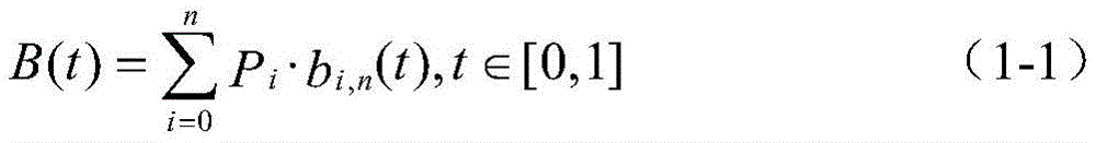
其中bi,n(t)为n阶伯恩斯坦基底多项式,其数学定义为:where b i,n (t) is a Bernstein basis polynomial of order n, which is mathematically defined as:
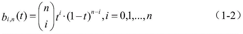
其中,n为Bezier曲线的阶数;t是控制参数,取值范围为[0,1];Pi表示第i+1个控制点。参数t在[0,1]范围内连续变化,则得到n阶Bezier曲线。依次连接控制点Pi,得到的凸多边形称之为控制多边形,其中P0和Pn分别为第一个和最后一个控制点,Bezier曲线必然在控制多边形内部。Among them, n is the order of the Bezier curve; t is the control parameter, the value range is [0, 1]; P i represents the i+1th control point. If the parameter t changes continuously in the range of [0,1], the nth order Bezier curve is obtained. Connecting the control points P i in turn, the obtained convex polygon is called a control polygon, where P 0 and P n are the first and last control points respectively, and the Bezier curve must be inside the control polygon.
根据公式1‐1和1‐2,得到3阶Bezier曲线的x,y坐标分别为:According to formulas 1-1 and 1-2, the x and y coordinates of the third-order Bezier curve are obtained as:
x(t)=x0(1-t)3+3x1t(1-t)2+3x2t2(1-t)+x3t3,t∈[0,1]x(t)=x 0 (1-t) 3 +3x 1 t(1-t) 2 +3x 2 t 2 (1-t)+x 3 t 3 ,t∈[0,1]
y(t)=y0(1-t)3+3y1t(1-t)2+3y2t2(1-t)+y3t3,t∈[0,1]y(t)=y 0 (1-t) 3 +3y 1 t(1-t) 2 +3y 2 t 2 (1-t)+y 3 t 3 ,t∈[0,1]
整理成关于参数的三阶多项式有:Arranged into third-order polynomials about the parameters are:
x(t)=[(x3-x0)+3(x1-x2)]t3+3(x0-2x1+x2)t2+3(x1-x0)t+x0,t∈[0,1]x(t)=[(x 3 -x 0 )+3(x 1 -x 2 )]t 3 +3(x 0 -2x 1 +x 2 )t 2 +3(x 1 -x 0 )t+ x 0 ,t∈[0,1]
y(t)=[(y3-y0)+3(y1-y2)]t3+3(y0-2y1+y2)t2+3(y1-y0)t+y0,t∈[0,1]y(t)=[(y 3 -y 0 )+3(y 1 -y 2 )]t 3 +3(y 0 -2y 1 +y 2 )t 2 +3(y 1 -y 0 )t+ y 0 ,t∈[0,1]
为了表示方便,将公式简化成如下形式:For convenience, the formula is simplified to the following form:
x(t)=a3t3+a2t2+a1t+a0,t∈[0,1] (1-3)x(t)=a 3 t 3 +a 2 t 2 +a 1 t+a 0 ,t∈[0,1] (1-3)
y(t)=b3t3+b2t2+b1t+b0,t∈[0,1] (1-4)y(t)=b 3 t 3 +b 2 t 2 +b 1 t+b 0 , t∈[0,1] (1-4)
式中,a3=(x3-x0)+3(x1-x2),a2=3(x0-2x1+x2),a1=3(x1-x0),a0=x0,b3=(y3-y0)+3(y1-y2),b2=3(y0-2y1+y2),b1=3(y1-y0),b0=y0。In the formula, a 3 =(x 3 -x 0 )+3(x 1 -x 2 ), a 2 =3(x 0 -2x 1 +x 2 ), a 1 =3(x 1 -x 0 ), a 0 =x 0 , b 3 =(y 3 -y 0 )+3(y 1 -y 2 ), b 2 =3(y 0 -2y 1 +y 2 ), b 1 =3(y 1 -y 0 ), b 0 =y 0 .
三阶Bezier曲线的斜率曲线为:
曲率曲线为:
根据图2,已知起始点位姿P0(x0,y0,θ0)和目标点位姿P3(x3,y3,θ3),现确定另外两个控制点P1(x1,y1)和P2(x2,y2)的选取范围:由公式(1-6)可求得起始点P0处的曲率为According to Fig. 2, the starting point pose P 0 (x 0 , y 0 , θ 0 ) and the target point pose P 3 (x 3 , y 3 , θ 3 ) are known, and two other control points P 1 ( Selection range of x 1 , y 1 ) and P 2 (x 2 , y 2 ): From formula (1-6), it can be obtained that the curvature at the starting point P 0 is

目标点P3处的曲率为The curvature at the target point P3 is

随着|P0P1|和|P2P3|的增大,轨迹端点处的曲率半径也会随之增大,所以车辆端点处的最小转弯半径对应着|P0P1|和|P2P3|的下限。即As |P 0 P 1 | and |P 2 P 3 | increase, the radius of curvature at the endpoint of the trajectory also increases, so the minimum turning radius at the vehicle endpoint corresponds to |P 0 P 1 | and | Lower bound for P 2 P 3 |. which is

其中,rmin表示车辆的最小转弯半径。同时,我们依据线段P0P3的长度确定|P0P1|和|P2P3|的上限,即|P0P1|≤|P0P3|及|P2P3|≤|P0P3|。因此我们可以确定控制点的选择有如下约束:Among them, r min represents the minimum turning radius of the vehicle. At the same time, we determine the upper limit of |P 0 P 1 | and |P 2 P 3 | according to the length of the line segment P 0 P 3 , namely |P 0 P 1 |≤|P 0 P 3 | and |P 2 P 3 |≤ | P0P3 | . Therefore, we can determine that the selection of control points has the following constraints:
l1≤|P0P1|≤l3,l2≤|P2P3|≤l3 l 1 ≤|P 0 P 1 |≤l 3 , l 2 ≤|P 2 P 3 |≤l 3
现对|P0P1|和|P2P3|的取值范围三等分,可以得到4个控制点,即P1(x1,y1)和P2(x2,y2)各有4种取值,用公式表示如下:Now, by dividing the value range of |P 0 P 1 | and |P 2 P 3 | into three equal parts, four control points can be obtained, namely P 1 (x 1 , y 1 ) and P 2 (x 2 , y 2 ) There are 4 values for each, and the formula is as follows:
对于P1,有:For P 1 , there are:


对于P2,有:For P 2 , there are:


由于P1和P2各有4种取值,因此有4x4=16种组合的控制点,对应的有16条Bezier曲线。若将|P0P1|和|P2P3|的取值范围n等分,可以得到n+1个控制点,对应的有(n+1)2条Bezier曲线。Since P 1 and P 2 each have 4 values, there are 4x4=16 combinations of control points, corresponding to 16 Bezier curves. If the value ranges of |P 0 P 1 | and |P 2 P 3 | are equally divided into n, n+1 control points can be obtained, corresponding to (n+1) 2 Bezier curves.
得到每组控制点后,可以计算出参数方程(1-3)、(1-4)的系数a0,a1,a2,a3以及b0,b1,b2,b3,从而得到Bezier曲线方程,即无人车辆的轨迹方程。After each set of control points is obtained, the coefficients a 0 , a 1 , a 2 , a 3 and b 0 , b 1 , b 2 , b 3 of the parametric equations (1-3) and (1-4) can be calculated, so that The Bezier curve equation is obtained, that is, the trajectory equation of the unmanned vehicle.
(1c)通过曲率约束对多条Bezier曲线进行筛选;(1c) Screening multiple Bezier curves through curvature constraints;
得到候选轨迹簇之后,需要依据最大曲率约束对轨迹簇进行筛选,因为在某一条轨迹上存在最小转弯半径小于车辆的固有转弯半径(低速下是个定值)的点,那么该轨迹对车辆来讲是不可行的。由于每一条轨迹都是用位置点集表示的,可根据公式After obtaining the candidate trajectory cluster, the trajectory cluster needs to be screened according to the maximum curvature constraint, because there is a point on a certain trajectory whose minimum turning radius is smaller than the vehicle's inherent turning radius (a fixed value at low speed), then the trajectory is for the vehicle. is not feasible. Since each trajectory is represented by a set of position points, it can be calculated according to the formula

计算出每一个点的曲率,从而得到每个点的曲率半径Calculate the curvature of each point to get the radius of curvature of each point
然后判断曲线是否存在某点的曲率半径满足Then judge whether the curve has a point with a radius of curvature that satisfies
r≤rmin r≤rmin
若满足,则该曲线是不可行的,舍弃该曲线;否则,保留该曲线。If it is satisfied, the curve is infeasible, and the curve is discarded; otherwise, the curve is retained.
(1d)通过碰撞检测对多条Bezier曲线再一次进行筛选;(1d) Screening multiple Bezier curves again by collision detection;
通过步骤(1c)筛选后的轨迹,考虑到车辆行进过程中需要避开障碍物,因此还需要对轨迹进一步做碰撞检测,选出无碰的轨迹。Through the trajectories screened in step (1c), considering that the vehicle needs to avoid obstacles during the traveling process, it is necessary to further perform collision detection on the trajectories, and select a collision-free trajectory.
(1e)若经过(1c)、(1d)步骤筛选后已无剩下Bezier曲线,则认为Bezier曲线规划路口可行轨迹失败,转用VFH与Bezier曲线相结合的方法;否则,通过轨迹最平滑准则在剩余的曲线里筛选出最优的轨迹。(1e) If there is no remaining Bezier curve after the screening of steps (1c) and (1d), it is considered that the Bezier curve fails to plan the feasible trajectory of the intersection, and the method combining VFH and Bezier curve is used; otherwise, the smoothest trajectory criterion is adopted. The optimal trajectory is filtered out of the remaining curves.
若步骤(1d)筛选后还有满足要求的曲线,那么我们需要选择一条最优的曲线做为车辆最终的轨迹;现我们以轨迹最平滑为准则,选出最优轨迹。If there are still curves that meet the requirements after screening in step (1d), then we need to select an optimal curve as the final trajectory of the vehicle; now we select the optimal trajectory based on the smoothest trajectory.
首先,根据公式First, according to the formula

计算出每一个点的曲率κ,然后根据公式Calculate the curvature κ of each point, and then according to the formula

可以得到曲率平方和最小的那条曲线,该曲线就是最平滑的曲线,同时也是满足曲率要求,无碰的可行轨迹。The curve with the smallest sum of squares of curvature can be obtained, which is the smoothest curve, and is also a feasible trajectory that meets the curvature requirements and is collision-free.
2)若Bezier曲线簇都不满足以上约束,导致不存在期望的轨迹,则用VFH算法与Bezier曲线相结合的算法规划轨迹,具体步骤如下:2) If the Bezier curve cluster does not satisfy the above constraints, resulting in no desired trajectory, use the algorithm combining the VFH algorithm and the Bezier curve to plan the trajectory. The specific steps are as follows:
(2a)根据车辆运动学模型确定车辆的活动区域;(2a) Determine the active area of the vehicle according to the vehicle kinematics model;
由图3可知,根据车辆的最小转弯半径rmin以及搜索步长s,可以得到活动区域在车体当前位姿下的极坐标表示:As can be seen from Figure 3, according to the minimum turning radius r min of the vehicle and the search step size s, the polar coordinate representation of the active area under the current pose of the vehicle body can be obtained:

P表示以车辆后轴中心为坐标原点,航向角方向为零度的极坐标系;P represents a polar coordinate system with the center of the rear axle of the vehicle as the coordinate origin and the heading angle direction of zero degrees;
ρ表示活动区域的距离范围,并且有ρ∈[0,ρmax],ρmax表示最大活动距离;ρ represents the distance range of the active area, and there is ρ∈ [0,ρmax], ρmax represents the maximum activity distance;


则搜索到的轨迹点必然在弧线
(2b)从传感器获取障碍物信息建立栅格图;(2b) Obtaining obstacle information from sensors to build a grid map;
由于VFH算法是用栅格图来表征环境的,因此获取障碍物信息后需要以栅格图的形式表现出来。Since the VFH algorithm uses a grid map to represent the environment, it needs to be displayed in the form of a grid map after obtaining the obstacle information.
障碍物可以看成是一个box,因此从传感器处收到的是该box的四个角点坐标,现需要根据这4个坐标点将障碍物映射到栅格图坐标系中。The obstacle can be regarded as a box, so the coordinates of the four corner points of the box are received from the sensor, and now the obstacle needs to be mapped to the grid map coordinate system according to these four coordinate points.
如图4所示,以车体的朝向为X轴正方向,车的后轴中心点为坐标系原点建立右手坐标系做为栅格图坐标系。假设该栅格图的尺寸是GridM*GridN,即有GridM行,GridN列;且分辨率是Ratio,即每个栅格的长宽都是Ratio;4个角点坐标分别是(x1,y1)、(x2,y2)、(x3,y3)、(x4,y4)。首先获得包围box的虚线框,步骤如下:令As shown in Figure 4, the orientation of the vehicle body is the positive direction of the X-axis, and the center point of the rear axle of the vehicle is the origin of the coordinate system to establish a right-hand coordinate system as the grid coordinate system. Suppose the size of the grid image is GridM*GridN, that is, there are GridM rows and GridN columns; and the resolution is Ratio, that is, the length and width of each grid are Ratio; the coordinates of the four corner points are (x 1 , y 1 ), (x 2 , y 2 ), (x 3 , y 3 ), (x 4 , y 4 ). First get the dashed box surrounding the box, the steps are as follows:
xmin=min{x1,x2,x3,x4},xmax={x1,x2,x3,x4}x min =min{x 1 ,x 2 ,x 3 ,x 4 }, x max ={x 1 ,x 2 ,x 3 ,x 4 }
ymin=min{y1,y2,y3,y4},ymax=max{y1,y2,y3,y4}y min =min{y 1 ,y 2 ,y 3 ,y 4 }, y max =max{y 1 ,y 2 ,y 3 ,y 4 }
可以通过如下公式can be obtained by the following formula


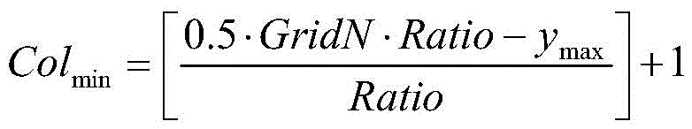

计算出虚线框在栅格图上的位置。其中,Rowmin表示虚线框所占据的行的最小值,Rowmax表示所占据的行的最大值;Colmin表示虚线框所占据的列的最小值,Colmax表示所占据的列的最大值。[]符号表示向下取整,比如[1.5]=1。Calculates the position of the dotted box on the grid. Among them, Row min represents the minimum value of the row occupied by the dashed box, Row max represents the maximum value of the row occupied; Col min represents the minimum value of the column occupied by the dashed box, and Col max represents the maximum value of the column occupied. The [ ] symbol indicates rounding down, such as [1.5]=1.
计算出Rowmin、Rowmax、Colmin、Colmax后,我们就知道了虚线框所包含的每一个栅格的位置。接下来要做的是判断虚线框里的每一个栅格是否落在box内,具体方法是判断每一个栅格的四个角点是否存在一个或多个点落入到box内;若存在,则认为该栅格是被障碍物占据的,相应的值用1表示;若不存在,则该栅格未被障碍物占据,相应的值用0表示。After calculating Row min , Row max , Col min , and Col max , we know the position of each grid contained in the dotted box. The next thing to do is to determine whether each grid in the dotted box falls within the box. The specific method is to determine whether one or more points of the four corners of each grid fall into the box; if so, The grid is considered to be occupied by obstacles, and the corresponding value is represented by 1; if it does not exist, the grid is not occupied by obstacles, and the corresponding value is represented by 0.
现介绍如何判断一个点是否落入到凸四边形内。假设该凸四边形为ABCD,且ABCD为顺时针,待判断的点为M,则需要满足:Now we will introduce how to judge whether a point falls within a convex quadrilateral. Assuming that the convex quadrilateral is ABCD, and ABCD is clockwise, and the point to be judged is M, it needs to satisfy:
ABxAM>0,BCxBM>0,CDxCM>0,DAxDM>0ABxAM>0,BCxBM>0,CDxCM>0,DAxDM>0
即可证明点M在凸四边形内部。It can be proved that the point M is inside the convex quadrilateral.
计算出每个栅格对应的0‐1值,相当于建立起了栅格图。The 0-1 value corresponding to each grid is calculated, which is equivalent to establishing a grid map.
(2c)将活动区域分成多个扇区,并判断每个扇区是否有障碍物占据;(2c) Divide the active area into multiple sectors, and determine whether each sector is occupied by obstacles;
假设活动区域的角度为ω,将活动区域分成k个扇区,如图5所示,则每个扇区的角度为w/k。Assuming that the angle of the active area is ω, the active area is divided into k sectors, as shown in Figure 5, the angle of each sector is w/k.
现判断每个被障碍物占据的栅格是否在某个扇区内,具体步骤为:将每个栅格抽象成质点,可以是每个栅格的中心点,假设该栅格处于第Row行,第Col列,则该栅格的坐标点(x,y)为:Now judge whether each grid occupied by obstacles is in a certain sector, the specific steps are: abstract each grid into a mass point, which can be the center point of each grid, assuming that the grid is in the row of Row , column Col, then the coordinate point (x, y) of the grid is:


从而可以计算出该栅格与车体的距离,若该距离小于搜索步长s,则用角度继续判断是否在扇区内:计算该栅格坐标点与车体坐标点连线所形成的与X轴的夹角,假设为θ,若

计算出具体位于哪个扇区(n表示第n个扇区,n=0,1,2,.....,k)。最后对每个扇区的被障碍物占据的栅格个数做统计,若某个扇区的该数值大于0,则认为有障碍物占据,是不可行的;否则认为是可行的扇区。Calculate which sector it is located in (n represents the nth sector, n=0, 1, 2, ....., k). Finally, count the number of grids occupied by obstacles in each sector. If the value of a certain sector is greater than 0, it is considered to be occupied by obstacles, which is infeasible; otherwise, it is considered a feasible sector.
(2d)考虑车宽对可行扇区进行筛选;(2d) Screen the feasible sectors considering the vehicle width;
一般每个扇区对应的弧长只有0.42m左右,而车宽有2m,这意味着若车选择了该扇区,虽然该扇区没有障碍物,但邻近扇区有障碍物依旧有可能产生碰撞,因此选择扇区时应考虑车宽。根据计算可知,5个扇区对应的弧长大于2m,又由于车体的对称性,选择的可行扇区需满足其左边相邻的两个扇区与右边相邻的两个扇区也是可行的。Generally, the arc length corresponding to each sector is only about 0.42m, and the width of the vehicle is 2m, which means that if the vehicle selects this sector, although there are no obstacles in the sector, there may still be obstacles in the adjacent sectors. collision, so car width should be considered when selecting sectors. According to the calculation, the arc length corresponding to the five sectors is greater than 2m, and due to the symmetry of the vehicle body, the selected feasible sector must satisfy the two adjacent sectors on the left and the two adjacent sectors on the right. of.
(2e)用Bezier曲线做为参考曲线选择最优扇区;(2e) Use the Bezier curve as the reference curve to select the optimal sector;
经过(2d)步骤后,选出的满足上述条件的扇区可能有多个,因此我们选择用Bezier曲线做为参考曲线选择最优扇区。首先根据起始点和目标点的位姿以及轨迹最平滑准则选出一条最平滑的Bezier曲线做为参考曲线,如图6所示,具体过程可参照(1)中的步骤;由于每个扇区都对应一个轨迹点,对于每一个满足(2d)条件的扇区,都可以通过其对应的轨迹点算出该点距离Bezier曲线的最短距离(由于Bezier曲线是用点集表示,计算最短距离时可先计算轨迹点距离曲线上每一个点的距离,然后在这些距离里取最短距离)。假设Bezier曲线由n个点表示,满足(2d)条件的扇区有m个,对于每一个扇区,可以计算出该扇区对于参考线的最短距离After step (2d), there may be multiple selected sectors that meet the above conditions, so we choose to use the Bezier curve as the reference curve to select the optimal sector. First, select the smoothest Bezier curve as the reference curve according to the pose of the starting point and the target point and the smoothest trajectory criterion, as shown in Figure 6, the specific process can refer to the steps in (1); All correspond to a trajectory point. For each sector that satisfies the (2d) condition, the shortest distance from the point to the Bezier curve can be calculated through its corresponding trajectory point (because the Bezier curve is represented by a set of points, when calculating the shortest distance can be First calculate the distance between the track point and each point on the curve, and then take the shortest distance among these distances). Assuming that the Bezier curve is represented by n points, there are m sectors that satisfy the condition (2d), and for each sector, the shortest distance of the sector to the reference line can be calculated
di,min=min{di,1,di,2,....,di,n},i=1,2,...,md i,min =min{d i,1 ,d i,2 ,....,d i,n },i=1,2,...,m
其中,i表示第i个满足(2d)条件的扇区,di,n表示第i个扇区对参考线上第n个点的距离,di,min表示第i个扇区距离参考线的最短距离。最后,我们可以通过公式Among them, i represents the ith sector that satisfies the condition of (2d), d i,n represents the distance from the ith sector to the nth point on the reference line, and d i, min represents the distance from the ith sector to the reference line the shortest distance. Finally, we can pass the formula
k=argmin(di,min),k=1,2,3,...,mk=argmin(d i,min ),k=1,2,3,...,m
计算出哪个扇区是距离参考线最短,并认为该扇区是最优扇区,该扇区对应的轨迹点是最优轨迹点。Calculate which sector is the shortest from the reference line, and consider this sector to be the optimal sector, and the trajectory point corresponding to the sector is the optimal trajectory point.
(2f)离散位置点集做控制点生成B样条曲线;(2f) The discrete position point set is used as the control point to generate a B-spline curve;
由(2e)步骤得到的轨迹点属于位置点集,无朝向角、速度等信息,而且点比较稀疏,无法做为车辆的可行轨迹。这里依据位置点集生成B样条曲线的方式生成可行驶路径。根据上述的B样条数学模型,取n=3,k=3带入公式(2-1)和(2-2)中得到三阶B样条曲线的基函数为:The trajectory points obtained by step (2e) belong to the position point set, without information such as orientation angle and speed, and the points are relatively sparse, so they cannot be used as the feasible trajectory of the vehicle. Here, the drivable path is generated according to the method of generating the B-spline curve from the position point set. According to the above-mentioned B-spline mathematical model, take n=3, k=3 and bring it into formulas (2-1) and (2-2) to obtain the basis function of the third-order B-spline curve:

现将位置点集做为B样条曲线的控制点即可得到最终轨迹,该轨迹含有位置信息,航向角信息和曲率信息,可以做为无人驾驶车辆的可行路径。Now take the position point set as the control point of the B-spline curve to get the final trajectory, which contains the position information, heading angle information and curvature information, and can be used as the feasible path of the unmanned vehicle.
我们分别验证了路口存在单障碍物以及多障碍物时该路径规划算法的有效性。实验结果显示,无人车在遇到障碍物时能够有效避障并保持安全距离,绕过障碍物后在Bezier曲线的约束下能够按照期望的目标位姿回到目标点上,该算法实时有效。We respectively verify the effectiveness of the path planning algorithm when there are single obstacles and multiple obstacles at the intersection. The experimental results show that the unmanned vehicle can effectively avoid obstacles and maintain a safe distance when encountering obstacles. After bypassing the obstacles, it can return to the target point according to the desired target pose under the constraints of the Bezier curve. The algorithm is effective in real time. .
Claims (4)


Priority Applications (1)
| Application Number | Priority Date | Filing Date | Title |
|---|---|---|---|
| CN201710214224.6A CN107168305B (en) | 2017-04-01 | 2017-04-01 | Bezier and VFH-based unmanned vehicle track planning method under intersection scene |
Applications Claiming Priority (1)
| Application Number | Priority Date | Filing Date | Title |
|---|---|---|---|
| CN201710214224.6A CN107168305B (en) | 2017-04-01 | 2017-04-01 | Bezier and VFH-based unmanned vehicle track planning method under intersection scene |
Publications (2)
| Publication Number | Publication Date |
|---|---|
| CN107168305A CN107168305A (en) | 2017-09-15 |
| CN107168305B true CN107168305B (en) | 2020-03-17 |
Family
ID=59849636
Family Applications (1)
| Application Number | Title | Priority Date | Filing Date |
|---|---|---|---|
| CN201710214224.6A Expired - Fee Related CN107168305B (en) | 2017-04-01 | 2017-04-01 | Bezier and VFH-based unmanned vehicle track planning method under intersection scene |
Country Status (1)
| Country | Link |
|---|---|
| CN (1) | CN107168305B (en) |
Families Citing this family (44)
| Publication number | Priority date | Publication date | Assignee | Title |
|---|---|---|---|---|
| CN107963077B (en) * | 2017-10-26 | 2020-02-21 | 东软集团股份有限公司 | Control method, device and system for vehicle passing through intersection |
| US11073828B2 (en) * | 2017-12-08 | 2021-07-27 | Samsung Electronics Co., Ltd. | Compression of semantic information for task and motion planning |
| CN108121347B (en) * | 2017-12-29 | 2020-04-07 | 北京三快在线科技有限公司 | Method and device for controlling movement of equipment and electronic equipment |
| JP7091670B2 (en) * | 2018-01-18 | 2022-06-28 | 株式会社デンソー | Travel track data generation device in an intersection, travel track data generation program in an intersection, and storage medium |
| CN108549385B (en) * | 2018-05-22 | 2021-05-04 | 东南大学 | Robot dynamic path planning method combining A-x algorithm and VFH obstacle avoidance algorithm |
| CN110657814A (en) * | 2018-06-29 | 2020-01-07 | 比亚迪股份有限公司 | Trajectory planning method and device, vehicle and control method and system thereof |
| CN110730934A (en) * | 2018-08-01 | 2020-01-24 | 深圳市大疆创新科技有限公司 | Method and device for switching track |
| CN109557912B (en) * | 2018-10-11 | 2020-07-28 | 同济大学 | A decision-making planning method for autonomous driving special operation vehicles |
| US10969789B2 (en) * | 2018-11-09 | 2021-04-06 | Waymo Llc | Verifying predicted trajectories using a grid-based approach |
| CN109434831B (en) * | 2018-11-12 | 2020-11-27 | 深圳前海达闼云端智能科技有限公司 | Robot operating method, device, robot, electronic device and readable medium |
| CN109668569A (en) * | 2018-12-08 | 2019-04-23 | 华东交通大学 | Path rapid generation in a kind of intelligent driving |
| CN109471441B (en) * | 2018-12-11 | 2022-02-01 | 湖南三一智能控制设备有限公司 | Pavement mechanical equipment, online planning method and system thereof and readable storage medium |
| CN109375632B (en) * | 2018-12-17 | 2020-03-20 | 清华大学 | Real-time trajectory planning method for automatic driving vehicle |
| CN109656250A (en) * | 2018-12-26 | 2019-04-19 | 芜湖哈特机器人产业技术研究院有限公司 | A kind of path following method of laser fork truck |
| EP3692339B1 (en) * | 2018-12-26 | 2022-02-09 | Baidu.com Times Technology (Beijing) Co., Ltd. | Polynomial-fit based reference line smoothing method for high speed planning of autonomous driving vehicles |
| CN109885891B (en) * | 2019-01-24 | 2022-09-30 | 中国科学院合肥物质科学研究院 | Intelligent vehicle GPU parallel acceleration trajectory planning method |
| CN109947112B (en) * | 2019-04-04 | 2020-07-21 | 大连理工大学 | Optimal time trajectory planning method for two-wheeled self-balancing vehicle in linear fixed-point motion |
| CN110221601A (en) * | 2019-04-30 | 2019-09-10 | 南京航空航天大学 | A kind of more AGV system dynamic barrier Real-time Obstacle Avoidance Methods and obstacle avoidance system |
| CN110427046B (en) * | 2019-07-26 | 2022-09-30 | 沈阳航空航天大学 | Three-dimensional smooth random-walking unmanned aerial vehicle cluster moving model |
| CN110440806A (en) * | 2019-08-12 | 2019-11-12 | 苏州寻迹智行机器人技术有限公司 | A kind of AGV accurate positioning method that laser is merged with two dimensional code |
| CN110502010B (en) * | 2019-08-15 | 2021-06-04 | 同济大学 | A mobile robot indoor autonomous navigation control method based on Bezier curve |
| CN110553660B (en) * | 2019-08-31 | 2023-03-24 | 武汉理工大学 | Unmanned vehicle trajectory planning method based on A-star algorithm and artificial potential field |
| CN110865642A (en) * | 2019-11-06 | 2020-03-06 | 天津大学 | A Path Planning Method Based on Mobile Robot |
| CN110908373B (en) * | 2019-11-11 | 2021-05-07 | 南京航空航天大学 | An Intelligent Vehicle Trajectory Planning Method Based on Improved Artificial Potential Field |
| CN111189453A (en) * | 2020-01-07 | 2020-05-22 | 深圳南方德尔汽车电子有限公司 | Bezier-based global path planning method and device, computer equipment and storage medium |
| CN111523719B (en) * | 2020-04-16 | 2024-03-15 | 东南大学 | A hybrid path planning method based on kinematic constraints of articulated vehicles |
| CN111599179B (en) * | 2020-05-21 | 2021-09-03 | 北京航空航天大学 | No-signal intersection vehicle motion planning method based on risk dynamic balance |
| CN111750859B (en) * | 2020-05-29 | 2021-11-05 | 广州极飞科技股份有限公司 | Transition path planning method and related device |
| CN111707269B (en) * | 2020-06-23 | 2022-04-05 | 东南大学 | A method of UAV path planning in 3D environment |
| CN112269965B (en) * | 2020-08-10 | 2024-04-05 | 中国北方车辆研究所 | Continuous curvature path optimization method under incomplete constraint condition |
| CN112129291B (en) * | 2020-08-26 | 2022-04-01 | 南京航空航天大学 | Bezier curve-based fixed-wing unmanned aerial vehicle track optimization method |
| CN112099493B (en) * | 2020-08-31 | 2021-11-19 | 西安交通大学 | Autonomous mobile robot trajectory planning method, system and equipment |
| CN112132869B (en) * | 2020-11-02 | 2024-07-19 | 中远海运科技股份有限公司 | Vehicle target track tracking method and device |
| CN113495562B (en) * | 2021-06-07 | 2024-03-29 | 深圳市塞防科技有限公司 | Simulation path generation method, device, equipment and computer storage medium |
| CN113442140B (en) * | 2021-06-30 | 2022-05-24 | 同济人工智能研究院(苏州)有限公司 | Cartesian space obstacle avoidance planning method based on Bezier optimization |
| CN113467498B (en) * | 2021-07-14 | 2022-07-01 | 西北工业大学 | A Bezier-convex optimization-based trajectory planning method for the ascent segment of a launch vehicle |
| CN115705054B (en) * | 2021-08-11 | 2025-12-19 | 灵动科技(安徽)有限公司 | Path planning method for mobile robot and program product |
| CN116457853A (en) * | 2021-10-25 | 2023-07-18 | 华为技术有限公司 | Vehicle track planning method and device and vehicle |
| CN114184206B (en) * | 2021-12-03 | 2024-04-19 | 北京车慧达科技有限公司 | Method and device for generating driving route based on vehicle track points |
| CN116414116A (en) * | 2021-12-29 | 2023-07-11 | 灵动科技(北京)有限公司 | Path planning method, motion control method and computer program product |
| CN114038203A (en) * | 2022-01-12 | 2022-02-11 | 成都四方伟业软件股份有限公司 | Curve fitting method and device for two-point intersection lane in traffic simulation |
| CN114815853B (en) * | 2022-06-21 | 2024-05-31 | 清华大学 | A path planning method and system considering road obstacle characteristics |
| CN115520218B (en) * | 2022-09-27 | 2023-05-23 | 李晓赫 | Four-point turning track planning method for automatic driving vehicle |
| CN117533354B (en) * | 2023-12-28 | 2024-04-02 | 安徽蔚来智驾科技有限公司 | Trajectory generation method, driving control method, storage medium and intelligent device |
Citations (5)
| Publication number | Priority date | Publication date | Assignee | Title |
|---|---|---|---|---|
| KR20120098152A (en) * | 2011-02-28 | 2012-09-05 | 한국과학기술연구원 | Path planning system for mobile robot |
| CN104133473A (en) * | 2008-10-24 | 2014-11-05 | 格瑞股份公司 | Control method of autonomously driven vehicle |
| CN106313047A (en) * | 2016-09-28 | 2017-01-11 | 华中科技大学 | Robot real-time corner transition method based on Bezier spline |
| CN106382944A (en) * | 2016-10-08 | 2017-02-08 | 浙江国自机器人技术有限公司 | Route planning method of mobile robot |
| CN106647754A (en) * | 2016-12-20 | 2017-05-10 | 安徽农业大学 | Path planning method for orchard tracked robot |
-
2017
- 2017-04-01 CN CN201710214224.6A patent/CN107168305B/en not_active Expired - Fee Related
Patent Citations (5)
| Publication number | Priority date | Publication date | Assignee | Title |
|---|---|---|---|---|
| CN104133473A (en) * | 2008-10-24 | 2014-11-05 | 格瑞股份公司 | Control method of autonomously driven vehicle |
| KR20120098152A (en) * | 2011-02-28 | 2012-09-05 | 한국과학기술연구원 | Path planning system for mobile robot |
| CN106313047A (en) * | 2016-09-28 | 2017-01-11 | 华中科技大学 | Robot real-time corner transition method based on Bezier spline |
| CN106382944A (en) * | 2016-10-08 | 2017-02-08 | 浙江国自机器人技术有限公司 | Route planning method of mobile robot |
| CN106647754A (en) * | 2016-12-20 | 2017-05-10 | 安徽农业大学 | Path planning method for orchard tracked robot |
Non-Patent Citations (1)
| Title |
|---|
| 无人驾驶车实时地图构建与自主运动规划;姜楠 等;《第三十一届中国控制会议论文集C卷》;20120727;第4930-4935页 * |
Also Published As
| Publication number | Publication date |
|---|---|
| CN107168305A (en) | 2017-09-15 |
Similar Documents
| Publication | Publication Date | Title |
|---|---|---|
| CN107168305B (en) | Bezier and VFH-based unmanned vehicle track planning method under intersection scene | |
| Souissi et al. | Path planning: A 2013 survey | |
| CN111324848B (en) | Optimization method of vehicle trajectory data of mobile lidar measurement system | |
| CN107085437A (en) | A UAV trajectory planning method based on EB‑RRT | |
| CN113495566B (en) | Curvature constraint fusion potential field method-based D × Lite unmanned vehicle local path planning method | |
| KR101339480B1 (en) | Trajectory planning method for mobile robot using dual tree structure based on rrt | |
| CN110320933A (en) | Unmanned plane avoidance motion planning method under a kind of cruise task | |
| CN112539750B (en) | Intelligent transportation vehicle path planning method | |
| CN114610066A (en) | Formation flight trajectory generation method of distributed swarm UAV in complex and unknown environment | |
| CN110032182B (en) | Visual graph method and stable sparse random fast tree robot planning algorithm are fused | |
| WO2018176596A1 (en) | Unmanned bicycle path planning method based on weight-improved particle swarm optimization algorithm | |
| CN112965485A (en) | Robot full-coverage path planning method based on secondary region division | |
| Fuji et al. | Trajectory planning for automated parking using multi-resolution state roadmap considering non-holonomic constraints | |
| CN116331264A (en) | A Robust Planning Method and System for Obstacle Avoidance Paths with Unknown Obstacle Distribution | |
| Wen et al. | G²vd planner: Efficient motion planning with grid-based generalized voronoi diagrams | |
| CN114428499A (en) | Astar and DWA algorithm fused mobile trolley path planning method | |
| CN115826586A (en) | Path planning method and system fusing global algorithm and local algorithm | |
| CN118778650A (en) | Improved A-star algorithm for mobile robot motion planning | |
| Han et al. | An enhanced adaptive 3D path planning algorithm for mobile robots with obstacle buffering and improved Theta* using minimum snap trajectory smoothing | |
| CN117367446A (en) | Unmanned vehicle path planning method and system based on improved A*-TEB fusion algorithm | |
| CN120506970A (en) | Outdoor robot path planning method based on improved bidirectional A and DWA algorithm | |
| Dang | Autonomous mobile robot path planning based on enhanced A* algorithm integrating with time elastic band | |
| Wu et al. | Real-time three-dimensional smooth path planning for unmanned aerial vehicles in completely unknown cluttered environments | |
| Zhu et al. | Obstacle-avoidance path planning of unmanned vehicles based on polynomial optimization | |
| Wang et al. | Research on path planning of mobile robot based on improved jump point search algorithm |
Legal Events
| Date | Code | Title | Description |
|---|---|---|---|
| PB01 | Publication | ||
| PB01 | Publication | ||
| SE01 | Entry into force of request for substantive examination | ||
| SE01 | Entry into force of request for substantive examination | ||
| GR01 | Patent grant | ||
| GR01 | Patent grant | ||
| CF01 | Termination of patent right due to non-payment of annual fee | ||
| CF01 | Termination of patent right due to non-payment of annual fee |
Granted publication date: 20200317 |