CN107104011B - Rotation control system for equipment - Google Patents
Rotation control system for equipment Download PDFInfo
- Publication number
- CN107104011B CN107104011B CN201710068858.5A CN201710068858A CN107104011B CN 107104011 B CN107104011 B CN 107104011B CN 201710068858 A CN201710068858 A CN 201710068858A CN 107104011 B CN107104011 B CN 107104011B
- Authority
- CN
- China
- Prior art keywords
- locking plate
- rotary control
- control member
- pin
- control system
- Prior art date
- Legal status (The legal status is an assumption and is not a legal conclusion. Google has not performed a legal analysis and makes no representation as to the accuracy of the status listed.)
- Active
Links
Images


Classifications
-
- H—ELECTRICITY
- H01—ELECTRIC ELEMENTS
- H01H—ELECTRIC SWITCHES; RELAYS; SELECTORS; EMERGENCY PROTECTIVE DEVICES
- H01H9/00—Details of switching devices, not covered by groups H01H1/00 - H01H7/00
- H01H9/20—Interlocking, locking, or latching mechanisms
- H01H9/28—Interlocking, locking, or latching mechanisms for locking switch parts by a key or equivalent removable member
- H01H9/281—Interlocking, locking, or latching mechanisms for locking switch parts by a key or equivalent removable member making use of a padlock
- H01H9/282—Interlocking, locking, or latching mechanisms for locking switch parts by a key or equivalent removable member making use of a padlock and a separate part mounted or mountable on the switch assembly and movable between an unlocking position and a locking position where it can be secured by the padlock
-
- H—ELECTRICITY
- H01—ELECTRIC ELEMENTS
- H01H—ELECTRIC SWITCHES; RELAYS; SELECTORS; EMERGENCY PROTECTIVE DEVICES
- H01H9/00—Details of switching devices, not covered by groups H01H1/00 - H01H7/00
- H01H9/20—Interlocking, locking, or latching mechanisms
- H01H9/28—Interlocking, locking, or latching mechanisms for locking switch parts by a key or equivalent removable member
- H01H9/281—Interlocking, locking, or latching mechanisms for locking switch parts by a key or equivalent removable member making use of a padlock
-
- G—PHYSICS
- G05—CONTROLLING; REGULATING
- G05G—CONTROL DEVICES OR SYSTEMS INSOFAR AS CHARACTERISED BY MECHANICAL FEATURES ONLY
- G05G1/00—Controlling members, e.g. knobs or handles; Assemblies or arrangements thereof; Indicating position of controlling members
- G05G1/08—Controlling members for hand actuation by rotary movement, e.g. hand wheels
- G05G1/10—Details, e.g. of discs, knobs, wheels or handles
-
- G—PHYSICS
- G05—CONTROLLING; REGULATING
- G05G—CONTROL DEVICES OR SYSTEMS INSOFAR AS CHARACTERISED BY MECHANICAL FEATURES ONLY
- G05G5/00—Means for preventing, limiting or returning the movements of parts of a control mechanism, e.g. locking controlling member
- G05G5/28—Means for preventing, limiting or returning the movements of parts of a control mechanism, e.g. locking controlling member for preventing unauthorised access to the controlling member or its movement to a command position
-
- H—ELECTRICITY
- H01—ELECTRIC ELEMENTS
- H01H—ELECTRIC SWITCHES; RELAYS; SELECTORS; EMERGENCY PROTECTIVE DEVICES
- H01H19/00—Switches operated by an operating part which is rotatable about a longitudinal axis thereof and which is acted upon directly by a solid body external to the switch, e.g. by a hand
- H01H19/02—Details
- H01H19/10—Movable parts; Contacts mounted thereon
- H01H19/14—Operating parts, e.g. turn knob
-
- H—ELECTRICITY
- H01—ELECTRIC ELEMENTS
- H01H—ELECTRIC SWITCHES; RELAYS; SELECTORS; EMERGENCY PROTECTIVE DEVICES
- H01H19/00—Switches operated by an operating part which is rotatable about a longitudinal axis thereof and which is acted upon directly by a solid body external to the switch, e.g. by a hand
- H01H19/36—Switches operated by an operating part which is rotatable about a longitudinal axis thereof and which is acted upon directly by a solid body external to the switch, e.g. by a hand the operating part having only two operative positions, e.g. relatively displaced by 180 degrees
-
- H—ELECTRICITY
- H01—ELECTRIC ELEMENTS
- H01H—ELECTRIC SWITCHES; RELAYS; SELECTORS; EMERGENCY PROTECTIVE DEVICES
- H01H71/00—Details of the protective switches or relays covered by groups H01H73/00 - H01H83/00
- H01H71/10—Operating or release mechanisms
- H01H71/50—Manual reset mechanisms which may be also used for manual release
- H01H71/56—Manual reset mechanisms which may be also used for manual release actuated by rotatable knob or wheel
-
- G—PHYSICS
- G05—CONTROLLING; REGULATING
- G05G—CONTROL DEVICES OR SYSTEMS INSOFAR AS CHARACTERISED BY MECHANICAL FEATURES ONLY
- G05G2505/00—Means for preventing, limiting or returning the movements of parts of a control mechanism, e.g. locking controlling member
-
- H—ELECTRICITY
- H01—ELECTRIC ELEMENTS
- H01H—ELECTRIC SWITCHES; RELAYS; SELECTORS; EMERGENCY PROTECTIVE DEVICES
- H01H71/00—Details of the protective switches or relays covered by groups H01H73/00 - H01H83/00
- H01H71/10—Operating or release mechanisms
- H01H71/50—Manual reset mechanisms which may be also used for manual release
- H01H71/56—Manual reset mechanisms which may be also used for manual release actuated by rotatable knob or wheel
- H01H2071/565—Manual reset mechanisms which may be also used for manual release actuated by rotatable knob or wheel using a add on unit, e.g. a separate rotary actuator unit, mounted on lever actuated circuit breakers
-
- H—ELECTRICITY
- H01—ELECTRIC ELEMENTS
- H01H—ELECTRIC SWITCHES; RELAYS; SELECTORS; EMERGENCY PROTECTIVE DEVICES
- H01H2235/00—Springs
- H01H2235/01—Spiral spring
-
- H—ELECTRICITY
- H01—ELECTRIC ELEMENTS
- H01H—ELECTRIC SWITCHES; RELAYS; SELECTORS; EMERGENCY PROTECTIVE DEVICES
- H01H3/00—Mechanisms for operating contacts
- H01H3/02—Operating parts, i.e. for operating driving mechanism by a mechanical force external to the switch
- H01H3/08—Turn knobs
-
- H—ELECTRICITY
- H01—ELECTRIC ELEMENTS
- H01H—ELECTRIC SWITCHES; RELAYS; SELECTORS; EMERGENCY PROTECTIVE DEVICES
- H01H3/00—Mechanisms for operating contacts
- H01H3/02—Operating parts, i.e. for operating driving mechanism by a mechanical force external to the switch
- H01H3/20—Operating parts, i.e. for operating driving mechanism by a mechanical force external to the switch wherein an auxiliary movement thereof, or of an attachment thereto, is necessary before the main movement is possible or effective, e.g. for unlatching, for coupling
Landscapes
- Engineering & Computer Science (AREA)
- Physics & Mathematics (AREA)
- General Physics & Mathematics (AREA)
- Automation & Control Theory (AREA)
- Computer Security & Cryptography (AREA)
- Switch Cases, Indication, And Locking (AREA)
- Microelectronics & Electronic Packaging (AREA)
- Casings For Electric Apparatus (AREA)
- Lock And Its Accessories (AREA)
Abstract
本发明涉及一种用于设备的旋转控制系统,该系统包括:旋转控制构件;旋转控制手柄;阻挡装置,当旋转构件处于其第一位置时,该阻挡装置能够在阻挡构型与释放构型之间选择性地位移。该系统还包括锁定板,当旋转构件处于其第一位置时,锁定板相对于旋转构件绕第一轴线在锁定位置与解锁位置之间旋转地可移动面。该锁定板配置成,当阻挡装置在其相应的锁定位置与解锁位置之间移位时,将所述阻挡装置在其阻挡和释放构型之间切换。
The present invention relates to a rotation control system for an apparatus, the system comprising: a rotation control member; a rotation control handle; blocking means capable of being in a blocking configuration and a releasing configuration when the rotation member is in its first position Selectively shift between. The system also includes a locking plate that is rotationally movable relative to the rotating member about the first axis between a locked position and an unlocked position when the rotating member is in its first position. The locking plate is configured to switch the blocking device between its blocking and releasing configurations when the blocking device is displaced between its respective locked and unlocked positions.
Description
技术领域technical field
本发明涉及一种用于设备的旋转控制系统。本发明还涉及包括可控电气设备和用于控制该电气设备的旋转控制系统的电气外壳。The present invention relates to a rotation control system for equipment. The invention also relates to an electrical enclosure comprising a controllable electrical device and a rotation control system for controlling the electrical device.
背景技术Background technique
本发明更特别地应用到用于诸如断路器的电气设备的旋转控制系统。众所周知,这种系统包括旋转控制构件,该旋转控制构件可以在与电气设备的不同电气状态相关联的预定位置之间旋转移位,例如打开和关闭状态。对于断路器,例如,这些电气状态对应于闭合状态和断开状态。通常,电气设备被在该电气外壳的后壁上放置在电气外壳内。旋转控制手柄放置在外壳的门上,面向后壁,以便能够被使用者从外壳的外部接近和启动。该手柄例如通过刚性轴连接到旋转构件,用于旋转控制手柄,以驱动旋转构件在其预定位置之间旋转,从而控制电气设备。The present invention applies more particularly to rotational control systems for electrical equipment such as circuit breakers. Such systems are known to include a rotary control member that is rotationally displaceable between predetermined positions associated with different electrical states of the electrical device, such as open and closed states. For circuit breakers, for example, these electrical states correspond to closed and open states. Typically, electrical equipment is placed within an electrical enclosure on the rear wall of the electrical enclosure. The rotary control handle is placed on the door of the enclosure, facing the rear wall, so as to be accessible and activated by the user from outside the enclosure. The handle is connected to the rotating member, eg by a rigid shaft, for rotating the control handle to drive the rotating member to rotate between its predetermined positions to control the electrical device.
出于安全原因,期望的是,当外壳的门打开时,旋转构件能够被锁定在预定位置,通常是其对应于电气设备的打开或关闭状态的位置。这在电气设备关闭并且外壳的门打开的维护操作中特别有用。实际上,重要的是避免电气设备不经意地再次接通,从而对操作者当前工作的电气设备上电。For safety reasons, it is desirable that, when the door of the enclosure is opened, the rotating member can be locked in a predetermined position, usually its position corresponding to the open or closed state of the electrical device. This is particularly useful in maintenance operations where the electrical equipment is closed and the door of the enclosure is open. In fact, it is important to avoid inadvertently turning on the electrical equipment again, thereby energizing the electrical equipment that the operator is currently working on.
其中手柄可以被锁定以防止其旋转的控制系统是已知的。这种手柄的示例在专利EP1791149B1中描述。这些系统的一个缺点是当门打开时它们不起作用,因为手柄此时不再连接到旋转构件。手柄的锁定不防止旋转构件被直接操作,因此电气设备不能返回到其活动状态。Control systems are known in which the handle can be locked to prevent its rotation. An example of such a handle is described in patent EP1791149B1. One disadvantage of these systems is that they do not function when the door is open, since the handle is no longer connected to the rotating member at this point. The locking of the handle does not prevent the rotating member from being directly operated, so that the electrical device cannot be returned to its active state.
将附加的可锁定手柄直接放置在外壳内的旋转控制构件上并不总是可能的,因为这将使控制手柄的刚性轴到旋转构件中的插入变得复杂。It is not always possible to place an additional lockable handle directly on the rotating control member within the housing as this would complicate the insertion of the rigid shaft of the control handle into the rotating member.
还已知的是其中锁定件结合在旋转构件上的控制系统。这具有增加系统的体积和复杂性的缺点。此外,这样的锁通常只能由与该锁特别关联的少量钥匙使用,因此必须向锁的每个用户提供锁。因此,为了将其递送给顾客,制造和包装这种系统是复杂且昂贵的。Also known are control systems in which the lock is integrated on the rotating member. This has the disadvantage of increasing the bulk and complexity of the system. Furthermore, such locks are usually only usable by a small number of keys specifically associated with the lock, so each user of the lock must be provided with a lock. Therefore, such systems are complex and expensive to manufacture and package in order to deliver them to customers.
发明内容SUMMARY OF THE INVENTION
通过提出一种用于设置有旋转控制构件的设备的控制系统,本发明特别地意图解决这些缺点,该旋转控制构件具有简化设计和减小体积并且简单地允许锁定在其位置中的一个位置上。The present invention specifically aims to solve these disadvantages by proposing a control system for a device provided with a rotary control member, which has a simplified design and a reduced volume and which simply allows locking in one of its positions .
为此,本发明提出一种用于设备的旋转控制系统,该系统包括:To this end, the present invention proposes a rotation control system for equipment, the system comprising:
-旋转控制构件,围绕第一固定轴线在第一位置和第二位置之间旋转地可移动,- a rotational control member, rotationally movable about a first fixed axis between a first position and a second position,
-旋转控制手柄,用于与所述旋转构件固定围绕所述第一轴线旋转,- a rotary control handle for fixed rotation with said rotary member about said first axis,
-阻挡装置,当所述旋转构件处于其第一位置时,所述阻挡装置能够在以下两个构造之间选择性地位移:- blocking means, when the rotating member is in its first position, selectively displaceable between:
阻挡构型,其中,所述阻挡构型防止所述旋转构件移动到其第二位置,以及,a blocking configuration, wherein the blocking configuration prevents the rotating member from moving to its second position, and,
释放构型,其中,所述释放构型允许旋转构件移动到其第二位置。A release configuration, wherein the release configuration allows the rotating member to move to its second position.
该系统的特征在于,它还包括锁定板,当旋转构件处于其第一位置时,锁定板相对于旋转构件绕第一轴线在以下两个位置之间旋转地可移动:The system is characterized in that it further comprises a locking plate, when the rotating member is in its first position, the locking plate is rotationally movable relative to the rotating member about the first axis between the following two positions:
锁定位置,其中,旋转构件的第一通孔与锁定板的第二通孔重叠,然后这些第一和第二孔形成能够接收锁定工具的开口,所述锁定工具将旋转构件与锁定板绕第一轴线旋转地固定,以及A locked position in which a first through hole of the rotating member overlaps a second through hole of the locking plate, these first and second holes then form openings capable of receiving a locking tool that wraps the rotating member and the locking plate around the first an axis is rotationally fixed, and
解锁位置,其中,所述第一和第二孔口相对于彼此,并且不一起形成所述开口,an unlocked position, wherein the first and second apertures are relative to each other and do not together form the opening,
并且在于,所述锁定板配置成,当所述阻挡装置在其相应的锁定位置和解锁位置之间移位时,将所述阻挡装置在其阻挡和释放构型之间切换。And in that the locking plate is configured to switch the blocking device between its blocking and releasing configurations when the blocking device is displaced between its respective locked and unlocked positions.
通过本发明,为了将旋转构件阻挡在其第一位置,使锁定板旋转移位直到第一和第二孔口彼此叠置以形成开口是足够的。通过这样做,在锁定板的移位期间,阻挡装置简单地移动到其阻挡构型,从而防止旋转控制构件的位移。然后足以通过开口插入锁定工具,例如挂锁,以防止锁定板的旋转位移。因此,阻挡装置能够保持在其阻挡构型,从而防止旋转控制构件移位到其第二位置。With the present invention, in order to block the rotating member in its first position, it is sufficient to rotationally displace the locking plate until the first and second apertures overlap each other to form the opening. By doing so, during displacement of the locking plate, the blocking device simply moves into its blocking configuration, preventing displacement of the rotational control member. It is then sufficient to insert a locking tool, such as a padlock, through the opening to prevent rotational displacement of the locking plate. Thus, the blocking means can remain in its blocking configuration, preventing the rotational control member from being displaced into its second position.
以这种方式,可以用挂锁简单地完成锁定,而不需要结合专用锁。因此,由此简化了系统的设计,以及其在工业条件下的制造。此外,这提供了更大的使用灵活性,因为是用户带来他或她自己的锁定工具,任何锁定工具都能够使用。相反,在锁的情况下,可以仅使用先前与该锁相关联的钥匙,这使得当几个不同的用户必须在该装置上工作时使用变得复杂,并且这些用户比可用的钥匙多。In this way, locking can be accomplished simply with a padlock, without the need to incorporate a special lock. Thus, the design of the system, as well as its manufacture under industrial conditions, is thereby simplified. Furthermore, this provides greater flexibility of use, since it is the user who brings his or her own locking tool, any locking tool can be used. Conversely, in the case of a lock, only the key previously associated with the lock can be used, which complicates use when several different users have to work on the device, and these users have more keys than available.
根据本发明的有利但不是必须的方面,这种锁定系统可以结合以任何技术上允许的组合采用的一个或多个以下特征:According to an advantageous but not essential aspect of the invention, such a locking system may incorporate one or more of the following features in any technically permissible combination:
-所述阻挡装置包括由所述旋转构件承载的销,所述销可相对于所述旋转构件平移地在以下位置之间移动:- the blocking means comprise a pin carried by the rotating member, the pin being movable in translation relative to the rotating member between:
展开位置,其中,所述销的第一端接收在形成于所述控制系统的固定框架上的孔中,并且防止所述旋转构件的旋转,所述阻挡装置处于其阻挡构型,以及a deployed position wherein the first end of the pin is received in a hole formed on the stationary frame of the control system and prevents rotation of the rotating member, the blocking device is in its blocking configuration, and
缩回位置,其中,所述销的第一端在孔的外部并且允许旋转构件的旋转,然后,阻挡装置处于其释放构型,a retracted position, wherein the first end of the pin is outside the hole and allows rotation of the rotating member, then the blocking device is in its released configuration,
以及返回构件,其在所述销上施加返回力到其缩回位置,以及支承区域,其由所述锁定板承载,并且配置成,当锁定板移动到其锁定位置时,通过支承在所述销的与所述第一端相对的第二端上而将所述销推动到其展开位置。and a return member that exerts a return force on said pin to its retracted position, and a bearing area carried by said locking plate and configured to, when the locking plate is moved to its locked position, by bearing on said The pin is urged to its deployed position on a second end of the pin opposite the first end.
-所述支承区域是相对于所述锁定板的主几何平面倾斜的平面。- the bearing area is a plane inclined with respect to the main geometrical plane of the locking plate.
-所述返回构件包括弹簧。- the return member comprises a spring.
-旋转手柄和旋转构件通过轴固定,而旋转构件包括容纳该轴的端部的腔和用于将轴固定到旋转构件的部件,并且锁定板包括从锁定板突起的保护性刀片,该保护性刀片被成形为仅当锁定板处于其锁定位置时覆盖固定部件。- the rotary handle and the rotary member are fixed by a shaft, the rotary member comprising a cavity to accommodate the end of the shaft and means for securing the shaft to the rotary member, and the locking plate comprising a protective blade protruding from the locking plate, the protective The blade is shaped to cover the securing member only when the locking plate is in its locking position.
-所述旋转构件包括形成在其一个外表面上的凹槽,并且显现在至少部分地由所述旋转构件的内壁界定的容积上,而所述锁定板包括具有保持部分的爪,所述爪插入到凹槽使得保持部分支承在旋转构件的主体的后表面上,凹槽的主要部分的开口厚度小于爪的保持部分的宽度,以防止锁定板相对于旋转构件沿着第一轴线的平移位移。- the rotating member includes a groove formed on one of its outer surfaces and emerges on a volume delimited at least partially by the inner wall of the rotating member, while the locking plate includes a pawl with a retaining portion, the pawl Inserted into the groove such that the retaining portion is supported on the rear surface of the main body of the rotating member, the opening thickness of the main portion of the groove is smaller than the width of the retaining portion of the pawl to prevent translational displacement of the locking plate relative to the rotating member along the first axis .
-所述凹槽包括次级部分,所述次级部分的开口厚度大于所述爪的保持部分的宽度,所述次级部分限定所述锁定板的与所述锁定和解锁位置不同的安装位置,并且其中所述锁定板可以沿着所述第一轴线相对于所述旋转构件平移地移位。- the groove comprises a secondary portion, the opening thickness of which is greater than the width of the retaining portion of the pawl, the secondary portion defining a different mounting position of the locking plate than the locking and unlocking positions , and wherein the locking plate is translationally displaceable relative to the rotating member along the first axis.
-所述锁定板形成为一旦所述爪插入所述凹槽就防止其移动到其安装位置。- the locking plate is formed to prevent the pawl from moving to its mounting position once it is inserted into the groove.
-所述锁定板包括平直部分,所述平直部分形成为当所述销处于其缩回位置时并且当所述锁定板移位到其安装位置时与所述销邻接。- the locking plate comprises a flat portion formed to abut the pin when the pin is in its retracted position and when the locking plate is displaced into its mounting position.
根据另一方面,本发明涉及一种电气外壳,其包括容纳在外壳内的可控电气设备,以及耦合到电气设备以从外壳的外部控制电气设备的旋转控制系统,控制系统如先前所述。According to another aspect, the present invention relates to an electrical enclosure comprising a controllable electrical device housed within the enclosure, and a rotary control system coupled to the electrical device to control the electrical device from outside the enclosure, the control system as previously described.
附图说明Description of drawings
根据以下仅通过示例给出并且参考附图给出的锁定系统的实施例的描述,本发明将被更好地理解并且其它优点将变得更加清楚,其中:The invention will be better understood and other advantages will become apparent from the following description of embodiments of a locking system given by way of example only and with reference to the accompanying drawings, wherein:
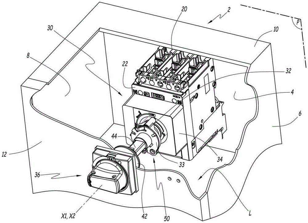
-图1是包括根据本发明的可控电气设备和旋转控制系统的电气外壳的剖视透视示意图;- Figure 1 is a schematic cutaway perspective view of an electrical enclosure comprising a controllable electrical device and a rotary control system according to the invention;
-图2和图3是用于图1的电气外壳的根据本发明的旋转控制系统的一部分的根据特写视图的示意图;- Figures 2 and 3 are schematic diagrams according to a close-up view of a part of a rotation control system according to the invention for the electrical enclosure of Figure 1;
-图4是在根据本发明的旋转控制系统的一部分在图2的剖切平面IV中的示意性横截面;- Fig. 4 is a schematic cross-section in section plane IV of Fig. 2 of a part of a rotation control system according to the invention;
-图5是根据本发明的旋转控制系统的锁定板的根据后视图的示意图;- Figure 5 is a schematic view according to a rear view of the locking plate of the rotary control system according to the invention;
-图6是用于图1的旋转控制系统中的附加手柄的根据剖视图的示意图。- Figure 6 is a schematic view according to a cross-sectional view of an additional handle used in the rotation control system of Figure 1 .
具体实施方式Detailed ways
图1表示电气外壳2。外壳2包括基本上在几何平面P中延伸的后壁4。外壳2还包括顶部和底部侧壁6、8和10。壁6、8和10与几何平面P成直角地延伸。壁4、6、8和10限定壳体L。FIG. 1 shows an electrical enclosure 2 . The housing 2 comprises a rear wall 4 extending substantially in the geometric plane P. The housing 2 also includes top and bottom side walls 6 , 8 and 10 . The walls 6, 8 and 10 extend at right angles to the geometric plane P. The walls 4, 6, 8 and 10 define the housing L.
外壳2还包括门12,该门12可以在打开位置和关闭位置之间可逆地移动,在打开位置中,外壳L向外壳2的外部打开,在关闭位置中,门12关闭外壳L。例如,门12安装成沿着平行于平面P延伸的轴线枢转,使得在其关闭位置,门12面向后壁4。例如,门12安装成通过铰链固定到侧壁6或8中的一个或另一个的外边缘。这里,外壳12具有带有平行六面体基底的梯形形状。壁4、6、8和10以及门12例如由金属制成。The housing 2 also includes a door 12 reversibly movable between an open position in which the housing L opens to the outside of the housing 2 and a closed position in which the door 12 closes the housing L. For example, the door 12 is mounted to pivot along an axis extending parallel to the plane P such that in its closed position the door 12 faces the rear wall 4 . For example, the door 12 is mounted to be secured to the outer edge of one or the other of the side walls 6 or 8 by means of hinges. Here, the housing 12 has a trapezoidal shape with a parallelepiped base. The walls 4, 6, 8 and 10 and the door 12 are for example made of metal.
在本说明书中,除非另有规定,元件的“后面”对应于该元件的朝向后壁4的面,并且其基本上延伸到平面P。元件的“前面”是该后面并且当该门关闭时朝向门12转动。In this specification, unless otherwise specified, the "rear" of an element corresponds to the face of the element facing the rear wall 4 and which extends substantially to the plane P. The "front" of the element is the rear and turns towards the door 12 when the door is closed.
电气外壳2还包括电气设备20,电气设备20在壳体L内部固定地布置在后壁4上的。例如,电气设备20电耦合到要保护的电路的电导体,并且进入外壳2。为了简化图1,未示出这些电导体。The electrical housing 2 also includes
电气设备20可以在两个不同的电气状态之间选择性地和可逆地切换,例如“开”状态和“关”状态。这里,电气设备20是断路器。The
设备20可以借助于开关而在其电气状态之间切换,开关结合在设备20中并且布置在设备20的前面22上。开关在这里是围绕固定轴线X1转动的旋转开关以在其电气状态之间切换电气设备20。轴线X1垂直于几何平面P延伸。The
电气外壳2还包括设备20的旋转控制系统30,以在门12关闭时从外壳2的外部控制电气设备20在其电气状态之间的切换。控制系统30在这里固定到设备20的前面22并且与电气设备20的开关机械耦合。为此,控制系统30包括旋转控制构件32、锁定板33和固定框架34。The electrical enclosure 2 also includes a
在此,框架34固定地并且没有自由度地安装在装置20的前面22上。Here, the
旋转构件32相对于框架34围绕轴线X1在稳定和不同的第一和第二位置之间旋转移动。这里,旋转构件32围绕该轴线X1可旋转地安装在框架34上。旋转构件32在下文中更详细地描述。The rotating member 32 moves rotationally relative to the
在该示例中,旋转构件32在此与该旋转开关围绕轴线X1机械耦合旋转。根据变型,开关是杠杆或摇臂,其可以通过沿着平行于平面P延伸的线施加力而平移移动。在这种情况下,框架34有利地包围运动传递系统,该运动传递系统将旋转构件32绕轴线X1的旋转转换为沿着垂直线的平移力以切换开关。In this example, the rotary member 32 is here mechanically coupled to rotate about the axis X1 with the rotary switch. According to a variant, the switch is a lever or rocker arm which can be moved in translation by applying a force along a line extending parallel to the plane P. In this case, the
控制系统30还包括旋转控制手柄36,其旨在围绕轴线X1固定成与旋转构件32一起旋转。手柄36安装在门12上,这里面向构件32。The
手柄36包括可移动部件38和固定地安装在门12上的固定基座40,可移动部件38可以围绕轴线X2在两个不同位置之间旋转移位,该轴线X2与门12成直角延伸。手柄36链接到联接件42,联接件42围绕轴线X2固定成与可移动部件38一起旋转。The handle 36 includes a movable part 38 which is rotationally displaceable between two different positions about an axis X2 extending at right angles to the door 12 and a fixed base 40 fixedly mounted on the door 12 . The handle 36 is linked to a link 42 which is fixed for rotation with the movable part 38 about the axis X2.
在本说明书中,手柄36的旋转位移是指可移动部件38的旋转位移。In this specification, the rotational displacement of the handle 36 refers to the rotational displacement of the movable member 38 .
当把手36安装在外壳2上时,轴线X2平行于轴线X1。在该示例中,轴线X1和X2然后重合。在一个变型中,轴线X1和X2不重合,而是相对于彼此偏移,例如因为手柄36不面向构件32。在这种情况下,使用适当的机构将来自手柄的运动36连接到构件32。When the handle 36 is mounted on the housing 2, the axis X2 is parallel to the axis X1. In this example, the axes X1 and X2 then coincide. In a variant, the axes X1 and X2 do not coincide, but are offset relative to each other, for example because the handle 36 does not face the member 32 . In this case, the movement 36 from the handle is connected to the member 32 using an appropriate mechanism.
控制系统30还包括具有多边形截面的轴44,其牢固地安装成与旋转构件32一起旋转。轴44基本上沿着轴线X1延伸。当门12关闭时,轴44使得可以固定手柄36与旋转构件32一起旋转。为此,轴44在其端部之一上支撑联接器42。联接件42固定地安装在轴44上,并且可以选择性地与手柄36的可移动部件38断开。The
更具体地,当门12关闭时,联接件42围绕轴线X1将手柄36的可移动部件38与轴44并因此与构件32旋转地固定。More specifically, the link 42 rotationally secures the movable part 38 of the handle 36 with the
当门12处于其打开位置时,轴线X2不再与轴线X1对准。手柄36与联接器32一样处于分离位置。手柄36的可移动部件38与联接件42断开。因此,手柄36与旋转构件32机械地脱离。When the door 12 is in its open position, the axis X2 is no longer aligned with the axis X1. The handle 36 is in the disengaged position like the coupler 32 . The movable part 38 of the handle 36 is disconnected from the coupling 42 . Thus, the handle 36 is mechanically disengaged from the rotating member 32 .
在一个变型中,联接件42由手柄36承载,并且保持固定到可移动部件38。当门12打开时,轴44与联接件42分离。In one variant, the link 42 is carried by the handle 36 and remains fixed to the movable part 38 . When the door 12 is opened, the
轴44在这里固定地安装成与旋转构件32一起旋转。例如,旋转构件32包括具有与轴44的截面互补的多边形截面并且形成在该旋转构件32的中心部分上的腔46,并且在其中接收轴44的端部。旋转构件32包括固定部件48,例如锥尖定位螺钉,以将轴44固定地保持在腔46中,并且因此防止沿着轴线X1的趋向于使轴44与腔46分离的任何平移位移。The
因此,当门12打开时,轴44保持固定到旋转构件32。Thus, when the door 12 is open, the
以这种方式,当门12关闭时,手柄36的旋转旋转地驱动构件32。这里,构件32在两个位置之间的切换通过将手柄36围绕旋转轴线X1转动90°而完成。In this manner, rotation of the handle 36 rotationally drives the member 32 when the door 12 is closed. Here, switching of the member 32 between the two positions is accomplished by turning the handle 36 through 90° about the axis of rotation X1.
控制系统30还包括在图2和图3中示出的阻挡装置50。在该示例中,目的是能够将旋转构件32锁定在其第一位置,也就是说,对应于设备20的关闭状态。为此,当旋转构件32处于其第一位置时,装置50可选择性地在阻挡构型与释放构型之间移位。The
在阻挡构型中,装置50防止旋转构件32移动到其第二位置。在释放构型中,装置50允许旋转构件32移动到其第二位置。In the blocking configuration, the
旋转构件32具有主体52,其几何平面P中的正交几何投影基本上采取盘的形式。旋转构件32包括限定通孔56或孔口的环54。这里,该环平行于平面P延伸。The rotating member 32 has a
有利地,构件32包括形成在主体52的边缘上的标记58,并且其使得可以可视地指示旋转构件32的当前位置。例如,标记58采取箭头的形式。然后,框架34用视觉指示器覆盖,视觉指示器定位成使得当旋转构件32处于其一个或另一个位置时,标记58指向这些指示器中的一个或另一个。Advantageously, the member 32 includes
例如,环54通过刺穿主体52而形成在主体52的周边边缘上。For example, the
阻挡装置50在此包括可移动并且由图4所示的构件32承载的销60。该销60部分地容纳在形成于主体52上的壳体62中。The blocking
销60在相对于构件32的展开位置和缩回位置之间沿着与平面P成直角的轴线X3平移移动并且固定到构件32。The
在展开位置,销60的远端64被接收在形成在框架34上的盲孔66中。例如,销60穿入该孔至少5mm,甚至8mm的长度。因此,销60防止旋转构件32绕轴线X1相对于框架34的旋转。然后,阻挡装置50处于其阻挡构型。In the deployed position, the distal ends 64 of the
在其缩回位置,销60的远端64例如通过缩回到壳体62中而位于孔66的外部。由于销60不存在于孔66中,旋转构件32可以不受阻碍地相对于框架34围绕轴线X1旋转地移动。阻挡装置50被称为处于其释放构型。In its retracted position, the
装置50还包括弹性返回构件68,其在销60上施加返回力到其缩回位置。这里,返回构件68通过一方面固定到壳体62的内壁并且另一方面固定到销60而容纳在壳体62中。例如,返回构件68是螺旋弹簧。The
销60在此包括具有圆形基部并且沿着轴线X3延伸的基本上圆柱形的主体。销60在与远端64相对的端部70上具有由锥形部分74和端子部分76形成的头部72。部分74设置在销60的本体与部分76之间,并且这里采用轴线X3的截头圆锥的形式。部分74的外壁相对于轴线X3呈现例如45°的角度。销60在此由金属制成。端子部分76在此具有圆形形状,例如半球形。壳体62在此具有圆柱形的轴线X3,其内径大于销60的圆柱形主体的直径。The
在该示例中,旋转构件32由金属制成,例如由赋予其足够的硬度和刚度的铜、锌和铝的合金制成。In this example, the rotating member 32 is made of metal, such as an alloy of copper, zinc and aluminum that imparts sufficient hardness and rigidity to it.
锁定板33相对于旋转构件32绕轴线X1可旋转地移动。更具体地,当旋转构件32处于其第一位置时,板33可以通过围绕轴线X1旋转而在锁定位置和解锁位置之间移位。The locking
板33被配置为当阻挡装置50从其解锁位置移位到其锁定位置时将阻挡装置50切换到其阻挡位置。类似地,当板33从其锁定位置移位到其解锁位置时,板33将阻挡装置50从其阻挡构型切换到其释放构型。The
板33在这里是基本上平面的形式,并且当其安装在系统30中时平行于平面P延伸。板33包括中心孔,中心通过轴线X1。因此,板33与旋转构件32同轴地布置。在该示例中,中心孔由旋转构件32的支撑腔46的部分穿过。板33的后面朝向构件32的前面。The
板33还包括限定通孔84的环82,通孔84例如通过在板33的外边缘附近钻孔而形成。该孔84出现在板33的前面和后面上。环82在与环54相同的几何平面中延伸,这里平行于平面P。The
当旋转构件32处于其第一位置并且板33处于其锁定位置时,如图3所示,孔56和84彼此叠置并形成开口86,该开口86能够接收通过插入穿过该开口86而将旋转构件32固定为与锁定板33一起绕轴线X1旋转的锁定工具。例如,这个锁定工具是挂锁。在图3中,锁定工具由线88示意性地表示,其表示通过开口86插入的挂锁的钩环。When the rotating member 32 is in its first position and the
当孔56和84具有至少30%、优选至少50%的共同表面积时,孔56和84被认为是重叠的。优选地、开口86在形成时具有大于或等于0.5cm2的表面积。有利地,开口86具有直径大于或等于0.5cm、优选为1cm、甚至更优选为2cm的盘形。因此,可以通过开口86插入已知的锁定工具,例如电气维护操作者通常使用的夹具或挂锁。Apertures 56 and 84 are considered to overlap when they have at least 30%, preferably at least 50%, common surface area. Preferably,
在解锁位置,孔84和56围绕轴线X1相对于彼此成角度地偏移,并且不形成开口86,如图2所示。例如,小于20%或15%或10%的孔84的表面积与孔56的表面积叠加。在该示例中,孔56和84的表面积完全不重叠。In the unlocked position, the
板33包括支承区域100,支承区域100形成为,当板33从其解锁位置移位到其锁定位置时,通过支承在销60的近端70上而将销60移位到其展开位置。The
在该示例中并且如图4中可以看到的,支承区域100包括倾斜部分102或倾斜平面,以及平直部分104和106。在此,支承区域在板33的周边上面向销60形成。部分102从几何平面P2突出,板33基本上在该平面中延伸,该平面P2形成板33的主平面。板33的倾斜部分102沿着几何平面P3延伸,该几何平面P3与几何平面P2形成角度α。角度α例如在30°和60°之间,优选在40°和50°之间。在该示例中,角度α等于45°。角度α优选地根据销60的锥形部分74的壁的倾斜角度选择。当锁定板33在控制系统30中处于安装构造时,平面P2平行于平面P。In this example and as can be seen in FIG. 4 , the
在该示例中,部分102在平面P2中的正交投影基本上沿着圆弧延伸,这里遵循板33的周边。部分102在此在第一和第二角位置之间延伸,移动远离平面P2从第一角位置到第二角位置。这些角位置在此相对于板33的几何中心限定。在平面P2中测量的这些第一和第二角位置之间的角度取决于销60的行程和角度α。In this example, the orthogonal projection of the
部分102、104和106彼此接触,并且例如由单个部件和板33形成。例如,部分102、104和106通过板33的局部冲压形成。在一个变型中,部件33通过模制形成。部分104基本上平行于平面P2延伸并且将部分102与部分106联接。The
部分106相对于平面P2突出,相对于该平面P2的角度严格大于45°,优选大于或等于55°或75°,甚至作为变型,与平面P2成直角。The
部分102、104和106限定了壳体,当销60处于其缩回位置时,该壳体接收销60的端部70。角度α在部分102的朝向壳体内部的一侧测量。当板33处于其解锁位置时,由于返回构件68施加的回复力E68,销60的部分76接着抵靠部分104。由于端子部分76的半球形形式,销60的近端70和板33的部分104之间的接触表面减小,这在板33相对于旋转构件32移位时限制了板33和销60之间的摩擦力。
当板33通过相对于构件32沿由图4中的箭头F1表示的方向转动板33而从其解锁位置移动到其锁定位置时,部分102将销60从其缩回位置移位到其展开位置。部分102形成凸轮,端子部分76滑动抵靠该凸轮。当板33相对于旋转构件32移位时,部分102沿着轴线X3在销60上施加推力E102。该力E102抵抗并超过由返回构件68施加在销60上的力E68。
当旋转构件32处于其第一位置时,销60面向孔66定位,并且因此相对于壳体62沿着轴线X3滑动,使得端部64逐渐地进入孔66,直到销60定位在其第一展开位置。然后,板33覆盖销的头部72,并且防止销60相对于壳体62的任何随后的位移。When the rotating member 32 is in its first position, the
相反,如果旋转构件32不在其第一位置,则销60不能移位到其展开位置。如果板33相对于旋转构件32旋转以施加如上所述的力E102,则销60移位,但是其远端64与框架34邻接。然后不可能继续移动板33到其锁定位置。因此,只要旋转构件32不在其第一位置,板33就不能移动到其锁定位置,然而由于部分104的长度,板33可以相对于旋转构件32略微移位。Conversely, if the rotating member 32 is not in its first position, the
就其本身而言,部分106防止板33沿相反方向移位,如下文所述。For its part, the
部分102的长度被有利地选择,使得板33在其解锁位置和锁定位置之间的旋转运动足以将销60从其缩回位置完全移位到其展开位置。The length of
因此,当形成开口86时,销60完全处于其缩回位置。锁定工具88插入开口86中,板33被固定为与构件32一起围绕轴线X1旋转,并且销不能从其当前缩回位置移位,从而将旋转构件32固定在其第一位置。Thus, when opening 86 is formed,
有利地,板33包括相对于板33的外表面突出的保护性刀片120。刀片120形成为仅当板33处于其锁定位置时从外部覆盖部件48,如图3所示。例如,叶片120沿着平行于轴线X1的轴线突出。刀片120阻挡对部件48的接近,从而防止轴44的任何拆卸。这种拆卸是不期望的,因为这将使得用户能够分离系统30的组成元件并且因此绕过由构件88提供的锁定。Advantageously, the
当板33处于解锁位置时,刀片120与固定部件48分离,并允许接近该部件,如图2所示。When the
因此,叶片120定位在预定位置,以便仅当该板33处于其锁定位置时覆盖固定部件48。例如,平行于平面P并围绕轴线X1在保护性叶片120和孔口84的几何中心之间测量的角度偏移与以相同方式测量的固定部件48和孔56的几何中心之间的角度偏移相同。Thus, the
有利地,旋转构件32包括形成在其外面之一上并且出现在至少部分地由旋转构件32的内壁界定的容积上的凹槽130,如图5所示。这里,凹槽130是穿过本体52并且在本体52的相对面上在本体52的任一侧上出现的槽。凹槽130包括主要部分132和次级部分134。凹槽130在此平行于几何平面P延伸。Advantageously, the rotating member 32 includes a
主体部分132具有第一开口厚度E1,其在主体52的径向轴线上平行于凹槽130的主要部分的相对边缘之间的平面P测量。次要部分具有第二径向厚度E2,其平行于该次级部分134的相对边缘之间的平面P类似地测量。厚度E2大于厚度E1。The
就其本身而言,板33包括相对于板33的后表面突出的爪136。当板33处于与控制系统30组装的状态时,爪136安装成在凹槽130中滑动。更具体地,爪136插入凹槽130中,使得爪136的保持部分138支承在主体52的后表面上。部分138具有大于主要部分132的开口厚度E1的宽度E3。因此,部分138防止板33相对于旋转构件32在轴线X1上的任何平移位移。当板33在锁定位置和解锁位置之间移位时,爪136仅沿着凹槽130的主要部分132移位。For its part, the
在该示例中,板33包括三个爪136,并且构件32包括三个凹槽,每个凹槽130接收相应的爪136。凹槽136和凹槽130优选地围绕轴线X1均匀分布,例如在120°处。In this example,
次级部分134限定板32的与锁定和解锁位置不同的安装位置。在该安装位置中,板33可以相对于旋转构件32在轴线X1上平移移位,以将每个爪136插入相应的槽130中。The
有利地,一旦爪136插入槽130中,区域100的部分106防止板33返回其安装位置。因为该部分106相对于如前所述的平面P2突出,因此平行于轴线X3,通过以对倾斜部分102所做的方式转动板33,不能使销60从其缩回位置平移移位到其展开位置。Advantageously, the
现在将参照图1至图5描述控制系统30的使用的示例。An example of the use of the
最初,板33处于从系统30拆卸的状态。销60和返回构件68预先安装在装置30中。板33首先安装在旋转构件32上,例如通过螺纹连接通过板33的中心孔80支撑旋转构件32的空腔46。板33被转动,使得爪136布置成面向槽130的次级部分134。然后板33处于其安装位置。然后,板33沿着轴线X1被推向构件32。通过这样做,爪136进入凹槽130。同时,销60的近端70被板33推回,这驱动销60移动到其缩回位置。Initially, the
然后,板33相对于旋转构件32旋转,以使板33进入其解锁位置,如图4所示。例如,板33在该旋转期间沿箭头F1所示的方向转动,爪136离开次级部分134以插入凹槽130的主要部分132中。同时,板33相对于销60移动,直到由板33的部分102、104和106限定的壳体使其面对销60的近端70。然后,板33不再与端部70接触,并且不再反抗由构件68施加的力E68。销60被推到其缩回位置,直到其抵靠板33的平直部分104。由于平直部分106,不再能够在板33上施加沿相反方向的旋转运动以返回到安装位置。因此,避免了当板33在锁定位置时板33不能沿着轴线X1与旋转构件32分离的情况,这种情况会使得由阻挡装置50施加在旋转构件32上的阻挡不起作用。如果发生这种情况,那么可能无意地或者意外地操纵旋转构件32,以未经授权的方式将电气设备20切换到其打开状态。Then, the
一旦板33处于其解锁位置,阻挡装置处于其释放构型。因此,旋转构件32可以在其第一位置和第二位置之间自由地移动,以将电气设备在其打开和关闭状态之间切换。例如,门12被关闭,并且装置20通过手柄36从外壳2的外部被控制。Once the
然后,为了将旋转部件32锁定在其第一位置,门12打开。板33绕轴心X1相对于旋转构件32例如手动地转动,直到孔84和56重叠并形成开口86。同时,支承区域100移位直到倾斜部分102到达与销60的头部72接触,从而施加如前所述的力E102。板33的渐进旋转将销60移动到孔66中的其展开位置。在旋转结束时,板33处于其锁定位置,如图3所示。销60处于其展开位置并防止旋转构件32相对于框架34的任何旋转位移。Then, in order to lock the rotary member 32 in its first position, the door 12 is opened. The
因此,这防止电气设备20切换到其电接通状态。在该锁定位置,孔56和84彼此叠置并一起形成开口86。因此,使用者可以容易地将锁定构件88插入开口86中。只要存在该构件88,板33就保持在其锁定位置,使得相对于构件32的任何位移变得不可能。Thus, this prevents the
当使用者移除锁定构件88时,板33可以再次相对于旋转构件32移位。然后,板33沿相反的旋转方向转动,并且区域100沿与其相反的位移方向如箭头F1所示。在力E68下,销60移动到其缩回位置,直到其抵靠部分104抵靠。同时,孔84和56彼此远离移动,使得插入锁定工具以固定板33和旋转构件32一起变得不可能。板33然后处于其解锁位置,如图2所示。旋转构件32可以自由地移位到其第二位置,以将电气设备20切换到其打开状态。When the user removes the locking
有利地,控制系统30包括仅在图6中示出的附加控制手柄200。手柄200安装在外壳2内的轴44上。该手柄200与手柄36不同。手柄200构造成促进使用者围绕轴线X1的轴44的旋转位移。它还使得可以防止这种旋转变得无意。Advantageously, the
手柄200包括外主体202,外主体202设置有允许轴44通过的中心孔204。手柄200还包括可移动部件206,其可以沿着固定到外主体的轴线Y1相对于主体202平移移动并且与轴线X1成直角。可移动部件206包括外部部分208和限定壳体212的钳口210。The handle 200 includes an outer body 202 provided with a central hole 204 that allows the
可移动部件202可以沿着轴线Y1在第一位置和第二位置之间移动,在第一位置中,轴44与爪210分离并且在壳体212的外部,在第二位置中,轴44由爪210夹持在壳体212内。The movable member 202 is movable along the axis Y1 between a first position, in which the
手柄200还包括返回构件214,例如弹簧,其被配置为沿着轴线Y1在可移动部件206上施加返回力,以使可移动部件206返回到其第一位置。The handle 200 also includes a return member 214, such as a spring, configured to exert a return force on the movable member 206 along the axis Y1 to return the movable member 206 to its first position.
当可移动部分206处于其第一位置时,手柄200相对于轴44围绕轴线X1可旋转地移动。因此,移动手柄200不会导致轴44的任何相应的旋转。When the movable portion 206 is in its first position, the handle 200 is rotatably moved relative to the
有利地,手柄200仍然在轴44上施加非零的力,以避免手柄200在轴44上自由滑动,这使得可以将其保持在使用者期望的位置。Advantageously, the handle 200 still exerts a non-zero force on the
当可移动部分206处于第二位置时,由于夹210在轴44上的作用,手柄200与轴44一起绕轴线X1旋转固定。因此,手柄200的旋转运动带来关于轴44围绕轴线X1的相应旋转运动。When the movable part 206 is in the second position, the handle 200 is fixed in rotation with the
可移动部件206的第一位置和第二位置之间的切换通过沿着轴线Y1在外部部件208上施加压力来产生。当该压力足够高时,其抵抗返回构件214的返回力,并且将可动部分移位到其第二位置。当没有压力施加在外部部件208上时,可移动部件206在返回构件214的作用下恢复其第一位置。Switching between the first and second positions of the movable member 206 is produced by exerting pressure on the outer member 208 along the axis Y1. When this pressure is high enough, it resists the return force of the return member 214 and displaces the movable part to its second position. When no pressure is exerted on the outer part 208, the movable part 206 returns to its first position under the action of the return member 214.
因此,只有当力施加在外部部件208上时,才可以使用手柄200。这样,可以保证手柄200的旋转是用户部分的有意动作的结果,而不是施加在手柄200上的无意的运动。Therefore, the handle 200 can only be used when a force is exerted on the outer member 208 . In this way, it can be ensured that the rotation of the handle 200 is the result of an intentional action on the part of the user, rather than an unintentional movement imposed on the handle 200 .
手柄200可以独立于先前描述的控制系统30来实现。The handle 200 may be implemented independently of the
在一个变型中,设备20不是电气设备。它可以是可控阀。In a variant, the
本发明的不同变型和不同实施例可以彼此组合以形成本发明的新颖实施例。Different variations and different embodiments of the invention can be combined with each other to form novel embodiments of the invention.
Claims (9)
Applications Claiming Priority (2)
| Application Number | Priority Date | Filing Date | Title |
|---|---|---|---|
| FR1651363 | 2016-02-19 | ||
| FR1651363A FR3048119B1 (en) | 2016-02-19 | 2016-02-19 | ROTARY CONTROL SYSTEM FOR AN APPARATUS |
Publications (2)
| Publication Number | Publication Date |
|---|---|
| CN107104011A CN107104011A (en) | 2017-08-29 |
| CN107104011B true CN107104011B (en) | 2020-01-10 |
Family
ID=55808673
Family Applications (1)
| Application Number | Title | Priority Date | Filing Date |
|---|---|---|---|
| CN201710068858.5A Active CN107104011B (en) | 2016-02-19 | 2017-02-08 | Rotation control system for equipment |
Country Status (6)
| Country | Link |
|---|---|
| US (1) | US10345849B2 (en) |
| EP (1) | EP3208820B1 (en) |
| CN (1) | CN107104011B (en) |
| DK (1) | DK3208820T3 (en) |
| ES (1) | ES2711571T3 (en) |
| FR (1) | FR3048119B1 (en) |
Families Citing this family (7)
| Publication number | Priority date | Publication date | Assignee | Title |
|---|---|---|---|---|
| US11261628B2 (en) * | 2017-02-08 | 2022-03-01 | Kason Industries, Inc. | Cold room latch |
| CN109509651B (en) * | 2017-09-15 | 2022-05-27 | Abb 瑞士股份有限公司 | Switchgear and associated switches |
| CN110085463B (en) * | 2018-01-26 | 2023-08-01 | Abb 瑞士股份有限公司 | Lock assemblies for components of power distribution systems |
| FR3091447B1 (en) * | 2018-12-27 | 2021-01-22 | Nexo | Acoustic enclosure frame comprising a device for connecting to another acoustic enclosure and acoustic enclosure comprising such a frame |
| ES2988908T3 (en) | 2020-04-01 | 2024-11-22 | Gorlan Team Slu | Removable knob for operating switchgear and a switchgear device incorporating the removable knob |
| CN114070664A (en) * | 2021-10-25 | 2022-02-18 | 中国航空无线电电子研究所 | Multichannel bus switching device |
| CN114121518A (en) * | 2021-11-23 | 2022-03-01 | 扬戈科技股份有限公司 | Resilience reset mechanism of master controller |
Citations (3)
| Publication number | Priority date | Publication date | Assignee | Title |
|---|---|---|---|---|
| CN1212074A (en) * | 1996-02-21 | 1999-03-24 | 金钟-默勒有限公司 | Protective switch with locking device to prevent switching-on |
| DE19939717A1 (en) * | 1999-08-21 | 2001-02-22 | Moeller Gmbh | Manual operating device electrical switching device, has rotary handle connected to drive plate within ridge with edge segments forming circle when in off position |
| EP1583120A1 (en) * | 2004-03-30 | 2005-10-05 | Rockwell Automation Technologies, Inc. | Rotary service switch for the interior of electrical enclosures having a disconnect switch |
Family Cites Families (3)
| Publication number | Priority date | Publication date | Assignee | Title |
|---|---|---|---|---|
| US20070011922A1 (en) * | 2005-02-11 | 2007-01-18 | Chang-Fu Huang | Disposable cup and cup cover for advertisement |
| FR2894041B1 (en) * | 2005-11-29 | 2007-12-28 | Schneider Electric Ind Sas | LOCKABLE ROTARY CONTROL HANDLE |
| US9396894B2 (en) * | 2013-11-04 | 2016-07-19 | Rocal Corporation | Conductivity power connection |
-
2016
- 2016-02-19 FR FR1651363A patent/FR3048119B1/en not_active Expired - Fee Related
-
2017
- 2017-01-06 US US15/400,493 patent/US10345849B2/en active Active
- 2017-02-08 CN CN201710068858.5A patent/CN107104011B/en active Active
- 2017-02-17 EP EP17156599.7A patent/EP3208820B1/en active Active
- 2017-02-17 ES ES17156599T patent/ES2711571T3/en active Active
- 2017-02-17 DK DK17156599.7T patent/DK3208820T3/en active
Patent Citations (3)
| Publication number | Priority date | Publication date | Assignee | Title |
|---|---|---|---|---|
| CN1212074A (en) * | 1996-02-21 | 1999-03-24 | 金钟-默勒有限公司 | Protective switch with locking device to prevent switching-on |
| DE19939717A1 (en) * | 1999-08-21 | 2001-02-22 | Moeller Gmbh | Manual operating device electrical switching device, has rotary handle connected to drive plate within ridge with edge segments forming circle when in off position |
| EP1583120A1 (en) * | 2004-03-30 | 2005-10-05 | Rockwell Automation Technologies, Inc. | Rotary service switch for the interior of electrical enclosures having a disconnect switch |
Also Published As
| Publication number | Publication date |
|---|---|
| US20170242453A1 (en) | 2017-08-24 |
| US10345849B2 (en) | 2019-07-09 |
| FR3048119B1 (en) | 2018-03-30 |
| FR3048119A1 (en) | 2017-08-25 |
| CN107104011A (en) | 2017-08-29 |
| DK3208820T3 (en) | 2019-01-14 |
| ES2711571T3 (en) | 2019-05-06 |
| EP3208820A1 (en) | 2017-08-23 |
| EP3208820B1 (en) | 2018-11-21 |
Similar Documents
| Publication | Publication Date | Title |
|---|---|---|
| CN107104011B (en) | Rotation control system for equipment | |
| EP2595167B1 (en) | Handle assembly with lock position defeater and related methods | |
| US8115127B2 (en) | Extended drive plate deliberate action rotary handle | |
| US6797903B1 (en) | Extended rotary handle operator | |
| US4851621A (en) | Operating handle for an enclosed electric switch | |
| JP3730662B2 (en) | Safety switch assembly | |
| JP3485892B2 (en) | Switchboard cabinet lock device | |
| JP3176635B2 (en) | Lockable operating device for rotary switch | |
| JP5085109B2 (en) | Lockable rotary operation handle | |
| JP2002175791A (en) | Interlock device for secondary battery | |
| US20210110982A1 (en) | Circuit breaker lockout apparatus | |
| US6935871B2 (en) | Electrical cord plug lock | |
| BR112013019096B1 (en) | PADLOCK | |
| CN110010388B (en) | Rotary disconnector with lockable actuation knob | |
| US7560654B2 (en) | Extended drive plate rotary handle | |
| EP2963208A1 (en) | Lock for portable generators | |
| US10290454B2 (en) | Electronic switching device including a lockable rotary handle having a position off feature | |
| US5959270A (en) | Safety switch | |
| CN210264220U (en) | Blade lock core, lockset, key and lockset system | |
| EP2011937B1 (en) | A lock mechanism | |
| US9053876B2 (en) | Lockable manually-operated actuator for electrical switching devices | |
| EP4517150A1 (en) | Handle safety assembly for industrial machines or plants | |
| JP5992714B2 (en) | Unauthorized operation prevention cam device | |
| CN211776623U (en) | Lock for cabinet | |
| EP2472540B1 (en) | Switching assembly having an interlock device for a selector switch |
Legal Events
| Date | Code | Title | Description |
|---|---|---|---|
| PB01 | Publication | ||
| PB01 | Publication | ||
| SE01 | Entry into force of request for substantive examination | ||
| SE01 | Entry into force of request for substantive examination | ||
| GR01 | Patent grant | ||
| GR01 | Patent grant |